

Page 1

ADAM-5000 Series
RS-485 Based Data Acquisition
and Control System
User's Manual
Page 2

Copyright Notice
This document is copyrighted, 2000, by Advantech Co., Ltd. All
rights are reserved. Advantech Co., Ltd., reserves the right to make
improvements to the products described in this manual at any time
without notice.
No part of this manual may be reproduced, copied, translated or
transmitted in any form or by any means without the prior written
permission of Advantech Co., Ltd. Information provided in this
manual is intended to be accurate and reliable. However, Advantech Co., Ltd. assumes no responsibility for its use, nor for any
infringements upon the rights of third parties which may result from
its use.
Acknowledgments
ADAM is a trademark of Advantech Co., Ltd.
IBM and PC are trademarks of International Business Machines
Corporation.
CE Notification
The ADAM-5000/485 series developed by Advantech Co., Ltd. has
passed the CE test for environmental specifications. Test conditions for passing included the equipment being operated within an
industrial enclosure, using shielded twisted-pair RS-485 cables and
having SFC-6 sleeve core clamps added to the power cable and the
RS-485 cable. In order to protect the ADAM-5000/485 system from
being damaged by ESD (Electrostatic Discharge) and EMI leakage,
we strongly recommend the use of CE-compliant industrial enclosure products, shielded twisted-pair RS-485 cables, and core
clamps.
FM Notification
Advantech’s ADAM-5000 series has passed the FM certification.
According to National Fire Protection Association, work sites are
classified into different classes, divisions and groups based on
hazard considerations. ADAM-5000 series is compliant with the
specifications of Class I, Division 2, Groups A, B, C, and D indoor
hazardous. The FM approval report Job ID is 3000008.
Part No.2000500031 4th Edition
Printed in T aiwan. April 2000
Page 3

A Message to the Customer...
Advantech Customer Services
Each and every Advantech product is built to the most exacting
specifications to ensure reliable performance in the unusual and
demanding conditions typical of industrial environments. Whether
your new Advantech equipment is destined for the laboratory or
the factory floor, you can be assured that your product will provide
the reliability and ease of operation for which the name Advantech
has come to be known.
Your satisfaction is our number one concern. Here is a guide to
Advantech’s customer services. To ensure you get the full benefit
of our services, please follow the instructions below carefully .
Technical Support
W e want you to get the maximum performance from your products.
So if you run into technical difficulties, we are here to help. For
most frequently asked questions you can easily find answers in
your product documentation. These answers are normally a lot
more detailed than the ones we can give over the phone.
So please consult this manual first. If you still can’t find the answer,
gather all the information or questions that apply to your problem
and, with the product close at hand, call your dealer. Our dealers
are well trained and ready to give you the support you need to get
the most from your Advantech products. In fact, most problems
reported are minor and are able to be easily solved over the phone.
In addition, free technical support is available from Advantech
engineers every business day. We are always ready to give advice
on application requirements or specific information on the installation and operation of any of our products.
Page 4

Product Warranty
Advantech warrants to you, the original purchaser, that each of its
products will be free from defects in materials and workmanship for
one year from the date of purchase.
This warranty does not apply to any products which have been
repaired or altered by other than repair personnel authorized by
Advantech, or which have been subject to misuse, abuse, accident
or improper installation. Advantech assumes no liability as a
consequence of such events under the terms of this Warranty.
Because of Advantech’s high quality-control standards and
rigorous testing, most of our customers never need to use our
repair service. If an Advantech product ever does prove defective,
it will be repaired or replaced at no charge during the warranty
period. For out-of-warranty repairs, you will be billed according to
the cost of replacement materials, service time and freight. Please
consult your dealer for more details.
If you think you have a defective product, follow these steps:
1 . Collect all the information about the problem encountered (e.g.
type of PC, CPU speed, Advantech products used, other
hardware and software used etc.). Note anything abnormal and
list any on-screen messages you get when the problem occurs.
2 . Call your dealer and describe the problem. Please have your
manual, product, and any helpful information readily available.
3. If your product is diagnosed as defective, you have to request
an RAM number. When requesting an RMA (Return Material
Authorization) number, please access ADVANTECH's RMA
website: http://www .advantech.com.tw/rma. If the web sever is
shut down, please contact our office directly . You should fill in
the "Problem Repair Form", describing in detail the application
environment, configuration, and problems encountered. Note
that error descriptions such as "does not work" and "failure"
are so general that we are then required to apply our internal
standard repair process.
Page 5

4 . Carefully pack the defective product, a completely filled-out
Repair and Replacement Order Card and a photocopy of dated
proof of purchase (such as your sales receipt) in a shippable
container. A product returned without dated proof of purchase
is not eligible for warranty service.
5. Write the RMA number visibly on the outside of the package
and ship it prepaid to your dealer.
Page 6

Contents
Chapter 1 Introduction ............................................................ 1-1
1.1 Overview.................................................................. 1-2
1.2 System Configuration ............................................... 1-3
1.3 A Few Steps to a Successful System ...................... 1-4
Chapter 2 Installation Guideline ........................................... 2-1
2.1 General ..................................................................... 2-2
2.2 Module Installation ................................................... 2- 6
2.3 I/O Slots and I/O Channel Numbering ..................... 2-6
2.4 Mounting................................................................... 2- 7
2.5 Wiring and Connections............................................ 2-9
Chapter 3 ADAM-5000 System ................................................ 3-1
3.1 Overview.................................................................. 3-2
3.2 Major Features of the ADAM-5000
System...................................................................... 3-2
3.3 System Setup............................................................ 3-6
3.4 T echnical Specifications of the
ADAM-5000 ............................................................ 3-7
Chapter 4 I/O Modules ............................................................ 4-1
4.1 RTD Input Module ................................................... 4- 2
4.2 ADAM-5013 RTD Input Resistance
Calibration ................................................................ 4-5
4.3 Analog Input Modules .............................................. 4-7
4.4 Analog Output Modules ......................................... 4-15
Page 7

4.5 Analog I/O Modules Calibration............................. 4-18
4.6 Digital Input/Output Modules ................................. 4-24
4.7 Relay Output Modules............................................ 4-38
4.8 Counter/Frequency Module.................................... 4-41
Chapter 5 Software Utilities ...................................................5-1
5.1 ADAM Utility Software........................................... 5-2
5.2 DLL (Dynamic Link Library) Driver ....................... 5-8
5.3 DDE (Dynamic Data Exchange) Server ................. 5-9
5.4 ADAM-4000 and ADAM-5000
Windows Utility ...................................................... 5-10
5.4.1 Overview ........................................................................ 5-10
5.4.2 Save Function ................................................................. 5-11
5.4.3 COM Port Settings ........................................................ 5-12
5.4.4 Search Connected modules ............................................. 5-13
5.4.5 Terminal Emulation ........................................................ 5-14
5.4.6 Data Scope ..................................................................... 5-16
5.4.7 Saving a Module’ s Configuration to File ........................ 5-17
5.4.8 Load Module’s Configuration File ................................. 5-19
5.4.9 Module Configuration .................................................... 5-21
5.4.10 Module Calibration ........................................................ 5-23
5.4.11 Data Input and Output .................................................. 5-25
5.4.12 Alarm Settings ................................................................ 5-27
5.4.13 Download Procedure ...................................................... 5-28
Chapter 6 Command Set ........................................................ 6-1
6.1 Introduction .............................................................. 6-2
6.2 Syntax....................................................................... 6-2
6.3 CPU Command Set.................................................. 6-4
6.4 ADAM-5013 RTD Input Command Set................ 6-19
6.5 Analog Input Command Set ................................... 6-37
6.6 ADAM-5017H Analog Input Command Set ......... 6-57
6.7 Analog Input Alarm Command Set ........................ 6-71
Page 8

6.8 Analog Output Command Set ................................ 6-90
6.9 Digital Input/Output Command Set ...................... 6-107
6.10 ADAM-5080 Counter/Frequency
Command Set ........................................................6-115
Chapter 7 Troubleshooting .....................................................7-1
7.1 Hardware Diagnosis ................................................. 7-2
7.2 Software Diagnosis .................................................. 7-2
7.3 System Indicators ..................................................... 7-3
7.4 Communication Problems......................................... 7-5
7.5 I/O Module Troubleshooting..................................... 7-6
Chapter A Quick Start Example ............................................ A-1
A.1 System Requirements to Setup an
ADAM-5000 System .............................................. A-2
A.2 Basic Configuration Hook-up .................................. A-5
A.3 Baud Rate and Checksum........................................ A-8
A.4 A Distributed ADAM-5000 Network
System Hook-up .................................................... A-1 1
Chapter B Data Formats and
I/O Ranges ............................................................ B-1
B.1 Analog Input Formats.............................................. B-2
B.2 Analog Input Ranges - ADAM-5017 and 5018 ...... B-4
B.3 Analog Input Ranges of ADAM-5017H................. B-7
B.4 Analog Output Formats ........................................... B-8
B.5 Analog Output Ranges ............................................ B-8
B.6 ADAM-5013 RTD Input Format and Ranges ........ B-9
Chapter C RS-485 Network .................................................... C-1
C.1 Basic Network Layout ............................................ C-3
Page 9

C.2 Line T ermination...................................................... C-6
C.3 RS-485 Data Flow Control...................................... C-9
Chapter D How to Use the
Checksum Feature ............................................... D-1
D.1 Checksum Enable/Disable....................................... D-2
Chapter E ADAM-4000/5000 System
Grounding Installation ......................................... E-1
E. 1 Power Supplies For relevant wiring issues,
please refer to the following scheme :......................E-2
E.2 Grounding Installation ............................................... E-2
E.3 External DI, DO, AI, AO Wiring Reference ...........E-3
E.4 Requirements for RS-485 signal wires .....................E-3
E.5 Grounding reference (Ground bar for the factory
environment should have a standard resistance
below 5 W)...............................................................E-5
E.6 Some Suggestions on W iring Layout ........................E-6
Chapter F Grounding Reference .......................................... F-1
F.1 Grounding .................................................................F-3
F.2 Shielding ...................................................................F-9
F .3 Noise Reduction T echniques.................................. F-14
F.4 Check Point List ..................................................... F-15
Page 10

Figures
Figure 1-1: ADAM-5000 System Configurations ................................. 1-3
Figure 2-1: ADAM-5000 Diagnostic indicators .................................... 2-3
Figure 2-2: ADAM-5000 Network address DIP switch ........................ 2-4
Figure 2-3: Module alignment and installation ................................... 2-6
Figure 2-4: ADAM-5000 Panel mounting ............................................ 2-7
Figure 2-5: ADAM-5000 Rail mounting ............................................... 2-8
Figure 2-6: ADAM-5000E Rail mounting ............................................. 2-9
Figure 2-7: ADAM-5000 Wiring and connections .............................. 2-10
Figure 2-8: Built-in Communication Ports for Diagnostic
Connection ...................................................................... 2-13
Figure 2-9: Flexible Communication Port Function Connection ....... 2-14
Figure 3-1: Function block diagram .................................................... 3-8
Figure 4-1: ADAM-5013 module frontal view ....................................... 4-2
Figure 4-2: RTD inputs ........................................................................ 4-3
Figure 4-3: Applying calibration resistance ........................................ 4-5
Figure 4-4: ADAM-5017 module frontal view ....................................... 4-7
Figure 4-5: Millivolt and volt input ........................................................ 4-8
Figure 4-6: Process current input ....................................................... 4-8
Figure 4-7: ADAM-5017H module frontal view ..................................4-10
Figure 4-8: Millivolt and volt input ...................................................... 4-11
Figure 4-9: Process current input ..................................................... 4-11
Figure 4-10: ADAM-5018 module frontal view ..................................... 4-14
Figure 4-11: Thermocouple input ........................................................ 4-14
Figure 4-12: ADAM-5024 module frontal view ..................................... 4-16
Figure 4-13: Analog output .................................................................. 4-17
Figure 4-14: Applying calibration voltage ............................................ 4-18
Figure 4-15: Zero calibration ...............................................................4-19
Figure 4-16: Span calibration .............................................................. 4-19
Figure 4-17: Cold junction calibration ................................................. 4-20
Figure 4-18: Output module calibration ..............................................4-23
Figure 4-19: Dip switch setting for digital I/O channel ........................ 4-25
Figure 4-20: ADAM-5050 module frontal view ..................................... 4-25
Page 11

Figure 4-21: Dry contact signal input (ADAM-5050) ............................ 4-25
Figure 4-22: Wet contact signal input (ADAM-5050) ........................... 4-26
Figure 4-23: Digital output used with SSR (ADAM-5050/5056) .......... 4-26
Figure 4-24: ADAM-5051 module frontal view ..................................... 4-27
Figure 4-25: TTL input (ADAM-5051) ...................................................4-28
Figure 4-26: Contact closure input (ADAM-5051) ............................... 4-28
Figure 4-27: ADAM-5051D Module ...................................................... 4-29
Figure 4-28: TTL Input (ADAM-5051D) ................................................ 4-30
Figure 4-29: Contact Closure Input (ADAM-5051D) ............................ 4-30
Figure 4-30: ADAM-5052 module frontal view ..................................... 4-31
Figure 4-31: Isolated digital input (ADAM-5052) ................................. 4-31
Figure 4-32: ADAM-5056 module frontal view ..................................... 4-32
Figure 4-33: Digital output used with SSR (ADAM-5050/5056) .......... 4-33
Figure 4-34: ADAM-5056D Module ...................................................... 4-34
Figure 4-35: ADAM-5056D Application Wiring .................................... 4-35
Figure 4-36: ADAM-5060 module frontal view ..................................... 4-38
Figure 4-37: Relay output .................................................................... 4-38
Figure 4-38: ADAM-5068 module frontal view ..................................... 4-39
Figure 4-39: Relay output .................................................................... 4-40
Figure 4-40: ADAM-5080 Module ........................................................ 4-42
Figure 4-41: Isolated Input Level .........................................................4-42
Figure 4-42: TTL Input Level ................................................................ 4-43
Figure 4-43: Counter / Frequency Mode .............................................. 4-43
Figure 4-44: Wiring for Up/Down Counting ......................................... 4-44
Figure 4-45: Wiring for Bi-direction Counting ...................................... 4-45
Figure 4-46: Wiring for Frequency Mode ............................................. 4-45
Figure 4-47: Setting Alarm Limit .......................................................... 4-46
Figure 4-48: Sending Alarm Signal (recommended settings) ........... 4-47
Figure 4-49: Sending Alarm Signal (settings not recommended) ..... 4-47
Figure 4-50: Digital Output Mapping ................................................... 4-49
Figure 4-51: Jumper Location on the ADAM-5080 Module ................. 4-50
Figure 4-52: TTL/Isolated Input Level Selectting ................................ 4-50
Figure 5-1: Main screen ...................................................................... 5-3
Figure 5-2: Setup options .................................................................... 5-4
Figure 5-3: Zero Calibration ................................................................ 5-6
Figure 5-4: Terminal emulation ........................................................... 5-7
Figure 5-5: Display the connected module ....................................... 5-11
Page 12

Figure 5-6: Save the information of connected modules to txt file .... 5-12
Figure 5-7: Setup options .................................................................. 5-12
Figure 5-8: Checksum function enabled ..........................................5-15
Figure 5-9: The connection for the Data Scope function .................. 5-16
Figure 5-10: Monitor the issuing commands from PC#1 ................... 5-17
Figure 6-1: Baud rate codes ................................................................ 6-6
Figure 6-2: Analog module error codes ............................................ 6-18
Figure 6-3: Data format for 8-bit parameters ....................................6-38
Figure 6-4: Data format of 8-bit parameters ..................................... 6-92
Figure A-1: Power supply connections ............................................... A-4
Figure A-2: ADAM-5000 system hook-up and configuration ............... A-6
Figure A-3: Grounding the INIT* terminal .......................................... A-10
Figure A-4: ADAM-5000 network system hook-up ............................ A-11
Figure C-1: Daisychaining .................................................................. C-3
Figure C-2: Star structure .................................................................... C-4
Figure C-3: Random structure ............................................................ C-5
Figure C-4: ADAM-4000 and ADAM-5000 in a network ...................... C-6
Figure C-5: Signal distortion ............................................................... C-7
Figure C-6: Termination resistor locations ......................................... C-8
Figure C-7: RS-485 data flow control with RTS .................................. C-9
Figure E-1: Grounding Scheme ......................................................... E-2
Figure E-2: External Terminal Block and Fan ..................................... E-3
Figure E-3: Grounding for on-site facilities and ADAM-5000/4000
Systems ........................................................................... E-4
Figure E-4: Grounding for signal wires .............................................. E-4
Figure E-5 : Grounding Reference ...................................................... E-5
Figure F-1: Think the EARTH as GROUND......................................... F-3
Figure F-2: Grounding Bar. .................................................................. F-4
Figure F-3: Normal mode and Common mode. ................................. F-5
Figure F-4: Normal mode and Common mode. ................................. F-6
Figure F-5: The purpose of high voltage transmission ...................... F-7
Figure F-6: wire impedance. ............................................................... F-7
Figure F-7: Single point groundinF. (1) ............................................... F-8
Figure F-8: Single point groundinF. (2) ............................................... F-9
Figure F-9: Single isolated cable ........................................................ F-9
Figure F-10: Double isolated cable ..................................................... F-10
Page 13

Figure F-11: System Shielding ............................................................ F-11
Figure F-12: The characteristic of the cable ........................................ F-12
Figure F-13: System Shielding (1) ...................................................... F-13
Figure F-14: System Shielding (2) ...................................................... F-13
Figure F-15: Noise Reduction Techniques ......................................... F-15
Page 14

Tables
Table 4-1: Technical specifications of ADAM-5013 ............................. 4-4
Table 4-2: Calibration resistances of ADAM-5013 .............................. 4-6
Table 4-3: Technical specifications of ADAM-5017 ............................. 4-9
Table 4-4: Technical specifications of ADAM-5017H ........................ 4-12
Table 4-5: ADAM-5017H input signal ranges .................................... 4-13
Table 4-6: Technical specifications of ADAM-5018 ........................... 4-15
Table 4-7: Technical specifications of ADAM-5024 ........................... 4-17
Table 4-8: Calibration voltage of ADAM-5017/5018 .......................... 4-21
Table 4-9: Calibration voltage of ADAM-5017H ................................. 4-22
Table 4-10: Technical specifications of ADAM-5050 ........................... 4-27
Table 4-11: Technical specifications of ADAM-5051 ........................... 4-28
Table 4-12: Comparison between ADAM-5051 and ADAM-5051D .... 4-30
Table 4-13: Technical specifications of ADAM-5052 ........................... 4-32
Table 4-14: Technical specifications of ADAM-5056 ........................... 4-33
Table 4-15: Main Units Supporting Digital Output Holding Funciton .. 4-36
Table 4-16: Comparison between ADAM-5056 and ADAM-5056D .... 4-37
Table 4-17: Technical specifications of ADAM-5060 ........................... 4-39
Table 4-18: Technical specifications of ADAM-5068 ........................... 4-40
Table 4-19: ADAM-5080 technical specifications ................................4-51
Page 15

1
Introduction
Page 16

Introduction
1.1 Overview
The ADAM-5000 series is a complete product line that provides a wide
variety of features in a data acquisition and control application. It
includes 4 I/O-slots ADAM-5000/485 and 8 I/O-slots ADAM-5000E.
They are remotely controlled by the host computer through a set of
commands and transmitted in a RS-485 network. The system kernel is
small, but offers many good features to the users. The modular
design also provides more flexibility in the system configuration. The
following is a summary of the major ADAM-5000 system components.
ADAM-5000 System Kernel
The ADAM-5000/485 system kernel includes a CPU card, a power
regulator, a 4-slot base, a built-in RS-232 communication port and one
built-in RS-485 communication port. The 5000E system includes all of
the above components, except it has an 8-slot base. Details of the
system kernel features and more are covered in Chapter 3.
I/O Configuration
The ADAM-5000/485 CPU can support up to 64 I/O points with the 4slot base currently available.The ADAM-5000E CPU can support up to
128 I/O points with the 8-slot base currently available. These points
can be assigned as input or output points.
I/O Modules
The ADAM-5000 series has a complete range of I/O modules for your
applications. A full range of digital modules which support 10 to
30 VDC and relay outputs are offered. The analog modules provide
16-bit resolution and programmable input and output signal ranges
(including bipolar).
Software Utilities
There are some software utilities available to the ADAM-5000
systems. The DOS and Windows utility software helps you to
configure your ADAM-5000. The DLL (Dynamic Link Library) is
provided to write W indows applications, and the DDE (Dynamic Data
Exchange) server provides links to popular Windows packages such
as Intouch, FIX DMACS, Advantech GeniDAQ, etc.
1-2 ADAM-5000
Page 17
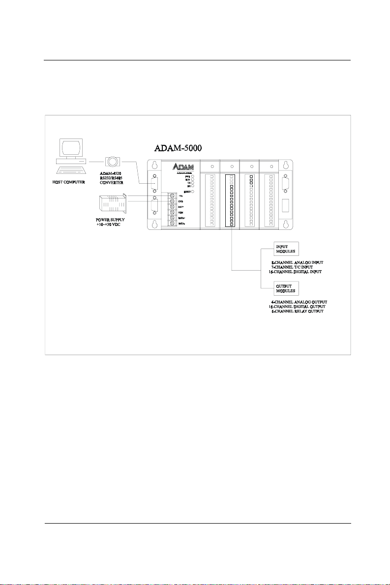
1.2 System Configuration
The following diagram shows the system configurations possible with
the ADAM-5000.
Chapter 1
Figure 1-1 ADAM-5000 System Configurations
Note: To avoid system over heating, only f our ADAM-5024
are allowed to be installed on AD AM-5000E.
ADAM-5000 1-3
Page 18

Introduction
1.3 A Few Steps to a Successful System
Step 1: Review the Installation Guideline
You should always make safety your first priority in any system
application. Chapter 2 provides several guidelines that will help
provide a safer, more reliable system.
Step 2: Understand the System Kernel
The system module is the heart of ADAM-5000 system. Make sure
you take time to understand the various features and setup requirements.
Step 3: Understand the I/O System Configurations
It is important to understand how your I/O modules can be configured.
It is also important to understand how the system power budget is
calculated. This can affect your I/O configuration.
Step 4: Understand the Utility Software
Before you begin to link your applications in your host computer with
the ADAM-5000 systems, it is very helpful to understand how the
DOS and Windows utility software helps you configure your
ADAM-5000.
Step 5: Review the Programming Concepts
All control systems differ in some areas. The ADAM-5000 system
allows you to develop your applications in DOS or Windows. It
provides an ASCII command set, DLL (Dynamic Library Link) and DDE
(Dynamic Data Exchange) server to you.
Step 6: Understand the Troubleshooting Procedures
Many things can be happened on the factory floor: switches fail, the
power supply is incorrect, etc. In most cases, the majority of the
troubleshooting time is spent trying to locate the problems. The
ADAM-5000 system has some built-in features that help you quickly
identify problems.
1-4 ADAM-5000
Page 19

2
Installation Guideline
Page 20

Installation Guideline
2.1 General
Environmental Specifications
The following table lists the environmental specifications that generally apply to the ADAM-5000 system (System kernel and
I/O modules).
Specification Rating
Storage temperature -13 to 185°F (-25 to 85°C)
Ambient operating
temperature
Ambient humidity* 5 to 95%, non-condensing
Atmosphere No corrosive gases
14 to 158°F (-10 to 70°C)
* Equipment will operate below 30% humidity . However , static
electricity problems occur much more frequently at lower humidity
levels. Make sure you take adequate precautions before you touch
the equipment. Consider using ground straps, antistatic floor coverings, etc. if you use the equipment in low humidity environments.
Power Requirements
Although the ADAM-5000 systems are designed for standard
industrial unregulated 24 VDC power supply, they accept any power
unit that supplies within the range of +10 to +30VDC. The power supply
ripple must be limited to 100 mV peak-to-peak, and the immediate ripple
voltage should be maintained between +10 and +30 VDC.
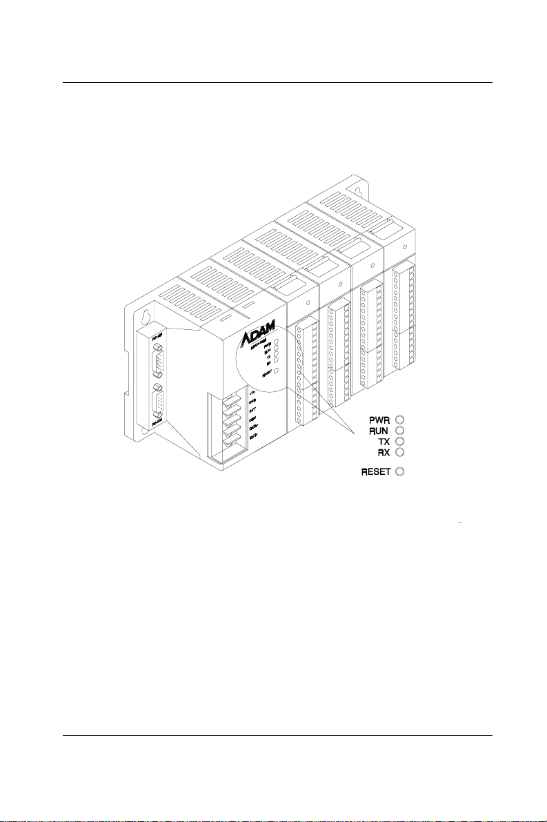
Diagnostic Indicators
Diagnostic indicators are located on the front panel of the ADAM
system. They show both normal operation and system status in your
remote I/O system. The indicators are:
• System status (PWR, RUN)
• Communication status (TX, RX)
• I/O module status
2-2 ADAM-5000
Page 21
Chapter 2
A complete description of the diagnostic indicators and how to use
them for troubleshooting is explained in Chapter 7.
Figure 2-1 ADAM-5000 Diagnostic indicators
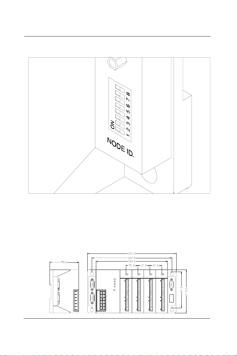
Setting the Network Address Switch
Set the network address using the 8-pin DIP switch. Valid settings
range from 0 to 255 (00h to FFh) where ON in any of the 8 DIP switch
positions equates to a binary 1, and OFF equates to a binary 0.
For example, if the Node ID is 03h the DIP switch settings for switches
1 and 2 (representing bits 1 and 2) would both be ON while the rest of
the switches would be OFF . The default Node ID is 01h
ADAM-5000 2-3
Page 22
Installation Guideline
Figure 2-2 ADAM-5000 Network address DIP switch
Dimensions and Weights (ADAM-5000)
The following diagrams show the dimensions of the system unit and
an I/O unit of the ADAM-5000. All dimensions are in millimeters.
2-4 ADAM-5000
Page 23
Chapter 2
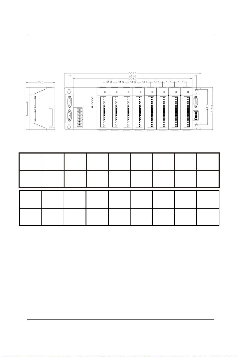
Dimensions and Weights (ADAM-5000E)
The following diagrams show the dimensions of the system unit and
the I/O unit of the ADAM-5000E. All dimensions are in millimeters.
Module
Weight
Module
Weight
5000/485 5000E 5013 5017 5017H 5018 5024 5050
470g
5051 5051D 5052 5056 5056D 5060 5068 5080
65g 45g 68g 68g 45g 85g 65g 52g
ADAM-5000 2-5
45g525g 79g 45g 72g 75g 63g
Page 24
Installation Guideline
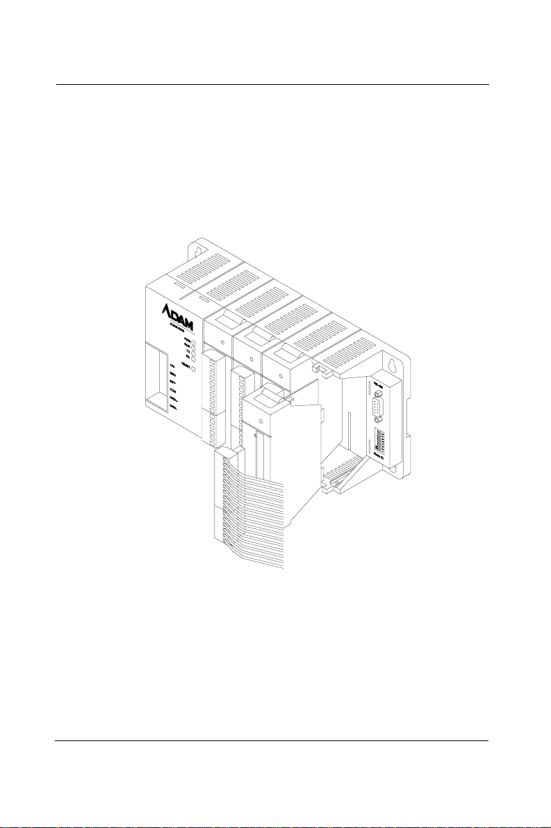
2.2 Module Installation
When inserting modules into the system, align the PC board of the
module with the grooves on the top and bottom of the system. Push
the module straight into the system until it is firmly seated in the
backplane connector. Once the module is inserted into the system,
push in the retaining clips (located at the top and bottom of the
module) to firmly secure the module to the system.
Figure 2-3 Module alignment and installation
2.3 I/O Slots and I/O Channel Numbering
The ADAM-5000/485 system each provides 4 slots for use with I/O
modules. The I/O slots are numbered 0 thru 3, and the channel
numbering of any I/O module in any slot starts from 0. The ADAM5000E system each provides 8 slots for use with I/O modules. The
slots are numbered 0 thru 7. For example, ADAM-5017 is a 8-channel
analog input module, its channel numbering is 0 through 7.
2-6 ADAM-5000
Page 25
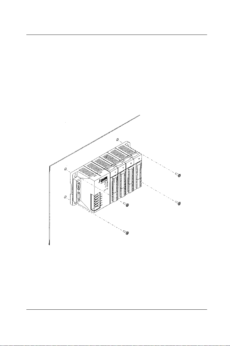
2.4 Mounting
The ADAM-5000 system can be installed on a panel or DIN rail.
Panel Mounting
Mount the system on the panel horizontally to provide proper ventilation. You cannot mount the system vertically, upside down or on a flat
horizontal surface. A standard #7 tating screw (4mm diameter) should
be used.
Chapter 2
Figure 2-4 ADAM-5000 Panel mounting
ADAM-5000 2-7
Page 26
Installation Guideline
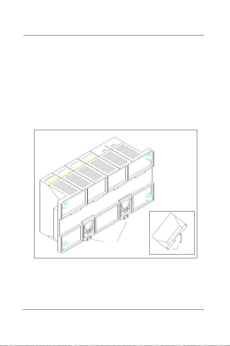
DIN Rail Mounting
The system can also be secured to the cabinet by using mounting
rails. If you mount the system on a rail, you should also consider
using end brackets on each end of the rail. The end brackets help
keep the system from sliding horizontally along the rail. This helps
minimize the possibility of accidentally pulling the wiring loose. If you
examine the bottom of the system, you will notice two small retaining
clips. To secure the system to a DIN rail, place the system onto the rail
and gently push up on the retaining clips. The clips lock the system
on the rail. T o remove the system, pull down on the retaining clips, lift
up on the base slightly, and pull it away from the rail.
Retaining Clips
Figure 2-5 ADAM-5000 Rail mounting
2-8 ADAM-5000
Page 27
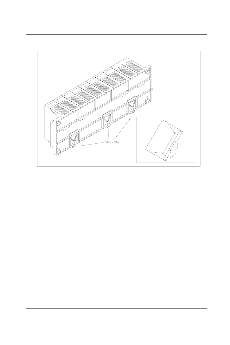
Figure 2-6 ADAM-5000E Rail mounting
2.5 Wiring and Connections
Chapter 2
This section provides basic information on wiring the power supply
and I/O units, and on connecting the network.
DC Power Supply Unit Wiring
Be sure that the DC power supply voltage remains within the allowed
fluctuation range of between 10 to 30 VDC. T erminals +VS and GND are
for power supply wiring.
Note: The wire(s) used should be at least 2mm2.
ADAM-5000 2-9
Page 28
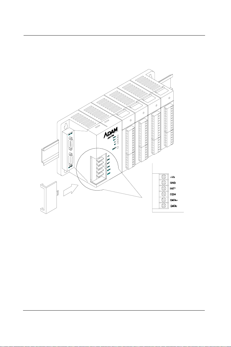
Installation Guideline
INIT* is used for changing baud rate and checksum. COM is provided
as reference to the RS-485 ground signal. DATA+ and DATA- are
provided for the RS-485 twisted pair connection.
Figure 2-7 ADAM-5000 Wiring and connections
I/O Modules Wiring
The system uses plug-in screw terminal blocks for the interface
between I/O module and field devices. The following information must
be considered when connecting electrical devices to I/O modules.
1 . The terminal block accepts 0.5 mm2 to 2.5 mm2 wires
2. Always use a continuous length of wire, do not combine
wires to attain needed length
3. Use the shortest possible wire length
4 . Use the wire trays for routing where possible
2-10 ADAM-5000
Page 29
Chapter 2
5 . Avoid running wires near high energy wiring
6 . A void running input wiring in close proximity to output
wiring where possible
7. Avoid creating sharp bends in the wires
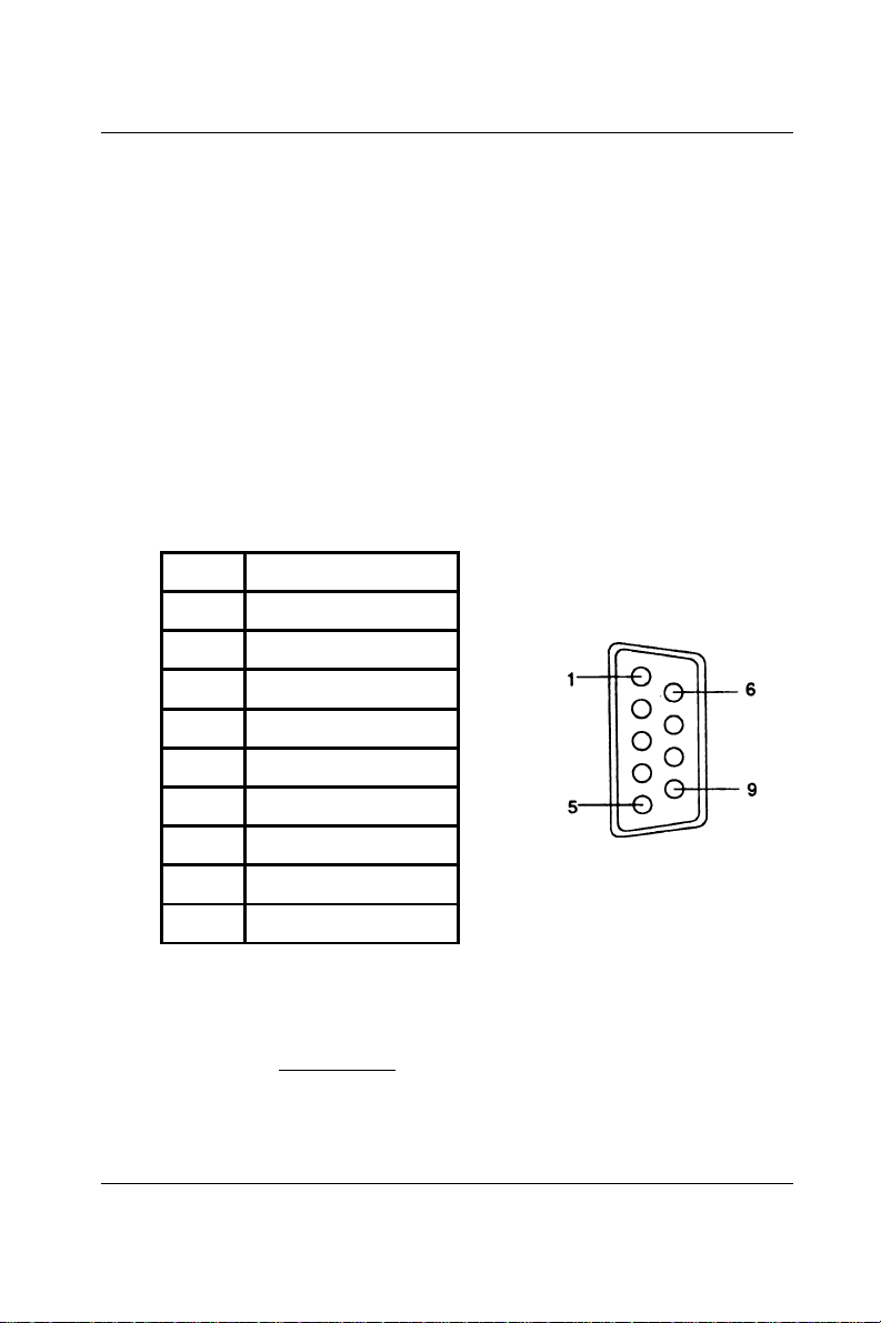
RS-485 Port Connection
There is a pair of DB9 ports in the ADAM-5000 system. The ports are
designed to link the RS-485 through a cable to a network in a system.
The pin assignment of the port is as follows:
Pin No. Description
Pin 1 RS-485 Data -
Pin 2 RS-485 Data +
Pin 3 Not Used
Pin 4 Not Used
Pin 5 RS-485 Signal Ground
Pin 6 Not Used
Pin 7 Not Used
Pin 8 Not Used
Pin 9 Not Used
Note: The wiring of the RS-485 should be through a twisted
pair. To reduce electrical noise, it should be twisted
as tightly as possible
ADAM-5000 2-11
Page 30
Installation Guideline
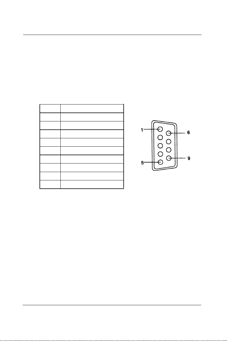
RS-232 Port Connection
The RS-232 port is designed for field configuration and diagnostics.
Users may connect a notebook PC to the RS-232 port to configure or
troubleshoot your system in the field. Further, the ADAM-5000
system can also be configured as the slave of the host computer
through this port connection. The pin assignment of the port is as
follows:
Pin No. Description
Pin 1 Not Used
Pin 2 Data Receive (RxD)
Pin 3 Data Send (TxD)
Pin 4 Not Used
Pin 5 RS-232 Signal Ground (GND)
Pin 6 Not Used
Pin 7 Not Used
Pin 8 Not Used
Pin 9 Not Used
Built-in Communication Ports for Diagnostic
Connection (ADAM-5000E only)
The Built-in Communication Ports for Diagnostic Function enables
users to perform a quick diagnostics to locate where the system is at
fault.
2-12 ADAM-5000
Page 31

Chapter 2
This Diagnostic Function requires the RS-485 port of ADAM-5000E to
be connected to COM1 of host PC, and the RS-232 port of
ADAM-5000E to COM2 of the previous host PC or other PCs. Then
you should install software such as ComWatch or Hyperterminal and
so on to monitor the commands that are being issued and the subsequent responses from connected modules.
Host PC
COM2
ComWatch
Hyper terminal
Software
COM1
Notebook
ADAM
ADAM-4520
RS-485
RS-232
ADAM-5000/E ADAM-5000/E
RS-485
ADAM
ADAM-4000
ADAM
ADAM-5000/485
A
DAM
ADAM-5000
PWR
RUN
COMM
BATT
RESET
+5V
GND
INT*
COM
DATA+
DATA-
Figure 2-8 Built-in Communication Ports for Diagnostic
Connection
Flexible Communication Port Function
Connection(ADAM-5000E only)
The Flexible Communication Port Function prevents ADAM-5000E
from system glitches due to communication line problems.
This function enables simultaneous connections via COM1 and COM2
port of your host PC to the RS-232 and RS-485 port of ADAM-5000E
specifically. While working in conjunction with specific HMI software
(e.g. AFX, FIX) that offers COM Port Backup Function, ADAM-5000E
can circumvent failed communication on one port by switching to
another available port to continue program execution.
ADAM-5000 2-13
Page 32

Installation Guideline
Host PC
COM2
AFX FIX
RS-232
COM1
ADAM
RS-485
ADAM-4520
ADAM-5000E
A
DAM
ADAM-5000 ADAM-5000
PWR PWR
RUN RUN
COMM COMM
BATT BATT
RESET RESET
+5V
GND
INT*
COM
DATA+
DATA-
A
DAM
+5V
GND
INT*
COM
DATA+
DATA-
ADAM-5000E
RS-485
ADAM
ADAM-4000
ADAM
ADAM-5000/485
A
DAM
ADAM-5000
PWR
RUN
COMM
BATT
RESET
+5V
GND
INT*
COM
DATA+
DATA-
Figure 2-9 Flexible Communication Port Function Connection
2-14 ADAM-5000
Page 33

3
ADAM-5000 System
Page 34

ADAM-5000 System
3.1 Overview
The ADAM-5000 series is a data acquisition and control system which
can control, monitor and acquire data through multichannel I/O
modules. Encased in rugged industrial grade plastic bases, the
systems provide intelligent signal conditioning, analog I/O, digital I/O,
RS-232 and RS-485 communication. The ADAM-5000/485 can handle
up to any 4 combinations of I/O modules (64 I/O points), while the
ADAM-5000E can handle up to 8 combinations of I/O modules (128 I/
O points). The systems communicate with their controlling host over a
multi-drop RS-485 network.
3.2 Major Features of the ADAM-5000 System
The ADAM-5000 system consists of two major parts: the system
kernel and I/O modules. The system kernel includes a CPU card, power
regulator, 4-slot base, 8-slot base, built-in RS-232 communication port,
and a pair of built-in RS-485 ports. It also offers the following major
features:
The CPU's Basic Functions
The CPU is the heart of the system and has the following basic
functions:
• Data acquisition and control for all I/O modules in the system
• Linearization of T/C (Thermocouple)
• Communication software and command set
• Calibration software and command set
• Alarm monitoring
• Management of the EEPROM device that holds the system
parameters
• Data transformation
• Diagnosis
3-2 ADAM-5000
Page 35

Chapter 3
Diagnosis
There are 4 LEDs (indicated as PWR, RUN, TX and RX) to provide
visual information on the general operation of the ADAM-5000
system. The LEDs also indicate the error status when the
ADAM-5000 system performs the self test. Besides the LED indicators, the system also offers software diagnosis via the RS-232 port.
For details, refer to Chapter 7.
3-Way Isolation and Watchdog Timer
Electrical noise can enter a system in many different ways. It may enter
through an I/O module, a power supply connection or the communication ground connection. The ADAM-5000 system provides isolation
for I/O modules (3000 VDC), communication connection (2500 VDC) and
communication power connection (3000 VDC). The 3-way isolation
design prevents ground loops and reduces the effect of electrical
noise to the system. It also offers better surge protection to prevent
dangerous voltages or spikes from harming your system. The system
also provides a W atchdog timer to monitor the microprocessor . It will
automatically reset the microprocessor in ADAM-5000 system if the
system fails.
Remote Software Configuration and Calibration
The ADAM-5000 system merely issues a command from the host
computer, you can change an analog input module to accept several
ranges of voltage input, current input, thermocouple input or RTD
input. With the exception of system node address, all the parameters
including speed, parity, HI and LO alarm, and calibration parameters
setting may be set remotely. Remote configuration can be done by
using either the provided menu-based software or the command set's
configuration and calibration commands. By storing configuration and
calibration parameters in a nonvolatile EEPROM, the systems are able
to retain these parameters in case of power failure.
Flexible Alarm Setting
The ADAM-5000 system provides a flexible alarm setting method via
an utility software (ADAM.EXE) between analog input modules and
digital output modules. The user may configure a point of any digital
output module plugged into any slot as the High alarm or Low alarm
ADAM-5000 3-3
Page 36

ADAM-5000 System
output of a channel of an analog input module. The relationship and
their High/Low alarm limits may be downloaded into the system‘s
EEPROM by the host computer.
The alarm functions can be enabled or disabled remotely. When the
alarm function is enabled, the user may select whether the digital
output is triggered. If the digital outputs are enabled, they are used to
indicate the High and Low Alarm state. The High and Low alarm
states can be read at any time by the host computer.
Every A/D conversion will be followed by a comparison with the High
and Low limit. When the input value is over the High limit or below
the Low limit, the High or Low alarm state is set to ON.
There are two alarm mode options: Momentary and Latching.
If the alarm is in Latching mode, the alarm will stay on even when the
input value returns within limits. An alarm in Latching mode can be
turned OFF by issuing a Clear Alarm command from the host computer.
A Latching alarm is cleared by the microprocessor when the opposite
alarm is set
For example, the alarm is in latching mode and the High alarm is turned
ON. When the module receives a value that is lower than the Low
alarm limit, the microprocessor will clear the High alarm and turn the
Low alarm ON.
When the alarm is in Momentary mode, the alarm will be turned ON
when the input value is outside of alarm limits and OFF while the input
value remains within alarm limits. The arrangement of coupling High
and Low alarm states with digital outputs may be utilized to build ON/
OFF controllers that can operate without host computer involvement.
Connectivity and Programming
ADAM-5000 systems can connect to and communicate with all
computers and terminals. They use either RS-232 or RS-485 transmission standards and communicate with ASCII format commands.
However, users can only select and use one communication port at
any time. All communications to and from the system are performed in
ASCII, which means that ADAM-5000 systems can be
3-4 ADAM-5000
Page 37

Chapter 3
programmed in virtually any high-level language. The details of all
commands will be covered in Chapter 6.
Flexible Communication Connection
ADAM-5000s built-in RS-232/485 conversion capability enables users
to freely choose either RS-232 port or RS-485 port to connect with host
PC. When user select either port to connect with their host PC, the
other port could be utilized according to their specific needs.
For example, if RS-232 port is selected for connection with host PC,
the RS-485 port can be used for connection with DA&C modules (such
as ADAM-5000/485, ADAM-5000, ADAM-4000 modules). Thus users
save extra costs for another RS-232/485 conversion device (e.g.
ADAM-4520).
Or if users select RS-485 port for host PC connection, the RS-232 port
can then have different usage such as described in the following
sections (see Built-in Communication Ports for Field Diagnostics and
Flexible Communication Port)
Built-in Communication Ports for Diagnostics
(ADAM-5000E only)
When users utilize application software to control their system,
ADAM-5000E can provide another port to let user monitor at any time
the communication quality and condition as a reference to mainte-
nance and test. When error occurs in the system, users can perform a
quick diagnostics to locate the fault. A considerable amount of
troubleshooting efforts can be saved. For example, using popular
ComWatch software, users can watch the current execution and
response of a certain command. It is very convenient to identify
whether it is communication or the hardware product that is causing
the problem.
Flexible Communication Port (ADAM-5000E only)
ADAM-5000E provides a further application. Users can simultaneous-
ly connect COM1 and COM2 of host PC to RS-232 and RS-485 port of
ADAM-5000E. When host PC issues a command through one of the
COM ports but receives no response (the other port will serve as
backup), the COM Port Backup Function of HMI software (e.g. AFX,
FIX) will automatically switch to another COM port to continue
ADAM-5000 3-5
Page 38

ADAM-5000 System
program execution without undue influence on your system. Probability of a system crash has thus minimized.
3.3 System Setup
A Single System Setup thru the RS-232 Port
If users would like to use a PC to locally control and monitor a simple
application, the ADAM-5000 system provides up to 64 points or 128
points and front-end wiring through the RS-232 port to the host
computer.
A Distributed I/O Setup thru the RS-485 Network
The RS-485 network provides lower-noise sensor readings as the
systems can be placed much closer to the source. Up to 256
ADAM-5000 systems may be connected to an RS-485
multi-drop network by using the ADAM-4510/4510S RS-485 repeaters,
extending the maximum communication distance to 4,000 ft. The host
computer is connected to the RS-485 network from one of its COM
ports through the ADAM-4520/4522 RS-232/RS-485 converter.
T o boost the network's throughput, the ADAM-4510/4510S RS-485
repeaters use a logical RTS signal to manage the repeater's direction.
Only two wires are needed for the RS-485 network: DA TA+ and
DA TA-. Inexpensive, shielded twisted-pair wiring is employed.
3-6 ADAM-5000
Page 39

Chapter 3
3.4 Technical Specifications of the ADAM-5000
Processor
CPU
RAM
ROM (Flash)
I/O Capacity
Watchdog Timer
Power Consumption
80188, 16-bit microprocessor
32 KB
128 KB
4 slots (ADAM-5000/485)
8 slots (ADAM-5000E)
Ye s
1.0 W (ADAM-5000/485)
4.0 W (ADAM-5000E)
Communication
RS-485 Ports 2, 1 each for input and output
Extended RS-232 Ports 1
Wiring RS-485, twisted pair
Speed 1200 bps to 115.2 Kbps
Max. Communication Distance 4000 ft. (1.2 Km)
Network Expansion Up to 256 ADAM-5000 systems
Protection Transient supression on RS-485
Protocol ASCII command/respones
per host serial port over twisted
pair wires
communication lines
Asynchoronous Data Format 1 start bit, 8 data bits, 1 stop bit,
Communication Error Check With checksum
no parity (1 start, 8-N-1)
ADAM-5000 3-7
Page 40

ADAM-5000 System
Isolation
Connection Power 3000 Vdc
Input/Output 3000 Vdc
Co mmunica ti on
2500 Vdc (ADAM-5000/485)
3000 Vdc (ADAM-5000E)
Diagnosis
Status Indicators
Self-Test
Software Diagnosis
- Power
- CPU
- Communication
- I/O modules
Yes, while on
Yes
Basic Function Block Diagram
Opto-Cou pled
GND
Isolation
Power
Isolation
WDT&
Reset
DATA+
COMM.
Controller
DATA-
+V
Rectifier
&
Filter
Memory
16 Bit
up
+5V GND
P. S.
Power
Converter
Bus
+10~
+30Vdc
Figure 3-1 Function block diagram
3-8 ADAM-5000
Page 41

4
I/O Modules
Page 42

I/O Modules
4.1 RTD Input Module
ADAM-5013 3-channel RTD input module
The ADAM-5013 is a 16-bit, 3-channel RTD input module that features
programmable input ranges on all channels. This module is an extremely cost-effective solution for industrial measurement and monitoring
applications. Its opto-isolated inputs provide 3,000 VDC of isolation
between the analog input and the module, protecting the module and
peripherals from damage due to high input line voltage.
Note: Owing to the conversion time required by the A/D
converter, the initialization time of each AD AM-5013
module is 5 seconds. Thus the total initialization
time will be about 20 seconds if all 4 I/O slots in an
ADAM-5510/P31 main unit contain AD AM-5013
modules.
ADAM-5013
3 RTD
ADAM-5013
1
EXC0+
SEN0+
SEN0-
EXC0+
A.GND
EXC1+
SEN1+
SEN1-
EXC1+
A.GND
EXC2+
SEN2+
SEN2-
EXC2-
A.GND
16
Figure 4-1: ADAM-5013 module frontal view
4-2 ADAM-5000
Page 43

Application wiring
EXC0+
SEN0+
SEN0-
EXC0-
A.GND
EXC0+
SEN0+
Chapter 4
2 Wire
RTD
SEN0-
EXC0-
A.GND
EXC0+
SEN0+
SEN0-
EXC0-
A.GND
3 Wire
RTD
4 Wire
RTD
Figure 4-2: RTD inputs
ADAM-5000 4-3
Page 44

I/O Modules
Technical specifications of ADAM-5013
Analog input channels
Input type
RTD type and temperature
range
Isolation voltage
Sampling rate
Input impedance
Bandwidth
three
Pt or Ni RTD
Pt -100 to 100° C a=0.00385
Pt 0 to 100° C a=0.00385
Pt 0 to 200° C a=0.00385
Pt 0 to 600° C a=0.00385
Pt -100 to 100° C a=0.00392
Pt 0 to 100° C a=0.00392
Pt 0 to 200° C a=0.00392
Pt 0 to 600° C a=0.00392
Ni -80 to 100° C
Ni 0 to 100° C
3000 V
DC
10 samples/sec (total)
2 MΩ
13.1 Hz @ 50 Hz,
15.72 Hz @ 60 Hz
Input connections
Accuracy
Zero drift
Span drift
CMR@50/60 Hz
NMR@50/60 Hz
Power consumption
2, 3 or 4 wire
± 0.1% or better
± 0.015 °C/°C
± 0.01 °C/°C
150 dB
100 dB
1.2 W
Table 4-1: Technical specifications of ADAM-5013
4-4 ADAM-5000
Page 45

Chapter 4
4.2 ADAM-5013 RTD Input Resistance Calibration
1 . Apply power to the ADAM-5510/P31 system that the R TD input
module is plugged into and let it warm up for about 30 minutes
2 . Make sure that the module is correctly installed and is properly
configured for the input range you want to calibrate. You can use
the ADAM utility software to help in this.
3. Connect the correct reference self resistance between the screw
terminals of the ADAM-5013 as shown in the following wiring
diagram. T able 4-2 below shows the correct values of the span and
zero calibration resistances to be connected. Reference resistances
used can be from a precision resistance decade box or from discrete
resistors with the values 60 Ω, 140 Ω, 200 Ω and 440 Ω.
Resistance
Decade Box
A.GND
EXC2-
SEN2-
SEN2+
EXC2+
Figure 4-3: Applying calibration resistance
4 . First, with the correct zero (offset) calibration resistance connected
as shown above, issue a Zero Calibration command to the module
using the Calibrate option in the ADAM utility software.
5. Second, with the correct span resistance connected as shown
above, issue a Span Calibration command to the module using the
Calibrate option in the ADAM utility software. Note that the
module zero calibration must be completed prior to the span
calibration.
ADAM-5000 4-5
Page 46

I/O Modules
Note: If the above procedure is ineffective, the user must
first issue an RTD Self Calibration command $aaSi2
to the module and then complete steps 4 and 5 after
self calibration is complete.
Calibration resistances (ADAM-5013)
Input Range
Code (Hex)
20 Pt, -100 to 100° C
21 Pt, 0 to 100° C
22 Pt, 0 to 200° C
23 Pt, 0 to 600° C
24 Pt, -100 to 100° C
25 Pt, 0 to 100° C
26 Pt, 0 to 200° C
27 Pt, 0 to 600° C
28 Ni, -80 to 100° C 200 Ohms 60 Ohms
Input Range Span
Calibration
Resistance
140 Ohms 60 Ohms
A = 0.00385
140 Ohms 60 Ohms
A = 0.00385
200 Ohms 60 Ohms
A = 0.00385
440 Ohms 60 Ohms
A = 0.00385
140 Ohms 60 Ohms
A = 0.00392
140 Ohms 60 Ohms
A = 0.00392
200 Ohms 60 Ohms
A = 0.00392
440 Ohms 60 Ohms
A = 0.00392
Zero
Calibration
Resistance
29 Ni, 0 to 100° C 200 Ohms 60 Ohms
Table 4-2: Calibration resistances of ADAM-5013
4-6 ADAM-5000
Page 47

Chapter 4
4.3 Analog Input Modules
ADAM-5017 8-channel analog input module
The ADAM-5017 is a 16-bit, 8-channel analog differential input module
that provides programmable input ranges on all channels. It accepts
millivolt inputs (±150mV , ±500mV), voltage inputs (±1V, ±5V and ±10V)
and current input (±20 mA, requires 125Ω resistor). The module
provides data to the host computer in engineering units (mV, V or mA).
This module is an extremely cost-effective solution for industrial
measurement and monitoring applications. Its opto-isolated inputs
provide 3,000 VDC of isolation between the analog input and the
module, protecting the module and peripherals from damage due to
high input line voltage. Additionally, the module uses analog multiplexers with active overvoltage protection. The active protection
circuitry assures that signal fidelity is maintained even under fault
conditions that would destroy other multiplexers. This module can
withstand an input voltage surge of 70 Vp-p with ±15 V supplies.
ADAM-5017
8 AI
ADAM-5017
1
V0+
V0-
V1+
V1-
V2+
V2-
V3+
V3-
V4+
V4-
V5+
V5-
V6+
V6-
V7+
V7-
16
Figure 4-4: ADAM-5017 module frontal view
ADAM-5000 4-7
Page 48

I/O Modules
Application wiring
1
V0+
V0-
V
+
mV/V
V1+
V1-
Figure 4-5: Millivolt and volt input
1
V0+
V0-
V1+
V1-
Figure 4-6: Process current input
125
0.1%
Ω
-
+
0 - 20 mA
-
in
I
Note: T o k eep measurement accuracy please short the
channels that are not in use.
4-8 ADAM-5000
Page 49

Technical specifications of ADAM-5017
Chapter 4
Analog input channels
Input type
Input range
Isolation voltage
Sampling rate
Analog input signal limit
Max. allowable voltage
difference between two
connectors in a module
Input impedance
Bandwidth
Accuracy
Zero drift
Span drift
CMR@50/60 Hz
Eight differential
mV, V, mA
± 150 mV, ± 500 mV, ± 1V,
±5V, ±10V and ±20 mA
3000 V
DC
10 samples/sec (total)
15 V max.
15 V max.
2 Mohms
13.1 Hz @ 50 Hz,
15.72 Hz @ 60 Hz
± 0.1%
± 1.5 µV/°C
± 25 PPM/°C
92 dB min.
Power requirements
Power consumption
+10 to +30 V
(non-regulated)
1.2 W
DC
Table 4-3: Technical specifications of ADAM-5017
ADAM-5000 4-9
Page 50

I/O Modules
ADAM-5017H 8-channel high speed analog input
module
The ADAM-5017H is a 12-bit plus sign bit, 8-channel analog differential input module that provides programmable input ranges on each
channel. It accepts millivolt inputs (± 500 mV , 0-500 mV), voltage
inputs (±1 V , 0-1 V, ±2.5 V , 0-2.5 V, ±5 V , 0-5 V, ±10 V and 0-10 V) and
current inputs (0-20 mA and 4-20 mA; requires a 125 ohms resistor).
The module provides data to the host microprocessor in engineering
units (mV , V or mA) or two’ s complement format. Its sampling rate
depends on the data format received: up to 1,000 Hz (total) in two’s
complement or 600 Hz (total) in engineering units. Space is reserved for
125-ohm, 0.1%, 10 ppm resistors (See Figure 4-10). Each input channel
has 3000 V
and the module, protecting the module and peripherals from high input
line voltages. Additionally, the module uses analog multiplexers with
active overvoltage protection. The active protection circuitry assures
that signal fidelity is maintained even under fault conditions that
would destroy other multiplexers. The analog inputs can withstand a
constant 70 Vp-p input with ±15 V supplies.
ADAM-5017H
of optical isolation between the outside analog input line
DC
8 AI
ADAM-5017H
1
V0+
V0V1+
V1V2+
V2V3+
V3V4+
V4V5+
V5V6+
V6V7+
V7-
16
Figure 4-7: ADAM-5017H module frontal view
4-10 ADAM-5000
Page 51

Application wiring
1
V0+
V0-
V1+
V1-
Figure 4-8: Millivolt and volt input
V
Chapter 4
+
mV/V
-
1
V0+
V0-
V1+
V1-
Figure 4-9: Process current input
ADAM-5000 4-11
125
0.1%
Ω
+
0 - 20 mA
-
I
in
Page 52

I/O Modules
Technical specifications of ADAM-5017H
Analog Input Channels 8 differential
ADC Resolution 12 bits, plus sign bit
Type of ADC Successive approximation
Isolation Voltage
Sampling Rate 1,000 Hz/module no. (total) in two's
Input Impedance 20 Mohms (voltage inputs);
Signal Input Bandwidth 1000 Hz for both voltage inputs and
Analog Signal Range ±15 V max.
3000 V
DC
complement data format;
600 Hz/module no. (total) in
engineering unit data format
125 ohms (current inputs)
current inputs
Analog Signal Range for
any two measured Pins
Power Requirements +10 to +30 V
Power Consumption 1.8 W
±15 V max.
(non-regulated)
DC
Table 4-4: Technical specifications of ADAM-5017H
4-12 ADAM-5000
Page 53

Chapter 4
Inp ut Ra ng e Wi th
Voltage
0 ~ 10 V 0 ~ 11 V ±1 LSB ±2 LSB ±1 LSB ±2 LSB 17 µV/°C 50
Inp uts
0 ~ 5 V 0 ~ 5.5 V ±1 LSB ±2 LSB ±1.5 LSB ±2 LSB 16 µV/°C 50
0 ~ 2.5 V 0 ~ 2.75 V ±1 LSB ±2 LSB ±1.5 LSB ±2 LSB 20 µV/°C 55
0 ~ 1 V 0 ~ 1.375 V ±1 LSB ±2.5 LSB ±2 LSB ±2.5 LSB 20 µV/°C 60
0 ~ 500 mV 0 ~ 687.5 mV - ±5 LSB ± 3 LSB ±3.5 LSB 20 µV/°C 67
± 10 V ±11 V ±1 LSB ±2 LSB ±1 LSB ±2 LSB 17 µV/°C 50
± 5 V ±0 ~ 5.5 V ±1 LSB ± 2 LSB ± 1.5 LSB ±2 LS B 17 µV/°C 50
± 2.5 V ±0 ~ 2.75 V ±1 LSB ±2 LSB ±1.5 LSB ±2 LSB 20 µV/°C 55
± 1 V ±0 ~ 1.375 V ±1 LSB ±2.5 LSB ±2 LSB ±2.5 LSB 20 µV/°C 60
± 500 mV ±0 ~ 687.5 mV - ±5 LSB ±3 LSB ±3.5 LSB 20 µV/°C 67
Current
0 ~ 20 mA 22 mA ±1 LSB ±1 LSB ±1.5 LSB ±2 LS B nA/°C ppm/°C
Inp uts
4 ~ 20 mA 22 mA ±1 LSB ±1 LSB ±1.5 LSB ±2 LSB nA/°C ppm/°C
Overranging
Offset
Error @
25° C
Offset
Error @
-10 to
+70° C
Error @
25° C
Gain
Gain
Error @
-10 to
+70° C
Table 4-5: ADAM-5017H input signal ranges
Offset
Drift
Gain
Drift
ppm/°C
ppm/°C
ppm/°C
ppm/°C
ppm/°C
ppm/°C
ppm/°C
ppm/°C
ppm/°C
ppm/°C
Display
Reso lution
2.7 mV
1.3 mV
0.67 mV
0.34 mV
0.16 mV
2.7 mV
1.3 mV
0.67 mV
0.34 mV
0.16 mV
5.3 µΑ
5.3 µΑ
ADAM-5018 7-channel thermocouple input module
The ADAM-5018 is a 16-bit, 7-channel thermocouple input module
that features programmable input ranges on all channels. It accepts
millivolt inputs (±15 mV , ±50 mV, ±100 mV , ±500 mV), voltage inputs (±1
V , ±2.5 V), current inputs (±20 mA, requires 125 Ω resistor) and
thermocouple inputs (J, K, T , R, S, E, B).
The module forwards the data to the host computer in engineering
units (mV , V, mA or temperature °C). An external CJC on the plug-in
terminal is designed for accurate temperature measurement.
ADAM-5000 4-13
Page 54

I/O Modules
ADAM-5018
7 T/C
ADAM-5018
1
V0+
V0-
V1+
V1-
V2+
V2-
V3+
V3-
V4+
V4-
V5+
V5-
V6+
V6-
CJC+
CJC-
16
Figure 4-10: ADAM-5018 module frontal view
Application wiring
1
V0+
V0-
V1+
+
T/C
-
V1-
Figure 4-11: Thermocouple input
4-14 ADAM-5000
Page 55

Technical specifications of ADAM-5018
Analog Input Channels Seven differential
Input Type mV, V, mA, Thermocouple
Chapter 4
Input Range ± 15 mV, ± 50 mV,
T/C Type and
Temperature Range
Isolation Voltage 3000 V
Sampling Rate 10 samples/sec (total)
Input Impedance 2 Mohms
Bandwidth 13.1 Hz @ 50 Hz, 15.72 Hz
Accu racy ± 0.1% or better
Zero D rift ± 0.3 µV/°C
Span Drift ± 25 PPM/°C
CMR @ 50/60 Hz 92 dB min.
Power Consumption 1.2 W
± 100 mV, ± 500 mV, ± 1 V,
± 2.5 V and ± 20 mA
J 0 to 760 °C
K 0 to 1370 °C
T -100 to 400 °C
E 0 to 1400 °C
R 500 to 1750 °C
S 500 to 1750 °C
B 500 to 1800 °C
DC
@ 60 Hz
Table 4-6: Technical specifications of ADAM-5018
4.4 Analog Output Modules
ADAM-5024 4-channel analog output module
The ADAM-5024 is a 4-channel analog output module. It receives its
digital input from the host computer, via the RS-485 interface of the
ADAM-5510/P31 main unit. The format of the data is engineering
units. It then uses the D/A converter controlled by the main unit to
convert the digital data into output signals.
ADAM-5000 4-15
Page 56

I/O Modules
You can specify slew rates and start up currents through the configuration software. The analog output can also be configured as current
or voltage output through the software utility. The module protects
your equipment from ground loops and power surges by providing
opto-isolation of the D/A output and transformer based isolation up to
500 VDC.
Slew rate
The slew rate is defined as the slope (the ascending or descending rate
per second) of the analog output from the present to the required
value.
ADAM-5024
4 AO
ADAM-5024
1
I0+
I0-
I1+
I1-
I2+
I2-
I3+
I3-
V0+
V0-
V1+
V1-
V2+
V2-
V3+
V3-
16
Figure 4-12: ADAM-5024 module frontal view
4-16 ADAM-5000
Page 57

Application wiring
I3+
Chapter 4
I3-
mA Output
V0+
VO-
Figure 4-13: Analog output
V Output
Technical specifications of ADAM-5024
Analog Output
Channels
Output Type
Output Range
Isolation Voltage
Output Impedance
Accuracy
Zero Drift
Resolution
Span Temperature
Coefficient
Programmable Output
Slope
Current Load Resistor
Power Consumption
Table 4-7: Technical specifications of ADAM-5024
Four
V, mA
0-20mA, 4-20mA, 0-10V
3000 Vdc
0.5 Ohms
±0.1% of FSR for current
output
±0.2% of FSR for voltage
output
Voltage output: ±30 µV/ºC
Current output: ±0.2 µA/ºC
±0.015% of FSR
±25 PPM/ºC
0.125-128.0 mA/sec
0.0625-64.0 V/sec
0-500 Ohms (source)
2.5W (Max.)
ADAM-5000 4-17
Page 58

I/O Modules
4.5 Analog I/O Modules Calibration
Analog input/output modules are calibrated when you receive them.
However, calibration is sometimes required. No screwdriver is necessary because calibration is done in software with calibration parameters stored in the ADAM-5000 analog I/O module's onboard EEPROM.
The ADAM-5510/P31 system comes with the ADAM utility software
that supports calibration of analog input and analog output. Besides
the calibration that is carried out using the utility software, the
modules incorporate automatic Zero Calibration and automatic Span
Calibration at bootup or reset.
Analog input module calibration
Modules: ADAM-5017, 5017H, 5018
1 . Apply power to the ADAM-5510/P31 system that the analog input
module is plugged into and let it warm up for about 30 minutes
2. Assure that the module is correctly installed and is properly
configured for the input range you want to calibrate. You can do
this by using the ADAM utility software. (Refer to Chapter 5)
3. Use a precision voltage source to apply a span calibration voltage
to the module's V0+ and V0- terminals. (See T ables 4-8 and 4-9 for
reference voltages for each range.)
1
V0+
V0-
V1+
V1-
Figure 4-14: Applying calibration voltage
4-18 ADAM-5000
Voltage
Source
Page 59

Chapter 4
4 . Execute the Zero Calibration command (also called the Offset
Calibration command). This is also done with the ADAM utility
software. (See the “Zero Calibration” option in the Calibration submenu of the ADAM utility software.)
Figure 4-15: Zero calibration
5 . Execute the Span Calibration command. This can be done with
the ADAM utility software. (See the “Span Calibration” option in
the Calibration sub-menu of the ADAM utility software.)
Figure 4-16: Span calibration
ADAM-5000 4-19
Page 60

I/O Modules
6 . Only for ADAM-5018: Execute the CJC (cold junction sensor)
Calibration command. This can be done with the ADAM utility
software. (See the “CJC Calibration” option in the Calibration
submenu of the ADAM utility software.)
Figure 4-17: Cold junction calibration
* Note: Zero calibration and span calibration must be com-
pleted before CJC calibration. To calibrate CJC, the
thermocouple attached to ADAM-5018 and a standard thermometer should be used to measure a
standard known temperature, such as the freezing
point of pure water . The amount of offset between the
ADAM-5018 and the standard thermometer is then
used in the ADAM utility to complete CJC calibration.
4-20 ADAM-5000
Page 61

Calibration voltage (ADAM-5017/5018)
Chapter 4
Module Input Range
5018
5017
Code (Hex)
00h ±15 mV +15 mV
01h ±50 mV +50 mV
02h ±100 mV +100 mV
03h ±500 mV +500 mV
04h ±1V +1 V
05h ±2.5V +2.5 V
06h ±20 mA +20 mA (1)
0Eh J thermocouple
0Fh K thermocouple
10h T thermocouple
11h E thermocouple
12h R thermocouple
13h S thermocouple
14h B thermocouple
07h Not used
08h ±10 V +10 V
09h ±5 V +5 V
0Ah ±1 V +1 V
0Bh ±500 mV +500 mV
0Ch ±150 mV +150 mV
0Dh ±20 mA +20 mV (1)
Input Range Span Calibration
0 to 760 ºC
0 to 1000 ºC
-100 to 400 ºC
0 to 1000 ºC
500 to 1750 ºC
500 to 1750 ºC
500 to 1800 C
Voltage
+50 mV
+50 mV
+22 mV
+80 mV
+22 mV
+22 mV
+15 mV
ºC
Table 4-8: Calibration voltage of ADAM-5017/5018
ADAM-5000 4-21
Page 62

I/O Modules
Calibration voltage (ADAM-5017H)
Module Input Range
Code (Hex)
5017H 00h ±10 V +10 V
01h 0 ~ 10 V +10 V
02h ±5 V +5 V
03h 0 ~ 5 V +5 V
04h ±2.5 V +2.5 V
05h 0 ~ 2.5 V +2.5 V
06h ±1 V +1 V
07h 0 ~ 1 V +1 V
08h ±500 mV +500 mV
09h 0 ~ 500 mV +500 mV
0ah 4 ~ 20 mA *(1)
0bh 0 ~ 20 mA *(1)
Input Range Span Calibration
Voltage
Table 4-9: Calibration voltage of ADAM-5017H
(1) Note: You can substitute 2.5 V for 20 mA if y ou remove the
current conversion resistor for that channel. However, the calibr ation accuracy will be limited to 0.1%
due to the resistor's tolerance.
4-22 ADAM-5000
Page 63

Chapter 4
Analog output module calibration
The output current of analog output modules can be calibrated by
using a low calibration value and a high calibration value. The analog
output modules can be configured for one of two ranges: 0-20 mA and
4-20 mA. Since the low limit of the 0-20 mA range (0 mA) is internally
an absolute reference (no power or immeasurably small power), just
two levels are needed for calibration: 4 mA and 20 mA.
1 . Apply power to the ADAM-5510/P31 system including the analog
output module for about 30 minutes.
2. Assure that the module is correctly installed and that its
configuration is according to your specifications and that it
matches the output range you want to calibrate. You can do this
by using the ADAM utility software. (Refer to Chapter 5, Utility
Software)
3 . Connect either a 5-digit mA meter or voltmeter with a shunt resistor
(250 Ω, .01 % and 10 ppm) to the screw terminals of the module.
ammeter
Figure 4-18: Output module calibration
4. Issue the Analog Data Out command to the module with an output
ADAM-5000 4-23
Page 64

I/O Modules
value of 4 mA.
5 . Check the actual output value at the modules terminals. If this
does not equal 4 mA, use the "Trim" option in the "Calibrate"submenu to change the actual output. Trim the module until the mA
meter indicates exactly 4 mA, or in the case of the voltmeter with
shunt resistor, trim until the meter indicates exactly 1 V. (When
calibrating for 20 mA using a voltmeter and shunt resistor, the
correct voltage should be 5 V.)
6 . Issue the 4 mA Calibration command to indicate that the output is
calibrated and to store the calibration parameters in the module's
EEPROM.
7 . Execute an Analog Data Out command with an output value of
20 mA. The module's output will be approximately 20 mA.
8 . Execute the Trim Calibration command as often as necessary until
the output current is equal to exactly 20 mA.
9 . Execute the 20 mA Calibration command to indicate that the present
output is exactly 20 mA. The analog output module will store its
calibration parameters in the unit's EEPROM.
4.6 Digital Input/Output Modules
ADAM-5050 16-channel universal digital I/O module
The ADAM-5050 features sixteen digital input/output channels. Each
channel can be independently configured to be an input or an output
channel by the setting of its DIP switch. The digital outputs are opencollector transistor switches that can be controlled from the ADAM5510/P31. The switches can also be used to control solid-state relays,
which in turn can control heaters, pumps and power equipment. The
ADAM-5510/P31 can use the module’s digital inputs to determine the
state of limit or safety switches, or to receive remote digital signals.
Warning! A channel may be destroyed if it is subjected to an
input signal while it is configured to be an output
channel.
4-24 ADAM-5000
Page 65

Chapter 4
Dip Switch Key
ON = Digital Output
OFF = Digital Input
CH0 CH15
Figure 4-19: Dip switch setting for digital I/O channel
ADAM-5050
16 UDIO
ADAM-5050
1
V0
V1
V2
V3
V4
V5
V6
V7
V8
V9
V10
V11
V12
V13
V14
V15
16
Figure 4-20: ADAM-5050 module frontal view
Application wiring
Figure 4-21: Dry contact signal input (ADAM-5050)
ADAM-5000 4-25
Page 66

I/O Modules
Figure 4-22: Wet contact signal input (ADAM-5050)
-Vss
Power
Ground
Power
Ground
+Vss
limits current to 100 mA
Figure 4-23: Digital output used with SSR (ADAM-5050/5056)
4-26 ADAM-5000
Page 67

Chapter 4
Technical specifications of ADAM-5050
Points 16
Channel Setting Bitwise selectable by DIP
switch
Digital Input Dry Contact
Logic Level 0: close to GND
Logic Level 1: open
Wet Contact
Logic Level 0: +2 V max
Logic Level 1: +4 V to 30 V
Digital Output Open collector to 30 V,
100mA max load
Power Dissipation 450 mW
Power Consumption 0.4 W
Table 4-10: Technical specifications of ADAM-5050
ADAM-5051 16-channel digital input module
The ADAM-5051 provides sixteen digital input channels. The ADAM5510/P31 can use the module’s digital inputs to determine the state of
limit or safety switches or to receive remote digital signals.
ADAM-5051
16 DI
ADAM-5051
1
O
DI
1
DI
2
DI
3
DI
4
DI
5
DI
6
DI
7
DI
8
DI
9
DI
10
DI
11
DI
12
DI
13
DI
14
DI
15
DI
16
Figure 4-24: ADAM-5051 module frontal view
ADAM-5000 4-27
Page 68

I/O Modules
Application wiring
+5 V
DC
Digital
Input
10K
TTL Input
Internal
Logic
Power GND
Figure 4-25: TTL input (ADAM-5051)
DC
+5 V
Digital
Input
10K
Contact
Closure
Internal
Logic
Power GND
Figure 4-26: Contact closure input (ADAM-5051)
Technical specifications of ADAM-5051
Points
16
Logic level 0: + 1 V max
Digital input
Logic level 1: + 3.5 to 30 V
Pull up current: 0.5 mA
10 kΩ resistor to + 5 V
Power consumption
0.3 W
Table 4-11: Technical specifications of ADAM-5051
4-28 ADAM-5000
Page 69

Chapter 4
Overview
Compatible ADAM-5000 Series Main Units
ADAM-5051D is designed to be implemented with the following
Advantech ADAM-5000 series main units:
ADAM-5000/485
ADAM-5000E
ADAM-5510
ADAM-5510/P31
ADAM-5051D 16-channel Digital Input W/ LED Module
The ADAM-5051D has all of the same features as the ADAM-5051,
except that it is also equipped with sixteen LEDs. These are located
beside the module's panel.The purpose of an LED is to tell the user the
state in which the channel is in at the time. If the LED lights up, it
means that the channel is in Logic Level "1". If the LED remains dark, it
means that the channel is in Logic Level "0". This is illustrated in the
table on the following page.
ADAM-5051D Module Diagram
Figure 4-27: ADAM-5051D Module
ADAM-5000 4-29
Page 70

I/O Modules
ADAM-5051D Application Wiring
+5 V
DC
10K
Digital
Input
Power GND
Figure 4-28: TTL Input (ADAM-5051D)
+5 V
DC
10K
Digital
Input
Power GND
Figure 4-29: Contact Closure Input (ADAM-5051D)
Technical Specification of ADAM-5051/5051D
ADAM-505 1 ADAM-5051D
Number of
Channels
Input Voltage
Logic Level
LED Indicator
Circuit Type
Power
Consumption
16 16
30 Vmax 30 Vmax
Logic Level 0 : 0~1V
Logic Level 1 : 3.5 ~30V
Logic Level 0 : 0~1V
Logic Level 1 : 3.5 ~30V
Indicate Input State of each
channel
No
On: Input logic level "1"
: Input Floati ng
Off: Input logic level "0"
Pull-Up current = 0.5mA
(Source Type)
Pull-Up current = 0.5mA
(Source Type)
0.4 W (max.) 0.8 W (max.)
TTL Input
Contact
Closure
Table 4-12: Comparison between ADAM-5051 and ADAM-5051D
4-30 ADAM-5000
Page 71

Chapter 4
ADAM-5052 8-channel isolated digital input module
The ADAM-5052 provides eight fully independent isolated channels.
All have 5000 V
prevent damage from power surges on the input lines.
ADAM-5052
Figure 4-30: ADAM-5052 module frontal view
isolation to prevent ground loop effects and to
RMS
8 DI
ADAM-5052
1
O
+DI
O
-
DI
1
+
DI
1
-
DI
2
+
DI
2
DI
-
3
DI
+
3
DI
-
4
DI
+
4
DI
-
5
DI
+
5
DI
-
6
DI
+
6
DI
-
7
DI
+
7
DI
-
16
Application wiring
Figure 4-31: Isolated digital input (ADAM-5052)
ADAM-5000 4-31
Page 72

I/O Modules
Technical specifications of ADAM-5052
Points
8 Differential
Logic level 0: + 1 V max
Digital input
Logic level 1: + 3.5 to 30 V
Isolation voltage: 5000 V
RMS
Resistance: 3 kΩ / 0.5 W
Power consumption
0.4 W
Table 4-13: Technical specifications of ADAM-5052
ADAM-5056 16-channel digital output module
The ADAM-5056 features sixteen digital output channels. The digital
outputs are open-collector transistor switches that you can control
from the ADAM-5510/P31. You also can use the switches to control
solid-state relays.
ADAM-5056
16 DO
ADAM-5056
1
O
DO
1
DO
2
DO
3
DO
4
DO
5
DO
6
DO
7
DO
8
DO
9
DO
10
DO
11
DO
12
DO
13
DO
14
DO
15
DO
16
Figure 4-32: ADAM-5056 module frontal view
4-32 ADAM-5000
Page 73

Application wiring
Internal Logic
Chapter 4
+ Vss
Open
Collector
Power Ground
R2 limit current to 100 mA
- Vss
Power Ground
Figure 4-33: Digital output used with SSR (ADAM-5050/5056)
Technical specifications of ADAM-5056
There are 16-point digital input and 16-point digital output modules in
the ADAM-5000 series. The addition of these solid state digital I/O
devices allows these modules to control or monitor the interfaces
between high power DC or AC lines and TTL logic signals. A command from the host converts these signals into logic levels suitable for
the solid-state I/O devices.
Points
Digital output
Power dissipation
Power consumption
16
Open collector to 30 V
100 mA max load
450 mW
0.25 W
Table 4-14: Technical specifications of ADAM-5056
ADAM-5000 4-33
Page 74

I/O Modules
Compatible ADAM-5000 Series Main Units
ADAM-5056D is designed to be implemented within the following
Advantech ADAM-5000 series main units:
ADAM-5000/485
ADAM-5000E
ADAM-5510
ADAM-5510/P31
ADAM-5056D 16-channel Digital Output W/ LED Module
ADAM-5056D is a 16-channel digital output W/ LED module, which is
based on ADAM-5056. In addition to the original functions inherited
from its predecessor, the ADAM-5056D is further enhanced with the
following features:
LED display
16 LED indicators are added to the panel. Users can monitor the status
of each channel at a glance. When a LED indicator is on, it means that
this channel is now in logic level "1" status. When a LED indicator is
off, it means this channel is in logic level "0" status.
LED indicators
Figure 4-34: ADAM-5056D Module
4-34 ADAM-5000
Page 75

Chapter 4
+Vss
limits current to 100 mA
-Vss
Power
Ground
Figure 4-35: ADAM-5056D Application Wiring
Digital Output Holding Function
A yellow mini jumper is added to the PCB, the major function of which
is to hold the digital output value at its last status so that it won't be
erased when the RESET button of your system is pressed or your
system software going into reset.
Power
Ground
To enble your Digital Output Holding Funciton, you must first set the
yellow mini jumper on. When the Digital Output Holding Function is
enabled, the digital output value of ADAM-5060D will first be cleared
during system power-on. When the RESET button is pressed or when
a system software reset occurs, its digital output value will be held at
the last value.
To disable your Digital Output Holding Funciton, you must set the
mini jumper off. When the jumper is off, it's functions just like an
ADAM-5056.
ADAM-5000 4-35
Page 76

I/O Modules
Main Units Supporting Digital Output Holding Function
The Digital Output Holding Function is applicable only to ADAM-
5510 and ADAM-5511. Other main units, such as ADAM-5000/485,
ADAM-5000/CAN and ADAM-5000E, do not support this function,
since their firmwares will automatically clear the digital output.
Although the firmware of ADAM-5510 and ADAM-5511 will not
automatically clear the digital output value, it is nevertheless left as
user's free choice to write a program either to clear the digital output or
to set the initial value for the system.
The digital output behaviors during power-on and reset are summarized in the following table:
ADAM-5056D Digital Output during Power-on and Reset
Power-on Reset
ADAM-5000/485
ADAM-5000/CAN
ADAM-5000E
ADAM-5510
ADAM-5511
DO. clear DO. clear
DO. clear DO. clear
DO. clear DO. clear
DO. clear DO. hold
DO. clear DO. hold
Table 4-15: Main Units Supporting Digital Output Holding Funciton
4-36 ADAM-5000
Page 77

Chapter 4
Technical Specification of ADAM-5056/5056D
ADAM-5056 ADAM-5056D
Number of
Channels
Operating Voltage
Digital Output
LED indicator
Power Dissipation
Power
Consumption
Table 4-16: Comparison between ADAM-5056 and ADAM-5056D
16 16
30 Vmax 30 Vmax
Open Collector to 30V
100mA max load
No
450 mW for each
channel
0.25 W 0.8 W
Open Collector to 30V
100mA max load
On: Output logic 1
Off: Output logic 0
450 mW for each
channel
ADAM-5000 4-37
Page 78

I/O Modules
4.7 Relay Output Modules
ADAM-5060 relay output module
The ADAM-5060 relay output module is a low-cost alternative to SSR
modules. It provides 6 relay channels, two of Form A and four of Form
C.
ADAM-5060
6 Relay
ADAM-5060
1
0
NO
COM
0
1
NO
COM
1
2
NO
2
NC
2
COM
3
NO
3
NC
3
COM
4
NO
4
NC
COM
4
5
NO
NC
5
5
COM
16
Figure 4-36: ADAM-5060 module frontal view
Application wiring
NO
C
NC
NO
C
Figure 4-37: Relay output
4-38 ADAM-5000
Form A
(NO)
Form C
Page 79

Technical specifications of ADAM-5060
Chapter 4
Points
Contact rating
Breakdown voltage
Relay on time (typical)
Relay off time (typical)
Total switching time
Insulation resistance
Power consumption
6, two Form A and four Form C
AC: 125 V @ 0.6A; 250 V @ 0.3 A
DC: 30 V @ 2 A; 110 V @ 0.6 A
500 V
(50/60 Hz)
AC
3 ms
1 ms
10 ms
1000 MΩ min. @ 500 V
DC
0.7 W
Table 4-17: Technical specifications of ADAM-5060
ADAM-5068 relay output module
The ADAM-5068 relay output module provides 8 relay channels of
Form A. Switches can be used to control the solid-state relays.
ADAM-5068
8 Relay
ADAM-5068
1
0
NO
0
COM
1
NO
1
COM
NO
2
2
COM
NO
3
3
COM
4
NO
4
COM
5
NO
5
COM
6
NO
6
COM
NO
7
COM
7
16
Figure 4-38: ADAM-5068 module frontal view
ADAM-5000 4-39
Page 80

I/O Modules
Application wiring
NO
C
Form A
(NO)
Figure 4-39: Relay output
Technical specifications of ADAM-5068
Points 8 Form A
Contact Rating
Breakdown Voltage
Relay On Time (typical)
Relay Off Time (typical) 3 msec.
Total Switching Time 10 msec.
Power Consumption 2.0 W
Table 4-18: Technical specifications of ADAM-5068
AC: 120 V @ 0.5 A
DC: 30 V @ 1 A
500 V
(50/60 Hz)
AC
7 msec.
4-40 ADAM-5000
Page 81

Chapter 4
4.8 Counter/Frequency Module
Overview
Compatible ADAM-5000 Series Main Units
ADAM-5080 is a 4-channel counter/frequency module designed to be
implemented within the following Advantech ADAM-5000 series main
units:
ADAM-5000/485 (with firmware V ersion A2.3 or above)
ADAM-5510 (with library V ersion V1.00 or above)
ADAM-5510/P31 (with I/O driver V ersion V1.00 or above)
Please make sure that the ADAM-5080 counter/frequency
module is properly inserted into the compatible main units.
ADAM-5080 4-channel Counter/Frequency Module
With ADAM-5080 4-Channel Counter/Frequency Module, users can
select either counter or frequency mode for data output. ADAM-5080
offers users a variety of very flexible and versatile applications such as
below:
Counter Mode or Frenquency Mode
If you want to measure the number of input signals for totalizer
function, you may use counter mode to measure quantities such as
movement and flow quantity . Alternatively, you can also select
frequency mode to calculate the instantaneous differential of quantities such as rotating speed, frequency or flow rate, and present them in
specific engineering formats.
Up/Down or Bi-direction Function
When operating in counter mode, you can choose either the Up/
Down function or the Bi-direction function for different application
purposes. The counter will count up or down according to your
applications. This counting function helps users obtain the most
accurate data.
Alarm Setting Function
While in counter mode, you can set alarm status--Disable and Latch. If
you want to disable it, you can select Disable.If Latch status is
ADAM-5000 4-41
Page 82

I/O Modules
selected, it means the Alarm status will be "latched" whenever the
alarm being triggered. Once the alarm status being "latched," it will
thereafter stay in that triggered state. Users will have to issue a "Clear
Alarm Status" command to return the "latched" alarm status back to
normal. Users can designate the high-limit value and low-limit value to
regulate your alarm behavior through the utility program.
Digital Output Mapping
Users can either run the utility program or issue a "Set Alarm Connetion" command to designate a specific digital output module for the
alarm signal to be sent through.
ADAM-5080 Module Diagram
4 C/F
ADAM-5080
C0A+
COA-
GND
COB+/D+
COB-/D-
GND
C1A+
C1A-
GND
C1B+/D+
C1B-/D-
GND
C2A+
C2A-
GND
C2B+/D+
C2B-/D-
GND
C3A+
C3A-
GND
C3B+/D+
C3B-/D-
GND
ISOLATE
TTL
Figure 4-40: ADAM-5080 Module
ADAM-5080 Application Wiring
Vcc
V
0
Internal Logic
Figure 4-41: Isolated Input Level
4-42 ADAM-5000
Page 83

Chapter 4
Vcc
Internal logic
Figure 4-42: TTL Input Level
ADAM-5080 Counter/Frequency Mode Selection
Users can select Bi-direction, Up/Down Counter or Frequency option
as shown in Figure 4.
Figure 4-43: Counter / Frequency Mode
Note: All four channels of ADAM-5080 will oper ate simulta-
neously in the mode you have selected. i.e. If you
switch the AD AM-5080 to Counter Mode, all four
channels will operate in Counter Mode.
ADAM-5000 4-43
Page 84

I/O Modules
Features -- Counter Mode
Up/Down Counting
The Up/Down Counter Function offers two types of counting:
Up Couting (increasingly) and Down Counting (decreasingly).
Up Counting : when C0A+ and C0A- sense any input signals, the
counter counts up.
Down Counting : when C0B+ and C0B- sense any input signals, the
counter counts down.
On receiving Up and Down signal simultaneously, the counter will not
perform each specific counting accordingly, but will remain at the
previous counting value, since these simultaneous signals won't have
any effect on counting values.
C0A+
C0A-
C0B+/D+
C0B-/D-
Figure 4-44: Wiring for Up/Down Counting
Note: If you need only one type of counting, connect C0A+
and C0A- for Up Counting only; or connect C0B+
and C0B- for Down Counting only .
Bi-direction Counting
For implementing Bi-derection Counting, you need to connect C0B+/
D+ and C0B-/D- to implement the control function for
Up/Down Counting.
4-44 ADAM-5000
Page 85

Chapter 4
Up Counting : when the input signal is within logic level "1", the
counter value increases.
Down Counting : when the input signal is within logic level "0", the
counter value decreases.
C0A+
C0A-
C0B+/D+
C0B-/D-
Figure 4-45: Wiring for Bi-direction Counting
Note: If users select TTL mode and don't connect C0B+
C0B-, the counter value will increase. If users select
Isolated mode and don't connect C0B+ C0B-, the
counter value will decrease.
Features -- Frequency Mode
If users want to select frequency mode, they can only utilize Up
Counting type, and can only connect to C0A+ and C0A-.
C0A+
C0A-
C0B+/D+
C0B-/D-
Figure 4-46: Wiring for Frequency Mode
ADAM-5000 4-45
Page 86

I/O Modules
Features -- Alarm Setting
According to your application purposes, you can run the utility
program to set different limit values for High/Low Alarm.
Figure 4-47 Setting Alarm Limit
Setting Initial Counter Value
In oder to utilize the alarm function, users have to set a high-alarm
limit value and/or a low alarm limit value, and a initial value to fulfill the
requirements for a basic alarm setting.
4-46 ADAM-5000
Page 87

Chapter 4
Max value
Sending High alarm
Sending Low alarm
Figure 4-48: Sending Alarm Signal (recommended settings)
Sending High alarm
Sending low alarm
High alarm limit value
Initial value
Low alarm limit value
Min value
Max value
Initial value
High alram Initial value
Low alarm limit value
Min value
Figure 4-49: Sending Alarm Signal (settings not recommended)
ADAM-5000 4-47
Page 88

I/O Modules
Overflow Value
Overflow value is the number of times the counter value exceeds the
Max/Min values you specified. When the counter value exceeds
Maximum value, the overflow value increases; When the counter value
goes under Minimum value, the overflow value decreases. Besides,
when the counter value runs beyond the range of Max/Min value, it
will continue counting from the initial value. Furthermore, if users want
to check the counter value to see if it is higher or lower than the Max/
Min value, they can run the "$aaSi7" command to gain a readout of the
overflow value.
Getting the Totalizer Value
If users want to get the actual counter value, a formula such as follows
can facilitate an easy calculation from the initial counter value,
overflow value and current counter value:
Vtol = {|Vini - Vmin (or Vmax) |+ 1} x |Vvf| + |Vini - Vcur|
tol : totalizer value
V
Vini : initial counter value
Vmin : min. couner value = 0 (fixed value)
Vmax : max. counter value = 2
32
= 4,294,967,295 (fixed value)
Vvf : overflow value
Vcur : current counter value
Example:
If the initial value =10, overflow value =4, min. value = 0, current
counter value = 3, the totalizer value could be calculated as
totalizer value = {|10 - 0| + 1} x| 4 |+ |10 -3| = 51
4-48 ADAM-5000
Page 89

Features--Digital Output Mapping
If users want to use Digital Output function, ADAM utility is available
for setting specifically which module, channel or slot to receive the
alarm signals.
1
2
3
4
5
6
Figure 4-50: Digital Output Mapping
Chapter 4
1: High Alarm State--Set Alarm state to "Latch" or "Disable".
2: High Alarm Limt--Set Alarm limit from 0 to 4,294,967,295.
3: High Alarm Output Mode--Enable or Disable D.O. Mapping.
4: High Alarm Output Slot--Users can select D.O Modules such as
ADAM-5050, ADAM-5056, ADAM-5060, ADAM-5068 for the
alarm signal to be sent through.
5: High Alarm Output Channel--Select Alarm Output Channel
6: Clear Latch Alarm--Users can Select "Enable" or "Disable"
option. When selecting "Enable", the latch will be relieved and the
alarm state will return to normal. Once the alarm state returns to
normal, the Clear Latch Alarm will return to "Disable".
ADAM-5000 4-49
Page 90

I/O Modules
TTL/Isolated Input Level
According to your need, you can select either TTL or Isolated Input
Level by setting the configuration for the jumpers. Select the proper
jumper settings for either TTL or Isolated Input according to Figure
Figure 10. Please note that you must configure all six jumpers to the
correct configuration for proper function.
Figure 4-51: Jumper Location on the ADAM-5080 Module
TTL Input Level Isolated Input Level
Figure 4-52: TTL/Isolated Input Level Selectting
4-50 ADAM-5000
Page 91

ADAM-5080 Technical Specifications
Channe l 4
Chapter 4
Input Frequency
0.3 ~ 1000 Hz max. (Frequency mode)
5000 Hz max. (Counter mode)
Input Level Isolated or TTL level
Minimum Pulse Width
500 µ sec. (Frequency mode)
100 µ sec. (Counter mode)
Minimum Input
Current 2mA (Isolated)
Isolated Input Level
TTL Input L evel
Isolated Voltage 1000 V
Mode
Programmable
Digital Noise Filter
Logic Level 0 : +1 V
Logic Level 1 : + 3.5 V to 30 V
Logic Level 0 : 0 V to 0.8 V
Logic Level 1 : 2.3 to 5 V
RMS
Counter (Up/Down, Bi-direction)
Frequency
8 ~ 65000 µ sec
MAX
Table 4-19: ADAM-5080 technical specifications
ADAM-5000 4-51
Page 92

I/O Modules
4-52 ADAM-5000
Page 93

5
Software Utilities
Page 94

Software Utilities
There are some software utilities available to the ADAM-5000 systems. The DOS and Windows utility software helps you to configure
your ADAM-5000. A DLL (Dynamic Link Library) driver is provided
to write Windows applications, and a DDE (Dynamic Data Exchange)
server is a service that links the ADAM-5000 systems to popular
Windows packages such as Intouch, FIX DMACS, ONSPEC, Genesis
and Excel.
5.1 ADAM Utility Software
T ogether with the ADAM-5000 systems you will find a utility disk
containing utility software with the following capabilities:
• System and Module Configuration
• Module Calibration
• Data Input and Output
• Alarm settings between analog inputs and digital outputs
• Autoscan of connected modules
• T erminal emulation
The following text will give you some brief instructions on how to use
the included utility.
Main Menu
The main screen consists of a menu bar at the top side of the screen
and a status field which displays information about the connected
modules. When you first start the program, it will automatically scan
for any attached modules and display their data. The status field lists
module characteristics, module configuration parameters and input or
output values.
5-2 ADAM-5000
Page 95

Chapter 5
Figure 5-1 Main screen
Normally you will use the Search command to scan the network.
Highlight the Search command on the menu bar and press <Enter> (or
simply press the "s" key). The "Search Installed Modules" window
will then appear to prompt you to enter the range it should scan. Input
a value between 0 and 256 decimal.
Note: When changing configuration, calibration or alarm
parameters, you should always make sure that a
window appears notifying you that the target module
has confirmed the changes.
An asterix sign "*" before the module's address
indicates that the module is in the INIT* state.
Setup
Select Setup from the top bar and a selection bar will appear in the
status field. First, move the selection bar over the module you wish to
configure and select it by pressing <Enter>. A configuration screen
will appear with the setting available for its module type and the
ADAM-5000 5-3
Page 96

Software Utilities
current values of its inputs. An example is shown in Figure 5-2 for an
ADAM-5000 system.
Figure 5-2 Setup options
There are three different options: System Setting, Module Setting and
Output Data.
Highlight the parameter you wish to change and press <Enter>. A
window will appear with the configuration options for that parameter.
Highlight the proper value and hit <Enter>. For some parameters, you
will need to type in a specific value after selecting the parameter.
System Setting
The Checksum and Baud rate options need special attention since
they can only be changed when an ADAM-5000 is in the INIT* state.
T o place a system in INIT* state, its INIT terminal should be connected to its GND terminal. If the ADAM-5000 is not in INIT* mode, an
error message will appear. When it is in INIT* mode, a window to
change the Checksum or an option window showing you the valid
baud rates will appear, depending on your choice.
5-4 ADAM-5000
Page 97

Chapter 5
After you have made the changes for a block of parameters, press
<ESC>. Y ou will be asked if you are satisfied with the changes you
have made or not. Answer "Y" to keep the changes you have made or
"N" to leave the values unchanged.
Module Setting
A similar procedure applies for module setting. Note that only the
ADAM-5017 and ADAM-5018 analog input modules provide alarm
functions.
Once module setting is selected, the proper I/O module can be
highlighted. T o choose the highlighted module, press <Enter>. If an
analog input module was selected, then options to change I/O type,
Alarm functions or Channel settings are presented.
Pressing <Enter> for each available parameter will present a window
with possible settings. Highlight the preferred setting and press
<Enter> to select.
Channel setting configuration allows you to selectively Enable/Disable
any of the 8 channels numbered from 0-7. This option is only functional in ADAM-5017 and ADAM-5018 modules. Highlight the
channel(s) which you wish to change and press the <Spacebar> to
toggle between enable or disable. Press <Enter> to accept the
change(s) and return to the main menu.
After you have made the changes for a block of parameters, press
<ESC>. Y ou will be asked if you are satisfied with the changes you
have made or not. Answer "Y" to keep the changes you have made or
"N" to leave the values unchanged.
Output Data
If you wish to set the values of a module's outputs, select the proper
module from the screen and press <Enter>. Next, highlight the output
channel and type its value. Note that digital outputs cannot be used
when alarm functions are activated. After you have typed the changes, press <ESC> to exit.
ADAM-5000 5-5
Page 98

Software Utilities
Calibration
Press <Enter> on the Calibrate option on the top bar and a selection
bar appears in the status field. Move the selection bar over the
module you wish to configure and select it by pressing <Enter>. Only
analog input and output modules can be calibrated. If the module is an
analog input module, you will be able to choose, for example, Zero
Calibration. The screen will then look like Figure 5-3.
Figure 5-3 Zero Calibration
File
This option allows you to update the status field using the Save
option and can give you a hardcopy of all the connected modules that
are shown on the screen by using the Print option.
Terminal
This option allows you to directly send and receive commands on the
RS-485 line. It has two options: Command T est and T erminal Emulation.
Choose the Single Line option to use the Command Test mode. You
send commands one at a time by typing them on the Command line
and pressing <Enter>. The response appears in the Response line
5-6 ADAM-5000
Page 99

Chapter 5
underneath. T o resend a command simply press <Enter>.
Choose Full Screen to select T erminal Emulation mode. This mode
provides additional information on the configuration status under
Settings shown at the right side of the screen. Previous commands
and responses will remain on the screen for reference. To repeatedly
send a command, press <F10> and a dialog box will appear into which
you can enter the command. Press <Enter> to send the command
which will automatically repeat. Press any key to stop repeating the
command.
Figure 5-4 Terminal emulation
Download Procedure: New ADAM-5000/485 Firmware
A new set of firmware is provided for the ADAM-5000/485 to account
for use of new ADAM-5000 I/O modules with the ADAM-5000
system. Follow the steps provided below to download the new
firmware before attempting to use the new ADAM-5000 I/O modules.
1 . Connect the COM port of the host computer with the RS-232 port
on the ADAM-5000.
ADAM-5000 5-7
Page 100

Software Utilities
2 . Set the node ID of the ADAM-5000/485 system to “0” and reset
the ADAM-5000 system.
3 . Run the ADAM Utility (ADAM.exe) under DOS to search for the
ADAM-5000/485 at address “00h”.
4. When the ADAM-5000/485 appears on the screen, choose “Setup”
and select “Download”.
5 . Follow the steps listed on the screen to complete the firmware
download
Note: The files ADAM.EXE, DOWNLOAD .IMG and
RSROM.IMG should be installed in the same directory.
Quit
Choosing the Quit option exits the ADAM utility program.
5.2 DLL (Dynamic Link Library) Driver
The ADAM-5000 API Dynamic Link Library (DLL) enables you to
quickly and easily write Windows applications for ADAM-5000
systems. The library supports both C++ and Visual Basic. Since
ADAM-5000 systems communicate with a host computer through the
host‘s COM port, no additional driver (DR V or VxD) needs to be
installed. The DLL includes all necessary function calls to utilize the
ADAM-5000 systems to their fullest extent.
T ogether with the DLL driver you‘ll find the source code of a V isual
Basic example on your diskette. The example provides several control
windows to communicate with all types of ADAM-5000 modules. Y ou
can customize the source code to create your own tailor-made
ADAM-5000 setup program or monitoring system.
For details on the ADAM-5000 function calls refer to the Help file
included on the ADAM-5000 API diskette.
5-8 ADAM-5000
 Loading...