

Page 1

RMD-1150 series
1U Rackmount display
Industrial PC chassis
User’s manual
Page 2

Copyright notice
This document is copyrighted, 2000, by Advantech Co., Ltd. All
rights are reserved. Advantech Co., Ltd. reserves the right to make
improvements to the products described in this manual at any time
without notice.
No part of this manual may be reproduced, copied, translated or
transmitted in any form or by any means without the prior written
permission of Advantech Co., Ltd. Information provided in this
manual is intended to be accurate and reliable. However,
Advantech Co., Ltd. assumes no responsibility for its use, nor for
any infringements upon the rights of third parties which may result
from its use.
Acknowledgements
• AWARD is a trademark of AWARD Software, Inc.
• IBM and PC are trademarks of International Business Machines
Corporation.
• Intel® and Pentium® III are trademarks of Intel Corporation.
• MS-DOS is a trademark of Microsoft Corporation.
• SMC is a trademark of Standard Microsystems Corporation.
• WinBond is a trademark of Winbond Corporation.
• Adaptec is a registered trademark of Adaptec, Inc.
All other product names or trademarks are the properties of their
respective owners.
Part No. 2002000120 1st Edition
Printed in Taiwan Mar.2001
RMD-1150 Series User's Manual 2
Page 3

A Message to the Customer
Advantech customer services
Each and every Advantech product is built to the most exacting
specifications to ensure reliable performance in the harsh and
demanding conditions typical of industrial environments. Whether
your new Advantech equipment is destined for the laboratory or
the factory floor, you can be assured that your product will
provide the reliability and ease of operation for which the name
Advantech has come to be known.
Your satisfaction is our primary concern. Here is a guide to
Advantech’s customer services. To ensure you get the full benefit
of our services, please follow the instructions below carefully.
Technical support
We want you to get the maximum performance from your products.
So if you run into technical difficulties, we are here to help. For the
most frequently asked questions, you can easily find answers in
your product documentation. These answers are normally a lot
more detailed than the ones we can give over the phone.
So please consult this manual first. If you still cannot find the
answer, gather all the information or questions that apply to your
problem, and with the product close at hand, call your dealer. Our
dealers are well trained and ready to give you the support you
need to get the most from your Advantech products. In fact, most
problems reported are minor and are able to be easily solved over
the phone.
In addition, free technical support is available from Advantech
engineers every business day. We are always ready to give advice
on application requirements or specific information on the
installation and operation of any of our products.
RMD-1150 Series User's Manual 3
Page 4

1.1 Safety Instructions, disclaimer,
and warranty
Note: Read these instructions. Save these instructions for
later use.
1. Follow all warnings and instructions marked on the product.
2. Unplug this product from the wall outlet before cleaning. Do not
use liquid cleaners or aerosols cleaners. Use a damp cloth for
cleaning.
3. Do not use this product near water.
4. Do not place this product on an unstable cart, stand, or table.
The product may fall, causing serious damage to the product.
5. Slots and openings in the cabinet and the back or bottom are
provided for ventilation; to ensure reliable operation of the
product and to protect it from overheating, these openings must
not be blocked or covered. The openings should never be
placed near or over a radiator or heat register, or in a built-in
installation unless proper ventilation is provided.
6.This product should be operated from the type of power
indicated on the marking label. If you are unsure of the
power available, consult your dealer or local power company.
7.This product is equipped with a 3-wire grounding type plug, a
plug having a third (grounding) pin. This plug will only fit into a
grounding-type power outlet. This is a safety feature. If you are
unable to insert the plug into the outlet, contact your electrician
to replace your obsolete outlet. Do not destroy the groundingtype plug.
8.Do not allow anything to rest on the power cord. Do not locate
this product where persons will walk on the cord.
9. If an extension cord is used with this product, ensure that the
total of the ampere ratings on the products plugged into the
extension cord does not exceed the extension cord ampere
RMD-1150 Series User's Manual 4
Page 5

rating. Also ensure that the total of all products plugged into
the wall outlet does not exceed 15 amperes.
10. Never push objects of any kind into this product through
cabinet slots as they may touch dangerous voltage points or
short out parts that could result in a risk of fire or electric
shock. Never spill liquid of any kind on the product.
11 .Do not attempt to service this product by yourself, as opening
or removing covers may expose you to dangerous voltage
points or other risks. Refer all servicing to service personnel.
13. Unplug this product from the wall outlet and refer servicing to
qualified sevice personnel under the following conditions:
a.When the power cord or plug is damaged or frayed.
b.If liquid has been spilled into the product.
c.If the product has been exposed to rain or water.
d.If the product does not operate normally when the operating
instructions are followed. Adjust only those controls that are
covered by the operating instructions since improper adjustment
of other controls may result in damage and will often
requir extensive work by a qualified technician to restore the
product to normal operation.
e.If the product has been dropped or the cabinet has been
damaged.
f. If the product exhibits a distinct change in performance,
indicating a need for service.
14. If rack-mount equipment is used with this product, make sure
to address the following :
(1) Elevated Operating Ambient Temperature--- If installed in a
closed or multi-unit rack assembly ,the operating ambient
temperature of the rack environment may be greater than room
ambient.Therefore,consideration should be given to installing the
equipment in an environment compatible with the manufacturer’s
maximum rated ambient temperature
RMD-1150 Series User's Manual 5
Page 6

(2) Reduced Air Flow--- Installation of the equipment in a rack
should be such that the amount of air flow required for safe
operation of the equipment is not compromised.
(3) Mechanical Loading--- Mounting of the equipment in the rack
should be such that a hazardous condition is not achieved due to
uneven mechanical loading.
(4) Circuit overloading--- Consideration should be given to the
connection of the equipment to the supply circuit and the effect
that overloading of circuits might have on overcurrent protection
and supply wiring. Appropriate consideration of equipment
nameplate ratings should be used when addressing this concern.
(5)Reliable Grounding--- Reliable grounding of rack-mounted
equipment should be maintained. Particular attention should be
given to supply connections other than direct connections to the
branch circuit.
RMD-1150 Series User's Manual 6
Page 7
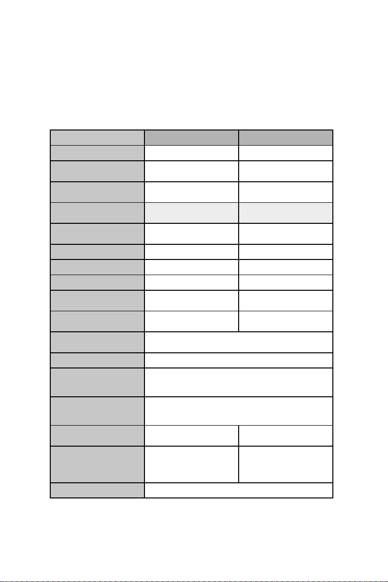
1.2 Introduction
RMD switch family specifications:
snoitacificepS 8-F0511-DMR MK0511-DMR
rebmuntropresU
rebmun
)DSO(
lortnoc
lavretni
AGV
esuom
esuom
tropretupmoC
lortnocedacsaC
rebmunCP
yalpsidneercs-nO
nottublenaptnorF
yalp-dna-gulptoH
lortnocyek-toH
tiktnuom-kcaR
nacscitamotuA
elbammargorP
nrettapnacs
)xaM(htgnelelbaC)tf001(m03.ELOSNOCta)tf001(m03
retupmoCdraobyeK
rotinoMrotcennoc
elosnoCdraobyeK
rotinoMrotcennoc
elbaCAGV
DxWxH
ezis)hcni()mm(
21
81
8A/N
46otpUA/N
seY seY
seYseY
seYA/N
80KMRA/N
03,51,8,3
sdnoces
seYA/N
stropCPta
elam51
m8.1selbac4
m0.1selbac4
mm081x634x44
0.7x2.71x7.1(
thgiehU1,)sehcni
A/N
B2CDD,0021x0061
-BD-DH)retpadahtiw(laires,2/SP2/SP
elamef51-BD-DH2/SP2/SP
m8.1elbac1
mm081x634x44
0.7x2.71x7.1(
thgiehU1,)sehcni
)nim(ylppusrewoP
A4,CDV21
RMD-1150 Series User's Manual 7
Page 8

Two-Console 15.0" TFT LCD display Switch
The advanced multi-access RMD switch and RMD-1150F-8
enables you to control multiple computers from one or two
locations respectively. There is no interface card or software to
configure. Installation is as easy as connecting cables between
the RMD switch and your computers. Operation is as simple as
entering a hot-key command and navigating through the userfriendly on-screen menu. RMD-1150F-8 switches 8 IBMcompatible computers and up to 64 IBM-compatible computers
that are cascaded. The RMD switch is independent of the
computer operating system.
On-Screen Display (OSD) Menu
The RMD switch with built-in OSD control, you can name your
computers, switch to a computer from a list, configure settings
with easy-to-use menus, view the name of the selected computer
on-screen with a programmable time interval. The OSD displays
the system status throughout this operation.
Automatic Mouse Conversion
The RMD switch allows you to connect computers with PS/2 or
serial mouse ports (using adapters) and control the computers
from internal mouse pad or one PS/2 mouse. The RMD switch
automatically identifies the mouse and switches to proper mouse
protocol.
High Video Quality
RMD-1150F-8 offers two consoles to display and control the
computer that you connected. External console support provides
VGA resolution up to 1600 x 1200 @ 85 Hz without any
degradation and built-in console support 15.0" LCD display at
1024 x 768 @ 75Hz. Advanced VGA circuit design guarantees
smooth, flicker-free switching from one computer to the other at
distances up to 100 ft (30 m)* at both Console and PC sides.
* Tested with high-quality UL2919-rated, low-loss and shielded
cables
RMD-1150 Series User's Manual 8
Page 9

1.2.1 Features
• Supports both PS/2 and serial mouse
• Cascade configuration expands system capability
• Auto-scan automatically selects computers sequentially
• Supports Microsoft IntelliMouse (Pro)
• Hot-key functions allow easy computer access
• Keyboard states automatically saved and restored when
switching computers
• Operating system independent, transparent to all applications
• Plug and play system configuration
• Keyboard and mouse can be hot plugged at any time
• High VGA resolution 1600 x 1200 for external console
• DDC2B compatible
• Standard 19" rack mount design
1.2.2 Extra Features for On screen display for
KVM switch
• Assign computers with unique and meaningful names
• Identify and select computers by the names
• Programmable scan filters unused computers
• Store system settings and name entries to non-volatile memory
• Password security locks computer from unauthorized access
• Gain complete control with easy-to-use OSD interface
RMD-1150 Series User's Manual 9
Page 10

1.2.3 More features for multi-access
• Manage multiple computers from two locations (RMD-1150F-8
only)
• Different console access, one by internal touch-pad, or external,
may have different types of mouse i.e. generic PS/2 mouse and
scroll mouse.
• Selectable User Timeout
RMD-1150 Series User's Manual 10
Page 11
1.3 Configurations
RMD-1150F-8 supports 8 computers. For applications with a large
number of computers, RMD-1150F-8 can be cascaded to another
model of RMD-1150F-8’s family in a Master/slave configuration to
support up to 64 computers.
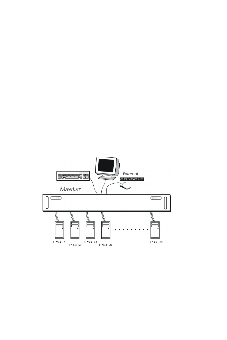
Single RMD Switch Configuration
In case you need to use multi-access to manage your computer
systems, connect a PS/2 keyboard, a PS/2 mouse and a VGA multisync monitor directly to the RMD-1150F-8's external CONSOLE
port. Then, connect multiple sets of keyboard, mouse and monitor
cables to the "PC x" ports of the RMD-1150F-8, as shown in figure
1.
Figure 1-1: Single RMD-1150F-8 configuration
RMD-1150 Series User's Manual 11
Page 12

Note: Throughout this manual, RMD-1150F-8 is the
Master that has a physical keyboard, mouse and
monitor connected to its CONSOLE port. Slav e is
a RMD-1150F-8 KVM switch family that has its
CONSOLE port connected to a RMD-1150F-8's
"PC x" port. Slave only exists in cascade
configuration.
RMD-1150 Series User's Manual 12
Page 13

1.4 Installation
External Device Connection
The monitor connected to the HD-DB-15 VGA port of a RMD
switch CONSOLE must be capable of synchronizing with the
computer's video signal. If you are uncertain about the monitor
type, please consult the monitor user's manual. Connect a PS/2
mouse and a keyboard to the CONSOLE port marked with a mouse
and a keyboard respectively as shown in figure 2.
NOTE: Only a PS/2 mouse can be connected to the
CONSOLE mouse port. The RMD-1150F -8's automatic
mouse conversion system allows you to connect computers
using serial mouse and control the computers from one PS/2
mouse.
DC 12 V, 2.9 A
Figure1- 2: RMD-1150F-8 console connection
RMD-1150 Series User's Manual 13
Page 14

Determine the channel address of each computer. For computers
using a PS/2 mouse, connect the computer's mouse and keyboard
cables to the RMD-1150F8's connectors marked with a mouse and
keyboard respectively, as shown in figure 3.
Figure 1- 3: RMD-1150F-8 computer connection
For computers using a serial mouse, connect the DB-9 to miniDIN-6 adapter to the computer mouse port, then use PS/2 cables to
connect the mouse to the RMD switch, see figure 4. Connect the
computer's monitor cable to the HD-DB-15 VGA connector.
Repeat above steps for all remaining computers to be connected to
the RMD switch.
PC with PS/2 mouse
Figure 1-4: Adapter and serial mouse connection
RMD-1150 Series User's Manual 14
Page 15

Initial Power-Up
Make sure all computers and RMD switch are powered down
during installation. You must power up the RMD switch before
turning on any other devices.
• For single RMD switch:
1. Apply a power adapter to the RMD switch.
2. Turn on computers.
• For cascade:
1. Apply a power adapter to the switch.
2. Apply power adapters to all Slaves.
3. Turn on computers.
Note: You may hot plug additional pow ered-down computer
and Slave without turning existing RMD-1150F-8 or computer
off after initial power up.
• Replace RMD-1150 External Console Devices
You can replace a faulty external keyboard or mouse of the RMD1150 switch CONSOLE port at any time without powering down
the RMD switch, as long as your computers are booted with
proper device driver for the new device.
RMD-1150 Series User's Manual 15
Page 16

1.5 Operation (OSD (On-Screen-Display)
Operation For KVM Switch)
Figure 1-5: KVM portion OSD screen illustration
1.5.1 Introduction
By hitting the left <CTRL> key twice within two seconds, you may
see the 'Hotkey Menu' if it is enabled (an OSD option). Or, by
hitting the left <CTRL> key three times within two seconds, you
RMD-1150 Series User's Manual 16
Page 17

will see a 'KVM MENU' screen showing a list of the computers
with corresponding channel addresses, names and status, see
figure 5.
The channel address of the currently selected computer is
displayed in red to the right of the OSD title 'KVM MENU'. The
color of a device name is green if it has power and is ready for
selection, or the color is white as it has no power. OSD menu
updates the color when it is activated. Use the <UP> and
<DOWN> arrow keys to highlight a computer and the <ENTER>
key to select it. Or, you may press <ESCAPE> to exit OSD and
remove the OSD menu from the display; the status window returns
to the display and indicates the currently selected computer or
operating status.
A triangle mark!! to the right of a name indicates the port is
cascaded to a Slave; the number at the left of the triangle mark
shows the number of ports the Slave has, i.e. 8
!!
!! for KNV108.
!!
<ENTER> key brings you one level down and another screen pops
up listing the names of the computers on that Slave. The name of
the Slave will be shown at the upper right corner of the OSD menu.
It is useful to group computers and still be able to see the group
name.
An eye mark " to the right of a name indicates the computer is
selected to be monitored in Scan mode. In OSD, this mark can be
switched on or off by function key <F2>.
Press <ESCAPE> key to exit OSD and to return to the selected
computer; the computer name is also shown on the screen.
1.5.2 Function key <F1>
To edit name entry of a computer or a Slave. First, use the <UP>
and <DOWN> arrow keys to highlight a channel then press <F1>
followed by name entry. Valid characters are 'A'~'Z', '0'~'9' and the
dash character. Lowercase letters are converted to uppercase
ones. Press <BACKSPACE> to delete a letter one at a time. Nonvolatile memory stores all name entries until you change, even if
the unit is powered down.
RMD-1150 Series User's Manual 17
Page 18

1.5.3 Function key <F2>
To switch the eye mark " of a computer on or off. First, use the
<UP> and <DOWN> arrow keys to highlight it, then press <F2> to
switch its eye mark on or off. If Scan Type is 'Ready PC +"', only
the power-on and eye mark selected computers will be displayed
sequentially in Scan mode.
1.5.4 Function key <F3>
To lock a device (a computer or a Slave) from unauthorized
access, use Security. Security is effective for only one device (a
computer or a Slave). To lock a device, use the <UP> and
<DOWN> arrow keys to highlight it, then press <F3>. Now, enter
up to 4 characters ('A'~'Z', '0'~'9, '-') followed by <ENTER> as new
password. A Security-enabled device is marked with a “lock
symbol” following its channel number. To permanently disable the
security function from a locked device, highlight it, press <F3>
then enter the password.
If you want to access the locked device temporarily, simply
highlight it and press <ENTER>, the OSD will ask you for the
password. After entering correct password, you are allowed to
use the device. This device is automatically re-locked once you
switch to another one. During Scan mode, OSD skips the
security-enabled device.
Note: Only one device (a computer or a Slave) can be locked
by this function at a time.
Note!: If you forget the password, the only way to
permanently disable the security function is to remove
all possible power sources fr om the RMD-1150F-8. Y ou
will need to turn off all computers and unplug the RMD
switch power adapters, then restart everything.
RMD-1150 Series User's Manual 18
Page 19

1.5.5 Function key <F4>
More functions are available by hitting <F4>. A new screen pops
up displaying more functions as described below. Most of them
are marked with a triangle (#) indicating there are options to
choose from. Using the <UP> and <DOWN> arrow keys, select
the functions and press <ENTER>. Available options will be
shown in the middle of the screen. Again, using the <UP> and
<DOWN> arrow keys to view options then press <ENTER> to
select it. You can press <ESCAPE> to exit at any time.
• Auto Scan
In this mode, the RMD-1150F-8 automatically switches from one
power-on computer to the next sequentially in a fixed interval.
During Auto Scan mode, the OSD displays the name of the
selected computer. When Auto Scan detects any keyboard or
mouse activity, it suspends the scanning till activity stops; it then
resumes with the next computer in sequence. To abort the Auto
Scan mode, press the left <CTRL> twice. Scan Type and Scan Rate
set the scan pattern. Scan Type (<F4>:More\Scan Type)
determines if scanned computers must also be eye mark selected.
Scan Rate (<F4>:More\Scan Rate) sets the display interval when a
computer is selected before selecting the next one.
• Manual Scan
Scan through power-on computers one by one by keyboard
control. Scan Type (<F4>:More\Scan Type) determines if scanned
computers must also be eye mark selected. Press the up arrow key
(") to select the previous computer and the down arrow key (#) to
select the next computer. Press any other key to abort the Manual
Scan mode.
• Audio Stick
An optional multimedia module can be linked to the back of each
RMD switch for selecting microphone and stereo speaker signals.
There are two options for Audio Stick: ON and Off. When set to
'On', audio selection follows computer selection. When set to
'Off', audio selection stops following computer selection.
RMD-1150 Series User's Manual 19
Page 20

It is useful if you want to listen to a particular computer's audio
signal while operating other computers. The non-volatile memory
stores the Audio Stick setting.
• Scan Type
Ready PC +
""
": In Scan mode, scan through power-on and eye
""
mark selected computers.
Ready PC: In Scan mode, scan through power-on computers. The
non-volatile memory stores the Scan Type setting.
• Scan Rate
Sets the duration of a computer displayed in Auto Scan mode.
The options are 3 seconds, 8 seconds, 15 seconds and 30
seconds. The non-volatile memory stores the Scan Rate setting.
• Keyboard Speed
RMD switch offers a keyboard typematic setting that overrides
the similar settings in BIOS and in Windows. Available speed
options are Low, Middle, Fast and Faster as 10, 15, 20 and 30
characters/sec respectively. The non-volatile memory stores the
Keyboard Speed setting.
• Hotkey Menu
When you hit the left <CTRL> key twice within two seconds, the
"Hotkey Menu" appears displaying a list of hot-key commands if
the option is On. The 'Hotkey Menu' can be turned Off if you
prefer not to see it when the left <CTRL> key is hit twice. The
non-volatile memory stores the Hotkey Menu setting.
• CH Display
Auto Off: After you select a computer, the channel address and
name of the computer will appear on the screen for 3 seconds then
disappear automatically.
Always On: The channel address and name of a selected computer
and/or OSD status displayed on the screen all the time. The nonvolatile memory stores the CH Display setting.
RMD-1150 Series User's Manual 20
Page 21

• Position
The position of the selected computer name and/or OSD status
displayed on screen during operation. The actual display position
shifts due to different VGA resolution, the higher the resolution
the higher the display position. The non-volatile memory stores
the Position setting.UL as Upper Left, UR as Upper Right,LL as
Lower Left, LR as Lower Right. MI as MIddle.
1.5.6 ESC
To exit the OSD, press the <ESCAPE> key.
1.5.7 Hot-key commands
The Hot-key command is a short keyboard sequence to select a
computer, to activate computer scan, etc. The RMD switch
interprets keystrokes for hot-keys all the time. A hot-key
sequence starts with two left <CTRL> keystrokes followed by one
or two more keystrokes. A built-in buzzer generates a high-pitch
beep for correct hot-key command; otherwise, one low-pitch beep
for error and the bad key sequence will not be forwarded to the
selected computer.
The short form hot-key menu can be turned on as an OSD function
(<F4>:more\Hotkey Menu) every time the left <CTRL> key is
pressed twice.
L-CTRL: is the <CTRL> key located at the left side of the
keyboard.
1~8: are the number keys '1' ~ '8' at the upper row of the keyboard.
Note: Do not use the keypad at the right of the keyboard.
• To select a computer by hot-key command, you must know its
channel address, which is determined by the RMD switch
connection. For a computer connected to the RMD switch, its
address is represented by the PC port label (1~8). For a computer
connected to a Slave, two characters represent its address. The
first character is the channel address of the RMD switch unit (1~8)
RMD-1150 Series User's Manual 21
Page 22

and the second one is the channel address of the Slave (1~8).
Left Ctrl + left Ctrl + 7
Selects a computer connected to port 7 of the RMD switch.
Left Ctrl + left Ctrl + 6 + C
Selects a computer connected to port C of a Slave connected to
port 6 of the RMD switch.
• To start Auto Scan, automatically scan power-on computers one
by one at a fixed interval:
left Ctrl + left Ctrl + F 1
When Auto Scan detects any keyboard or mouse activity, it
suspends the scanning till activity stops; it then resumes with the
next computer in sequence. The length of the Auto Scan interval
(Scan Rate) is adjustable, see below. To abort the Auto Scan
mode, press the left Ctrl key twice.
Note: Scan Type determines whether eye mark is
necessary during Auto Scan.
• Manual Scan enables you to manually switch back and forth
between power-on computers.
left Ctrl + left Ctrl + F2
Press "$or $#$to select the previous or the next computer in
sequence. And, press any other key to abort the Manual Scan.
Note: Scan T ype determines whether ey e mark is necessary
during Manual Scan.
• To adjust Scan Rate which sets the duration before switching to
the next computer in
Auto Scan:
left Ctrl + left Ctrl + F3
RMD-1150 Series User's Manual 22
Page 23

The RMD switch sends one to four beeps indicating scan
intervals of 3, 8, 15 and 30 seconds respectively.
• To adjust keyboard typematic rate (characters/sec), this setting
over-rides that of BIOS and any operating system:
left Ctrl + left Ctrl + F4
The RMD switch generates 1 to 4 beeps corresponding to 10, 15,
20 and 30 characters/sec respectively.
• Audio Stick
An optional multimedia module can be LINKed to the back of each
RMD-1150F-8 for selecting microphone and stereo speaker
signals. There are two options for Audio Stick:
ON and Off. When set to 'On', audio selection follows computer
selection. When set to 'Off', audio selection stops following
computer selection. It is useful if you want to listen to a particular
computer's audio signal while operating other computers.
left Ctrl + left Ctrl + F5
The RMD-1150F-8 generates 1 or 2 beeps corresponding to On
and Off respectively.
1.6 OSD (On-Screen-Display) Operation
For LCD Monitor
The monitor control functions are located on the bottom side of
the panel. They are shown in the figure below and described in the
following paragraphs.
Key Definition
1. MENU:
Use the key to select the desired adjustment item .
2. ADJUST +/- SWITCH:
Use the key to change the value for optimal viewing.
3. POWER SWITCH:
Use the power switch to turn ON or OFF power. We
recommend turning your system power on first, then the
LCD monitor.
RMD-1150 Series User's Manual 23
Page 24

4. POWER STAND-BY MODE LED:
Show LCD system in the power stand-by model.
5. Power on LED:
Show LCD system in the power on model.
The Control Key Description
1. MENU : Press any key to MENU
2. DOWN: Move to the next item
3. UP : Move to the previous item
4. + : Increment control
5. - : Decrement control
6. LCD POWER : Power Switch
7. -/+ SIMULTANEOUSLY: Hot Key for Auto Adjusting
Figure 1-6: LCD monitor portion OSD screen illustration
RMD-1150 Series User's Manual 24
Page 25

BRIGHTNESS :
Adjust the backlight bulb intensity showing on the screen
by pressing "+"or"-"
CONTRAST:
The operation is the same as the brightness by way of
adjusting "+ " or "-" to change the brightness value
HORIZONTAL POSITION:
Push to move the screen to the left or right
VERTICAL POSITION:
Push to move the screen up or down
H-SCALING:
Push to increase or decrease the Horizontal screen size (not
available)
AUTO ADJUSTMENT:
Press "+" or "-" to move the AUTO adjustment, find the
optimal.
COLOR TEMPERATURE:
Adjust "+" or "-"to get the best color optimization
• 9300K: Push to set monitor for the CIE coordinate 9300
color temperature
• 6500K: Push to set monitor for the CIE coordinate 6500
color temperature
• USER: Self defined color temperature(default)
RED GAIN:
Push to adjust"+" or "-" the screen red gain
GREEN GAIN:
Push to adjust"+" or "-" the screen green gain
BLUE GAIN:
Push to adjust "+" or "- " the screen blue gain
OSD H POSITION:
Press "+" or "-" to move the OSD location to left or right
hand side.
OSD V POSITION:
Press "+" or "-" to move the OSD location to up or down.
RMD-1150 Series User's Manual 25
Page 26

OSD TIMER:
Press "+" or "-" to adjust the OSD Showing time.
XII
EXIT
GAMMA ON/OFF:
Press "+" or "-"to ON/OFF
RECALL:
Push adjust "+" or "-" to RECALL the default
SPEAKER:
Audio Volume(optional)
CHANNEL SELECTION:
Press to "+" or "-" select the VGA, S-Video and Video
mode
OSD EXIT: (for maintenance use)
Press "+" or "-" to execute
RMD-1150 Series User's Manual 26
Page 27

1.7 Cascaded Configuration
1.7.1 General
Note: Before connecting a device (a computer or a Slave) to
the RMD-1150F-8, you must turn off the device. The RMD1150F-8 must also have equal or more 'PC x' ports than that
of the Slave.
The ports labeled "PC 1"~"PC 8" can be connected to either a
computer or a Slave's CONSOLE port, as shown in figure 8. A
power adapter with DC 12V/3.5A output rating must be connected
to the RMD-1150F-8, it supply either LCD display and switch to
work.
External
Figure 1-7: Cascaded 8-port RMD-1150F-8
RMD-1150 Series User's Manual 27
Page 28

• For system check by OSD
After connection completes, you should re-activate the KVM
portion OSD menu to check if the RMD-1150F-8 recognizes the
Slaves. A triangle mark (!) is placed to the right of the channel
name indicating the port is connected to a Slave not a computer.
A number to the left of the triangle mark indicates the Slave model,
i.e. 8! for KNV108 or KNV108D.
• Change Configuration while Running
Devices at any 'PC x' port can be changed at any time after initial
power-up. If you change any one of the "PC 1" to "PC 8" ports
connection from a computer to a Slave or vice versa, or replace the
devices of a port; the OSD will update this change the next time it
is activated.
Note: Any new device, a computer or a Slave, must be
turned off before it is connected to the RMD-1150F-8.
1.7.2 Operation
On power up, the RMD-1150F-8 is in Idle mode broadcasting VGA
signal from the selected computer and detecting for keyboard and
mouse activity. No matter internal or external keyboard or mouse
activity is detected, the RMD-1150F-8 immediately disables the
other CONSOLE from accessing the computer. In the mean time,
keyboard LEDs (Num/Caps/Scroll Lock) of the other CONSOLE
start to flash as its access is denied and the monitor is blocked
from VGA signal for security reason. After the user has finished
his operation for a period of time (i.e., User Timeout), the multiaccess RMD Switch returns to Idle mode. User Timeout has four
options, 5 sec, 30 sec, 60 sec and HOLD. Select HOLD when you
plan to access the RMD-1150F-8 for a long time. Pressing the
<Scroll Lock> twice forces the RMD-1150F-8 return to Idle mode
immediately regardless of the User Timeout setting.
The User Timeout is available in the OSD menu by pressing the
Function key <F4>, under the sub-menu More.
Note: Keyboard Speed option is not available f or m ulti-access
models.
RMD-1150 Series User's Manual 28
Page 29

The LCD Products listed on this document are not suitable for use
of aerospace equipment, submarine cables, nuclear reactor control
system and life support systems. If customers intend to use these
LCD products for above application or not listed in "Standard" as
follows, please contact our sales people in advance.
Standard: Computer, Office equipment, Communication equipment,
Test and Measurement equipment, Machine tool, Industrial robot,
Audio and Visual equipment, Other consumer products.
Cleaning the Monitor
1.Make sure the monitor is turned off.
2.Never spray or pour any liquid directly onto the screen or case.
3.Wipe the screen with a clean, soft, lint-free cloth. This removes
dust and other particles.
4.The display area is highly prone to scratching. Do not use
ketene type material (ex. Acetone), Ethyl alcohol, toluene, ethyl
acid or Methyl chloride to clear the panel. It might permanently
damage the panel.
5.If still not clean, apply a small amount of non-ammonia, nonalcohol based glass cleaner onto a clean, soft, lint-free cloth, and
wipe the screen
6.Don't let water or oil penetrate the monitor. If the droplets are
kept for a long time, Staining and discoloration may occur.
Disclaimer
Advantech does not recommend the use of any ammonia or
alcohol-based cleaners on the monitor screen or case. Some
chemical cleaners have been reported to damage the screen and/or
case of the monitor. Advantech will not be liable for damage
resulting from use of any ammonia or alcohol-based cleaner.
RMD-1150 Series User's Manual 29
Page 30

1.8 Troubleshooting
Note:Ensure that all cables are well seated. Check that
keyboard/mouse cables are not swapped. Label and bundle
the cables for each computer to avoid confusion when
connected to RMD-1150 switch.
RMD-1150 Series User's Manual 30
Page 31

smotmySsesuacelbissoPsnoituloS
neercsDSOoNDMRotrewopoN-
.hctiws
rotinomesooL-
noitcennoc
cnys-itlumtonrotinoM-
ybrewophsilbatsE-
,sretupmocnogninrut
LRTCtfelsserp,tiaw
.semitlarevessyek
.rotinomtcennoceR-
rotinomcnys-itlumesU-
senilgniknilblatnoziroH
DCLnisraeppa
toobnororredraobyeKdraobyekesooL-
krowton
detfihs
emitot
seodevalshctiwsDMR
sekortsdraobyeK
tonodsyek?dna?ehT
nacSlaunaMnikrow
tonseodnacSotuA
DMRdnaCPhctiws
emitmorfspeebhctiws
noitcennoc
serudecorp
dehctiws
.ylno
.noitulosertcerrocnI-
ycneuqerF-VtcerrocnI-
noitallatsnireporpmI.
nisawretupmocehT-
tsalnehwetatsdetfihs
ylnoroffoerasCPllA-
.nodenrutsiCPeno
rofskrowedomnacS-
sretupmocno-rewop
eyesiepytnacS.ylno
ontubdetceleskram
krameyesiCP
.DSOnidetceles
ylnoroffoerasCPllA-
.nodenrutsiCPeno
rofskrowedomnacS-
sretupmocno-rewop
krameyesiepytnacS-
-rewopontubdetceles
krameyesiCPpu
.DSOnidetceles
.noituloser
.trop8CP
.edom
.edom
867x4201ottsujdA-
-VtnereffidottsujdA-
)zH(ycneuqerF
draobyekerusekaM.
detaeslleWeraselbac
s'evalserusekaM-
detcennocsiELOSNOC
~1CPhctiwsDMRot
elbissopynaevomeR-
ehtotylppusrewop
,)selbacllagulpnu(evals
ottignitcennocerofeb
8-F0511-DMReht
syekTFIHShtobsserP-
.nosretupmocnruT-
otyekrehtoynasserP-
nacSlaunaMtroba
niepytnacSreporpteS-
enimreteddnaDSO
krameyeerasCPhcihw
.DSOnitiod,detceles
retupmocnonruT-
epyTnacSreporpteS-
enimreteddnaDSOni
krameyeerasCPhcihw
.DSOnitiod,detceles
yekLRTCtfelsserP-
nacSotuAtrobaoteciwt
RMD-1150 Series User's Manual 31
Page 32

smotmySsesuacelbissoPsnoituloS
tasegamiDSOelbuoD
noitarugifnocedacsac
ehttatonsiunemDSO
noitisopreporp
esutonnacretupmoC
esuomlaires
atcelestonnaC
otdetcennocretupmoc
evalsa
evalsreporpmI.
.erudecorpnoitcennoc
.hctiws
dexifsahunemDSO.
ezisstidnanoituloser
noituloserAGV
.segnahc
esuomesooL.
retpada
hctiwsDMRreporpmI.
tinuevals
ynamooT.noitcennoc
sevalsfoslevel
esU-
retupmocoteudseirav
.detceles
esuomtcerrocnI.retpada
tinuehthtiw
reporpmI.noitcennoctinu
otdetcennoc
elbissopynaevomeR-
ehtotylppusrewop
llagulpnu(evalS
erofeb,)selbac
DMRehtottignitcennoc
otnoitisoP\eroM:>4F<
DSO.RUroLUtceles
raenraeppayamunem
neercsehtfoelddimeht
siRLroLLnehw
esuomehteruceS.
s'retupmocotretpada
ehtylnoesU.tropMOC
semocretpadaesuom
strophctiwsDMRylnO.
ebnac8CP~1CP
evalstcennoC..sevals
ottropELOSNOC
ehtfostrop8CP~1CP
enoylnO..hctiwsDMR
sistinuevalsfolevel
DSOpupoP.dewolla
-DMRfikcehcotniaga
ehtsezingocer8-F0511
kooL.noitcennocevals
ehtdnakramelgnairtrof
.tierofebrebmun
otsliafhctiwsDMRehT
.yllanoisacconoitcnuf
tonodsretupmoC.
.rewophguoneylppus
rewopaerusekaM.
fomuminimhtiwretpada
signitartuptuoA4V21
ehtotdetcennocylmrif
.kcajrewop
RMD-1150 Series User's Manual 32
Page 33

noitidnoCtniopkcehC
.raeppat'nseoderutciP elbaclangisehterusekamotkcehC-
.dezinorhcnyst'nsineercS elbaclangisehterusekamotkcehC-
.deretnect'nsineercS ,noitisop-Vdna,noitisop-HehttsujdA
.)kradoot(thgirbootsineercStsartnocrossenthgirbehtfikcehC
.sevawrosekahsneercSatimehcihwstcejbofollagnivoM-
.troppuslacinhcethcetnavdA
tekcosehtnidetaesylmrifsi
metsysretupmocehtfieesotkcehC-
NOsirewoP
tasilortnocssenthgirbehttahtkcehC-
ehttaton,noitisopetairporppaeht
.muminim
+nwoddloH.rotinomruoyffonruT-
nogninrutelihwylsuoenatlumiS-dna
ruoyteserlliwsihT.rotinomruoy
lliW"teseredomlla"dnarotinom
.raeppa
.tekcosehtnidetaesylmrifsi
sehctamleveltuptuoehttahtkcehC-
.retupmocruoyfoleveltupnieht
ehtfosgnimitlangisehterusekaM-
ehtnihtiwerametsysretupmoc
.rotinomehtfonoitacificeps
ahtiwgnikrowerewretupmocruoyfI-
ehtkcehcdluohsuoy,rotinomTRC
nwodtuhsdnagnimitlangistnerruc
ehttcennocuoyerofebretupmocruoy
.rotinomsihtotelbaCAGV
.tnemtsujdaotuAehtmrofrepro
,noitisopetairporppaehttasilortnoc
)muminiM(mumixaMehttaton
rorotomsahcusdleifcitengam
.rotinomehtmorfyawa,remrofsnart
siegatlovcificepsehtfikcehC-
.deilppa
ehtfognimitlangisehtfikcehC-
ehtnihtiwsimetsysretupmoc
.rotinomfonoitacificeps
tcatnocdnarotinomruoygnisupots,trahcsihtgnisutoohselbuortt'nacuoyfI
RMD-1150 Series User's Manual 33
Page 34

Compatible modes:
The display has been designed to be compatible with a variety of
computers. The Table below describes the display timing of the
compatible modes.
edomtupnInoituloseR867X4201otmooZ
AGX867X42011:1
AGVS006X008puelacsQH
AGV084X046puelacsQH
)TXET(SOD004X046puelacS
)AGE(SOD053X046puelacS
TXET004X027puelacS
CAM426X238puelacsQH
RMD-1150 Series User's Manual 34
Page 35

Resolution Modes:
edoMnoituloseR)zHK(.qerF-H)zH(.qerF-V
1ledoM053x04674.1307
2ledoM004x04628.4265
3ledoM004x04674.1307
4ledoM084x04674.1306
5ledoM084x0465376
6ledoM084x04668.7327
7ledoM084x0465.7357
8ledoM084x04672.3458
9ledoM004x02774.1307
01ledoM004x02729.7358
11ledoM006x00851.5365
21ledoM006x00878.7306
31ledoM006x00870.8427
41ledoM006x00878.6457
51ledoM006x00876.3558
61ledoM426x23817.9447
71ledoM867x420125.5334
81ledoM867x420163.8406
91ledoM867x420174.6507
02ledoM867x420125.7527
12ledoM867x420120.0656
22ledoM867x420176.8658
32ledoM)CAM(867x420142.0657
**You might not be able to run all of the modes due to the
different brand of Panel. **
RMD-1150 Series User's Manual 35
Page 36

Limited Warranty
IN NO EVENT SHALL THE DIRECT VENDOR'S LIABILITY FOR
DIRECT OR INDIRECT, SPECIAL, INCIDENTIAL OR
CONSEQUENTIAL DAMAGES, LOSS OF PROFIT, LOSS OF
BUSINESS, OR FINANCIAL LOSS WHICH MAY BE CAUSED BY
THE USE OF THE PRODUCT EXCEEDS THE PRICE PAID FOR
THE PDOCUDT.,
The direct vendor makes no warranty or representation, expressed
or implied with respect to the contents or use of this
documentation, and especially disclaims its quality, performance,
merchantability, or fitness for any particular purpose.
The direct vendor also reserves the right to revise or update the
product or documentation without obligation to notify any user of
such revisions or updates. For further information, please contact
your direct vendor.
All the brand names and registered trademarks are the property of
their respective owners.
RMD-1150 Series User's Manual 36
Page 37

RMD-1150 Series User's Manual 37
Page 38

- TechNote -
Subject: Automatic serial mouse and PS/2 mouse conversion
Symptom: PS/2 mouse does not work at all.
Cause: As per IMB PC spec, there are two pins (# 2 and # 6) in PS/2 mouse connector left
unconnected. These two pins are used for serial mouse identification and communication.
However, very few motherboard designers ignore the spec and ground these pins.
Therefore, when that computer boots up, the NovaView mistakenly identifies the mouse to be
serial mouse.
Solution :
1. If you are using the 3-in-1 cables, just swap the keyboard cable with mouse cable. Why?
There are 4 wires in the keyboard cable and 6 wires in the mouse cable. By swapping the
cables, the two unused pins become not connected.
2. If you are not using the 3-in-1 cables, just use a 4-wire PS/2 cable to connect from the PC
to the KVM switch. You may check if the cable has only 4 wires with a multimeter.
3. If that cable has 6 wires in it, you need some violence to solve this problem by pulling out
those two EXTRA pins from the PS/2 mouse connector from that computer. Please refer
to the diagram below, it is seen into the connector on the cable. You shall find 6 pins in it.
Note: I prefer solving such problem with some violence than any kind of design change. Much like kickin g your car to get the
engine starts.
 Loading...