

Page 1

ADAM-5000 Series
I/O Module
User's Manual
Copyright Notice
This document is copyrighted, 1997, by Advantech Co., Ltd. All rights are
reserved. Advantech Co., Ltd., reserves the right to make improvements to the
products described in this manual at any time without notice.
No part of this manual may be reproduced, copied, translated or transmitted in
any form or by any means without the prior written permission of Advantech Co.,
Ltd. Information provided in this manual is intended to be accurate and reliable.
However, Advantech Co., Ltd. assumes no responsibility for its use, nor for any
infringements upon the rights of third parties, which may result from its use.
Acknowledgments
ADAM is a trademark of Advantech Co., Ltd.
IBM and PC are trademarks of International Business
Machines Corporation.
Second Edition
March 2005
Page 2

I/O Module Introduction
Table of Contents
Chapter 1 Introduction ….……..................…..................…………. 1-1
Chapter 2 Analog Input Modules..................….................…....... 2-1
2.1 ADAM-5013 3-channel RTD input module…............................2-2
2.2 ADAM-5017 8-channel analog inpu t mo dul e …….…............... 2-5
2.3 ADAM-5017H 8-channel high speed analog input module…. 2-8
2.4 ADAM-5018 7-channel thermocouple input module ………..2-13
Chapter 3 Analog Output Modules .............................................. 3-1
3.1 ADAM-5024 4- channel analog ou tput module...…...................3-2
Chapter 4 Digital Input/Output Modules..................…....................4-1
4.1 ADAM-5050 16-channel universal digital I/O module...............4-2
4.2 ADAM-5051 series digital input module.........….......................4-5
4.2.1 ADAM-5051(D) 16-channel digital input module …….….. ....4-5
4.2.2 ADAM-5051S 16-channel Isolated Digital Input Module w/LED ..….4- 7
4.3 ADAM-5052 8-channel isolated digital input module…...........4-9
4.4 ADAM-5055S 16-channel Isolated Digital I/O Module with LED……...4-11
4.5 ADAM-5056(D) series digital output module w/ LED……........4-13
4.5.1 ADAM-5056(D) 16-channel digital output module w/LED..4-1 3
4.5.2 ADAM-5056S 16-channel Isolated Digital Output Module w/ LED.4-14
4.5.3 ADAM-5056SO 16-channel Isolated Digital Output Module wLED4- 16
4.6 Relay Output Modules ………….…..................….................…4-18
4.6.1 ADAM-5060 relay output module……………….….......…….4-18
4.6.2 ADAM-5068 relay output module……………………………..4-19
4.6.3 ADAM-5069 relay output module……………………………..4-21
4.7 Counter/Frequency Module………………………………..……4-22
4.7.1 ADAM-5080 4-channel Counter/Frequency Module………..4.22
ADAM-5000 Series I/O Module User’s Manual
Page 3

I/O Module Introduction
Chapter 5 Serial Communication Module………..….................... 5-1
5.1 ADAM-5090 4-port RS-232 Communication Module................5-2
Chapter 6 Analog I/O Modules Calibration.................................. 6-1
6.1 Analog input module calibration……………………………….. 6-2
6.2 ADAM-5013 RTD Input Resistance Calibration……………….. 6-7
6.3 Analog output module calibration .......………………………… 6-9
ADAM-5000 Series I/O Module User’s Manual
Page 4

Introduction 1
Page 5

Introduction
This manual introduces the detail specifications functions and
application wiring of each ADAM-5000 I/O modules. To organize an
ADAM-5510 Series Controller, you need to select I/O modules to interface
the main unit with field devices or processes that you have previously
determine d. Advantec h provid es 19 types of ADAM-5000 I/O modules for
vario us a pp li ca ti on s s o fa r. Following ta bl e i s th e I / O modules support list we
provided for user’ s choice.
Module Name Specification Reference
ADAM-5013 3-ch. RTD input Isolated
ADAM-5017 8-ch. AI Isolated
Analog I/O
Digital I/O
Relay Output
Counter/Frequency ADAM-5080 4-ch. Counter/Frequency Isolated
Serial I/O ADAM-5090 4-port RS232 Non-isolated
ADAM-5017H 8-ch. High speed AI Isolated
ADAM-5018 7-ch. Thermocouple input Isolated
ADAM-5024 4-ch. AO Isolated
ADAM-5050 7-ch. D I/O Non-isolated
ADAM-5051 16-ch. DI Non-isolated
ADAM-5051D 16-ch. DI w/LED Non-isolated
ADAM-5051S 16-ch. Isolated DI w/LED Isolated
ADAM-5052 8-ch. DI Isolated
ADAM-5055S 16-ch. Isolated DI/O w/LED Isolated
ADAM-5056 16-ch. DO Non-isolated
ADAM-5056D 16-ch. DO w/LED Non-isolated
ADAM-5056S 16-ch. Isolated DO w/LED Isolated
ADAM-5056SO 16-ch. Iso. DO w/LED (source) Isolated
ADAM-5060 6-ch. Relay output Isolated
ADAM-5068 8-ch. Relay output Isolated
ADAM-5069 8-ch. Relay output Isolated
Table 1-1: I/O Module Support List
2
ADAM 5000 IO modules User’s Manual
1-
Page 6

Analog Input Modules 2
Page 7
Analog Input module
Analog input modules use an A/D converter to convert sensor voltage,
current, thermocouple or RTD signals into digital data. The digital data is then
translated into engineering units. The analog input modules protect your
equipment from ground loops and power surges by providing opto-isolation
of the A/D input and transformer based isolation up to3,000 V
.
DC
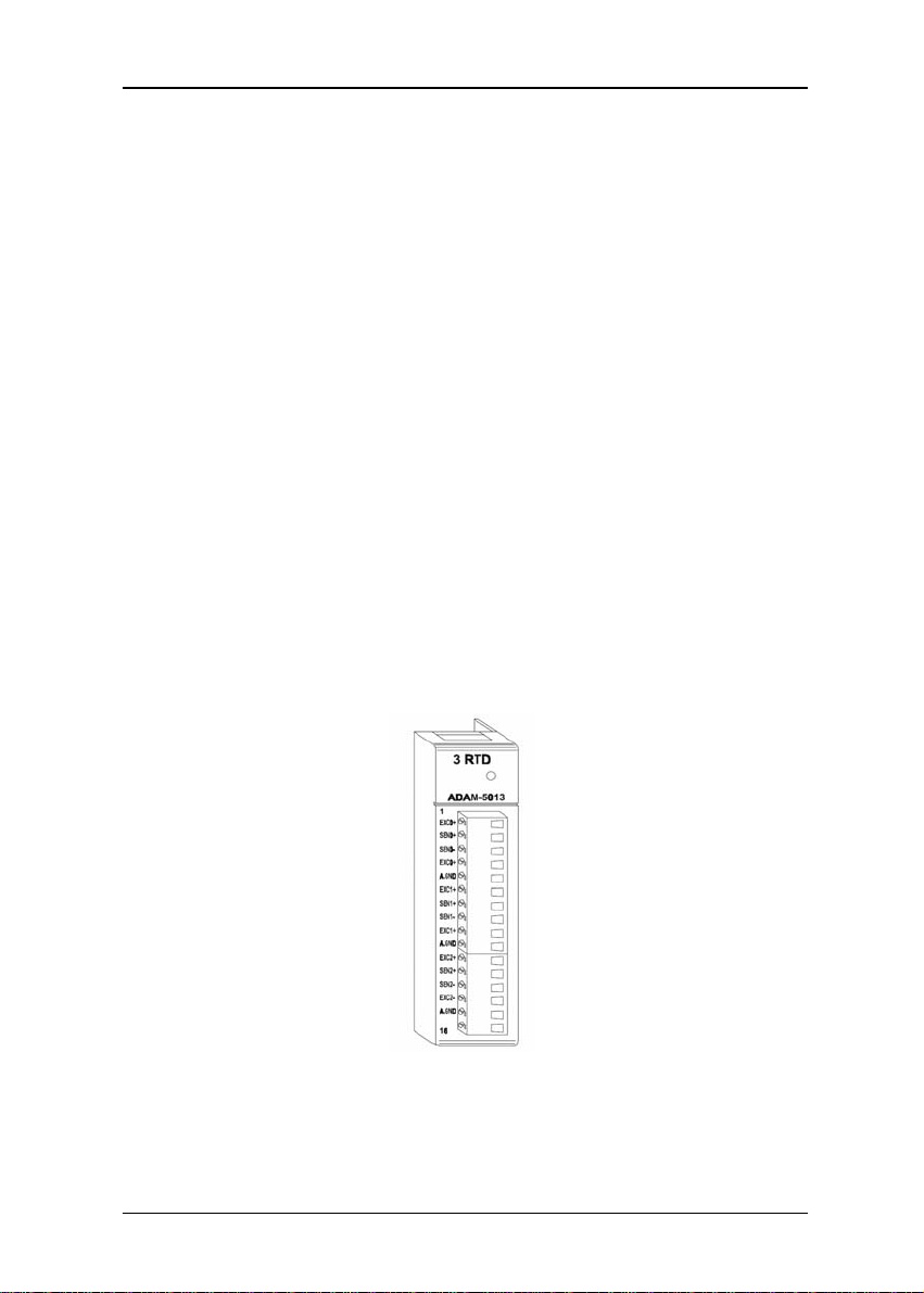
2.1 ADAM-5013 3-channel RTD input module
The ADAM-5013 is a 16-bit, 3-channel RTD input module that features
programmable input ranges on all channels. This module is an extremely
cost-effective solution for industrial measurement and monitoring
applications. Its opto-isolated inputs provide 3,000 V
the analog input and the module, protecting the module and peripherals
from damage due to high input line voltage.
Note: Owing to the conversion time required by the A/D converter, the
initialization time of each ADAM-5013 module is 5 seconds. Thus the
total initialization time will be about 20 seconds if all 4 I/O slots in
an ADAM-5000 main unit contain ADAM-5013 modules.
of isolation between
DC
Figure 2-1: ADAM-5013 module front al view
2
ADAM 5000 IO modules User’s Manual
2-
Page 8
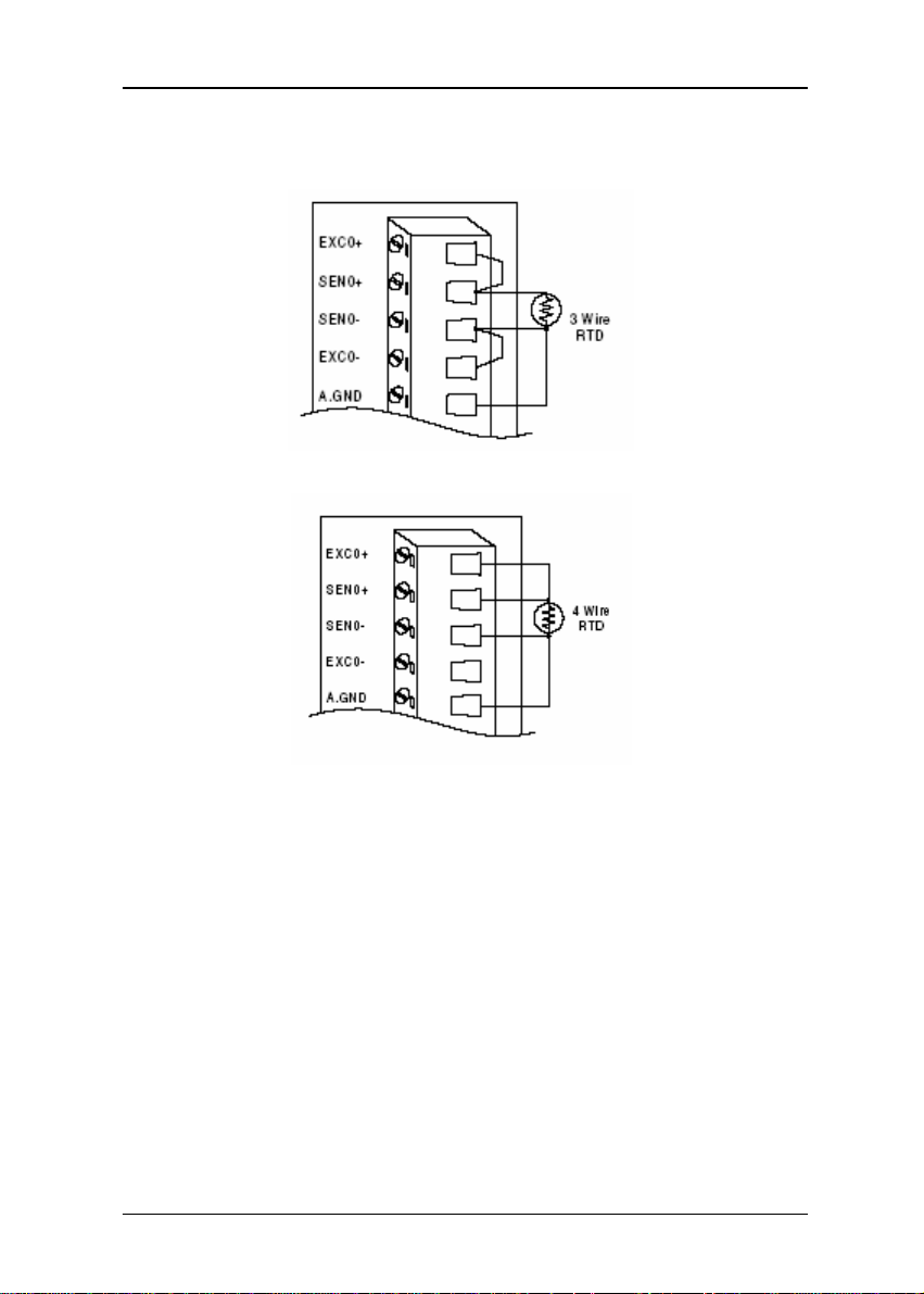
Application wiring
Chapter 2
Figure 2 - 2: RTD inputs
-3
2
Page 9

Analog Input module
Technical specifications of AD AM-5013
Analog input channels
three
Input type
RTD type and temperature
range
Isolation voltage
Sampling rate
Input impedance
Bandwidth
Input connections
Accuracy
Zero drift
Span drift
CMR@50/60 Hz
Pt or Ni RTD
Pt -100 to 100°C a=0.00385
Pt 0 to 100°C a=0.00385
Pt 0 to 200°C a=0.00385
Pt 0 to 600°C a=0.00385
Pt -100 to 100°C a=0.00392
Pt 0 to 100°C a=0.00392
Pt 0 to 200°C a=0.00392
Pt 0 to 600°C a=0.00392
Ni -80 to 100°C
Ni 0 to 100°C
3000 V
DC
10 samples/sec (total)
2 MΩ
13.1 Hz @ 50 Hz, 15.72 Hz @ 60 Hz
2, 3 or 4 wire
± 0.1% or better
± 0.015 °C/°C
± 0.01 °C/°C
150 dB
NMR@50/60 Hz
Power consumption
Table 2-1: Technical specifications of ADAM-5013
4
ADAM 5000 IO modules User’s Manual
2-
100 dB
1.2 W
Page 10
Chapter 2
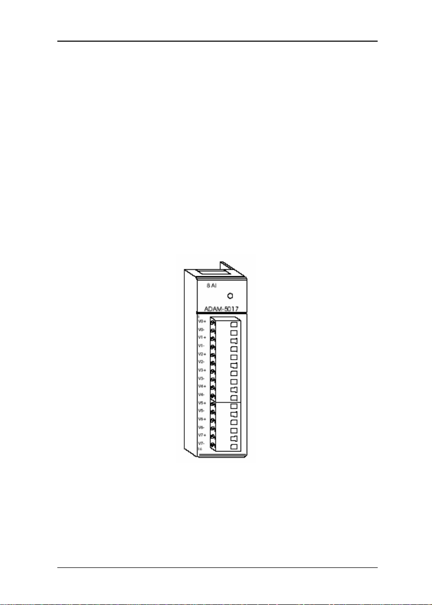
2.2 ADAM-5017 8-channel analog input module
The ADAM-5017 is a 16-bit, 8-channel analog differential input module
that provides programmable input ranges on all channels. It accepts
millivolt inputs (±150mV, ±500mV), voltage inputs (±1V, ±5V and ±10V) and
current input (±20 mA, requires 125 ohms resistor). The module provides
data to the host computer in engineering units (mV, V or mA). This module
is an extremely cost-effective solution for industrial measurement and
monitoring applications. Its opto-isolated inputs provide 3,000 V
isolation between the analog input and the module, protecting the module and
peripherals from damage due to high input line volt- age. Additionally, the
module uses analog multiplexers with active over- voltage protection. The
active protection circuitry assures that signal fidelity is maintained even
under fault conditions that would destroy other multiplexers. This module
can withstand an input voltage surge of 70 Vp-p with ±15 V supplies.
DC
of
Figure 2-3: ADAM-50 17 m odul e fr ontal view
-5
2
Page 11
Analog Input module
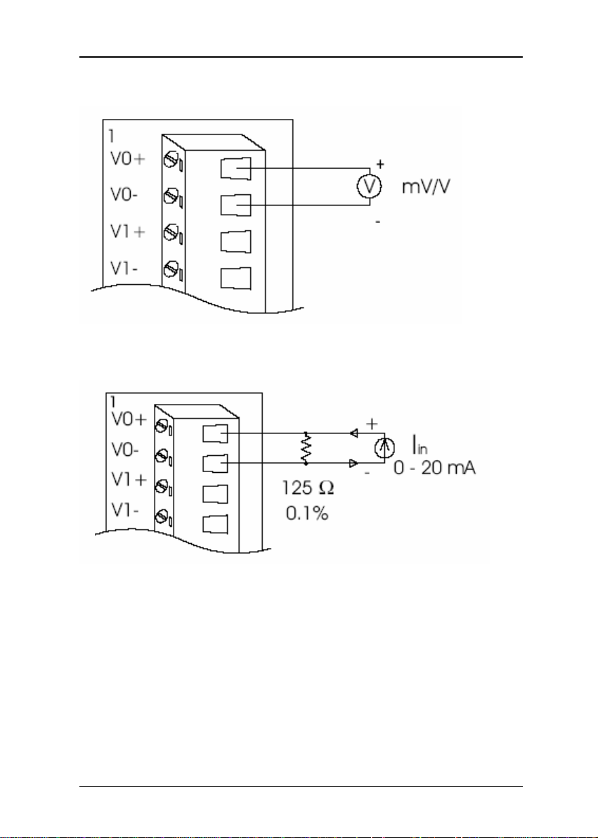
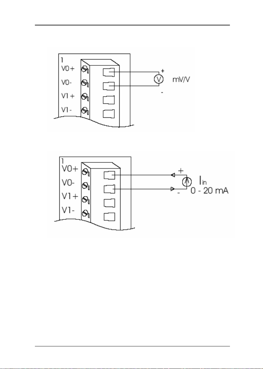
Application wiring
Figure2-4: Millivolt and volt input
Figure 2-5: Process current input
Note: To keep measurement accuracy please short the channels that
are not in use.
6
ADAM 5000 IO modules User’s Manual
2-
Page 12

Technical specifications of AD AM-5017
Analog Input Channels
Input Type
Chapter 2
Eight differential
mV, V, mA
Input Range
Isolation Voltage
Sampling Rate
Analog Input Signal Limit
Max. allowable voltage difference
between two connectors in a
module
Input Impedance
Bandwidth
Accuracy
Zero Drift
Span Drift
CMR @ 50/60 Hz
Power Requirements
Power Consumption
Table2-2: Technical specifications of ADAM-5017
± 150 mV, ± 500 mV, ± 1 V, ± 5 V, ± 10 V and ± 20 mA
3000 V
DC
10 samples/sec (total)
15 V max.
15 V max.
2 Mohms
13.1 Hz @ 50 Hz, 15.72 Hz @ 60 Hz
± 0.1% or better
± 1.5 µV/°C
± 25 PPM/°C
92 dB min.
+ 10 to + 30 V
1.2 W
DC (non-regulated)
-7
2
Page 13

Analog Input module
2.3 ADAM-5017H 8-channel high speed analog input module
The ADAM-5017H is a 12-bit plus sign bit, 8-channel analog differential
input module that provides programmable input ranges on each channel. It
accepts millivolt inputs (± 500 mV, 0-500 mV), voltage inputs (±1 V, 0-1V, ±2.5 V,
0-2.5 V, ±5 V, 0-5 V, ±10 V and 0-10 V) and current inputs (0-20 mA and 4-20 mA;
requires a 125 ohms resistor). The module provides data to the host
microprocessor in engineering units (mV, V or mA) or two’s complement
format.
Its sampling rate depends on the data format received: up to 100 Hz
(total). Space is reserved for 125-ohm, 0.1%, 10 ppm resistors (See Figure2-9).
Each input channel has 3000 V
analog input line and the module, protecting the module and peripherals from
high input line voltages. Addition- ally, the module uses analog multiplexers
with active over-voltage protection. The active protection circuitry assures
that signal fidelity is main- tained even under fault conditions that would
destroy other multiplex- ers. The analog inputs can withstand a constant 70
Vp-p input with ±15V supplies.
of optical isolation between the outside
DC
Figure 2-6: ADAM -5017H module fr ontal view
8
ADAM 5000 IO modules User’s Manual
2-
Page 14
Chapter 2
Application wiring
Figure 2-7 : Millivolt a nd volt input
Figure 2- 8 : Process current input
-9
2
Page 15
Analog Input module
Figure 2-9: Locat ions of 12 5-ohm resist ors
Note: To maintain measurement accuracy please short channels not in
use.
10
ADAM 5000 IO modules User’s Manual
2-
Page 16

Technical specifications of AD AM-5017H
Analog Input Channels
ADC Resolution
Type of ADC
Isolation Voltage
Sampling Rate
8 differential
12 bits, plus sign bit
Successive approximation
DC
3000 V
100 Hz
Chapter 2
Input Impedance
Signal Input Bandwidth
Analog Signal Range
Analog Signal Range for any two
measured Pins
Power Requirements
Power Consumption
Table 2-3: Technical specifications of ADAM-5017H
20 Mohms (voltage inputs); 125 ohms (current
inputs)
1000 Hz for both voltage inputs and current inputs
±15 V max.
±15 V max.
+10 to +30 V
1.8 W
DC (non-regulated)
-11
2
Page 17

Analog Input module
Input
Range
0 ~ 10 V 0 ~ 11 V ±1 LSB ±2 LSB ±1 LSB ±2 LSB 17 µV/°C 50
Voltage
Inputs
0 ~ 5 V 0 ~ 5.5 V ±1 LSB ±2 LSB ±1.5 LSB ±2 LSB 16 µV/°C 50
0 ~ 2.5 V 0 ~ 2.75 V ±1 LSB ±2 LSB ±1.5 LSB ±2 LSB 20 µV/°C 55
0 ~ 1 V 0 ~ 1.375 V ±1 LSB ±2.5 LSB ±2 LSB ±2.5 LSB 20 µV/°C 60
0 ~ 500 mV 0 ~ 687.5
± 10 V ±11 V ±1 LSB ±2 LSB ±1 LSB ±2 LSB 17 µV/°C 50
± 5 V ±0 ~ 5.5 V ±1 LSB ±2 LSB ±1.5 LSB ±2 LSB 17 µV/°C 50
± 2.5 V ±0 ~ 2.75 V ±1 LSB ±2 LSB ±1.5 LSB ±2 LSB 20 µV/°C 55
± 1 V ±0 ~ 1.375 V ±1 LSB ±2.5 LSB ±2 LSB ±2.5 LSB 20 µV/°C 60
± 500 mV ±0 ~ 687.5
0 ~ 20 mA 22 mA ±1 LSB ±1 LSB ±1.5 LSB ±2 LSB nA/°C ppm/°C 5.3 µΑ Current
Inputs
4 ~ 20 mA 22 mA ±1 LSB ±1 LSB ±1.5 LSB ±2 LSB nA/°C ppm/°C 5.3 µΑ
With
Overranging
mV
mV
Offset
Error @
25°C
Offset
Gain
Gain
Error @ -
Error @
10 to
25°C
+70°C
- ±5 LSB ±3 LSB ±3.5 LSB 20 µV/°C 67
- ±5 LSB ±3 LSB ±3.5 LSB 20 µV/°C 67
Error @ 10 to
+70°C
Offset
Drift
Table 2-4: ADAM-5017H input signal ranges
Gain
Drift
ppm/°C
ppm/°C
ppm/°C
ppm/°C
ppm/°C
ppm/°C
ppm/°C
ppm/°C
ppm/°C
ppm/°C
Display
Resolution
2.7 mV
1.3 mV
0.67 mV
0.34 mV
0.16 mV
2.7 mV
1.3 mV
0.67 mV
0.34 mV
0.16 mV
12
ADAM 5000 IO modules User’s Manual
2-
Page 18
Chapter 2
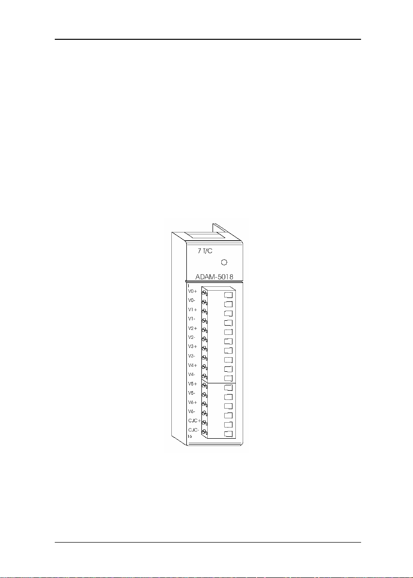
2.4 ADAM-5018 7-channel thermocouple input module
The ADAM-5018 is a 16-bit, 7-channel thermocouple input module that
features programmable input ranges on all channels. It accepts millivolt
inputs (±15 mV, ±50 mV, ±100 mV, ±500 mV), voltage inputs (±1 V, ±2.5 V),
current input (±20 mA, requires 125 ohms resistor) and thermocouple input
(J, K, T, R, S, E, B).
The module forwards the data to the host computer in engineering units
(mV, V, mA or temperature °C). An external CJC on the plug-in terminal is
designed for accurate temperature measurement.
Figure 2-10 : A DAM -50 18 m odul e fr ont al view
-13
2
Page 19
Analog Input module
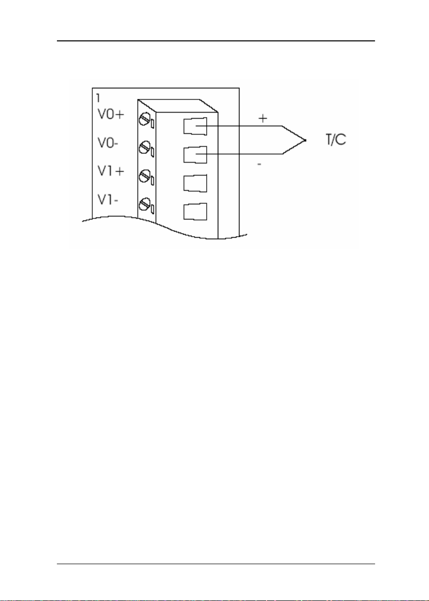
Application wiring
Figure 2-11: Thermocouple input
14
ADAM 5000 IO modules User’s Manual
2-
Page 20

Technical specifications of AD AM-5018
Analog Input Channels
Input Type
Seven differential
mV, V, mA, Thermocouple
Chapter 2
Input Range
T/C Type and Temperature Range
Isolation Voltage
Sampling Rate
Input Impedance
Bandwidth
Accuracy
Zero Drift
Span Drift
CMR @ 50/60 Hz
Power Consumption
Table 2-5: Technical specifications of ADAM-5018
± 15 mV, ± 50 mV, ± 100 mV, ± 500 mV, ± 1 V, ± 2.5
V and ± 20 mA
JKTERSB 0 to 760 °C 0 to 1370 °C -100 to
DC
3000 V
10 samples/sec (total)
2 Mohms
13.1 Hz @ 50 Hz, 15.72 Hz @ 60 Hz
± 0.1% or better
± 0.3 µV/°C
± 25 PPM/°C
92 dB min.
1.2 W
400 °C 0 to 1400 °C 500 to 1750
°C 500 to 1750 °C 500 to 1800
°C
-15
2
Page 21

Analog Output Module 3
Page 22
Analog Output Module
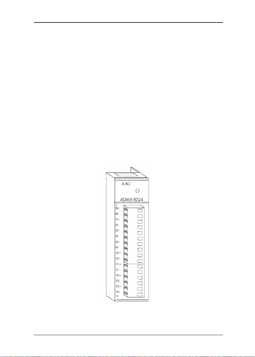
3.1 ADAM-5024 4-channel analog output module
The ADAM-5024 is a 4-channel analog output module. It receives its
digital input through the RS-485 interface of the ADAM-5510 system
module from the host computer. The format of the data is engineering units.
It then uses the D/A convert er controlled by t he system module t o convert the
digital data into output signals.
You can specify slew rates and start up currents through the
configuration software. The analog output can also be configured as
current or voltage through the software utility. The module protects your
equipment from ground loops and power surges by providing opto-isolation
of the D/A output and t ransfo rmer based i solati on up to 500 V
.
DC
Slew rate
The slew rate is defined as the slope indicated the ascending or
descending rate per second of the analog output from the present to the
required.
Figure 3-1: ADAM-5024 module frontal view
2
ADAM 5000 IO modules User’s Manual
3-
Page 23

Application wiring
Chapter 3
Technical specifications of AD AM-5024
Analog Output Channels
Output Type
Output Range
Isolation Voltage
Output Impedance
Accuracy
Zero Drift
Resolution
Span Temperature Coefficient
Programmable Output Slope
Current Load Resistor
Power Consumption
Table 3-1: Technical specifications of ADAM-5024
Figure 3-2: Analog output
Four
V, mA
0-20mA, 4-20mA, 0-10V
3000 Vdc
0.5 Ohms
±0.1% of FSR for current output ±0.2% of FSR
for voltage output
Voltage output: ±30 µV/ºC Current output: ±0.2
µA/ºC
±0.015% of FSR
±25 PPM/ºC
0.125-128.0 mA/sec 0.0625-64.0 V/sec
0-500 Ohms (source)
2.5W (Max.)
3-3
Page 24

Digital Input/Output Modules 4
Page 25

Analog Input module
4.1 ADAM-5050 16-channel universal digital I/O module
The ADAM-5050 features sixteen digital input/output channels. Each
channel can be independently configured to be an input or an output
channel by the setting of its DIP switch. The digital outputs are open
collector transistor switches that can be controlled from the ADAM-5000.
The switches can also be used to control solid-state relays, which in turn can
control heaters, pumps and power equipment. The ADAM-5000 can use the
module’s digital inputs to determine the state of limit or safety switches, or to
receive remote digital signals.
Warning!
A channel may be destroyed if it is subjected
to an input signal while it is configured to be
an output channel.
Figure 4-1: Dip switch setting for digital I/O channel
2
ADAM 5000 IO modules User’s Manual
4-
Figure 4-2: ADAM-5050 module frontal view
Page 26

Chapter 4
Application wiring
Figure 4-3 : Dry contact si gnal input (A DAM-5050)
Figure 4-4: Wet contact signal input (ADAM-5050)
Figure 4-5: Digital output used with SSR (ADAM-5050/5056)
4-3
Page 27

Analog Input module
Technical specifications of AD AM-5050
Points
Channel Setting
Bitwise selectable by DIP switch
16
Digital Input
Digital Output
Power Dissipation
Power Consumption
Table 4 - 1 : Technical specifications of ADAM-5050
4
ADAM 5000 IO modules User’s Manual
4-
Dry Contact Logic Level 0: close to
GND Logic Level 1: open Wet
Contact Logic Level 0: +2 V max
Logic Level 1: +4 V to 30 V
Open collector to 30 V, 100mA max
load
450 mW
0.4 W
Page 28

Chapter 4
4.2 ADAM-5051 series digital input module
4.2.1 ADAM-5051(D) 16-channel digital input module
The ADAM-5051 provides sixteen digital input channels. The ADAM5510 can use the module’s digital inputs to determine the state of limit or safety
switches or to receive remote digital signals.
Figure 4-6: ADAM-5051/5051D modul e frontal view
Application wiring
Figure 4-7: TTL input (ADAM-5051/5051D)
4-5
Page 29

Analog Input module
Figure 4-8: Contact closure input (ADAM-5051/5051D)
Technical specifications of ADAM-5051/5051D
Points
Digital input
Power consumption
indicator
Table 4-2: Technical specifications of ADAM-5051
16
Logic level 0: + 1 V max
Logic level 1: + 3.5 to 30 V Pull up
current: 0.5 mA
10 kΩresistor to + 5 V
0.3 W
ADAM-5051 D only
6
ADAM 5000 IO modules User’s Manual
4-
Page 30

Chapter 4
4.2.2 ADAM-5051S 16-channel Isolated Digital Input Module
with LED
The ADAM-5051S provides 16 isolated digital input channels for critical
environments need individual channel isolating protection. Different from other
ADAM-5000 I/O modules, ADAM-5051S designed with 21 pins plug
terminal.
Figure 4-9 : ADAM-50 51S module front view
Application Wiring
Figure 4-10: ADAM-5051S module wiring diagram
4-7
Page 31

Analog Input module
Technical specification of AD AM-5051S
Point
Digital Input
Optical Isolation
Opto-isolator response time
16(4-channel/group)
Logic Level 0: + 3 V max Logic Level
1: + 10 to 50 V
2500 V
25 µs
DC
Over-voltage Protection
Power Consumption
LED Indicator
I/O Connector Type
Table 4-3: Technical specification of ADAM-5051S
8
ADAM 5000 IO modules User’s Manual
4-
DC
70 V
0.8 W
On when active
21-pin plug-terminal
Page 32

Chapter 4
4.3 ADAM-5052 8-channel isolated digital input module
The ADAM-5052 provides eight fully independent isolated channels.
All have 5000 V
damage from power surges on the input lines.
isolation to prevent ground loop effects and to pre- vent
RMS
Application wiring
Figure 4-12: Isolation digital input (ADAM-5052)
Figure 4-11: ADAM-5052 module frontal view
4-9
Page 33

Analog Input module
Technical specifications of AD AM-5052
Points
Digital input
8 Differential
Logic level 0: + 1 V max
Logic level 1: + 3.5 to 30 V
Isolation voltage: 5000 V
Resistance: 3 kΩ/ 0.5 W
RMS
Power consumption
Table 4-4: Technical specifications of ADAM-5052
0.4 W
10
ADAM 5000 IO modules User’s Manual
4-
Page 34

Chapter 4
4.4 ADAM-5055S 16-channel Isolated Digital I/O Module
with LED
The ADAM-5056S provides 8 isolated digital input and 8 isolated output
channels for critical environments need individual channel isolating protection.
Different from other ADAM-5000 I/O modules, ADAM-5051S designed with
21 pins plug terminal.
Figure4-13: ADAM-5055S module front view
Application Wiring
Figure 4-14: ADAM-5055S module wiring diagram
4-11
Page 35

Analog Input module
Tec hnical specification of ADAM-5055S
Points
Digital Output
16
8 (8-channel/group)
Open collector to 40 V
Optical Isolation
Opto-isolator response time
Supply Voltage
Digital Input
Dry Contact & Wet contact
Optical Isolation
Opto-isolator response time
Over-voltage Protect
Power Consumption
LED Indicator
I/O Connector Type
Table 4-5: Technical specification of ADAM-5055S
12
ADAM 5000 IO modules User’s Manual
4-
200 mA max load per channel
2500 V
25 µs
5 ~ 40 V
DC
DC
8(4-channel/group) Dry Contact
Logic Level 0: close to GND Logic
Level 1: open Wet Contact Logic
Level 0: + 3 V max Logic Level 1: +
10 to 50 V
Selectable
2500 V
DC
25 µs
70 V
DC
0.68 W
On when active
21-pin plug-terminal
Page 36

Chapter 4
4.5 ADAM-5056(D) series digital output module w/L ED
4.5.1 ADAM-5056(D) 16-channel digital output module w/ LED
The ADAM-5056 features sixteen digital output channels. The digital
outputs are open-collector transistor switches that you can control from the
ADAM-5000 main unit. You also can use the switches to control solidstate relays.
Figure 4-15: ADAM-5056 module frontal view
Application wiring
Figure 4-16: Digital output used with SSR (ADAM-5050/5056)
4-13
Page 37

Analog Input module
Technical specifications of AD AM-5056
There are 16-point digital input and 16-point digital output modules in
the ADAM-5000 series. The addition of these solid state digital I/O
devices allows these modules to control or monitor the interfaces between
high power DC or AC lines and TTL logic signals. A command from the
host converts these signals into logic levels suitable for the solid-state I/O
devices.
Points
Digital output
16
Open collector to 30 V 100 mA
max load
Power dissipation
Power consumption
450 mW
0.25 W
Table 4-6: Technical specifications of ADAM-5056
4.5.2 ADAM-5056S 16-channel Isolated Digital Output Module
with LED
The ADAM-5056S provides 16 isolated digital output channels for
critical environments need individual channel isolating protection. Different
from other ADAM-5000 I/O modules, ADAM-5056S designed with 21 pins
plug terminal.
Figure 4-1 7 : ADAM-50 56S module front view
14
ADAM 5000 IO modules User’s Manual
4-
Page 38

Chapter 4
Application wiring
Figure 4-18: ADAM-5056S module wiring diagram
Points
Digital Output
Optical Isolation
Opto-isolator response time
Supply Voltage
Power consumption
LED Indicator
I/O Connector Type
Table 4-7: Technical specification of ADAM-5055S
16(8-channel/group)
Open collector to 40 V 200 mA
max load per channel
2500 V
25 µs
5 ~ 40 V
0.6 W
On when active
21-pin plug-terminal
DC
DC
4-15
Page 39

Analog Input module
4.5.3 ADAM-5056SO 16-channel Isolated Digital Output Module
The ADAM-5056SO provides 16 channels source type isolated digital
output for critical environments need individual channel isolating
protection. Addition to the source output wiring, all of the specification and
command sets are the same with ADAM-5056S.
with LED
Figure 4-1 9 : ADAM-5056SO module front view
Application wiring
Figure 4-20: ADAM-5056SO module wiring diagram
16
ADAM 5000 IO modules User’s Manual
4-
Page 40

Technical Specification of ADAM-5056SO
Points
Digital Output
Optical Isolation
Opto-isolator response
time
Supply Voltage
Power consumption
LED Indicator
I/O Connector Type
Chapter 4
16(8-channel/group)
Open collector to 40 V 200 mA max load per channel
2500 VDC
25 us
5 ~ 40 VDC
0.6 W
On when active
21-pin plug-terminal
Table 4-8: Technical specification of ADAM-5056SO
4-17
Page 41

Analog Input module
4.6 Relay Output Modules
4.6.1 ADAM-5060 relay output module
The ADAM-5060 relay output module is a low-cost alternative to SSR
modules. It provides 6 relay channels, two of Form A and four of Form C.
Figure 4-21: ADAM-5060 module frontal view
Application wiring
Figure 4-22: Relay output
18
ADAM 5000 IO modules User’s Manual
4-
Page 42

Technical specifications of AD AM-5060
Points
Contact rating
Breakdown voltage
Relay on time (typical)
Relay off time (typical)
Chapter 4
6, two Form A and four Form C
AC: 125 V @ 0.6A; 250 V @ 0.3 A DC: 30
V @ 2 A; 110 V @ 0.6 A
500 V
AC(50/60 Hz)
3 ms
1 ms
Total switching time
Insulation resistance
Power consumption
1000 MΩ min. @ 500 V
10 ms
0.7 W
Table 4-9: Technical specifications of ADAM-5060
4.6.2 ADAM-5068 relay output module
The ADAM-5068 relay output module provides 8 relay channels of Form A.
Switches can be used to control the solid-state relays.
DC
Figure 4-23: ADAM-5068 module frontal view
4-19
Page 43

Analog Input module
Application wiring
Figure 4-24: Relay output
Technical specifications of AD AM-5068
Points
Contact Rating
Breakdown Voltage
Relay On Time (typical)
Relay Off Time (typical)
Total Switching Time
Power Consumption
Table 4-10: Technical specifications of ADAM-5068
20
ADAM 5000 IO modules User’s Manual
4-
AC: 120 V @ 0.5 A DC: 30 V @ 1 A
8 Form A
500 V
7 msec.
3 msec.
10 msec.
AC(50/60 Hz)
2.0 W
Page 44

Chapter 4
4.6.3 ADAM-5069 power relay output module
The ADAM-5069 power relay output module provides 8 relay
channels of Form A. Switches can be used to control the relays.
Considered to user friendly, the ADAM-5069 also built with LED
indicator for status reading easily. And it also provides a choice to
clear or keep output status when reset by adjusting a jumper.
Specification
z Number of Output Channel:
z Contact Rating: AC:250V@5A
DC:30V@5A
z Breakdown Voltage : 750 V
z Insulation Resistance: 1000MΩ@500V
z LED Indicator: On: Active
Off: Non-active
z Power Consumption: 0.25W(typical) 2.2W(Max)
z Isolation Resistance: 4000 V
z Relay response Time: ON :5 ms
z Clear or Keep Relay Status when reset (selectable by jumper)
8 Form A
(50/60 Hz)
AC
RMS
Off: 5.6 ms
DC
Figure 4-25: the wiring of ADAM-5069 module frontal view
4-21
Page 45

Analog Input module
4.7 Counter/Frequency Module
Overview
Compatible ADAM-5000 Series Main Units
ADAM-5080 is a 4-channel counter/frequency module designed to
be implemented within the following Advantech ADAM-5000
series main units:
ADAM-5000/485
ADAM-5510
ADAM-5511
ADAM-5510M
ADAM-5510E
ADAM-5510/TCP
ADAM-5510E/TCP
Please make sure that the ADAM-5080
counter/frequency module is properly inserted into the
compatible main units.
4.7.1 ADAM-5080 4-channel Counter/Frequency Module
With ADAM-5080 4-Channel Counter/Frequency Module, users can
select either counter or frequency mode for data output. ADAM-5080
offers users a variety of very flexible and versatile applications such as
below:
Counter Mode or Frequency Mode
If you want to measure the number of input signals for totalizer function,
you may use counter mode to measure quantities such as movement and flow
quantity. Alternatively, you can also select frequency mode to calculate the
instantaneous differential of quantities such as rotating speed, frequency or
flow rate, and present them in specific engineering formats.
Up/Down or Bi-direction Function
When operating in counter mode, you can choose either the Up/Down
function or the Bi-direction function for different application purposes. The
counter will count up or down according to your applications. This counting
function helps users obtain the most accurate data.
22
ADAM 5000 IO modules User’s Manual
4-
Page 46

Chapter 4
Alarm Setting Function
While in counter mode, you can set alarm status--Disable and Latch. If
you want to disable it, you can select Disable. If Latch status is selected, it
means the Alarm status will be "latched" whenever the alarm being triggered.
Once the alarm status being "latched," it will thereafter stay in that triggered
state. Users will have to issue a "Clear Alarm Status" command to return the
"latched" alarm status back to normal. Users can designate the high-limit
value and low-limit value to regulate your alarm behavior through the utility
program.
Digital Output Mapping
Users can either run the utility program or issue a "Set Alarm
Connection" command to designate a specific digital output module for the
alarm signal to be sent through.
Figure 4-26 : ADAM-5080 Mod ule
4-23
Page 47

Analog Input module
ADAM-5080 Application Wiring
Figure 4-27: Isolated Input Level
Figure 4-28: TTL Input Level
24
ADAM 5000 IO modules User’s Manual
4-
Page 48

ADAM-5080 Counter/Frequency Mode Selection
Users can select Bi-direction, Up/Down Counter or Frequency option as
shown in Figure 44.
Chapter 4
Figure 4-29: Counter / Frequency Mode
Note: All four channels of ADAM-5080 will operate simultaneously
in the mode you have selected. i.e. If you switch the ADAM5080 to Counter Mode, all four channels will operate in Counter
Mode.
Features -- Counter Mode
Up/Down Counting
The Up/Down Counter Function offers two types of counting:
Up Couting (increasingly) and Down Counting (decreasingly).
Up Counting : when C0A+ and C0A- sense any input signals, the
counter counts up.
Down Counting : when C0B+ and C0B- sense any input signals, the
counter counts down. On receiving Up and Down signal
simultaneously, the counter will not perform each specific counting
accordingly, but will remain at the previous counting value, since
these simultaneous signals won't have any effect on counting
values.
4-25
Page 49

Analog Input module
Figure 4- 3 0 : Wiring for Up/Down Cou nting
Note: If you need only one type of counting, connect C0A+ and C0A-
for Up Counting only; or connect C0B+ and C0B- for Down
Counting only.
Bi-direction Counting
For implementing Bi-direction Counting, you need to connect
C0B+/D+ and C0B-/D- to implement the control function for Up/Down
Counting. Up Counting : when the input signal is within logic level "1",
the counter value increases.
Figure4-31 : Wiring for Bi-direction Counting
Down Counting : when the input signal is within logic level "0",
the counter value decreases.
Note: If users select TTL mode and don't connect C0B+ C0B-,
the counter value will increase. If users select Isolated
mode and don't connect C0B+ C0B-, the counter value will
decrease.
26
ADAM 5000 IO modules User’s Manual
4-
Page 50

Features -- Frequency Mode
If users want to select frequency mode, they can only utilize Up
Counting type, and can only connect to C0A+ and C0A-.
Chapter 4
Figure 4-3 2 : Wiring for Frequency M ode
Features -- Alarm Setting
According to your application purposes, you can run the utility program
to set different limit values for High/Low Alarm.
Figure 4-33: Setting Alarm Limit
4-27
Page 51

Analog Input module
Setting Initial Counter Value
In order to utilize the alarm function, users have to set a high-alarm limit
value and/or a low alarm limit value, and a initial value to fulfill the
requirements for a basic alarm setting.
Figure 4-34: Sending Alarm Signal (recommended settings)
Figure 4-35: Sending Alarm Signal (settings not recommended)
Overflow Value
Overflow value is the number of times the counter value exceeds the
Max/Min values you specified. When the counter value exceeds Maxi-
mum value, the overflow value increases; when the counter value goes
under Minimum value, the overflow value decreases. Besides, when the
counter value runs beyond the range of Max/Min value, it will continue
counting from the initial value. Furthermore, if users want to check the
counter value to see if it is higher or lower than the Max/Min value, they
can use the "ReadOverflowFlag" library to gain a readout of the over-
flow value.
28
ADAM 5000 IO modules User’s Manual
4-
Page 52

Chapter 4
Getting the Totalizer Value
If users want to get the actual counter value, a formula such as follows
can facilitate an easy calculation from the initial counter value, overflow
value and current counter value:
Vtol = {|Vini - Vmin (or Vmax) |+ 1} x |Vvf| + |Vini - Vcur|
Vtol : totalizer value
Vini : initial counter value
Vmin : min. couner value = 0 (fixed value)
32
Vmax : max. counter value = 2
= 4,294,967,295 (fixed value)
Vvf : overflow value
Vcur : current counter value
Example:
If the initial value =10, overflow value =4, min. value = 0, current
counter value = 3, the totalizer value could be calculated as
Totalizer value = {|10 - 0| + 1} x| 4 |+ |10 -3| = 51
4-29
Page 53

Analog Input module
Features--Digital Output Mapping
If users want to use Digital Output function, ADAM utility is
available for setting specifically which module, channel or slot to
receive the alarm signals.
1: High Alarm State--Set Alarm state to "Latch" or "Disable".
2: High Alarm Limit--Set Alarm limit from 0 to 4,294,967,295.
3: High Alarm Output Mode--Enable or Disable D.O. Mapping.
4: High Alarm Output Slot--Users can select D.O Modules such
as ADAM-5050, ADAM-5055, ADAM-5056, ADAM-5060, ADAM5068 for the alarm signal to be sent through.
5: High Alarm Output Channel--Select Alarm Output Channel
6: Clear Latch Alarm--Users can select "Enable" or "Disable"
option. When selecting "Enable", the latch will be relieved and the
alarm state will return to normal. Once the alarm state returns to
normal, the Clear Latch Alarm will return to "Disable".
Figure 4-36 : Dig ital Output Mapp ing
30
ADAM 5000 IO modules User’s Manual
4-
Page 54

Chapter 4
TTL/Isolated Input Level
According to your need, you can select either TTL or Isolated Input
Level by setting the configuration for the jumpers. Select the proper
jumper settings for either TTL or Isolated Input according to Figure 53.
Please note that you must configure all six jumpers to the correct con-
figuration for proper function.
Figure 4-3 7: Jumper Location on the A DAM -5080 M odul e
Figure 4-38: TTL/Isolated Input Level Selecting
4-31
Page 55

Analog Input module
ADAM-5080 T echnical Specifications
Channel 4
Input Frequency
Input Level Isolated or TTL level
Minimum Pulse Width
Minimum Input Current 2mA (Isolated)
Isolated Input Level
TTL Input Level
Isolated Voltage 1000 VRMS
Mode
Programmable Digital Noise
Filter
Table 4 - 1 1: ADAM-5080 technical specifications
0.3 ~ 1000 Hz max. (Frequency mode)
5000 Hz max. (Counter mode)
500 µ sec. (Frequency mode) 100 µ sec.
(Counter mode)
Logic Level 0 : +1 V
Logic Level 1 : + 3.5 V to 30 V
Logic Level 0 : 0 V to 0.8 V Logic Level
1 : 2.3 to 5 V
Counter (Up/Down, Bi-direction)
Frequency
8 ~ 65000 µ sec
MAX
32
ADAM 5000 IO modules User’s Manual
4-
Page 56

Serial Communication Module 5
Page 57

Serial Communication Module
Overview
Compatible ADAM-5000 Series Main Units
The ADAM-5090 is a 4-port RS-232 communication module to be
implemented with the following Advantech ADAM-5000 series main units:
ADAM-5510 (with library Version V1.10 or above)
ADAM-5511 (with library Version V1.10 or above)
5.1 ADAM-5090 4-port RS-232 Communication Module
Bi-direction Communication
The ADAM-5090 is equipped with four RS-232 ports, which makes it
especially suitable for bi-direction communication. It can simultaneously read
data from other third-party devices such as Bar Code and PLC as long as
these devices are equipped with a RS-232 interface. Furthermore, the ADAM5090 can issue commands to control other devices. It is fully integrated with t he
ADAM-5000, ADAM-5500 and ADAM-4000 series, and tra nsmits data to
each other through the RS-232 port. The whole integrated system is an
intelligent stand-alone system and can connect and issue commands to
control devices such as printers and PLCs in remote factory location.
The ADAM-5090 transmits and receives data by polling communication,
and each port can receive up to 128 bytes in the FIFO. For continuous data
longer than 128 bytes, please refer to Table 20 for Baud Rate setting to
avoid data loss.
Baud Rate
(bps)
Polling interval
(ms)
115200 57600 38400 19200 9600 4800 2400
11.11 22.22 33.33 66.66 133.33 266.66 533.33
Ta ble 5- 1 : Baud Rate setting reference tab le
2
ADAM 5000 IO modules User’s Manual
5-
Page 58

Chapter 5
Communication Backup Function
With the ADAM-5090 you can implement dual communication channels
between your PC and the ADAM system. Even when one of the two
communication channels is down, your system can still function through the
alternative communication channel. This dual communication channels can
be implemented by applicatio n software.
Figure 5-1: ADAM-509 0 Module
5-3
Figure 5-2: ADAM-5090 Application Wiring
Page 59

Serial Communication Module
PIN Mapping
PIN Name RJ-48 DB9
/DCD 1 1
RX 2 2
TX 3 3
/DTR 4 4
GND 5 5
/DSR 6 6
/RTS 7 7
/CTS 8 8
RI or +5V 9 9
GND 10 X
Table 5 - 2 : Pin Mapping
ADAM-5090 T echnical Specification
Provides communication ports for the ADAM-5510 to
Function
integrate other devices with communication function into
your system
Electrical Interface 4 ports (RS-232)
Communication Rates 4800, 9600, 19200, 38400, 115200bps
FIFO 128 bytes/per UART (Tx/Rx)
Indicator Tx (Orange), Rx (Green)
Power Required 100mA @ 5VDC Default in RI mode (*)
Table 5-3 : ADAM-5090 technical specifications
z User can defin e the communicat ion ports with 5 VDC output
by switching the jumper, and the maximum current output is
400mA.
4
ADAM 5000 IO modules User’s Manual
5-
Page 60

Chapter 5
I/O Slots and I/O Ports Numbering
The ADAM-5090 module provides four RS-232 ports for communication
with target devices. The ports are numbered 1 through 4. For programming,
the definition of port number depends on the slot number and port number.
For example, the second port on the ADAM-5090 in slot 1 is defined to
port 12 .
Jumper Settings
This section tells you how to set the jumpers to configure your ADAM5090 module. There are four jumpers on the PC Board. User can choose RI
signal or 5V output for each port by setting these jumpers (system default is
RI signal).
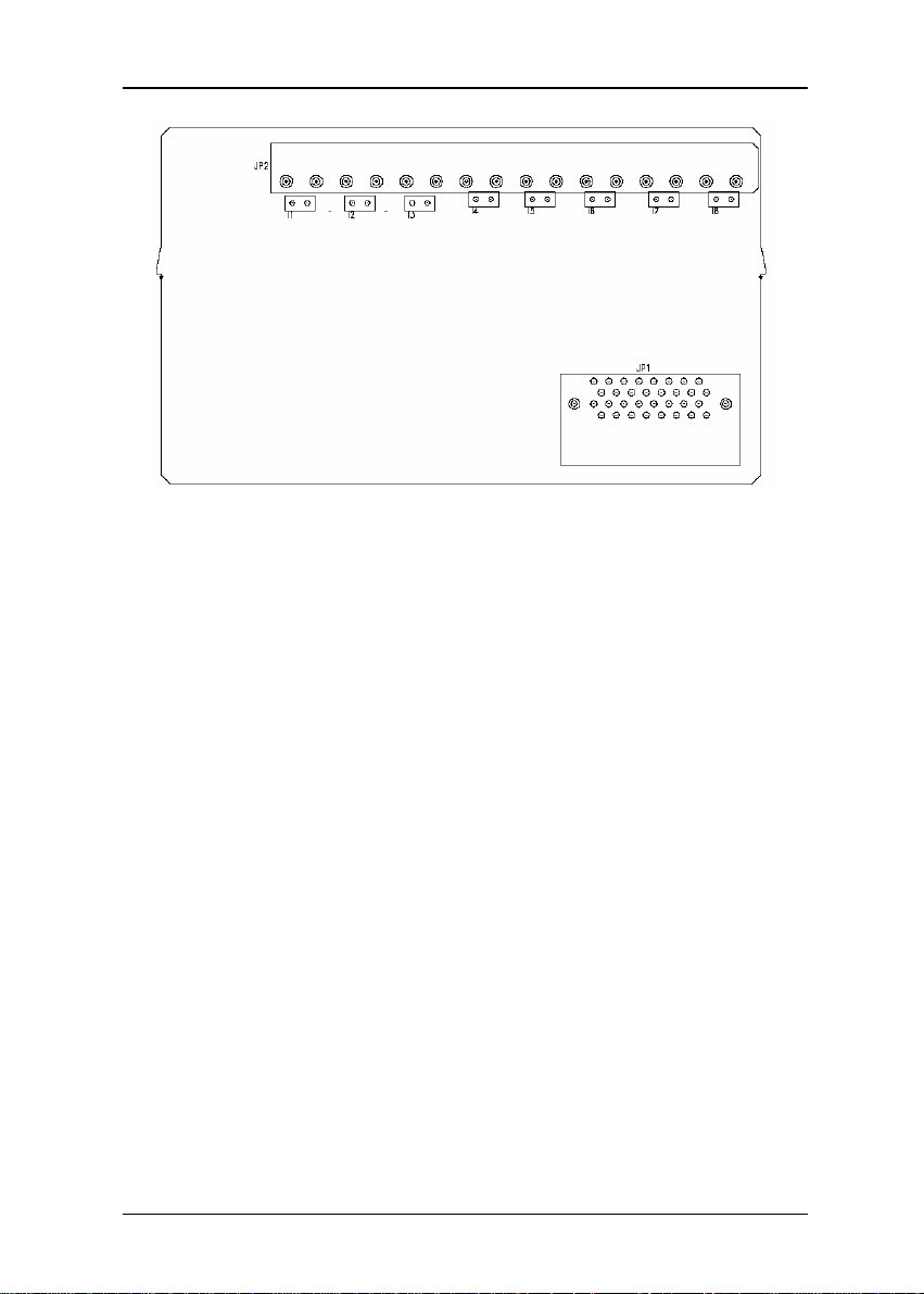
The following figure shows the location of the jumpers:
Figure 5-3 : Jumper locations on the CPU card
Figure 5- 4 : Jumper Settings
5-5
Page 61

Serial Communication Module
LED Status of the ADAM-5090 Module
There are two LEDs for each port on the front panel of the ADAM-5090
to display specific communication status:
a. Green LED (RX): Data Receiving Status; the LED indicator is on when
the port is receiving data.
b. Orange LED (TX): Data Transmitting Status; the LED indicator is on
when the port is transmitting data.
Configure Y our ADAM-5090 Module
This section explains how to config ure an ADAM -5090 m odule be fore
implementing it into your application.
Quick Start
Step 1: Get your host PC ready, and run the ADAM-5510 Utility
Software.
Step 2: Install the ADAM-5090 Module and power on your ADAM-
5510 main unit.
Step 3: Download the executable program to the main unit
Step 4: Monitor the ADAM-5090 Module’s current status from the PC
through the utility software.
A basic example program for the ADAM-5090
main ()
{
//Install the port you would like to use. Here we install slot 0,
port 1.
port_install(1);
// Here we install slot 2, port 2.
port_install(22);
//Select working port. Here we select slot 0, port 1.
port_select(1);
//Set port data format.
//Here we set the data format of port 1 as lengh:8; parity:0;stop_bit:1.
(N81)
port_set_format(1,8,0,1);
//Set port speed. Here we set comm unication speed of port 1 as 11520 0
bps.
//(L is necessary)
6
ADAM 5000 IO modules User’s Manual
5-
Page 62

port_set_speed(1,115200L);
//Enable Port FIFO. Here we enable 128 byte FIFO for port1.
port_enable_fifo(1);
//After these above settings are enabled, you can apply any
other function library to implement your program.
}
—A receive-and-transmit example program for the ADAM-5090
main()
{
int err_value, char character port_installed(1)
:
:
port_enable_fifo(1);
//check whether error has been received or not
err_value=port_rx_error(1);
//if error detected, print out the message
if(err_value)
{
printf(“\n Rx Error , The LSR Value=%02X”, Err_value)”;
}
//check whether FIFO receives data or not; if data received, rea d a
character
if(port_rx_ready(1))
{
character=port_rx(1);
}
//check whether FIFO is empty or not, if empty, send a character
if(port_tx_empty(1));
{
port_tx(1, character)
}
}
Chapter 5
5-7
Page 63

Analog I/O Modules Calibration 6
Page 64

Analog I/O Modules Calibration
Analog input/output modules are calibrated when you receive them.
However, calibration is sometimes required. No screwdriver is necessary
because calibration is done in software with calibration parameters stored in the
ADAM-5000 analog I/O module‘s onboard EEPROM.
The ADAM-5000 system comes with the ADAM utility software that
supports calibration of analog input and analog output. Besides the
calibration that is carried out through software, the modules incorporate
automatic Zero Calibration and automatic Span Calibration at boot up or
reset.
6.1 Analog input module calibration
Modules: ADAM-5017, 5017H, 5018
1. Apply powe r to t he A DAM -50 00 system that the analog input
module is plugged into and let it warm up for about 30 minutes
2. Assure that t he module is correctly installed and is p roperly
configured for the input range you want to calibrate. Y ou can do
this by using the ADAM utility software.
3. Use a precision voltage source to apply a span calibration voltage
to the module‘s V0+ and V0- terminals. (See Tables 5-2 and 5-3
for reference voltages for each range.)
Figure 6-1: Applying calibration voltage
4. Execute the Zero Calibration command (also called the Offset
Calibration command).
2
ADAM 5000 IO modules User’s Manual
6-
Page 65

Figure 6- 2 : Zero calibratio n
5 . Execute the Span Calibration command. This can be do ne with the
ADAM utility software.
Chapter 6
Figure 6-3 : Sp an calibration
6-3
Page 66

Analog I/O Modules Calibration
6. CJC Calibration (only for T/C input module)
Figure 6- 4 : Cold junction calibra tion
* Note: Zero calibration and span calibration must be completed
before CJC calibration. To calibrate CJC, the thermocouple
attached to ADAM-5018 and a standard thermometer
should be used to measure a standard known temperature,
such as the freezing point of pure water. The amount of
offset between the ADAM-5018 and the standard
thermometer is then used in the ADAM utility to complete
CJC calibration.
4
ADAM 5000 IO modules User’s Manual
6-
Page 67

Calibration voltage (ADAM-5017/5018)
Module
5018
5017
Input Range Code
(Hex)
00h ±15 mV +15 mV
01h ±50 mV +50 mV
02h ±100 mV +100 mV
03h ±500 mV +500 mV
04h ±1 mV +1 V
05h ±2.5 V +2.5 V
06h ±20 mV +20 mA (1)
0Eh
0Fh
10h
11h
12h
13h
14h
07h Not used
08h
09h ±5 V +5 V
0Ah ±1 V +1 V
0Bh ±500 mV +500 mV
0Ch ±150 mV +150 mV
0Dh ±20 mA +20 mV (1)
Input Range
J thermocouple 0 to
1370°C
K thermocouple 0 to
1370°C
T thermocouple -100 to
400°C
E thermocouple 0 to
1000°C
R thermocouple 500 to
1750°C
S thermocouple 500 to
1800°C
B thermocouple 500 to
1800°C
ºC±10 V
Table 6- 1 : Calibra tion voltage of ADAM-5017/5018
Chapter 6
Span Calibration
Voltage
+50 mV
+50 mV
+22 mV
+80 mV
+22 mV
+22 mV
+152 mV
+10 V
6-5
Page 68

Analog I/O Modules Calibration
Calibration voltage (ADAM-5017H)
Module
5017H
Input Range Code
(Hex)
00h ±10 V +10 V
01h 0 ~ 10 V +10 V
02h ±5 V +5 V
03h 0 ~ 5 V +5 V
04h ±2.5 V +2.5 V
05h 0 ~ 2.5 V +2.5 V
06h ±1 V +1 V
07h 0 ~ 1 V +1 V
08h ±500 mV +500 mV
09h 0 ~ 500 mV +500 mV
0ah 4 ~ 20 mA *(1)
0bh 0 ~ 20 mA *(1)
Input Range Span Calibration Voltage
Note: You can substitute 2 .5 V for 20 mA if you remove the current conversion
resistor for that channel. However, the calibration accuracy will be limited
to 0.1% due to the resistor's tolerance.
Table 6-2 : Calibration voltage of ADAM-5017H
6
ADAM 5000 IO modules User’s Manual
6-
Page 69

6.2 ADAM-5013 RTD Input Resistance Calibration
1 . Apply power to the module and let it warm up for about 30 minutes.
2. Make sure that the module is correctly installed and is properly
con- figured for the input range you want to calibrate. You can
use the ADAM utility software to help in this.
3. Connect the correct reference self resistance between the screw
terminals of the ADAM-5013 as shown in the following wiring
diagram. Table 2 below shows the correct values of the span and
zero calibration resistances to be connected. Reference
resistances used can be from a precision resistance decade box or
from discrete resistors with the values 60, 140, 200 and 440 ohms.
Chapter 6
Figure 6-5 : Applying calibration resistance
4 . First, with the correct zero (offset) calibration resistance connected
as shown above, issue a Zero Cali bration com mand to the m odule
using the Calibrate option in the ADAM utility software.
5. Second, with the correct span resistance connected as shown
above, issue a Span Calibration command to the module using
the Calibrate option in the ADAM utility software. Note that the
module zero calibration must be completed prior to the span
calibration.
Note: If the above procedure is ineffective, the user must first issue an
RTD Self Calibration comm and $aaSi2 to the module and then
complete steps 4 and 5 after self calibration is complete.
6-7
Page 70

Analog I/O Modules Calibration
Calibration resistances (ADAM-5013)
Input
Range
Code (Hex)
Input Range Span
Calibration
Resistance
Zero
Calibration
Resistance
20
21
22
23
24
25
26
27
28 Ni, -80 to 100° C 200 Ohms 60 Ohms
29 Ni, 0 to 100°C 200 Ohms 60 Ohms
Pt, -100 to 100°C A =
0.00385
Pt, 0 to 100°C A =
0.00385
Pt, 0 to 200°C A =
0.00385
Pt, 0 to 600°C A =
0.00385
Pt, -100 to 100°C A =
0.00392
Pt, 0 to 100°C A =
0.00392
Pt, 0 to 200°C A =
0.00392
Pt, 0 to 600°C A =
0.00392
140 Ohms 60 Ohms
140 Ohms 60 Ohms
200 Ohms 60 Ohms
440 Ohms 60 Ohms
140 Ohms 60 Ohms
140 Ohms 60 Ohms
200 Ohms 60 Ohms
440 Ohms 60 Ohms
Table 6 -3: Calibration resistances of ADAM-5013
8
ADAM 5000 IO modules User’s Manual
6-
Page 71

Chapter 6
6.3 Analog output module calibration
The output current of analog output modules can be calibrated by using
a low calibration value and a high calibration value. The analog output
modules can be configured for one of two ranges: 0-20 m A and 4-20 mA.
Since the low limit of the 0-20 mA range (0 mA) is internally an absolute
reference (no power or immeasurably small power), just two levels are
needed for calibration: 4 mA and 20 mA.
1 . Apply power to the ADAM-5000 system including the analog output
module for about 30 minutes.
2. Assure that the module is correctly installed and that its configuration
is according to your specifications and that it matches the output range
you want to calibrate. You can do this by using the ADAM utility
software.
3 . Co nnect either a 5-digit mA m eter or volt met er with a shunt resist or
(250 ohms, .01 % and 10 ppm) to the screw terminals of the module.
Figure 6-6: Output module calibration
6-9
Page 72

Analog I/O Modules Calibration
4. Issue the Analog Data Out command to the module with an
output value of 4 m A.
5. Check the actual output value at the modules terminals. If this
does not equal 4 mA, use the "Trim" option in t he "Calibrate"
submenu to change the actual output. Trim the module until the
mA meter indicates exactly 4 mA, or in case of a voltage meter with
shunt resistor, the meter indicates exactly 1 V. (When calibrating for
20 mA using a voltage meter and shunt resistor, the correct
voltage should be 5 V.)
6. Issue the 4 mA Calibration command to indicate that the ou tput
is calibrated and to store the calibration parameters in the
module's EEPROM.
7. Execute an Analog Da ta Out command with an output value
of 20 mA. The module's output will be approximately 20 mA.
8 . Execute the Trim Calibration command as often as necessary until
the output current is equal to exactly 20 mA.
9. Execute the 20 mA Calibration command to indicate that the
present output is exactly 20 mA. The analog output module
will store its calibrat ion param eters in t he unit's EE PROM.
10
ADAM 5000 IO modules User’s Manual
6-
 Loading...