

Page 1

Part no. 2000455000 2nd Edition Printed in Taiwan October 1997ADAM and the ADAM logo are trademarks of Advantech
ADAM-4550
Radio Modem Module
(RS-232/485 Interface)
User’s Manual
Page 2

Contents
1. Introduction..............................................
1.1 Built-in Intelligence.......................... 3
1.2 Features .......................................... 3
1.3 Specifications.................................. 4
2. Installation ..............................................
2.1 Basic Configuration......................... 5
2.2 Power Supply .................................. 5
2.3 RS-485 Communication Wiring ...... 6
2.4 Software Configuration ................... 6
2.5 Configuring ADAM-4550 ................. 7
2.6 Uploading a New Version
of Firmware .................................... 11
2.7 Using the Diagnostics Functions .... 12
2.8 Antenna Installation ........................ 12
3. Using ADAM-4550...................................
3.1 A Test Sample ................................ 16
3
4. ADAM-4550 Command Set.....................
4.1 Set New Configuration .................... 20
4.2 Read Configuration ......................... 22
4.3 Write Identification .......................... 22
4.4 Read Identification .......................... 23
5
4.5 Set Delimiter Character .................. 23
4.6 Read Delimiter Character ............... 24
4.7 Set Data Gate ................................. 24
4.8 Read Data Gate Status...................26
4.9 Read Firmware Version .................. 26
4.10 Read Module Name ...................... 27
4.11 Uploading ...................................... 27
4.12 Send Data to Remote ................... 28
4.13 Get Error Rate Statistics............... 29
Appendix A: External Antenna Options .....
Appendix B: External Antenna
14
Wiring Diagram.....................
17
30
32
2 ADAM-4550 User's Manual
Page 3

FCC Identification
MKZAZY4550MDM
FCC Warning
This equipment has been tested and found to comply with the limits for a Class A digital device,
pursuant to Part15 of the FCC Rules. These limits are designed to provide reasonable protection
against harmful interference when the equipment is operated in an industrial / commercial installation. This equipment generates, uses, and can radiate radio frequency energy and, if not installed
and used in accordance with the instruction manual, may cause harmful interference to radio communications. Operation of this equipment in a residential area is likely to cause harmful interference in which case the user will be required to correct the interference at his own expense. However, there is not a guarantee that interference will not occur in a particular installation.
ADAM-4550 User's Manual 3
Page 4

1. Introduction
ADAM-4550 is an economical, wireless RS-232/
485 converter designed to interface any bidirectional RS-485 device with a control center host
computer. The ADAM-4550 can be used in data
acquisition where data sensors are inaccessible to the host computer due to wiring difficulties or long distances that make wiring impractical or impossible.
1.2 Features
•Built-in microprocessor
•Data transmission speeds up to 115.2 Kbps
•Built-in RS-485 line surge protection
•Software configurable address and baud rate
•Easily mounted on DIN rails, panels or as a
piggyback unit.
• All communication setup information stored
1.1 Built-in Intelligence
The ADAM-4550 is equipped with an on-board
microprocessor and a radio-frequency (RF)
module that can be used to interface one host
computer with multiple RS-485 networks. Each
RS-485 network can be used to support numerous data acquisition devices.
4 ADAM-4550 User's Manual
on system EEPROM
•Automatically sets RS-232 port to DTE/DCE
and automatic RS-485 data flow control
•Can be used as point to point or point to
points communication
•Can be operated with address or without
address
Page 5

1.3 Specifications
•Transmission speed (bps): 300, 600, 1200,
2400, 4800, 9600, 19.2K, 38.4K, 57.6K,
115.2K (transmission speeds are software
configurable)
• Radio frequency : 2.442 GHz, Direct
Sequence Spread Spectrum (DSSS)
•Radio bandwidth : 22 MHz
•Radio transmission power: 100 mW nom-
inal
•Radio transmission rate: 1 Mbps
•Power requirement: Unregulated (+10V
to +30VDC) with protection from power reversals
•Standard accessories: Nylon DIN-rail
mounting adapter, SECC panel mounting
bracket
• RS-232 interface connector: DB-9
(female)
•RS-485 interface connector: Plug-in screw
type terminal [accepts AWG 1-#12 or 2#14~#22 (0.5 to 2.5 mm2) wires]
•Operating temperature: -10
•Power consumption : 4 W
•Communication distance: 550 ft. effective
DC
range (under open site test with 2 dBi omni
antenna). Actual distance depends on environmental conditions, antenna type and
positioning.
o
to 70o C
• Case: ABS with captive mounting hardware
ADAM-4550 User's Manual 5
Page 6

2. Installation
2.1 Basic Configuration
Before installing the ADAM-4550 in an existing
network, the ADAM-4550 unit should be preconfigured. Though all modules are initially preconfigured at the factory, it is recommended that
you check the baud rate settings.
Factory Default Settings:
Baud Rate: 9600 bps (both RS-232 and RS-485)
Delimiter: {
Address: 00
2.2 Power Supply
For ease of use in industrial environments,
ADAM modules are designed to accept industry
standard +24 VDC unregulated power. Modules
are certified for operation with any power supply source between +10 and +30 VDC. Power
ripples must be limited to 5 V peak to peak, while
voltage must in all cases remain between +10
and +30 VDC. All power supply specifications are
referenced at the module connector.
Power cables should be selected according to
the number of modules connected and the length
of the power lines. When using a network with
long cables, we advise the use of thicker wire to
limit the line voltage drop. In addition to serious
voltage drops, long voltage lines can also cause
interference with communication wires.
We advise that the following standard colors (as
indicated on the modules) be used for power
lines:
+Vs ð (R) Red
GND ð (B) Black
6 ADAM-4550 User's Manual
Page 7

2.3 RS-485 Communication Wiring
We recommend using shielded-pair cables which
comply with the EIA RS-485 standard to reduce
interference in an ADAM network. Only one set
of twisted-pair cables is required to transmit both
DATA and RTS signals. We advise that the following standard colors (as indicated on the modules) be used for the communication lines:
DATA+ ð (Y) Yellow
DATA- ð (G) Green
2.4 Software Configuration
The ADAM-4550 comes with a setup disk that
contains software for the following:
•Baud rate configuration
•Address configuration
Note: 1. Before turning on the power and
configuring the ADAM-4550, make sure it is
connected to your host computer through an
RS-232 cable and that the host computer is
on. The ADAM-4550 will automatically detect
the cable and set itself as a DTE/DCE
according to the RS-232 port of the connected
host computer. If there is no RS-232 cable
connected to the host computer, the ADAM4550 will set itself as a DCE when you turn on
the power.
For RS-485 wireless transceiver applications,
the user can leave the RS-232 port opened.
The ADAM-4550 should set RS-232 as a DCE
after power is turned on.
2. The pin INIT (pin 6) should be grounded while
you turn on the power of ADAM-4550 for configuration. For normal operation, just leave INIT
(pin 6) open while you turn the power on.
•Statistical RF error rate retrieval
•Firmware upload tool for firmware upgrades
ADAM-4550 User's Manual 7
Page 8

2.5 Configuring ADAM-4550
1. Insert the ADAM-4550 disk in drive A. Start
Microsoft Windows. From the Program
Manager, select the File menu and choose
Run. Type a:\ADAM4550 and press EN-
TER. The ADAM Configuration and Diag-
nostics window should now open.
2. You must now set the host computer’s port
configuration before configuring your ADAM-
4550. To configure your host communication port, select the Setting... menu and
choose Local. A dialog box will open. Se-
lect the proper COM port that is connected
to the ADAM-4550 and set the baud rate to
9600. Click the OK button.
3. Connect your PC’s RS-232 serial port to
ADAM-4550’s RS-232 port. Connect the
INIT pin with the ADAM-4550’s ground pin.
Turn on the power. The unit is now in configuration mode. The green LED light should
blink slowly.
4. You must now search your unit for its current settings. To do this, select the Setting...
menu and choose Get. Enter a starting address into the dialog box or use the default
start address 0. Click the OK button. The
configuration software will scan the unit for
the address by matching the unit’s address
with each address number between the starting address and 255. If the unit’s address
is found, its ID address, baud rate and delimiter settings will be displayed.
5. You may now change the settings. To
change the configuration, select the Set-
ting... menu and choose Set. A dialog box
will open. Enter the new configuration settings (new address, identification, new baud
rate, master/slave) and click the OK button.
Follow the procedure in the Search section
to get the new desired configurations.
8 ADAM-4550 User's Manual
Page 9
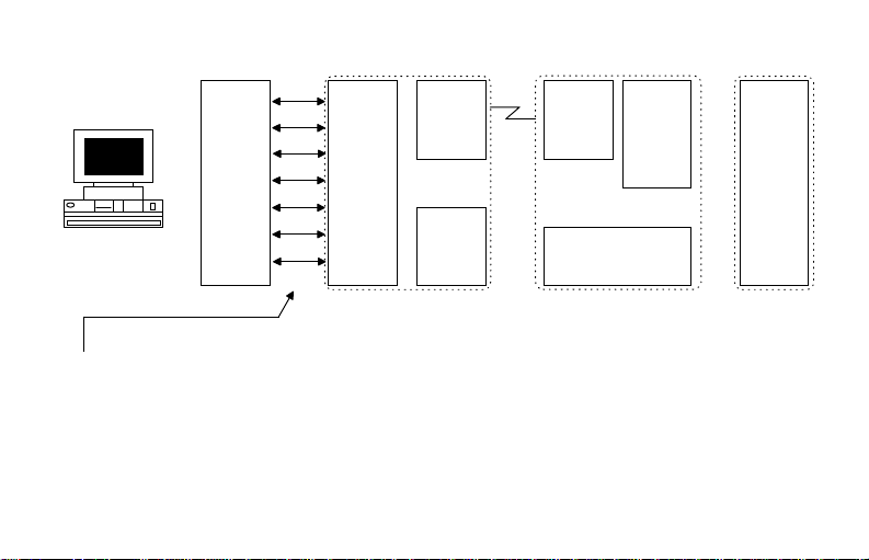
2 RX
3 TX
PC
Note:
The RS-232 cable does not have to be
7 RTS
8 CTS
4 DTR
6 DSR
5 GND
RS-232 ADAM-4550 ADAM-4550 ADAM-4011
2 RX/TX
3 TX/RX
7 CTS/RTS
8 TRS/CTS
4 DSR/DTR
6 DTR/DSR
5 GND
RF
Module
DATA+
DATA-
RS-485
RF
Module
RS-232 Connector
DATA+
DATA-
RS-485
DATA+
DATA-
RS-485
a null-modem cable. The ADAM-4550
will automatically detect and set itself
as a DCE.
Figure 1: Basic Connection Diagram
ADAM-4550 User's Manual 9
Page 10
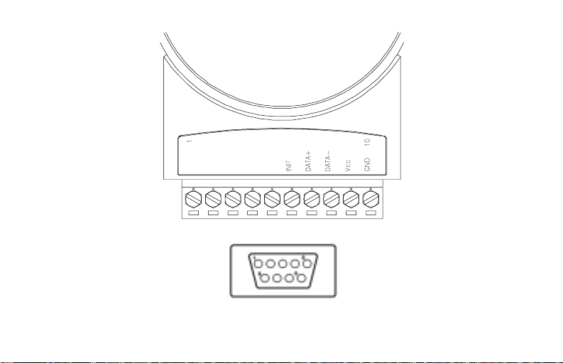
Figure 2: Pin Assignment
10 ADAM-4550 User's Manual
Page 11

Note: 1. The address between F8h and FFh
are used for non-addressable modules.
The addresses for addressable modules
are between 00h and F7h.
2. The ADAM-4550 can be configured
as either a MASTER type module or a
SLAVE type module. The MASTER
ADAM-4550 is the module connected to
the host PC. The SLAVE ADAM-4550s
are those connected to remote RS-485
devices or other ADAM series products.
Run your configuration program
ADAM4550.EXE to set the unit to the
correct type.
6. Disconnect INIT pin from the ground pin after configuration is complete.
Note: During the Get or Set configuration pro-
cess, the configuration software will automatically search the unit for current
settings using a certain default ID ad-
dress. If the unit does not respond, a
scanning address dialog box will appear.
Click OK in the box to start the scanning process. Now the configuration
software will scan for ID addresses between 0 and 255. The current settings
of the unit will be displayed when the
units address is found. Users can also
change the time-out value in the scanning dialog box to allow more scanning
time for the configuration software.
2.6 Uploading a New Version of Firmware
1. Follow the procedures in sections A.1 and
A.2 and start the Adam Configuration and
Diagnostic Program.
2. Select the Setting... menu and choose Lo-
cal. A dialog box will open. Select the
proper COM port connected to the ADAM4550 and set the baud rate to 9600. Click
the OK button.
ADAM-4550 User's Manual 11
Page 12

3. Select the Upload menu. A dialog box will
open. Enter the file name where the firmware to be uploaded is located. Click the
OK button to begin uploading. The green
LED light on ADAM-4550 now changes to a
steady glow. When uploading is completed, the green LED will turn off. Turn off your
ADAM-4550’s power and then turn the power
on again to complete the uploading process.
The ADAM-4550 unit is now ready to be
configured. Follow procedures in section A
to re-configure the unit.
2.7 Using the Diagnostics Functions
Start the ADAM Configuration and Diagnostic
Program. Select the Diagnostics menu. A dialog box will open. Enter the selected ADAM4550 unit ID address and the communication
port baud rate. Click the OK button. The RF
link quality indicator will be displayed:
Total Received Packets indicates the total num-
ber of packets received by the selected ADAM4550 unit.
CRC Error indicates the number of received
packets with the CRC checking error.
Check Sum indicates the number of received
packets with the Check Sum error.
Transmit acknowledged indicates the total
number of acknowledged packets received by
the selected ADAM-4550 unit from the remote
ADAM-4550 unit.
Transmit retransmitted indicates the total number of retransmitted packets sent out from the
selected ADAM-4550 unit due to poor link quality (i.e. no acknowledgment received).
12 ADAM-4550 User's Manual
Page 13

2.8 Antenna Installation
Indoor communication distance is about 300 to
550 ft. using a standard 2 dB antenna. However, actual distance depends on environmental
conditions as well as antenna type and positioning.
Longer communication distances can be
achieved by using an antenna with a higher gain.
A table of communication ranges as a function
of differing combinations of antennas (at the
source and receiving ends) is displayed below.
Note : 1. While using directional antennas, care
should be taken to install and adjust the antennas direction according to the instructions of
the antenna’s manufacturer. Please see the
example specification for an external 24 dBi antenna at appendix A.
2. A user’s license may be required to use a
directional antenna. Please consult your local
authority for local regulations.
3. We strongly recommend that you install
ADAM-4550 as near as possible to its antenna.
Where the antenna has to be located at a dis-
annetnA
taniaG
dnerehtie
Bd42
lanoitcerid
Bd81
lanoitcerid
-inmoBd11
lanoitcerid
Bd42
mK01mK5mK2
mK5mK5.2mK1
mK2mK1mK5.0
Bd81
lanoitcerid
lanoitcerid
tance from the ADAM, special RF cable is re-
-inmoBd11
lanoitcerid
quired. Please see the example cable connection arrangement in appendix B.
4. Omnidirectional antennas should be used
when the ADAM-4550 communicates with more
than one other ADAM-4550 unit located in different directions.
ADAM-4550 User's Manual 13
Page 14

3. Using ADAM-4550
Connect one ADAM-4550 to the controlling PC’s
serial port with the RS-232 cable. Connect remote ADAM-4550 units to remote data units
through the RS-485 bus.
Configure each ADAM-4550 unit by following the
procedures in section A.
Start the ADAM Configuration and Diagnostic
Program on the controller PC. Select the Set-
ting... menu and choose Local. In the dialog
box, select the proper COM port and set the baud
rate to the one configured for the ADAM-4550.
Make sure all ADAM-4550 units are powered
off. From the ADAM Configuration and Diagnostic Program, select the Connections menu
and choose Connect. Turn on power to the
ADAM-4550 connected to the controlling PC and
the green LED should blink slowly. Turn on the
power to the remote ADAM-4550 units one by
one. The green LED on the ADAM-4550 that is
connected to the controlling PC, as well as the
green LEDs on the remote ADAM-4550 units
should now be in a rapid blinking mode. This
indicates that the RF links between the controlling unit and all the remote units have been established.
Note: It is important that during the initial set-
up, the ADAM-4550 unit connected to
the controlling PC must be powered up
before the other remote ADAM-4550
units are powered up. Moreover, any
devices connected to an ADAM-4550
through RS-232 must be powered on before the ADAM-4550 is powered on.
This will allow the ADAM-4550 to automatically detect the connected device
and set itself into proper DCE or DTE
modes.
14 ADAM-4550 User's Manual
Page 15

aa
PC
RS-232
Type { aaDDD....(cr)
MASTER
ADAM-4550
115.2
kbps
ADAM-4550-S
SLAVE
ADAM-4550
ADAM-4550-00
SLAVE
ADAM-4550
AA
ADAM-4550-01
RS-485 DEVICES
115.2 kbps
RS-485 DEVICES
115.2 kbps
Type { AADDD....(cr)
Figure 3: Test Sample
ADAM-4550 User's Manual 15
Page 16

3.1 A Test Sample
1. Follow procedures in section C to install one
ADAM-4550 unit as the MASTER module
for a controlling PC and two ADAM-4550s
as SLAVEs for the remote devices (see Fig.
3).
2. Start the ADAM Configuration and Diagnostic Program on the controlling PC. Select
Generate-Traffic menu and choose Send
One Packet. In the window area type in
{AADDD...... (cr)} where { is the delimiter
selected when configuring the ADAM-4550
units, AA is the hexadecimal unit ID address
and DDD...... is the data. The transmitted
data DDD...... should be displayed on the
PC monitor connected to the remote
ADAM-4550.
16 ADAM-4550 User's Manual
Page 17

4. ADAM-4550 Command Set
In order to avoid communication conflicts, all
actions are instigated by the host computer when
several devices attempt to send data at the same
time . The basic form is a command/response
protocol with the host initiating the sequence.
The host issues a command to a module with a
specified address and waits a specific amount
of time for the module to respond. If no response is received, a time-out command aborts
the sequence and returns control to the host.
Syntax
[delimiter character] [address] [command] [data]
[carriage return]
Every command begins with a delimiter character. Most of the commands can use a $ (dollar
sign) or a % (percentage sign), but the
mode
command uses one of eight special char-
acters. The delimiter character is followed by a
Data Pass
two-character address (hexadecimal) that specifies the target module. Depending on the command, an optional data string follows the command string. Every command is terminated by
a (cr) carriage return. Command sets are divided into two categories: configuration mode
commands and data pass mode commands:
ADAM-4550 User's Manual 17
Page 18

Configuration Mode Commands
xatnySdnammoCemaNdnammoCnoitpircseD
)rc(PPFFCCTTNNAA%noitarugifnocwensteS AAeludomtaetarduab,sserddawentesotstseuqeR
)rc(2AA$noitarugifnocsdaeR AAsserddaeludommorfnoitarugifnoctnerructegotstseuqeR
)rc()gnirtsDI(6AA$noitacifitnedisetirW AAsserddataeludomot)setyb61ot0(atadnoitacifitnediehtsteS
)rc(7AA$noitacifitnedisdaeR AAsserddataeludomehtmorfatadnoitacifitnediehtsdaeR
)rc(DCAA$retimiledehtsteS ataDrof)"|","~","}","{","^","]","[",":"(retcarahcretimiledehtsteS
)rc(DAA$retimiledehtsdaeR AAsserddataeludomehtmorfretcarahcretimiledsdaeR
)rc(FAA$noisreverawmrifsdaeRrebmunnoisreverawmrifehtsdaeR
)rc(MAA$emaneludomsdaeReludomehtfoemanledomehtsdaeR
)rc(LAA$gnidaolpustratS AAsserddataeludomehtoterawmrifwenfognidaolpustratS
)rc(2D1DAAA&etaGataDsteS
)rc(BAA&sutatSetaGataDsdaeR sutatsetaGataDnruterotAAsserddataeludomehtstseuqeR
dnammoc
)0(esolC
sdnammocedomssaP
ro)1(nepOotetaGataDtesotAAsserddataeludomehtstseuqeR
18 ADAM-4550 User's Manual
Page 19

Data Pass Mode Commands
xatnySdnammoCxatnySdnammoC
xatnySdnammoCxatnySdnammoCemaNdnammoCemaNdnammoC
xatnySdnammoC
)rc(DDAA{etomerotatadsdneS AAsserddataeludometomerehthguorhtDDgnirtsatadsdneS
)rc(QAA&scitsitatsetarrorresteG AAsserddataeludomehtmorfscitsitatsetarrorreFRsteG
)rc(2D1DAAA&etaGataDsteS
)rc(BAA&sutatSetaGataDsdaeR sutatsetaGataDnruterotAAsserddataeludomehtstseuqeR
emaNdnammoCemaNdnammoCnoitpircseDnoitpircseD
emaNdnammoC
dnammoc
)0(esolC
noitpircseDnoitpircseD
noitpircseD
ro)1(nepOotetaGataDtesotAAsserddataeludomehtstseuqeR
Note: All commands should be issued in upper case letters.
ADAM-4550 User's Manual 19
Page 20

Command Descriptions
4.1 Set New Configuration
Description Requests to set new baud rate,
new address… for module.
Syntax %AANNTTCCFFPP(cr)
AA: module address ( 2 characters hexadecimal )
NN: new module address
TT: set to 0x40(H)
CC: High 4 bits represents RS-
232 baud rate code for module.
Low 4 bits represents RS-485
baud rate code for module.
Currently, RS-232 and RS-485
ports have the same baud rate.
Baud rate code are listed below:
7 6 5 4 3 2 1 0
RS-232 RS-485
Code Baud rate
01 300 bps
02 600 bps
03 1200 bps
04 2400 bps
05 4800 bps
06 9600 bps
07 19200 bps
08 38400 bps
09 57600 bps
0A 115200 bps
20 ADAM-4550 User's Manual
Page 21

FF : ADAM-4550 mode configuration
Response !AA(cr) if the command is valid
?AA(cr) if an invalid command is
entered
Example Command:
PP: RS-232/RS-485 data format. It is currently
a fixed number.
%0A1B40AA2103(cr)
Response: !0A(cr)
The ADAM-4550 module with
address 0Ah is configured to a
new address 1Bh and the baud
rate is set to 115.2 Kbps.
RS-232 data format is fixed to N,
8, 1.
ADAM-4550 User's Manual 21
Page 22

4.2 Read Configuration
Description Requests to read the current
baud rate and address from the
module.
Syntax $AA2(cr)
AA: module address ( 2 hexadecimal characters )
Response !AATTCCFFPP(cr) if the com-
mand is valid (refer to “Set New
Configuration” in Command Set)
?AA(cr) if an invalid command is
entered
Example Command : $0A2(cr)
Response:
!0A40AA2103(cr)
4.3 Write Identification
Description Requests to assign identification
data to the module at address
AA. The identification character
lengths can range from 0 to 16
bytes including carriage-return.
Syntax $AA6(identification
characters)(cr)
Response !AA(cr) if the command is valid
?AA(cr) if an invalid command is
entered
Example Command:
$0A6ADAM4550 Unit#1(cr)
Response: !0A(cr)
22 ADAM-4550 User's Manual
Page 23

4.4 Read Identification
Description Requests to read identification
data from the module at address
AA.
Syntax $AA7(cr)
Response !AA(identification characters)(cr)
if the command is valid
?AA(cr) if an invalid command
is entered
Example Command: $0A7(cr)
Response: !0AADAM4550
Unit#1(cr)
4.5. Set Delimiter Character
Description Requests to assign a new delim-
iter character to the module at
address AA.
Syntax $AACD(cr)
D: delimiter character selected
from ‘:’,‘[‘, ‘]’,‘^’, ‘{‘, ‘}’, ‘|’, ‘~’
Response !AA(cr) if the command is valid
?AA(cr) if an invalid command
is entered
Example Command: $0AC[(cr)
Response: !0A(cr)
ADAM-4550 User's Manual 23
Page 24

4.6. Read Delimiter Character
Description Requests to read the delimiter
character data from the module
at address AA.
Syntax $AAD(cr)
Response !AA(delimiter character)(cr) if the
command is valid
?AA(cr) if an invalid command
is entered
Example Command: $0AD(cr)
Response: !0A[(cr)
4.7. Set Data Gate
Description Requests the module at address
AA to set data gate to open(1) or
close (0).
Syntax &AAAD1D2(cr)
where AA is the module address
D1 = 1 Open data gate
D1 = 0 Close data gate
D2 = 1 Write to Flash memory
D2 = 0 Do not write to Flash
memory
Response !AA(cr) if the command is valid
?AA(cr) if an invalid command is
entered
Example Command: &0AA00(cr)
24 ADAM-4550 User's Manual
Page 25

Response: !0A(cr)
The command asks the module
at address 0Ah to close the data
gate and not to write to FLASH
memory.
Command: &0AA11(cr)
Response: !0A(cr)
The command requests the
module at address 0Ah to open
the data gate and write to Flash
memory.
Note: 1. If the command asks the module to
write to FLASH memory, the status will
remain at Open Gate/Write to FLASH
when the power is turned off and then
on again.
2. If the command asks the addressable
module to open the data gate, the module will automatically assume non-addressable mode. This enables the module to issue commands without adding
{AA until the user issues another command to close the data gate.}
ADAM-4550 User's Manual 25
Page 26

4.8. Read Data Gate Status
Description Requests the module at address
AA to return data gate status.
Syntax &AAB(cr)
Response !AAS(cr) if the command is val-
id where
S = 1 open data gate
S = 0 close data gate
?AA(cr) if an invalid command is
entered
Example Command: &0AB(cr)
Response: !0A0(cr)
The module returns that current
data gate status is close.
4.9. Read Firmware Version
Description Requests to read the ADAM-
4550 firmware version number
from the module at address AA.
Syntax $AAF(cr)
Response !AA(version number)(cr) if the
command is valid
?AA(cr) if an invalid command is
entered
Example Command: $0AF(cr)
Response: !0AA1.0(cr)
26 ADAM-4550 User's Manual
Page 27

4.10. Read Module Name
Description Requests to read the module
name from the module at address AA.
Syntax $AAM(cr)
Response !AA(module name)(cr) if the
command is valid
?AA(cr) if an invalid command
is entered
Example Command: $0AM(cr)
Response: !0A4550(cr)
4.11. Uploading
Description Requests to upload new firm-
ware to the module at address
AA.
Syntax $AAL(cr)
Response !AA(cr) if the command is valid
?AA(cr) if an invalid command
is entered
After having received ‘!AA(cr)’
response, the host computer
starts to send 2 bytes Hi-Lo data
length followed by the firmware
binary data. If the host receives
response ‘?AA(cr)’ or no re-
sponse, it will stop sending the
binary data.
ADAM-4550 User's Manual 27
Page 28

Example Command : $0AL(cr)
Response : !0A(cr)
command : 0A 80 12 34 56
..................... length 2688
bytes followed by data 12h 34h
4.12. Send Data to Remote
Description Send the DATA to RS-485 de-
vice through the remote module
at address AA
This command only works in
Data Pass
use the “Set Data Gate” command to open the data gate of
the module at AA so that you
mode. The user can
Syntax {AA(Data string)(cr)
Example Command :
can send the data to module AA
without {AA.
{ — one of the eight optional de-
limiters which is configured into
the module
{0C123456abcdABCD(cr)
The command sends data
‘123456abcdABCD(cr)’ through
the local ADAM4550 and the re-
mote ADAM-4550 module at ad-
dress 0Ch to a connected RS-
485 device.
28 ADAM-4550 User's Manual
Page 29

4.13. Get Error Rate Statistics
Description Requests to get the current RF
Syntax &AAQ(cr)
Response !AAQ(statistic data)(cr) if the
error rate statistics from the
module at address AA.
This command only works in
Data Pass
command is valid
?AA(cr) if an invalid command
is entered
The statistic data format is in the
following order:
Total number of packets: 4
bytes
Total number of CRC error pack-
ets received: 2 bytes
mode.
Note: All data in Hi-Lo format
Example Command : &0AQ(cr)
Total number of checksum error
packets received : 2 bytes
Total number of good packets
received: 4 bytes
Total number of transmit ac-
knowledged packets: 4 bytes
Total number of transmit re-
transmitted packets: 4 bytes
Response : !0AQ0A 00 00 00
01 00 00 00 09 00 00 00
1A 00 00 00 05 00 00 00(cr)
The underlined portion of the
above response is used to show
binary data. In this example:
there are 10 packets received, 1
of them is the CRC error, no
ADAM-4550 User's Manual 29
Page 30

checksum error and 9 good
packets. There are 26 packets
that were transmitted from this
module that received acknowledgment. There are 5 retransmitted packets due since no acknowledgment was received.
Appendix A: External Antenna Options
8 dBi Omni-Directional Antenna
Electrical Specifications:
Frequency: 2.4 to 2.483 GHz
Gain: 8 dBi
3 dB beamwidth: 15° in elevation plane, uni-
form in azimuth plane.
VSWR: 1.5:1 max @ 50 ohm
Polarization: Vertical
Mechanical Specifications:
Antenna Type: Colinear
Size: 750 mm
Weight: 1.5 kg
Connector: Type N Female
Environmental Specifications:
Windload: 240 km/hr.
Humidity: 100%
30 ADAM-4550 User's Manual
Page 31

11 dBi Omni-Directional Antenna
Electrical Specifications:
Frequency: 2.4 to 2.483 GHz
Gain: 11 dBi
3 dB beamwidth: 9° in elevation plane, uni-
form in azimuth plane.
VSWR: 1.5:1 max @ 50 ohm
Polarization: RHCP
Mechanical Specifications:
Antenna Type: Colinear
Size: 1500 mm
Weight: 0.9 kg
Connector: Type N Female
Environmental Specifications:
Windload: 200 km/hr.
Humidity: 100%
24 dBi Grid Parabolic Reflector Directional
Antenna
Electrical Specifications:
Frequency: 2.4 to 2.483 GHz
Gain: 24 dBi
3 dB beamwidth: 10°
Sidelobe level: -20 dB
Front-to-back ratio: 28 dB minimum
VSWR: 1.5:1 max @ 50 ohm
Polarization: Vertical/Horizontal Linear
Cross Polarization: 28 dB minimum
Mechanical Specifications:
Antenna Type: Wire Grid Parabola Reflector
Size: 686 x 813 mm
Weight: 2.4 kg
Connector: Type N Male
Environmental Specifications:
Temperature: -40 to +80° C
Humidity: 100%
ADAM-4550 User's Manual 31
Page 32

Appendix B: External Antenna Wiring Diagram
To Antenna
20' RF Cable Type N
Male to Type N Male
Or
ADAM-4550
3' RF Cable
adapter
20' RF Cable Type N
Female to Type N Male
20' RF Cable Type N
Female to Type N Male
Lightning Arrester
* Not for applications in the U.S. or EC countries.
32 ADAM-4550 User's Manual
 Loading...