

Page 1

February 2001
61202156L1-1B
TDU 120e
User Man u al
Part Numbers
1202156L1
1202155L1
Page 2

Trademarks:
Windows is a registered trademark of Microsoft Corp.
T- Watch is a trademark of ADTRAN, Inc.
OpenView
R
901 Explorer Boulevard
P.O. Box 140000
Huntsville, AL 35814-4000
Phone: (256) 963-8000
© 2001 ADTRAN, Inc.
All rights reserved.
Printed in USA.
Page 3
The following conventions are used in this manual.
Notes provide additional useful information.
Cautions signify information that could prevent service interruption.
Warnings provide information that could prevent damage to
the equipment or endangerment to human life.
Important Safety Instructions
When using your telephone equipment, please follow these basic safety precautions to reduce the risk of fire, electrical shock, or personal injury:
1. Do not use this product near water, such as near a bathtub, wash bowl,
kitchen sink, laundry tub, in a wet basement, or near a swimming pool.
2. Avoid using a telephone (other than a cordless-type) during an electrical
storm. There is a remote risk of shock from lightning.
3. Do not use the telephone to report a gas leak in the vicinity of the leak.
4. Use only the power cord, power supply, and/or batteries indicated in the
manual. Do not dispose of batteries in a fire. They may explode. Check with
local codes for special disposal instructions.
Save These Important Safety Instructions
iii
Page 4

FCC regulations require that the following information be provided to the customer in this manual.
1. This equipment complies with Part 68 of the FCC rules. The required label is
attached to the bottom of the chassis.
2. An FCC compliant telephone cord and modular plug is provided with this
equipment. This equipment is designed to be connected to the telephone network or premises wiring using a c ompatible modular jack which is Part 68
compliant. See installation instructions for details.
3. If your TDU 120e causes harm to the telephone network, the Telephone Company may discont inu e your service temporarily. If possible, they will notify
you in advance. If advance notice is not practical, you will be notified as soon
as possible. You will be advised of your right to file a complaint with the FCC.
4. Your telephone comp any may make change s in its facilities, equi pment, operations, or procedures that could affect the proper operation of your equipment. If they do , you w ill be given advance not ice so as to give you an
opportunity to maintain uninterrupted service.
5. If you experience trouble with the equipment TDU 120e, please contact ADTRAN at (256) 963-8000 for repair/warrant y in formation. The telephone company may ask you to disconnect this equipment from the network until the
problem has been corrected, or until you are sure the equipment is not malfunctioning.
6. This unit c on tains no user serviceabl e parts.
7. The following information may be required when app lying to your local telephone compa ny for leased line facilities .
Service Type REN/SOC FIC USOC
1.544 Mbps -SF 6.0N 04DU9-BN RJ-48C
1.544 Mbps - SF and B8ZS 6.0N 04DU9-DN RJ-48C
1.544 Mbps - ESF 6.0N 04DU9-1KN RJ-48C
1.544 Mbps - ESF and B8Z S 6.0N 04DU9-1SN RJ-48C
8. The FCC recommends that the AC outle t t o which e qui pment r equir in g AC
power is to be in st alle d is provided with an AC surge ar rester.
iv
Page 5

Affidavit Requirements for Connection to Digital Services
• An affidavit is required to be given to the telephone company whenever
digital terminal equip ment without encoded analog content and billing protection is used to transmit digital signals containing encoded analog content
which are intended for eventual convers ion into voice band analog signal
and transmitted on the network.
• The affidavit shall affirm that either no encoded analog content or billing
information is be ing transmitted or that the output of the device meets Part
68 encoded analog conte nt or billing protection spe c ificat ion .
• End use/cus tomer will be responsibl e to file a n affidavit with the local
exchange carrier when connecting unprotected CPE to a 1.544 Mbps or subrate digital servic e .
• Until such time as subrate digital termin al equipment is registered for voice
applications, the affidavit requirements for subrate services are waived.
v
Page 6

Affidavit for Connection of Customer Premises Equipment to 1.544 MBPS
and/or Subrate Dig i tal Se rvices
For the work to be performed in the certified territory of ______________ (telco
name)
State of ________________________________
County of ______________________________
I, _______________________ (name), ____________________ (business address),
_____________________ (telephone number) being duly sworn, state:
I have the responsibility for the operation and maintenance of the terminal equipment to be connected to 1.544 Mbps and/or __________________ subrate digital
services. The terminal equipment to be connected complies with Part 68 of the
FCC rules except for the encode d analog conten t a nd b illing protection specifi c ation. With respect to encoded analo g co nten t and billing protectio n:
( ) I attest that all operations asso ci ated with the e stablishment, maintenance and
adjustment of the digital CPE with respect to encoded analog content and billing
protection information continuously complies with Part 68 of the FCC rules and
Regulations.
( ) The digi tal CPE does not transmit digita l signal s co nta ining encod e d analog
content or billing informati on whic h is i n ten ded to b e decod ed wi thin the t elecomm u ni ca tions n e t work.
( ) The encoded analog content and billing protection is factory set and is not
under the control of the customer.
I attest that the operator(s) maintainer(s) of the digital CPE responsible for the
establishment, maintenance and adjustment of the encoded analog content and
billing information has (have) been trained to perform these functions by successfully having complet e d one o f th e f ollowing (check appropriate blocks):
( ) A. A training course provid ed by the m anu fa cturer/gran te e of the equi p ment
used to encode analog signals; or
( ) B. A training course provided by the customer or authorized representative,
using training materials and instructions provided by the manufacturer/grantee
of the equipment used to encode analog signals; or
( ) C. An independent tr aining course (e.g., tra de school or technical institution)
vi
Page 7

recognized by the manufacturer/grantee of the equipment used to encode analog signals; or
( ) D. In lieu of the proceeding training requirements, the operator(s)/maintainer(S) is (are) under the control of a supervisor trained in accordance with
_______________ (circle one) above.
I agree to provide ____________________ (telco’s name) with proper documentation to demonstrate compliance with the information in the preceding paragraph, if so requested.
_____________________ Signature
_____________________ Title
_____________________ Date
Subscribed and sworn to before me
This _________ day of ___________________, 20__
_______________________________________
Notary Public
My commission expires: _________________________
vii
Page 8

Federal Communications Commission Radio Frequency
Interference Statement
This equipment has been tested and found to comply with the limits for a Class A
digital device, pursuant to Part 15 of the FCC Rules. These limits are designed to
provide reasonable protection against harmful interference when the equipment
is operated in a commercial environment. This equipment generates, uses, an d
can radiate radio frequency energy and, if not installed and used in accordance
with the instruction manual, may cause harmful interference to radio frequencies.
Operation of this equipment in a resident ia l area is li kely t o c ause harm ful i nte rference in which c a se the us e r will be requ ired to correct the interference at his
own expense.
Shielded cable s must be used with t his u nit to ensure compliance wi th Clas s A
FCC limits.
Change or modifications to this unit not expressly approved by the party respons ible fo r complia nce cou ld void the u ser’s auth ority to operat e
the equipment.
Canadian Emissions Requ irements
This digital apparatus does not exceed the Class A l imits for radio noise emiss ions
from digital apparatus as set out in the interference-causing equipment standard
entitled “Digital Apparatus," ICES-003 of the Department of Communications.
Cet appareil nu erique respecte les limites de bru its r a dio ele ctri qu es a pp lic abl es
aux appareils numeriques de Class A prescrites dans la norme sur le materiel
brouilleur: "Appareils Numeriques," NMB-003 edictee par le ministre des Communications.
viii
Page 9

Canad i an Equipment Limitations
Notice: The Canadian Industry and Science Canada label identifies cert ified
equipment. This certification means that the equipment meets certain telecommunicati ons network protective, operational, and safety requir e ments. The
Depa rt ment doe s not g u a ra ntee th e eq u i pment w ill operate to the u s er’s sat i s faction.
Before installing this e quipment, us e rs should ensure that it is permissible to be
connected to the facilities of the local telecommunications company. The equipment must al so be inst alle d usin g an acceptab le me thod s of conn ect ion . In some
cases, the company’s inside wiring associated with a single line individual service may be extended by means of a certified connector assembly (telephone
extension cord). The customer should be aware that compliance with the above
limitations may not prevent de gradation of service in some situ a tions.
Repairs to certified equipment should be made by an authorized Canadian
maintenance facility designated by the supplier . Any repairs or alterations made
by the user to this equipment, or equipment malfunctions, may give the telecomm un ications company cau s e t o re qu e s t the u s er to disconn e ct t he equ i pment.
Users should ensure for their own protection that the electrical ground connections of the power utility, telephon e lines and internal metallic water pipe system, if present, are connected together. This precaution may be particularly
important in rura l areas.
Users should not attempt to make such connections themselves,
but should contract t he appropriate electric inspection authority, or an electrician, as appropriate.
The Load Number (LN) assigned to each terminal device denotes the percentage of the total load to be connected to a telephone loop which is used by the
device, to prevent o ver loa ding. T he te rmination on a loop may con sist o f an y
combination of devices subject only to the requirement that the total of the Load
Numbers of all devices does not exceed 100.
ix
Page 10

Limited Prod uct War ranty
ADTRAN warrants that for five (5) years from the date of shipment to Customer,
all products manufactured by ADTRAN will be free from defects in materials and
workmanship. ADTRAN also warrants that products will conform to the applicable specifications and drawings for such products, as contained in the Product
Manual or in ADTRAN's internal specifications and drawings for such products
(which may or may not be reflected in the Product Manual). This warranty only
applies if Cus tomer giv es ADTR AN writ ten noti ce of d efe cts du ri ng the war ra nty
period. Upon such notice, ADTRAN will, at its option, either repair or replace the
defective item. If ADTRAN is unable, in a reasonable time, to repair or replace
any equipment to a condition as warranted, Customer is entitled to a full refund
of the purchase price upon return of the equipment to ADTRAN. This warranty
applies only to the origina l purchaser an d is not transfer abl e with out ADTRAN's
express written permission. T his w a rr anty becom e s null and void if Custom e r
modifies or alters the equipment in any way, other than as specifically authorized
by ADTRAN.
EXCEPT FOR THE LIMITED WARRANTY DESCRIBED ABOVE, THE FOREGOING CONSTITUTES THE SOLE AND EXCLUSIVE REMEDY OF THE CUSTOMER AND THE EXCLUSIVE LIABILITY OF ADTRAN AND IS I N LIEU OF
ANY AND ALL OTHER WARRANTIES (EXPRESSED OR IMPLIED). ADTR AN
SPECIFICALLY DISCLAIMS ALL OTHER WARRANTIES, INCLUDING (W ITH OUT LIMITATION), ALL WARRANTIES OF MERCHANTABILITY AND FITNESS FOR A PAR T ICULAR PURPOSE. SOME STATES DO NOT ALLOW THE
EXCLUSION OF IMPLIED WARRANTIES, SO THIS EXCLUSION MAY NOT
APPLY TO CUSTOMER.
In no event will ADTRAN or its suppliers be liable to Customer for any incidental, special, punitive, exemplary or consequential damages experienced by either
Customer or a third party (including, but not limited to, loss of data or information, loss of profits, or loss of use). ADTRAN is not liable for damages for any
cause whatsoever (whether based in contract, tort, or otherwise) in excess of the
amount paid for the item. So m e states do no t allo w the lim ita tion or exclu sion of
liability for incidental or consequential damages, so the above limitation or exclusion may not apply to Customer.
x
Page 11

Customer Service, Product Support Information , and Tra ining
ADTRAN will replace or repair this product w ithin fiv e yea r s from the d ate of
shipment if the product does not meet its published specification, or if it fails
while in serv ice.
A return material authorizatio n (RMA) is req uired prior to returning equipment
to ADTRAN. For service, RMA requests, training, or more information, see the
toll-free contact numbers given below.
Presales Inquiries an d Applications Support
Please contact your local distributor, ADTRAN Applications Engineering, or
ADTRAN Sales:
Applications Engineering (800) 615-1176
Sales (800) 827-0807
Post-Sale Support
Please contact your local distributor first. If your local distributor cannot help,
please contact ADTRAN Technical Support and have the unit serial number
available.
Technical Support (888) 4ADTRAN
The Custom Extended Services (ACES) program offers multiple types and levels
of service plans which allow you to choose the kind of assistance you need. For
questions, call the ACES Help Desk.
ACES Help Desk (888) 874-2237
xi
Page 12

Repair and Return
If ADTRAN Technical Support determines that a repair is needed, T echn i cal Support will coordinate wit h the Custom and Product Service (CAPS) department to
issue an RMA number. For information regarding equipment currently in house
or possible fees associa te d with repair, c o ntac t CAPS di rectly at the following
number:
CAPS Department (256) 963-8722
Identify the RMA number clearly on the package (below address), and return to
the followin g a ddress:
ADTRAN Customer and Product Service
901 Explorer Blvd.
Huntsville, Alabama 35806
RMA # _____________
Training
The Enterprise Network (EN) Technical Training offers training on our most popular products. These courses include overviews on product features and functions
while covering app licat ions of ADTRAN's product lines. ADTRAN provides a variety of training options, including customized tra ining and courses taug ht at our facilities or at your site. For more information about training, please contact your
Territory Manager or the Enterprise Training Coordinator.
Training - phone (800) 615-1176, ext. 7500
Training - fax (256) 963 7941
Training - email training@adtran.com
xii
Page 13

Table of Contents
List of Figu re s ............ .. .......... .. .......... .. ... .......... .. .......... .. .......... .. ... ......... ... .......... .. ... xxi
List of Tab l es .......... ... ......... ... .......... .. .......... .. ... ......... ... ......... ... .......... .. .......... .. ... ...xxiii
Chap ter 1. Introduction ......................................... ................................................. 1-1
TDU120e Overview ..................................................................................................1-1
Standard Features in the TDU 120e.................................................................1-2
TDU O ption Modules............... ........................................... .............................. 1 -3
Optio n Module A rchitecture ........................... ............................................ ..... 1-4
TDU 120e Configuration Applicati ons .................................................................. 1-5
Router, PBX, Video C on f er e n c i ng Ap p lication.. .. .......... .. .......... .. .......... ........ 1-5
Chap ter 2. Installation ............................................................ ................................ 2-1
Unpack, Inspect, Power Up ....................................................................................2-1
Receip t I n s p e c ti o n ........... .......... .. .......... ......... ... .......... ......... ... ......... .......... ... ..... 2-1
ADTRAN Shipments Include........................................................................... 2-1
Customer Provides............................................................................................. 2-1
Power Connection.............................................................................................. 2-2
Groun ding Instruct ions ............. .......................... ............................................ ........ 2-2
Rear Panel Layout .................................................................................................... 2-4
TDU 120e Interfaces...........................................................................................2-5
Network Inte rface ... ............................................ ....................................... 2-5
Nx56/ 6 4 Se ri a l Inte r f ac e .............. .. ... ......... ... ......... ... .......... .. .......... .. ... ..... 2-5
DS-1 ( PBX) In terface .................. ........................... .......... ......... .......... ........ 2-5
Control Port Input .................................................................... .................. 2-5
Craft Port ........... ......... ... ......... .......... ... ......... ... ......... .......... ... ......... .......... .. . 2-6
Chain Port Output ..................................................................................... 2-6
10BaseT Interface ....................................................................................... 2-6
External Alarm Connector ........................................................................ 2-6
Power Up Testing .....................................................................................................2-7
Self-Test ............................................................................................................... 2-7
Board Level Tests ................................................................................ 2-7
RAM and EPROM Tests ....................................................................2-7
61202156L1-1 TDU 120e User Manual xiii
Page 14

Table of Contents
Unit Leve l Tes ts ....... .. .......... .. .......... ... ......... ... .. .......... .. .......... .. .......... . 2-7
Board-to-Board Interface Test ...........................................................2-7
Initialization ........................................................................................................ 2-8
Set Use r P as s co de ...... .. ... .......... .. .......... .. .......... .. .......... .. ... .......... .. .......... .. . 2 -8
Set Unit I d e n t if i ca t ion ...... .......... .. .......... ... ......... ... ......... ... .......... .. .......... .. . 2 -8
Set Cont rol Port ....... .. .. .......... ... ......... ... ......... ... .. .......... .. .......... ... ......... ... .. . 2 -8
Chain In (PC) ..............................................................................................2-8
Chain In/Chain Out .................................................................................. 2-9
Normal Power-Up Procedure.........................................................................2-10
Chap ter 3. Operation...............................................................................................3-1
Menu Fe atures ....... ........................................... ........................... ..............................3-1
Sample Terminal Screen with TDU 120e Menu .....................................3-2
General Menu Operation ..................................................................... .............3 -2
Select a n d Activat e a Menu It e m .. .......... .. .......... ......... ... .......... ......... ... ...3 -2
Exit Any Menu Field Operation Or Display ..........................................3-4
Data Port Identifica tion ........... ... ......... .......... .......... .......... ......... ... ......... .......... . 3 -5
Menu Structure ............. ............................................ ........................... ...............3-6
Telnet/Terminal Main Menu ...................................................................3-6
Menu O ptions .. .......... ............................................ .....................................3-7
Status . .... ........ ....... ....... ..... ....... ........ ....... ..... ....... ....... ........ ..... ....... ....... .3 -7
Config (Configuration ) ............................................................ ...........3-7
Util (Utilities) .......................................................................... .............3-7
Test ........................................................................................................ 3-7
Remote Menu Access ........................... .......... .......................... ...........3 -7
Manag e m e n t Configu ration ..... .......... .. .......... .......... .. .......... .......... .. . 3 -7
Flash Download ........................................ ..........................................3-7
Quit Se ss i o n . .. ... ......... ... ......... ... .......... .. .......... .. .......... .. .......... .. ... ........3-7
Front P a nel ............. ......... ... ......... ... .......... ......... ... ......... .......... ... ......... .......... .. .......... . 3 -8
ACO Switch......................................................................................................... 3-8
Remote LED .............................. .......... ........................... ......... ........................... . 3 -8
Craft Port ......... ......... ... ......... .......... ... ......... .......... .. .......... ... ......... .......... .. .......... . 3 -8
Network Mo nitor Jack ....................... ............................................ ....................3-8
DS1 Monitor Jac k..... .................... ......... .......... .......... .......... ......... .......... .......... ...3 -9
Network Sta tus LEDs................................................. ........................................3-9
Port S t at u s LEDs.............. ......... ... ......... .......... ... ......... .......... .. .......... .......... ......3-10
Port 1 .1 Op tion Ca rd Monito r Jac k s ............... ......... .......... .. .......... .......... ......3-10
Alternate Methods Of Control ...................................... ........................... .............3-11
T-Watch Pro (ADTRAN PC Program) ........... ........................................... ....3- 11
Settin g up the TDU 120e to Work O ver a LAN ................................... 3 -11
Setting up the TDU 120e to Work Over an EIA-232 Connection ......3-12
SNMP ....................................................................................................................... 3-12
xiv TDU 120e User Manual 61202156L1-1
Page 15

Table of Contents
Chapter 4. Status Menu................................................ .......................................... 4-1
Netw ork Performanc e Reports.................... .................................................... 4-2
Network Inte rface Errors ................................... ............................................ ... 4-3
Activ e Alarms ........ .......... ............................................ .......................... ............. 4-3
View History ....................................................................................................... 4-4
Port S t at u s .. .. .......... ... ......... .......... .. .......... .......... .. .......... .......... .. .......... .......... .. ... 4-4
Nx/DBU (0.1) Menu Items ....................................... ................................ 4-4
DTE Data/Clock ................................................................................. 4-4
DTE Status ........................................................................................... 4-5
DTE Port Rate ...................................................................................... 4-5
DBU Data/CNTRL ............................................................................. 4-5
DBU Control ........................................................................................ 4-5
DBU Status ........................................................................................... 4-5
DS-1 ( 0 .2 ) Menu Ite ms (DS-1 Er ro rs ) ...... .. .......... .. ... .......... .. .......... .. ........ 4 -6
Remote Port............... ......... .......... .......... ......... ........................... ......................... 4-6
Clear Port Alarm ................................................................................................ 4-6
Ethern e t St a tu s.. ... ......... ... .. .......... .. .......... ... ......... ... ......... ... .. .......... .. .......... ... ..... 4 -7
Chap ter 5. Configuration Menu ........................................................................... 5-1
Network (NI) .... ............................................ ........................................... .................. 5-3
Network (NI) Menu Items ................... .......................... ................................... 5-3
FORM AT ...... ....... .......... .......... ......... ........ ......... .......... ....... .......... ........ 5-3
CODE .. ..... ....... ........ ....... ..... ....... ....... ........ ..... ....... ....... ....... ..... ........ ..... 5-3
YELLOW ALARM .............................................................................. 5-3
TRANSMIT PRMS .............................................................................. 5-3
TIMING M O D E .. .......... .. .......... ... ......... ... .. .......... .. .......... .. .......... ... .. ... 5-3
TDU 120e Clock Source s ......... ............................................................. ..... 5-4
Network Tim ed .......................................................... ......................... 5-4
Based DS-1 ........................................................................................... 5-5
Base DTE Timing .. ......... .......... .......... .......... ......... ........................... ... 5-5
Internal Timing .................................................................................. . 5-6
Second ary Timing . ........................................... ................................... 5-6
Normal (CSU) Timing ........... ............................................................. 5-7
U-BR1T E ....... .......... ......... .......... ....... .......... .......... .......... ......... ........ ..... 5 -7
Set Line Bui ldout .......... .. .......... ... .. .......... .. .......... .. ... ......... ... .......... .. .. . 5-7
Inband Loopback ................................................................................ 5-8
Bit St uf f i ng . ......... .......... .. .......... .......... .. .......... .. .......... .......... .. .......... ...5-8
Unit Me nu ......... ... .. .......... .. .......... .. .......... ... ......... ... .. .......... .. .......... .. .......... ... ..... 5 -8
Control Port Rate ......................................... ....................................... 5-8
Traps ..................................................................................................... 5-8
Access ................................................................................................... 5-8
Init Modem ......... ... ......... .......... ... ......... ... ......... .......... ... ......... .......... .. . 5-9
61202156L1-1 TDU 120e User Manual xv
Page 16

Table of Contents
Control Port .........................................................................................5-9
IP Address ...................................... ......................................................5-9
Subne t M a s k .......... .......... ... ......... .......... .. .......... .......... .. .......... .......... .. . 5-9
Defau lt R outer ........... ... ......... ... .......... .. .......... .. .......... .. .......... .. .......... . 5-9
SLIP Rate ....................... ........................................... ............................5-9
SLIP Flow CTL ......... ........................... .......................... .....................5-10
Proxy Traps .................................... ........................................... ......... 5-10
Map E xchange............. .......................... ........................... ........................... ......5-10
OFF . .......... .......... ......... ........ ......... .......... .......... ....... .......... ......... ......... 5 -10
AUTO .. .. ..... ..... ..... .. ..... ..... ..... .. ..... ..... ..... .. ..... ..... ..... .. ..... ..... ..... .. ..... .... 5- 10
Map In Use ...... .......................... ........................... ........................... ......... .........5-11
DS0 Ma ps ......... ................... .......... ......... .......... .......... .......... ......... .......... .......... . 5- 11
DS0 Ma p s Conf i gu ration Me n u .... .......... ......... ... ......... .......... .......... ......5-11
Creating a DSO Map ................................................................................5-12
Initializing the Temp Ma p ...... ......... ............................................ ...........5-12
Editing the T emp M ap ..................................... ........................... .............5-13
Applying the Temp Map ....................... ........................... .......................5-13
Copying Map ...... .......................... ............................................ ................5-14
Reviewing Map s .............................. ............................................ .............5 -14
Copy Map A (B) to Temp Map ....................................... ................ 5-14
Create Temp Map ............... .......... ......... .......... .......... .......................5-14
Review Map A(B) ..............................................................................5-15
Review Temp Map ............................................................................5-15
Edit Tem p M a p ........ .. .......... .. ... .......... .. .......... .. ... ......... ... ......... ... ......5 - 15
Apply Te mp to Map A(B) ............................... ................................. 5-15
Port Configu ra tion (Po rt Config ) ..... .......... ......... ... .......... .. .......... ......... ... ......5-15
Nx/DBU (0.1) Menu Items ........................ ............................................ . 5-15
Nx/DBU (0.1) .......... ............................................ ..............................5-15
DSO Rate ............................................................................................5-16
TX CLK CNTRL . .......... .. .......... .. .......... .......... .. .......... .. .......... .......... .5-16
Data ..................................................................................................... 5-16
CTS ........... .............. ............... ...................... .............. ...................... .... 5-16
DCD ....................................................................................................5-16
DSR . ... ......... ... ......... ... .. .......... .. .......... ... ......... ... ......... ... .. .......... .. ......... 5- 16
“O” INH I B ......... ......... .......... .......... ......... .................... .......... ......... ....5 - 17
INBAND MODE .................................. ............................................ . 5 -17
TX CLK SOURCE .... .......... ......... ... ......... ... .......... ......... ... ......... ... ......5-17
Dial Backup Configuration .....................................................................5-18
Backup Mode . .......... .......... ......... .......... ........................... ......... ......... 5- 18
Backup On ......... .......................... .......... ........................... ......... ......... 5- 18
NET FAIL ........................................................................................... 5-18
NET/DATA FAIL ................................................................ .............5-18
xvi TDU 120e User Manual 61202156L1-1
Page 17

Table of Contents
Pattern Verify .................................................................................... 5-18
Backup Delay ................ ........................... ......... ........................... ...... 5-18
Restore Del ay ...... .......... .......... .......................... ................................. 5-19
Retry Delay ................................................... ..................................... 5- 19
Num Ret ries ...... .. ... ......... ... .......... .. .. .......... ... .. .......... .. .......... .. ... ........ 5-19
Backu p Testing ... .......... .......... .......................... ........................... ...... 5- 19
WKEN D Locko ut .... ........................... ........................... .................... 5- 19
DS-1 ( 0.2) Menu Items......... ......... .......... .......... .......... ......... .......... .......... ........ 5-20
Format ................................................................................................5-20
Code .... ............ .......... ............ ............ ............. ............ ......... ............. ... 5 -20
Yellow A la rm ................. ... .. .......... .. ... .......... .. .. .......... ... ......... ... .. ...... 5 - 20
Line Le ngth (ft) ............. .......... ......... .......... .......... .......... ....................5-20
Inband Loopback (INBANK LPBACK) ......................................... 5-21
Robbed Bit Signaling ........................................................................ 5-21
RBS Start ......... .......... .......... .......... ......... .......... .......... ......... ................ 5-21
RBS E n d ........ .......... ................... .......... .......... ......... .......... .......... ........ 5 -21
Chapter 6. Utility Menu.........................................................................................6 -1
Time/Date........................................................................................................... 6-2
Facto r y Restor e ............. ........................... ........................................................... 6-2
Set Pass code . .......... ... ......... ... ......... ... .......... .. .......... .. .......... .. ... ......... ... .......... .. ... 6-3
Chang e /S e t a Pa s sc ode ...... .......... .. .......... .. .......... .. ... .......... .. .......... .. ........ 6-3
Lost Pa ss co de ........... .. .......... .. ... .......... .. .......... .. .......... .. .......... .. ... .......... .. ... 6-3
No Pass co de D e s i re d ... .. .......... .......... .. .......... ......... .......... ... ......... .......... .. . 6-3
Unit ID . ......... ... .. .......... .. .......... ... ......... ... ......... ... .. .......... .. .......... ... ......... ... ......... . 6-3
To Set the Unit Identification ................................................................... 6-4
No Unit ID Desired ........ .......... .. .......... .. .......... .......... .. .......... .......... .. ........ 6-4
Softw are Revision.. .......... .......... ......... ........................... .......... .......................... . 6-4
Port Utility..................................................... ................. ............ ............ ............. 6-4
Ethern e t Ad d re s s. .. ... ......... ... .. .......... .. .......... .. .......... ... .. .......... .. .......... .. .......... .. . 6-4
Chap ter 7. Test Menu.............................................................................................. 7-1
Network Tests ......................... ............................................................. ............... 7 -2
Loopb ack Tests ................................... ........................................... ............. 7-2
Network Inte rface Loopbacks .................................................................. 7-2
Line ....................................................................................................... 7-2
Paylo ad ....... ......... .......... .......... ....... .......... ......... .......... .......... ....... ........ 7-3
Local Loopbck ............................................................................................ 7-3
Line On .............. .......... ......... .......... .......... .......................... .......... ........ 7-3
Payload On .......................................................................................... 7-3
No Loopback ...... .......... .......... .. .......... .......... .. .......... ......... ... .......... ..... 7 -3
Remote Loopback .............. ......... ........................... .......... .......................... . 7-3
61202156L1-1 TDU 120e User Manual xvii
Page 18

Table of Contents
ATT In-Band LLB ................................................................................ 7-4
ANSI FDL PLB ......... ........................... .......................... .......................7-4
ANSI FDL LLB .......................... ........................................................... 7-4
ANSI FT1 LL B ................. ............................................ ......................... 7-4
No Loopback .. ... ......... .......... .. .......... .......... .. .......... .......... .. .......... ........ 7-4
Test Patt e rn ...... ... .. .......... .. .......... .. .......... ... .. .......... .. .......... .. .......... .. .......... . 7-4
All Ones ...................................................... .......................................... 7-4
All Zeros ............................................................................................... 7-4
QRSS Pattern ................. ......... .......... .......... .......... ......... .......... .......... ...7 -5
Pattern Result ..............................................................................................7-6
ES ....... ......... ............ ............. ............ ......... ............. ............ ............ ........ 7-6
BES ........................................................................................................ 7-6
SES ..... ....... .......... ......... .......... ....... .......... .......... ......... ........ ......... .......... . 7-6
*SYNC ............. ...................... ............... .............. ............ ............... ........ 7-6
Run Self-Test ............................. ............................................................. .............7-7
Port T e sts ........... .. .......... .......... .. .......... .......... .. .......... .......... .. .......... ......... ... ........ 7-8
Port T e st Menu It e ms Nx/DB U (0. 1) ..... ......... .......... .. .......... ... ......... ......7-9
DTE LOOPBACK ....................................................................................... 7-9
PORT/LOCAL ....................................................................................7-9
REMOTE ....... ......... ... .. .......... .. .......... ... ......... ... ......... ... .......... .. .. .......... . 7 -9
OFF . .......... .......... ......... ........ ......... .......... .......... ....... .......... ......... .......... . 7 -9
REM V.5 4 Cont. .............................................. .....................................7-9
511 PAT T R N .. .......... .......... ......... .......... .......... ......... .......... .......... ......7-10
511 RES U LTS .... ......... .......... .......... ......... .......... .......... .......... ......... ....7 - 10
DBU LOOPBACK .............................................................................7-10
DBU TEST .......................................................................................... 7-10
DBU DATA/CNTRL ........................................................................7-11
DBU TST RESULT ............................................................................. 7-11
DS-1 ( 0-2) Option Ports ............... ........................... .......... .......... ......... ....7- 11
Loopback ............................................................................................ 7-11
Cance l Tests.......................................................................................................7-11
Chapter 8. Remote/Management Menus.............................................................8-1
Remote Menu Access ............ ........................................... ........................... .............8-1
Manag e m e n t Config uration ..... .......... ... ......... .......... .. .......... ... ......... .......... .. .......... . 8-1
Unit Acc e ss Table ............... ... ......... ... ......... .......... ... ......... ... ......... .......... ... ......... ... ...8-1
SNMP Read Community.. .......... .......................... ........................... .................. 8 -4
SNMP Read/Write Community . .......... ........................... .......................... ......8-4
SNMP Trap Commun i ty ............ ......... ........................... ........................... ........ 8-4
Host 1 T ra p IP Ad dr e ss .... .. .......... .. ... ......... ... ......... ... .. .......... .. .......... . 8-4
Host 2 T ra p IP Ad dr e ss .... .. .......... .. ... ......... ... ......... ... .. .......... .. .......... . 8-5
Host 3 T ra p IP Ad dr e ss .... .. .......... .. ... ......... ... ......... ... .. .......... .. .......... . 8-5
xviii TDU 120e User Manual 61202156L1-1
Page 19

Table of Contents
Host 4 T ra p IP Ad dress .... .. .......... .. ... .......... .. .. ... .......... .. .. .......... ... .. ... 8-5
System Name ....................................................................................... 8-5
System Contact .................................................................................... 8-5
System Location .................................................................................. 8-5
Auth. Fa il Traps Se nt .... ... .. .......... .. .......... ... ......... ... ......... ... .......... .. ... 8-5
Poll Li nk Sta t u s Tr aps Sent ... .. .......... .. .......... .. .......... ... .. .......... .. ........ 8-5
Ping IP Host ......................................................... ................................ 8 -5
Telnet/Terminal Timeout .................................................................. 8-6
Telnet/Terminal Password ............................................................... 8-6
Exit ........................................................................................................ 8-6
Flash Download....................................... ........................................................... 8-6
XMODEM ............................................................................................ 8-6
Trivi al File Transfer Protocol (TFTP) ....................................... ........ 8-6
TFTP Server IP Address: 0.0.0.0. ........................................ ............... 8 -6
TFTP Server File name: T120e.biz ...................................... ..............8-7
Begin Firmware update. .................................................................... 8-7
Quit Se ss i o n....... ... .. .......... .. .......... .. .......... ... ......... ... ......... ... .......... .. .......... .. ........ 8-7
Append i x A. SNMP ... ... .. .......... .. ... ......... ... ......... ... .......... .. .. .......... ... ......... ... ........ A-1
Append i x B . Con ne ct o r Pin o ut s ................ ... .. .......... .. ... ......... ... ......... ... .. .......... .. B-1
Appendix C. System Messa ge s. .......... .......... .. .......... .. .......... .. .......... .......... .. ...... C-1
Append i x D . Spe ci fi ca t i ons..... .. .......... .. .......... .. ... .......... .. .......... .. ... ......... ... ........ D-1
Index ................................................................................................................ Index-1
61202156L1-1 TDU 120e User Manual xix
Page 20

Table of Contents
xx TDU 120e User Manual 61202156L1-1
Page 21

List of Figures
Figure 1 -1. TDU 120e Op tion Modules ......... ......... .......... .......... ......... .................. 1-4
Figure 1-2. Bridge, PBX, Video Conferencing Application Set Up.................... 1-5
Figure 2-1. TDU 120e Rear Panels........ .......... ......... .......... ........................... ..........2-4
Figure 2 -2. TDU 120e In terface s ......................... ........................... ......................... 2-5
Figure 2 -3. Example of Chain-in............................ ........................... ...................... 2-9
Figure 3 -1. Sample Terminal Screen with TDU 12 0e M enu.. .......... .......... .......... 3-2
Figure 3-2. Exampl e of Bas i c Menu Travel.... ......... .......... .......... .......................... . 3-3
Figure 3 -3. Telnet/Termina l Main M e n u .............................. ........................... ..... 3-6
Figure 3 -4. TDU 120e Fron t Panel Layout.............. .......... .......... ......... .......... ........ 3-8
Figure 4-1. Status Menu Tree ............................ ........................... .......................... . 4-1
Figure 4-2. Networ k I nterface Perform ance Rep ort ............................. ............... 4-2
Figure 5 -1. Configuration Menu Tree ....................... ......... ........................... ........ 5-2
Figure 5-2. Network Timed Clock Source.................................... ......................... 5-4
Figure 5 -3. DS-1 Timed C l ock Source .............. .......... ......... .......... ......................... 5-5
Figure 5-4. Base D TE Timing Clock Source ........... ........................... .................... 5-5
Figure 5-5. Internal Clock Source.... .......... .......................... ........................... ........ 5-6
Figure 5-6. Secondary Clock Source ......... .......................... ........................... ........ 5-6
Figure 5 -7. Normal (CSU) Timing .......... .......... .......... .......................... .................. 5-7
Figure 5 -8. DS0 Temp Map..... .......... .......... ......... .......... .......... .......... ......... .......... . 5-11
Figure 5 -9. DS0 Ma p D esignations.. .......... ......... .......... .......... .......... ......... ........... 5-14
Figure 6-1. Utility Menu Tree.................................................................................. 6-1
Figure 7-1. Test M enu Tree .................................. ........................... ......................... 7-1
Figure 7-2. Network Loopback Tests ............... ............................................ .......... 7-3
Figure 8- 1 . Unit A c ce s s Table.... .. .......... .. .......... .. ... .......... .. .......... .. .......... .. .......... .. . 8-2
61202156L1-1 TDU 120e User Manual xxi
Page 22

List of Figures
xxii TDU 120e User Manual 61202156L1-1
Page 23

List of Tables
Table 1-1. TDU 120e Optio n M odules ......................... .......... ........................... ..... 1-3
Table 3-1. Activa ting Alarm List from Statu s Men u ....................... .......... .......... 3-3
Table 3-2. Editin g a Data Fi e l d . ......... .......... .......... .......... ......... .......... .......... ......... . 3-4
Table 4-1. NI Error Typ es............ .......... ........................... .......................... ............. 4 -3
Table 4-2. Alarm Messa g e Display ...... ........................... .......................... ............. 4-3
Table 5-1. Norm al Mode of Operation.............. .......... .......... .......... .................... 5- 17
Table 8-1. Unit Access Comma n d s ... ........................... .......... ........................... ..... 8-3
Table B-1. Network Pinout of the 8 -Pin Modular Conn ector ... .......... .......... ..... B-1
Table B- 2. Network P i n out of the M ale 15-Pin D-Connector.. ......... ..................B-2
Table B-3. Control In/Chain In Pin out..................................................................B-2
Table B- 4. Chain-Out Pino u t.. .......... .......... ......... ........................... .......... ...............B-3
Table B- 5. Craft Po rt Pinou t . ........................... ......... ........................... .......... ..........B -3
Table B- 6 . V.3 5 Pinout f or Nx56/64 DTE. ......... .......... .......... .......... ......... .......... ...B -4
Table B-7. Base DS-1 Pinou t of the 8- P i n out Modular Conne ctor........... ......... .B -5
Table B-8. Base DS-1 Pinou t of the 15 -Pin Female D-Conn ector............... ........B-5
Table B- 9. 10BaseT Ethernet Conn ector ........ ......... .......... .......... ......... .......... ........B-6
Table B-10. Extern al Alarm Device Connect or...... .......... .......... ......... .......... ........B-6
Table B-11. Power Connector (for DC powered units) .......................................B-6
Table C- 1. Network Interfa ce (NI) Alarms ....... .......... ........................... .............. C-2
Table C-2. Nx/DBU In terface A l arms ... ........................... .......... ......... .......... ....... C-2
Table C- 3 . DS -1 (PBX) Interf ace Alarms............ .......... .......... .......... ......... .......... .. C-3
Table C- 4. Network Interfa ce (NI) Status Messages................. .......................... C-3
Table C-5. Nx/DBU In terface Status Me ssages ............ ......... .......... .......... ......... C-4
Table C- 6 . DS -1 (PBX) Interface Status Messag e s ........... .......... ......... .......... ....... C-4
Table D-1. T1/FT1 I nterface........... ......... .......... .......... ......... .......... .......... .......... ....D-1
Table D-2. Nx/DBU Interface - Port 0.1-Nx56/64 (V.35 Interface).................. D-2
61202156L1-1 TDU 120e User Manual xxiii
Page 24

List of Tables
Table D-3. D S-1 Interface - P ort 0.2 ... ........................... .......... ......... ......................D -3
Table D-4. Chain In/Out Ports & Craft Port .......................................................D-4
Table D-5. 10BaseT Interface.... .......... .......... .......... .......................... ......................D-4
Table D - 6. O p ti on Slot I nterface............................................... ........................... .. D -4
xxiv TDU 120e User Manual 61202156L1-1
Page 25

Chapter 1
Introduction
TDU120e OVERVIEW
The TDU 120e is a T1/FT1 multiplexer with the fo llo wing
features:
• Nx56/64 V.35 data port
• DS-1 (PBX) interface
• option slot
• embed ded SNMP management
The TDU 120e’s option slot accepts one of many available
option modul e s for voice and data applications.
The TDU 120e serves as the link between user data sources
such as:
• local area networ k (LAN) bri dges and routers
•computers
•CAD systems
• teleconferencing equipment
•PBXs.
Through the use of multiple data ports, the TDU 120e can
simultaneously connect one or more of these devices to a T1
circuit. The amount of bandwidth allocated to each port is
custom- programmable. You can manually allocate
bandwidth or set the bandwidth to change automatically at
predetermined times to use the available bandwidth most
advantageously. Changes in the configuration do no t disrupt
data flow in channels that are not being reconfigured. The
unique architecture and the availability of option modu les
provides a path for growth to accommodate future
requirements.
61202156L1-1 TDU 120e User Manual 1-1
Page 26

The TDU 120e offers a wide variety of network management
options. You can manage via SNMP through the 10BaseT or
chain-in ports. If you are using T-Watch Pro, a Microsoft
Windows® program, you can manage the TDU 120e via the
same 10BaseT or chain-in ports. An enhanced VT-100
terminal interface is also provided.
Standard Feat ures in the TDU 120e
The following list describes the standard features the
enhanced TDU 120e.
• A single T1 interface.
• A Nx/DBU V.35 port and DS-1 (PBX) interface.
• An inband communication channel requiring only 8k of
bandwidth from a single DS0.
• One o p tion slot to house o p t ion modul es with up to four
additional ports, including voice and data.
• Allows mix of port types to meet the data interface
requirements.
• Easy configuration cap abilities using simplistic menus
displayed on a terminal or computer connected to the
control port or the Craft Jack on front of the unit.
• Two programmable configuration maps that define the
bandwidth allocation between data ports.
• Data drop and insert, as well as full drop and insert.
• Flash memory for software updates.
• Timing is selectable from the network, from the Nx56/64
or DS-1 ports, internally, or fr om a secondary interface.
• QRSS; 51 1 test patterns using Nx option.
• Extensive self-testing and monitori ng provides assurance
of proper operation.
• SNMP, Telnet, and T-Watch Pro management via SLIP or
10-BaseT
• Ability to proxy for “agentless” u nits
• Enhanced terminal mode
Chapter 1. Introduction
1-2 TDU 120e User Manual 61202156L1-1
Page 27

• Fractional T1 loopbacks as defined in annex B of ANSI
T1.403-1995
• Software configurable long-hau l or short -haul DS-1 port
• External alarm connector
TDU Option Modules
Table 1-1 shows a list of option modules and their
descriptions for the TDU 120e.
Module Description
Chapte r 1. Introduction
Table 1-1. TDU 120e Option Modules
DSX-1
Full Dr op an d
Insert
Nx56/64 serial
interface
Voice interface
OCU DP
DSU DP
Dial backup
U-BR1TE
Short haul T1 inte r face for operation with a PBX (Terminal
Interface)
Permits the dropping of data and insertion of new data into
the same DS0 time slot
This module includes a long haul DS-1 interface. It can
also be used as a second DS1 interface to provide an up
to 3 MB aggregate throughput
Provides a V.35 serial interface in either single or dual versions
2/4 channel FXS/FX0/E &M
Interfaces to DDS or 4-wire Switched 56, dual or single
versions
Provides two sync or async ports (EIA-232 or V.35)
Allows for backup of data upon network T1 failure
Allows I SDN l ines to b e extended over a T1 line
61202156L1-1 TDU 120e User Manual 1-3
Page 28
Option Module Architecture
The TDU 120e features a unique architecture that allows the
addition of one option module and plug-on board providing
an opportunity for growth to accommodate another
application. See Figure 1-1.
Chapter 1. Introduction
TDU 120e
R
E
M
O
T
E
A
C
C
C
E
R
S
S
A
N
F
E
T
T
W
O
R
K
M
O
N
P
O
R
T
0
.
2
M
I
N
O
N
O
U
T
I
N
A
O
C
O
U
T
O
K
I
N
O
U
T
R
E
I
N
D
O
U
T
T
E
S
T
Y
E
L
O
K
A
L
A
R
M
E
R
R
O
R
N
E
TW
O
R
K
ST
A
TU
S
T
D
U
1
T
2
E
S
0
T
e
A
C
A
L
A
R
M
P
O
R
T
1
.
1
0
.
1
M
O
N
0
.2
1
.1
1
.
2
1
.
IN
3
O
U
T
1
.4
I
N
P
O
O
R
U
T
T
S
T
A
T
U
S
DSX-1
Module
OCU-DP
Module
V.35
Module
D&I
Module
DUAL
Voice
Plug on
V.35
Plug on
OCU DP
Plug on
Dual Voice
Figure 1-1. TDU 120e Option Modules
1-4 TDU 120e User Manual 61202156L1-1
Page 29
Chapte r 1. Introduction
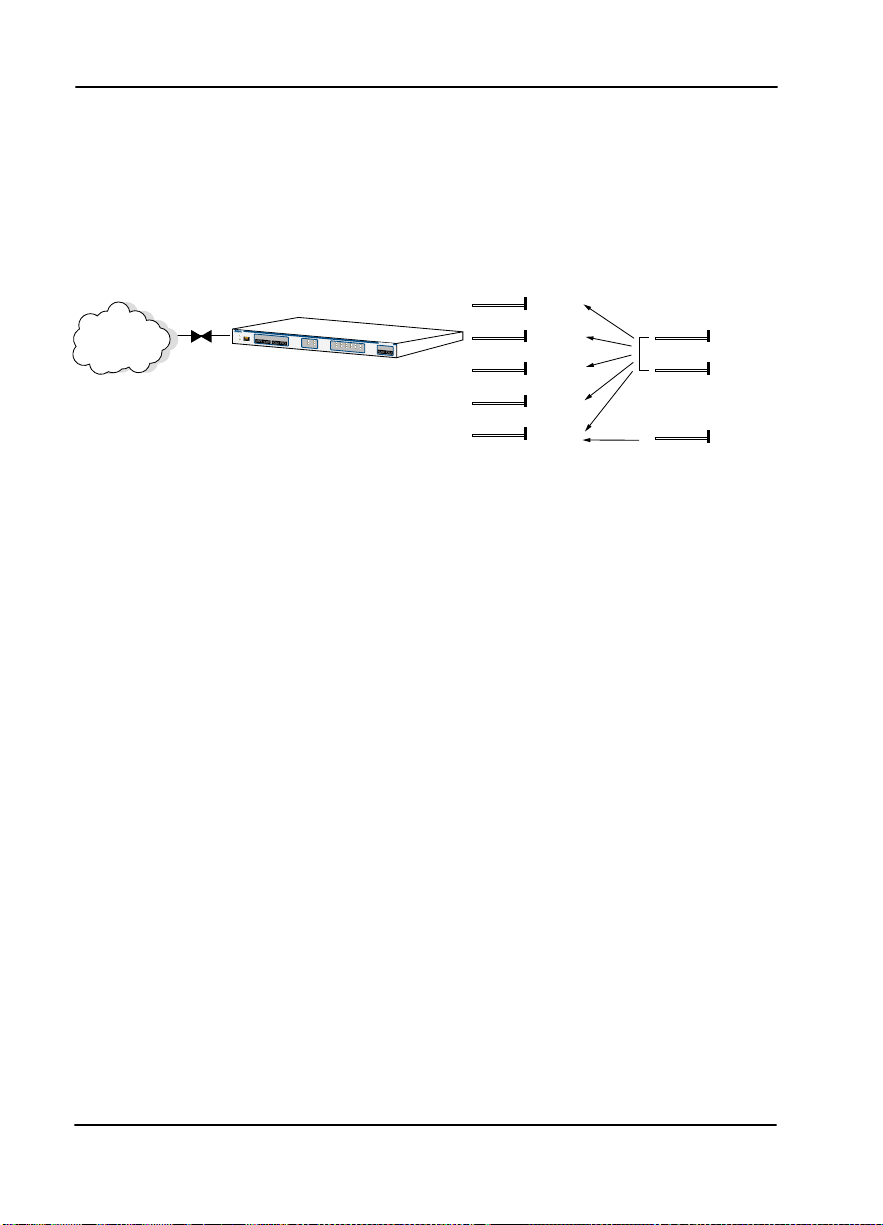
TDU 120e CONFIGURATION APPLICATIONS
The follow ing e xamples illustrate possible configurations of
TDU 120e applications.
Router, PBX, Video Conferencing Application
In this application, the Base Nx/DBU provides a V.35
interface to a router. The PBX is interfaced to the TDU 120e
with the Base DS-1 interface. An OCU DP module and OCU
DP plug-on board provide two switched 56 circuits for video
conferencing. The 10BaseT port allows SNMP network
management over the LAN. See Figure 1-2.
PBX
VIDEO
CONFERENCING
TDU 120e
R
E
M
O
T
E
A
C
C
E
S
S
C
R
A
N
F
E
T
T
W
O
R
K
M
O
N
P
O
R
T
0
.
2
M
I
N
O
N
O
U
T
I
N
A
C
O
O
U
T
O
K
I
N
O
U
T
R
E
I
N
D
O
U
T
T
E
S
T
Y
E
L
O
K
A
L
A
R
M
E
R
R
O
R
N
E
T
W
O
R
K
ST
A
T
U
S
T
D
U
1
T
E
A
L
A
R
2
S
T
M
0
e
A
C
P
O
R
T
1
.
1
0
.
1
M
O
N
0
.
2
1
.
1
1
.
2
1
.
I
3
N
O
U
1
T
.
4
I
N
P
O
O
R
U
T
T
S
T
A
TU
S
ROUTER
10 BaseT LAN
SNMP NETWORK
MANAGEMENT WORKSTATION
Figure 1-2. Bridge, PBX, Video Conferencing Application Set Up
61202156L1-1 TDU 120e User Manual 1-5
Page 30

Chapter 1. Introduction
1-6 TDU 120e User Manual 61202156L1-1
Page 31

Chapter 2
Installation
UNPACK, INSPECT, P OWER UP
Receipt Inspection
Carefully inspect the TDU 120e for any shipping damages. If
you suspect damage, file a claim immediately with the
carrier and then contact ADTRAN Customer Service (see the
front section of this manual for contact information). If
possible, keep th e o riginal shipping c ontainer for use in
shipping the TDU 120e back for repair or for verification of
damag e during shipmen t.
ADTRAN Shipments Include
The following items are included in the ADTR AN shipment:
• The TDU 120e
• 2-line interface cables : A 15-foot, 8-position modular to 8-
position modular
• A DB-25 to modular adapter
• A 6-foot, 8 - position modu lar cable for connection to the
chain-in port
• The User Manual
Customer Provides
• Cables for any expansion modules to be used with the
TDU 120e
• 10BaseT cable for connection to a LAN or router (if you
plan to use remote management features)
61202156L1-1 TDU 120e User Manual 2-1
Page 32

Power Connection
AC powered units: Each TDU 120e AC is equipped with a
captive eight-foot power cord, terminated by a three-prong
plug which connects to a grounded power receptacle.
Power to the TDU 120e AC must be from a grounded 90-120
VAC, 50/60Hz source.
DC powere d un i ts: Each TDU 120e DC unit is provided with
a two-pin power receptacle and mating plug. Power to the
TDU 120e DC is +
48 VDC or +24 VDC.
GROUNDING INSTRUCTIONS
Grounding instructions from the Underwriters' Laboratory UL
1950 3rd Edition are provided in this section.
Chapter 2. Installation
An eq u i p m e n t g roundin g c onducto r th at is not sm a l le r in
size than the ungrounded branch-circuit supply conductors
is to be installed as part of the circuit that supplies the
product or system.
• Bare, covered, or insulated grounding conductors are
acceptable.
• Individually covered or insulated equipment grounding
conductors shall have a con tin uou s outer finish that is
either green, or green with one or more yellow stripes.
• The equipment grounding conductor is to be connected
to ground at the service equipment.
• The attachment-plug receptacles in the vicinity of the
product or system are all to be of a grounding type.
• The equipment grounding conductors serving these
receptacles are to be connected to earth ground at the
service equipment.
2-2 TDU 120e User Manual 61202156L1-1
Page 33

Chapter 2. Installation
• A supplementary equipment grounding conductor shall
be installed between the product or system and ground
that is in addition to the equipment grounding conductor
in the power supply cord.
• The supplementary equipment grounding conductor
shall not be smaller in size than the ungrounded branchcircuit supply conductors.
• The supplementary equipment grounding conductor
shall be connected to the product at the terminal
provided.
• It shall be connected to ground in a manner that will
retain the ground connection when the product is
unplugged from the receptacle.
• The connection to ground of the supplementary
equipment grounding conduc tor shall be in compli an ce
with the rules for terminating bonding jumpers at Part K
or Article 250 of the National Electrical Code, ANSI/
NFPA 70.
• T ermination of the supplementary equipment grounding
conductor is permitted to be made to building steel, to a
metal elec tri cal r ace way syst em, or to any g rou nde d item
that is permanently and reliably connected to the
electrical service equipment ground.
• The supplemental grounding conductor shall be
connected to he equipment using a number 8 ring
terminal.
• The terminal should be fastened to the grounding lug
provided on the rear panel of the equipment.
• The ring terminal should be in st a lle d us ing the
appropriate crimping tool (AMP P/N 59250 T-EAD
Crimping Tool or equivalent).
Do not use this product near water, such as in a wet basement.
For DC-powered devices, the supply power for the product
shall be inst alled near the equipm ent and shall be easily accessible.
61202156L1-1 TDU 120e User Manual 2-3
Page 34

REAR PANEL LAYOUT
Figure 2-1 shows the configuration of the TDU 120e rear
panels of the for both the AC powered unit and the DC
powered unit.
Chapter 2. Installation
Figure 2-1. TDU 120e Rear Panels
2-4 TDU 120e User Manual 61202156L1-1
Page 35

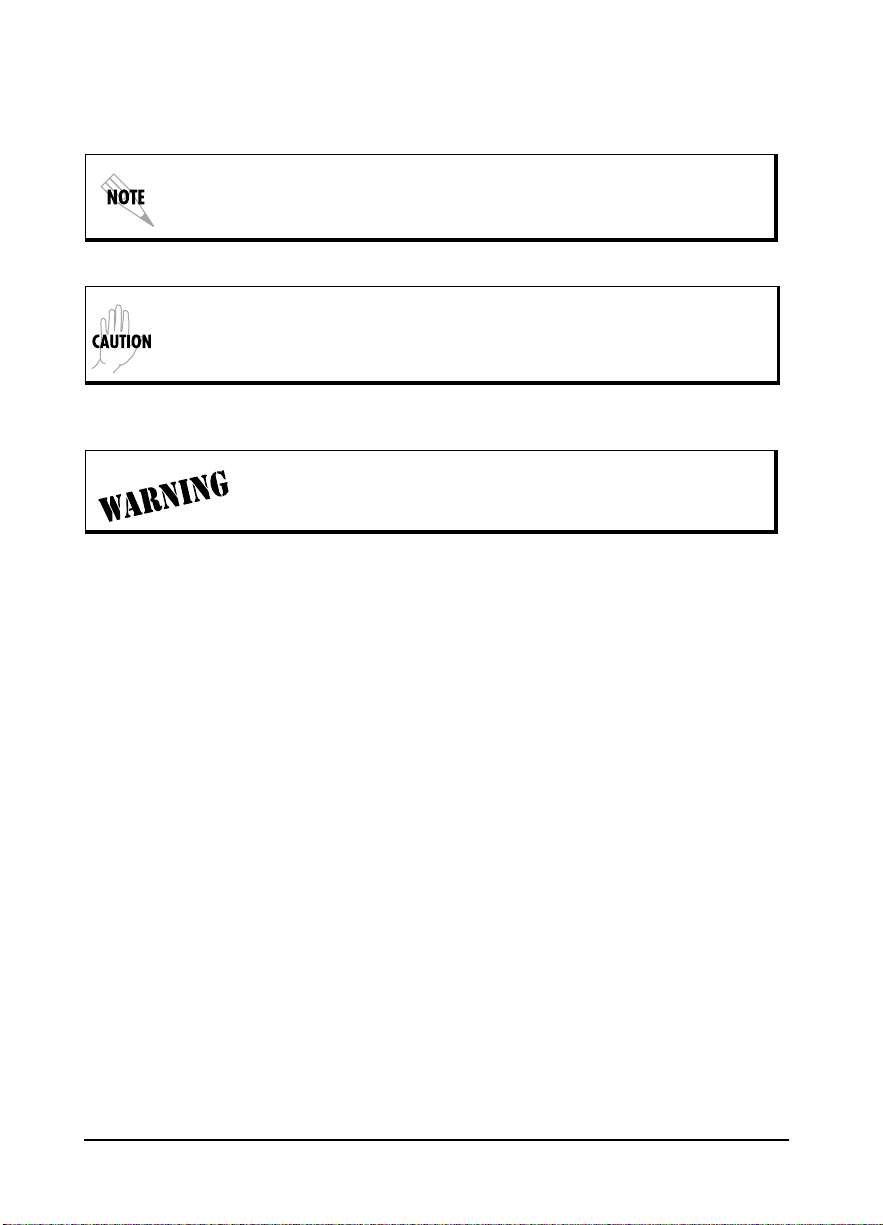
TDU 120e Interfaces
The TDU 120e is equipped with an Nx/DBU data port, a DS1 interface, an option slot, management interfaces, an
external alarm connector, and a T1 interface, in the rear panel.
See Figure 2-2.
PC or Modem
10BaseT
Control
Input
TSU 120e
NI
Chain
Output
Chapter 2. Installation
Chain
Chain
Input
Output
TSU 120e
NI
Network
Network Interface
The Network Interface (NI) port provides the connection to
the T1. This port complies with the applicable ANSI and
AT&T standards. For more information, see Wiring on page
B-1.
Nx56/64 Serial Interface
The Nx56/64 provides a serial V.35 port that operates from
56kbps to 1.536Mbps. This port provides 511 pattern
generation and detection and rem ote loopback capability.
DS-1 (PBX) Interface
The DS-1 Interface provides a T1 for a PBX or other
equipment. This port complies with ANSI T1.102. It can be
software configured for either long-haul or s h ort-h aul.
DS-1
Nx56/64 Nx56/64
Option Option
V.35
PBX
Figure 2-2. TDU 120e Interfaces
DS-1
DS-1
V.35
Control Port Input
The control port input provides an EIA-232 input from a PC
or a modem for contr ol of the TDU 120e. You can also use it
61202156L1-1 TDU 120e User Manual 2-5
Page 36

as a chain input fr om anot her TDU 1 20e or TSU 100 . Fo r more
information, see Wiring on page B-1.
Craft Port
The craft port provides the same functionality as the Control
Port Input. Both the craft port and the control port input may
be connected simultaneously, but only one port may be active
at a time. For more information, see Wiring on page B-1.
Chain Port Output
The chain port output provides an EIA-232 output to chain
control to other TDUs or to TSUs. For more information, see
Wiring on page B-1.
10BaseT Interface
The 10BaseT interface pro v ides the LAN interface for
managing the TDU 12 0e w ith SNMP or T-Watch Pro. For
more information, see Wiring on page B-1.
External Alarm Connector
The external alarm connector allows you to connect an
external alarm device to the TDU 120e. The alarm relay will
activate on any alarm. The relay will remain activated until
the ACO button on the front panel is pushed. For more
information, see Wiring on page B-1.
Chapter 2. Installation
2-6 TDU 120e User Manual 61202156L1-1
Page 37

Chapter 2. Installation
POWER UP TESTING
When shipped from the factory, the TDU 120e is set to factory
default conditions. At the first appl icat io n of power, the unit
automatically executes a memory self-test. A full self-test can
be run from the terminal. A passcode and unit ID may be set
using the UTIL menu.
Self-Test
When... Then...
Initiating a self-test The terminal displays System S elf-test Now
Testing and Memory Test Now Testing. The
test leds are illuminated.
The self-test is completed All LEDs go back to their normal state. The ter-
minal momentarily displays System Self-test
Tests passed.
A failure is detected A list of failures is displayed on the terminal.
The full self-test procedure (invoked from the terminal or TWatch PRO) consists of the following tests:
Board Level Tests
The TDU 120e contains an on-board processor which executes a series of tests checking the circuitry on the board.
RAM and EPROM Tests
Verify on-board circuitry
Unit Level Tests
Front panel LED verification.
Board-to-Board Interface Test
A test pattern is sent fro m the controll er throu gh a loopback
on all other boards and checked on the controller.
This verifies the data path, clocks, and control signals for the
entire chassis.
61202156L1-1 TDU 120e User Manual 2-7
Page 38

Initialization
Set User Passcode
The TDU 120e is designed to operate with or without the use
of a passcode. The default condition is without a passcode.
If the unit is to be remotely accessed using T-Watch PRO, you
must enter a passcode. When managing a number of units, the
passcode can be the sa me for all the units.
The passcode should be a number easily remembered. Once
entered, the passcode is required to acces s any operation
other than viewing. See Set Passcode on page 6-3 for details.
Set Unit Identification
The Unit ID sets the unit to respond to remote control
(controlled by a device other than the front panel or
terminal). If n o Unit ID is recorded, it is not possible to
operate from any remote control device, including the local
PC for T-Watch PRO or SNMP. See Unit ID on page 6-3 for
details.
Chapter 2. Installation
Set Control Port
The TDU 120e can be configured from the control port when
T- Watch PRO, SNMP, or the termina l interface ar e being
used. If the control port is to be used, the control port baud
rate must also be selected.
Chain In (PC)
The unit can be controlled from an external PC connected
directly or via modem to the Chain-In port. When using
Chain-In, the s ele ction of the Control Port baud rate from
9600 (factory default), 1200, 2400, or 4800, 19200, or 38400
must be made usin g the U
NIT CONFIGURATION
menu. See Unit
Menu on page 5-8 for details.
2-8 TDU 120e User Manual 61202156L1-1
Page 39

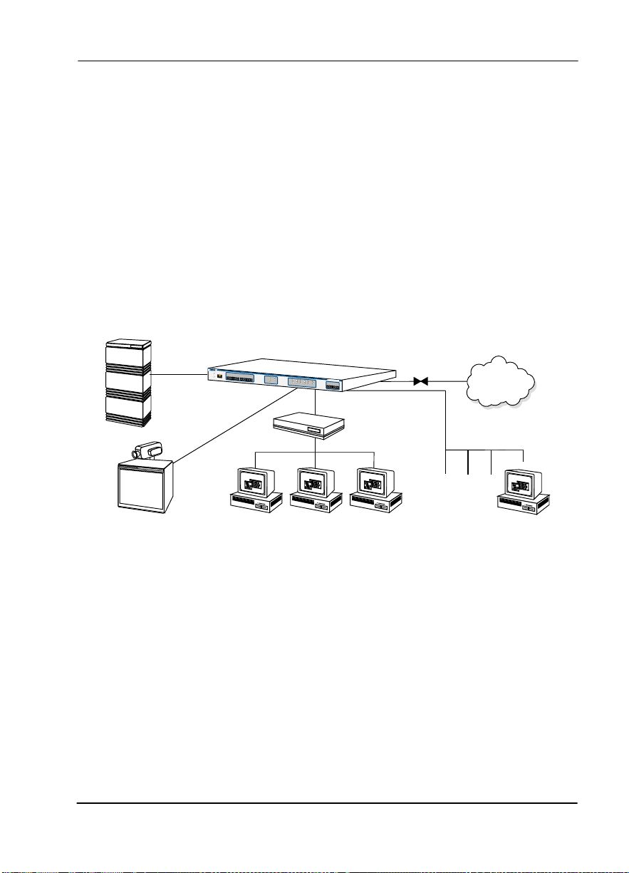
Chain In/Chain Out
TDU 120e units and other TDUs and TSUs can be linked
together to form a chain. Figure 2-3 sho ws an example of a
chain-in arrangement with a PC or a modem. The first TDU
120e in the chain receives controlling input from the PC or
modem.
PC or Modem
Chapter 2. Installation
Control
Input
TDU 120e
Chain
Out
ChainInChain
Out
TDU 120e /
TSU 100/TSU
ChainInChain
Out
TDU 120e /
TSU 100/TSU
Figure 2-3 . Example of Chain-in
Subsequent TDU/TSUs in the chain are in a position to
intake information from another TDU or TSU. This intaking
of information from another TDU in the chain is identified as
Chain In. The baud r a te for the chained units must match
that of the first unit.
Unless locked out externally, the front panel can also control
the unit.
At this point, the Un it Init ia liza ti on procedure is conclu ded .
If the unit is to be configured remotely, there are no
additional items necessary to complete prior to executing
remote configuration.
The Passcode, the Unit ID, and the Co ntrol Port settings are
stored in a nonvolatile memory. This ensures they are
operable for subsequent power-up sequences.
61202156L1-1 TDU 120e User Manual 2-9
Page 40

Normal Power-Up Procedure
After the unit has been put into operation with the initial
power-up and initialization, subsequent power -up procedure
includes only the Power-Up self-test followed by the request
for a passcode (password) if this option was selected during
initialization.
Chapter 2. Installation
Type the previously recorded passcode and press
Enter
.
2-10 TDU 120e User Manual 61202156L1-1
Page 41

Chapter 3
MENU FEATURES
The TDU 120e uses a VT 100 type terminal to display control
and monitor menus. Initiate this mode by key ing in <CTRL>
PTT on the terminal onc e it is connec ted to the Control In or
Craft port.
When you begin the telnet session, you will be prompted for
a password. The default password is ADTRAN. You can
change this password using the M
For detailed information on this method of control, see
Telnet/Terminal Main Menu on page 3-6.
You can also connect to the TDU 120e via telnet. Before
attempting to connect via telnet, first define the IP address,
the default gateway, and the subnet mask.
Operation
ANAGEMENT
submenu.
See D
EFAULT UNIT PASSCODE
details. The telnet sess ion w ill time-o ut after a predefine d
value that is a ls o set in the M
Only one tel net session can be a ctive at a time.
61202156L1-1 TDU 120e User Manual 3-1
in Table 8-1 on page 8-3 for
ANAGEMENT
menu.
Page 42

Sample Terminal Screen with TDU 120e M enu
An example of a PC screen with a TDU 120e menu is shown
in Figure 3-1.
Main Menu
1) Status
2) Config
3) Util
4) Test
5) Remote Menu Access
6) Management Config
7) Flash Download
8) Quit Session
Command:
Figure 3-1. Sample Terminal Screen with TDU 120e Menu
General Menu Operation
The TDU 120e uses a multilevel menu structure containing
both menu items and data f ie lds. All menu operations an d
data are displayed on the terminal.
Chapter 3. Operation
Select and Activate a Menu Item
T o choose a menu item, place the cursor on the desired menu
item by:
• pressing the number corresponding to the menu item, or
• using the up and down arrows.
Table 3-1 on page 3-3 describe how to activate the alarm list
option from the Status Menu.
Figure 3-2 on page 3-3 shows an example of basic menu
travel.
3-2 TDU 120e User Manual 61202156L1-1
Page 43

Chapter 3. Operation
Table 3-1. Activating Al arm List from Statu s Menu
Step Action Result
Activate the STATUS menu using the
1
arrow keys or by pressing 1.
The cursor will flash on the number next to the activated selection.
Press Enter. The status subme nus will dis -
2
play.
Use the arrow keys to view submenu
3
items.
Choose an item on the submenu
4
such as ACTIVE ALARMS.
The cursor will flash on the number next to the activated selection.
Press Enter. The active alarm list will display.
5
View the Alarm List.
6
.
1) NETWORK (NI) PERFORMANCE REPORTS
2) NETWORK (NI) ERRORS
3) ACTIVE ALARMS (ALARM LIST)
4)VIEW HISTORY END OF LIST
STATUS 5) PORT STATUS
6) REMOTE PORT
7) CLEAR PORT ALARM
8) ETHERNET STATUS
Figure 3-2. Example of Basic Menu Travel
61202156L1-1 TDU 120e User Manual 3-3
Page 44

Chapter 3. Operation
Y ou can edit data fields preceded by a colon (:). T o edit a data
field, perform the steps in Table 3-2:
,
Table 3-2. Editing a Data Field
Step Action Result
Position the cursor on the sub-
1
menu item number and press
.
Enter
Using the space bar, scroll to scan
2
the available value settings.
When the desired value is dis-
3
played in the data field position,
press
to set that value.
Enter
Another submenu field may be
selected, or press E
SCAPE
to return
to the submenu.
Exit Any Menu Field Operation Or Display
Press
Escape
as ma ny times as required to re t u rn to the
desired menu level.
The cursor moves to the data
field (to the right of the submenu item name).
The value settings display
one-at-a-time in the data field
position.
When the value is set, the cursor moves back to the submenu item position. This
indicates the operation is
complete.
3-4 TDU 120e User Manual 61202156L1-1
Page 45

Data Port Identific ation
When configuring the unit, menu selectio ns will include
opti ons from da ta port submenus. Se le cting of dat a p o rts is
necessary because the TDU 120e uses a Slot-Port method to
identify the data port the menu item is referencing. If a
module containing a PBX DSX-1 option card with an Nx56/
64 plug-on interface is installed in the option slot, it would be
designated as:
DSX-1 Passthru (1.1)
Where slot=1 and port =1.
The DSX-1 i s located in the option slot an d is the f i rst port i n
that slot.
Nx56/64 (1.2)
Where slot=1 and port=2.
The Nx is located in the slot and is the second por t in that
slot.
Chapter 3. Operation
The ports that are built into the TDU 120e are referenced as
Slot 0. The Nx/DBU is designated as 0.1 and the DS-1 is
referenced as 0.2.
61202156L1-1 TDU 120e User Manual 3-5
Page 46

Menu Structure
Telnet/Term inal M a in Menu
The TDU 120e uses a multilevel menu structure containing
both menu items and data f ie lds. All menu operations an d
data displa y in the t erm ina l win dow.
The first menu displayed after the telnet/terminal session is
established is the Main menu. See Figure 3-3. The default
telnet/terminal password is ADTRAN.
ADTRAN - TDU 120e
Password: XXXXXXXX
Main Menu
1) Status
2) Config
3) Util
4) Test
5) Remote Menu Access
6) Management Config
7) Flash Download
8) Quit Session
Chapter 3. Operation
Figure 3-3. Telnet/Terminal Main Menu
.
Only one telnet/ te rmi nal session may be active at a tim e.
3-6 TDU 120e User Manual 61202156L1-1
Page 47

Menu Options
Chapter 3. Operation
The opening menu is the access point to all other operations.
Each Main menu item has several functions and submenus to
identify and access specific parameters.
Status
Displays all relevant information for the network and DTE
interfaces. For detailed information on status options, see
Chapter 4, Status Menu on page 4-1.
Config (Configuration)
Displays sets the TDU 120e operational configuration,
including all net work interface parameters, the allocation of
the DS0s, and the port parameters. For detailed information
on configuration options, see Chapter 5, Configuration Menu
on page 5-1.
Util (Utilities)
Displays and sets system parameters. For deta iled inform ation on utility options, see Chapter 6, Utility Menu on page 6-
1.
Test
Initiates different types of unit tests and displays test results
in the terminal window. For detailed information on test
opti ons, se e Chapter 7, Test Menu on page 7-1.
Remote Menu Access
Displays Telnet menus for a remote devic e. For detailed
information, see Remote Menu Access on page 8-1.
Management Configuration
Displays management information. For detailed information,
see Management Configuration on page 8-1.
Flash Download
Allows you to manually perform a Flash download. For
detailed information, see Flash Download on page 8-6.
Quit Session
Terminates the telnet/terminal session.
61202156L1-1 TDU 120e User Manual 3-7
Page 48

FRONT PANEL
The TDU 120e front panel monitors operation and controls
the configuration of the unit. The TDU 120e front panel is
shown in Figure 3-4.
CRAFT
Connection
For
Terminal
NETWORK MON
IN OUT
Network
Monitor Jack
IN OUT
REMOTE
ACCESS
ACO
Alarm
Cut Off
Control Port
Active Unit
Descriptions of each part of the front panel follow.
ACO Switch
The Alarm Cut-Off switch deactivates the alarm relay after
an alarm condition has occurred. If the alarm that activated
the alarm relay is cleared, then reoccurs, the alarm relay will
reenergize.
PORT 0.2 MON
IN OUT
IN OUT
DS-1
Monitor Jack
Chapter 3. Operation
TD
U
1
20
eA
OK
RED
TEST
ALARM
ERROR
NETWORK STATUS
Network
Status LED's
YEL
OK
TEST
ALARM
0.1
0.2
1.1
1.2
1.3
PORT STATUS
Port Status
1.4
LED's
PORT 1.1 MON
IN OUT
IN OUT
Port 1.1
Option Card
Monitor Jacks
C
Figure 3-4. TDU 120e Front Panel Layout
Remote LED
The remote LED (yellow) indicates a management session
(terminal mode or teln et) i s acti ve. The LED does n ot acti va te
(turn on) during SNM P sessions.
Craft Port
The Craft Port is used as an EIA-232 port to connect the unit
to a computer, a modem, or to another TDU/TSU
multiplexor or a TSU 100.
Network Monitor Jack
This jack connects the unit to the network.
3-8 TDU 120e User Manual 61202156L1-1
Page 49

DS1 Monitor Jac k
This jack connects the unit to a PBX or other terminal
equipment.
Network Status LEDs
The Net work status LEDs display the operational condition
of the network interface located on the controller board in the
unit.
Network Status LED Display Indicates that...
Chapter 3. Operation
OK (green)
Test (yellow)
Error (red)
Alarm (red)
the operation is in the normal mode and no
errors have been detected.
the network interfaces is operating in a test
mode. This includes a self-test or a test loopback. When illuminated, this LED also indicates that normal data flow is not occurring
on the network interface.
an error has occurred, such a s BPV, OOF, or
CRC.
an alarm condition has been detected. Any
alarm condition will activate the alarm relay
for the external alarm device. When the alarm
condition is no longer valid, the OK LED activates (turns on). To view an alarm condition,
select the active alarm menu item.
If the alarm conditions have been corrected, the alarm which
caused the activation of the Alarm LED can be viewed under t he
U
NIT HISTORY
menu.
61202156L1-1 TDU 120e User Manual 3-9
Page 50

Port Status LEDs
Port Status LED Display Indicates that...
Chapter 3. Operation
OK (green)
Test (yellow) one of the interfaces is operating in a te st
Alarm (red)
the operation is in the normal mode and no
errors have been detected.
mode. This includes a self-test or a test loopback.
When illuminated, it also indicates that normal
data flow is not occurring in at least one of the
module ports.
an alarm condition has been detected. Any
alarm condition will activate the alarm relay for
the external alarm device. When the alarm
condition is no longer valid, the OK LED activates (turns on).
To view an a larm condition, selec t the active
alarm menu item.
If the alarm conditions have been corrected,
the alarm which caused the activation of the
Ala rm LED ca n be viewed under the U
menu.
TORY
NIT HIS
-
Port 1.1 Option Card Mo ni to r Jacks
These are used to connect option cards to the computer.
3-10 TDU 120e User Manual 61202156L1-1
Page 51

ALTERNATE METHODS OF CONTROL
T- Watch Pro (ADTRAN PC Program)
T-Watch PRO is the ADTRAN PC control program. It
provides complete control over the configuration of the TDU
120e using a graphical interface. The T-Watch Pr o program
displays the same status and performance data as the
terminal screen. This data is displa yed in tables a nd gra phs .
The T-Watch Pro program has the follo wing capabilities:
• Interfaces with a modem which permits dialing into a
remote TDU 120e location to configure the unit or read
the status or performance of the unit.
• Receives traps from any TSU product.
• Records and creates display performance data over a 30
day period.
• Accesses u nit s v ia th e lo cal area network.
Setting up the TDU 120e to Work Over a LAN
To s et up the TDU 1 20e to work with T-Watch Pro ove r the
LAN, follow these steps:
Chapter 3. Operation
Step Explanation
Set the Unit ID using the Terminal or Telnet. See
1
ID
on page 6-3 for details.
Set control port interface to Normal (10BaseT) or
2
SLIP (chain-in port).
Configure the IP address, default gateway, and sub-
3
net mask.
Follow the installation instructions for T-Watch PRO to
4
start the program and connect to the unit.
61202156L1-1 TDU 120e User Manual 3-11
Unit
Page 52

Chapter 3. Operation
Setting up the TDU 120e to Work Over an EIA-232 Connection
To s et up the TDU 120e to work with T-Watch PRO ove r a
direct EIA-232 connection, follow these steps:
Step Explanation
SNMP
1
2
3
4
The ADTRAN TDU 120e supports the Simple Network
Management Protocol (SNMP) through the 10BaseT or chain
in (SLIP) interface. See Appendix A SNMP, on page A-1, for
more information.
To use SNMP with the TDU 120e, follow these steps:
Step Explanation
Set the Unit ID and set a passcode. See
Passcode
Set the control port rate to the same setting as
the PC Com port.
Connect the PC Com port to the Chain-In port on
the TDU 120e using the DB-25 adapter and modular cable provided.
Follow the in stallation instruction s for T-Watch
PRO to start the program and connect to the unit.
1
Set the control port to either Normal (10BaseT)
or SLIP (Chain-in port)
on page 6-3.
Set
2
3
3-12 TDU 120e User Manual 61202156L1-1
Set the IP address, default gateway, and subnet
mask through the Terminal mode.
Load the appropriate MIB browser into the Network Management Station. T he MIB browser
issues SNMP gets to and sets the TDU 120e.
See the ADTRA N webpage at:
http://www.adtran.com.
Page 53

Chapter 4
Status Menu
The S
menu br anch allows yo u to view the status o f the
TATUS
TDU 120e operation. See Figure 4-1.
%AS
1) NETWORK (NI) %EF
PERFORMANCE REPORTS ES
SES
2) NETWORK (NI) ERRORS UAS NETWORK (NI)
1)STATUS RED ALARM
3) ACTIVE ALARMS LOSS OF SIGNAL
END OF LIST
4)VIEW HISTORY (HISTORY LIST)
END OF HISTORY
1) DTE DATA CLOCK
5) PORT STATUS Nx/DBU (0.1) 2) DTE STATUS
3) DTE PORT RATE
6) REMOTE PORT 4) DBU DATA/CNTRL
5) DBU CONTROL
6) DBU STATUS
DS-1 (0.2) DS-1 ERRORS
7) CLEAR P ORT ALARM
8) ETHERNET STATUS
Figure 4-1. Status Menu Tree
Menu flow is normally depicted from left to right. At every
level of the menu, pressing
previous menu level. Press
system to the M
61202156L1-1 TDU 120e User Manual 4-1
AIN
menu.
Escape
Escape
returns the system to the
repeatedly to return the
Page 54

Network Performance Reports
The Network Interface Performance Reports display the user
copy of the performance data. The TDU 120e maintains this
performance data on the network in compliance with ANSI
T1.403 and AT&T document TR54016. The data displayed is
data accumulated over the last 15 minutes and over the last
24 hours.
15MIN/24 HR
Chapter 4. Status Menu
%AS %EF -
ES SES UAS -
Where Means
Figure 4-2. Network Interface Performance Report
0.0/NA
0.0/NA
0/NA
0/NA
900/NA
%AS Percentage of available seconds
%EF Percentage of error free seconds
ES Number of errored seconds (1 or more
errors/second
SES Number of severely errored seconds
(more than 320 errors/second)
UAS Number of unavailable seconds (10 or
more consecutive seconds)
If insufficient time has passed to collect data, NA displays. Continue with standard operating procedures to exit the display.
4-2 TDU 120e User Manual 61202156L1-1
Page 55

Network Inter f ace Errors
Chapter 4. Status Menu
The NI E
work Interface (NI) detects. A blinking CSU error LED indicates that network errors are detected.
The asterisk (*) above an item indicates the type of errors
detected. The error types are shown in Table 4-1.
Active Alarms
This menu item dis p lays a lis t o f cu rrent a larm s report ed by
either the base controller or any of the ports. If no alarms are
current, using this menu item displays
submenu displays the types of errors the Net-
RRORS
Table 4-1. NI Error Types
Error Type Description
CRC CRC-6 bit errors based on the FDL. Thi s is
valid only in ESF mo de.
BPV Bipolar violations
XSO Excess zeros
FER Framing errors
End of List
.
The display in Table 4-2 on page 4-3 includes two text fields.
The left field is the alarm source. The right field is the alarm
message. A list of alarm messages is found in Appendix C,
System M essages on page C-1.
If one or more of the Alarm LEDs are illuminated, an alarm is
present. Press
61202156L1-1 TDU 120e User Manual 4-3
Escape
to return to the previous menu item.
Table 4-2. Alarm Message Display
ACTIVE ALARMS
NETWORK (NI)
NETWORK (NI)
END OF LIST
LOSS OF SIGNAL
RED ALARM
Page 56

View History
Chapter 4. Status Menu
This menu item b oth displa ys and clear s the accu m ula ted
status changes of the unit.
V
IEW HISTORY
in the unit, including the date, time, and type of change. The
unit also records for viewing the date and time an alarm
became active and inactive, as well as the date and time of
test activation and deactivation.
To clear the V
Po rt Status
P
ORT STATUS
ports. For example, the Nx/DBU interface monitors the RTS,
CTS, TD, and R D, along with other signal lines. When a port
is selected, the terminal indicates if the signal is present.
The base Nx interface offers the status screen listed in this
section. When using other op tion cards, re f e r to the
appropriate separate manual for a definition of any status
screens offered.
The Port Status of Nx/DBU shows how to use this item.
Nx/DBU (0.1) Menu Items
DTE Data/Clock
An asterisk (*) indicates an active status of the following
lines:
displays a history of the last 20 status changes
IEW HISTORY
display, press C.
displays the signals mon i tored on th e data
• TXD -Transmit data from the DTE
• RXD - Receive data toward the DTE
• XSO - Excess zeros from the DTE
• LCK - Lock Status of the phase locked loop
4-4 TDU 120e User Manual 61202156L1-1
Page 57

Chapter 4. Status Menu
DTE Status
An asterisk (*) indicates an active status of the following
lines:
• RTS - Re quest to sen d from D TE
• CTS - Clear to send to DTE
• DCD - Data carrier detect to DTE
• DSR -Data set ready to DTE
DTE Port Rate
The Port Rate displays the current setting of the Nx port.
Continue with standard operating procedures to exit the
display.
DBU Data/CNTRL
An asterisk (*) indicates an active status on the following
lines:
• TXD - Transmit data to the DCE
• RXD - Receive data from the DCE
• DCD - Data carrier detect from the DCE
• RI - Ring Indicate from the DCE
DBU Control
An asterisk (*) indicates an active status on the following
lines:
• RTS - Re quest to sen d t h e DCE
• CTS - Clea r to send from t h e D CE
• DTR - Data terminal ready to the DCE
• DSR - Data set ready from the DCE
DBU Status
• DBU SECS - Total seconds in current DBU session
• IN DBU -YES/NO i ndication of act ive DBU status
61202156L1-1 TDU 120e User Manual 4-5
Page 58

DS-1 (0.2) Menu Items (DS-1 Errors)
• CRC - An asterisk displays under the CRC if there are
CRC errors in extended superframe format (ESF) mode.
If the DS-1 is configured for D4 Frame format, the
terminal displa ys N/A.
• BPV - An asterisk displays under the BPV if the DS-1
detects bip olar viol ations .
• SLIP - An asterisk displays under the SLIP if the DS-1
detects frame slip s. T his is c au sed by multiple cloc k
sources in the applic atio n.
• FER - An asterisk displays under the FER if the DS-1
detects frame bit syn chroniza t i on erro rs.
Remote Port
Chapter 4. Status Menu
R
EMOTE PORT
remote port. This is useful for troubleshooting
communication sessions, and for verifying cabling.
• RX -Characters received at remote port
• ID - Unit ID received at remote port
• CRC - Correct CR C receiv e d
• PC - Correct passcode rece ived
• TX - Characters transmitted fro m the remot e port
Clear Po rt Alarm
Clears the L
been removed from the TDU 120e chassis.
displays th e st atus of activit y on the Con tr ol I n
INK FAILED
alarms on option modules that have
4-6 TDU 120e User Manual 61202156L1-1
Page 59

Ethernet Status
• TX - Indicates that data is being transmitted from the
10BaseT port.
• RX - Indicates that data is being received by the 10BaseT
port.
• LNK - Indicates the current status of the 10BaseT link
integrity test (this should always be on when the unit is
connected to a functional 10BaseT hub).
• CPU - Active when the CPE is accessing the 10BaseT
interface.
Chapter 4. Status Menu
61202156L1-1 TDU 120e User Manual 4-7
Page 60

Chapter 4. Status Menu
4-8 TDU 120e User Manual 61202156L1-1
Page 61

Chapter 5
Config uration Menu
The C
ONFIGURATION
configuration, including all network interface parameters,
the allocation of the DS0s, and the port parameters. See the
Figure 5-1 on page 5-2.
Menu flow is normally depicted from left to right. At every
level of the menu, pressing
previous menu level. Press
system to the M
menu sets the TDU 120e operational
returns the system to the
repeatedly to return the
AIN
Escape
Escape
menu.
61202156L1-1 TDU 120e User Manual 5-1
Page 62

1) FORMAT
2) CODE 1) CONTROL PORT RATE
3) YELLOW ALARM 2) TRAPS
4)TRANSMIT PRMS 3) ACCESS
5) TIMING MODE 4) INIT MODEM
6) UBRiTE 5) CONTROL PORT
6) SET LINE BUILD OUT 6) IP ADDRESS
1) NETWORK (NI) 7) INBAND L00PBACK 7) SUBNET MASK
8) BIT STUFFING 8) DEFAULT ROUTER
2) UNIT 9) SLIP RATE
10) SLIP FLOW CONTROL
3) MAP EXCHANGE OFF 11) PROXY TRAPS
4) MAP IN USE 1) MAP A @:HH:MM
AUTO 2) MAP B @:HH:MM
3) CONFIG 5)DS0 M APS 1) COPY MAP A TO TEMP MAP
2) COPY MAP B TO TEMP MAP
3) CREATE TEMP MAP 1) DSO RATE
4) REVIEW MAP A 2) TX CL K CONTROL
5) REVIEW MAP B 3) DATA
6) REVEIW TEMP MAP 4) CTS
7) EDIT TEMP MAP 5) DCD
8) APPLY TEMP MAP TO MAP A 1) Nx56/64 CONFIG 6) DSR
9) APPLY TEMP MAP TO MAP B 7) “0” INHIBIT
1) Nx/D B U (0.1) 9) TX CLK SOURCE
Chapter 5. Configurat ion Menu
8) INBAND MODE
2) DBU CONFIG 1) BACK UP M ODE
6) PORT CONFIG 2) BACKUP ON
2) DS-1 (0.2) OPTION PORTS 1) FORMAT 3) PATTERN VERIFY
2) CODE 4) BACKUP DELAY
3) YELLOW ALARM 5) RESTORE DELAY
4) LINE LENGTH 6) RETRY DELAY
5) INBAND L00PBACK 7) NUM RETRIES
6) ROB BIT SIGNL 8) BACKUP TESTING 1) BACKUP TEST
7) RBS START 9) W KEND LOCKOUT 2)TEST HOUR
8) RBS END A) EN ABLE HR 3)TEST DAY
B) DISABLE HR
C) TRAP IN DBU
Figure 5-1. Configuration Menu Tree
5-2 TDU 120e User Manual 61202156L1-1
Page 63

NETWORK (NI)
This menu item acces se s the configura tion of parame ters
associated with the network interface in the base unit. There
are eight submenu items that incl ude setting the format, the
line build out (LBO), and the timing mode. Submenu items
do not include setting the parameters which may be
necessary for a secondary interface (DS-1 Passthrough, etc.).
Network (NI) Menu Items
FORMAT
Sets the frame format for the NI.
Choices: D4 and ESF.
D4 is equivalent to superframe format (SF).
CODE
Sets the line code for the NI.
Choices: A MI and B8ZS.
Chapter 5. Configuration Menu
YELLOW ALARM
Enables and disables the transmitting of yellow alarms.
Choices: ENABLED and DISABLED.
TRANSMIT PRMS
Enables and disables the sending of PRM data on the facility
data link (FDL). The PRM data continues to be collected even
if Transmit PRMS are disabled (possible only with ESF Format).
Choices: Off and On.
TIMING MODE
Selects the clock source for transmission toward the network
from the NI. See TDU 120e Clock Sources on page 5-4 for a
description of the timing choices.
Choices: Network, B a se DTE , Base DS- 1, Normal (CSU), UBR1TE, Interna l, and Secondary (SI).
61202156L1-1 TDU 120e User Manual 5-3
Page 64

TDU 120e Clock Sources
The TDU 120e is operable from various clock sources,
permitting it to perform properly in many different
applications. Set the network interface clocking options with
the clocking options set by the Network (NI) Configuration
menu options.
The following clock source options are available:
• Network Timed
• Base DS-1
• Base DTE Timing
• Internal Timing
• Secondary Timing
• Normal (CSU)
• U-BR1TE
The selected clock option always designates the clock source for
transmission. Clocking necessary for receiving data is always recovered fro m incoming data.
Chapter 5. Configurat ion Menu
Network Timed
The network is the source of timing. The received data
clocking is looped back to the network where it is used to
determine the transmission timing. This option is also
referred to a s loop tim ed as the tr ansmission clock is de ri ved
from the received clock. See Figure 5-2.
OSC
T1 XMIT
(DS1)
T1 Receive
Network
Interface
Nx56/64
DTE CLOCK
DTE
DS-1 PBX
PBX
Secondary
Interface
(OPTION)
Figure 5-2. Network Timed Clock Source
5-4 TDU 120e User Manual 61202156L1-1
Page 65

Chapter 5. Configuration Menu
Based DS-1
The PBX is the source of timing. The TDU 120e uses the clock
derived by the Base DS-1 interface for transmission timing.
See Figure 5-3.
OSC
T1 XMIT
(DS1)
T1 Receive
Network
Interface
(OPTION)
Nx56/64
DTE CLOCK
DTE
DS-1
PBX
Figure 5-3. DS-1 Timed Clock Source
Base DTE Timing
The Base DTE is the source of timing. The TDU 120e uses the
incoming DTE clock to determine the transmission timing.
This is typically used in applications w here it is ne c essa ry to
have the DTE as the primary clock source (such as limited
distance line drivers). See Fi g u re 5-4.
OSC
T1 XMIT
(DS1)
T1 Receive
Network
Interface
Nx56/64
DTE CLOCK
(OPTION)
DS-1
DTE
PBX
Figure 5-4. Base DTE Timing Clock Source
61202156L1-1 TDU 120e User Manual 5-5
Page 66

Chapter 5. Configurat ion Menu
Internal Timin g
The TDU 120e is the source of timing. The TDU 120e is
configured to us e its o w n in ter na l os cillat o r as th e so u rce of
timing. Applications include priv a te line driver circuits
where one end is set to network and the other to internal. See
Figure 5-5.
OSC
T1 XMIT
(DS1)
T1 Receive
Network
Interface
(OPTION)
Nx56/64
DTE CLOCK
DTE
DS-1
PBX
Figure 5-5. Internal Clock Source
Secondary Timing
The secondary interface is the source of timing. The TDU
120e uses the clock derived by the secondary interface for
transmission timing. See Figure 5-6.
Figure 5-6. Secondary Clock Source
5-6 TDU 120e User Manual 61202156L1-1
Page 67

Chapter 5. Configuration Menu
Normal (CSU) Timing
The typical timing option arrangement is sho wn in
Figure 5-7. The PBX is looped timed sending data to the TDU
120e which is actually synchronous to the received data. The
Network Interface (NI) is the actual source of all timings.
This timing option is the same as that typically used for
CSUs. This is the preferred mode for use with a PBX
application.
This timing mod e w orks equa ll y w ell whe n the PB X is t he
source of timing. In that conf iguration the network would
not be providing tim ing.
OSC
T1 XMIT
(DS1)
T1 Receive
Network
Interface
(NI)
Nx56/64
DTE CLOCK
DS-1
Secondary
Interface
(SI)
(OPTION)
(IO PB)
PBX
DTE
PBX
Figure 5-7. Normal (CSU) Ti ming
The network interf ace and secon da ry i nterf ace clocking options
are set by using the Network (NI) Configuration menu options.
U-BR1TE
The U-BR 1TE timing selection works like Normal (CSU)
except th at timing is derived from th e U inter f ac e o n po r t 1.1.
Set Line Buildout
Selects the line build-out for the network interface. In A
UTO
mode, the TDU 120e sets the LBO based on the strength of
the receive signal and displays the selected value. Choices:
0.0 dB, 7.5 dB, 15 dB, 22 dB, and Auto.
61202156L1-1 TDU 120e User Manual 5-7
Page 68

Unit Menu
Chapter 5. Configurat ion Menu
In order to activate the -36 dB receiver sensitivity, the LBO
should be set to AU TO. This feature is useful in a point-to-point
application where no network elements are involved. If a network
element such as a Smart Jack is installed on the circuit, the LBO
should be set to 0 dB.
Inband Loopback
Sets unit to acce pt or r ej ect the ne twork inte rf ace l oop-up and
loop-down codes as defined in ANSI T1.403.
Choices: Accept or Reject.
Bit Stuffing
When enabled, bit stuffing causes the TDU 120e to monitor
for ones (1s) density violations and insert a one (1) when
needed to maintain 1s at 12.5%.
Choices: Enable or Disabl e .
The U
menu changes the baud rate of the Control In port
NIT
and the setup of the Dial Out port.
The menu items are:
Control P ort Rate
Sets the baud rate for communication with the PC or modem.
Choices: 1200, 2400, 9600, 19200, and 38400 kbps.
Traps
Enables or disables the transmission of trap messages.
Choices: E nable and Disable
Access
Sets the method of co nnec tion fr om the TDU 120e to T-Watch
or SNMP.
Choices:
Direct - Used if connected directly to the PC.
Dial - Used when connection is throug h a modem. T he dial
string is entered from T-Watch or SNMP.
5-8 TDU 120e User Manual 61202156L1-1
Page 69

Chapter 5. Configuration Menu
Init Modem
Allows you to choose an industry standard or a custom initialization string for a modem connected to the control port.
Choices: Industry standa rd and Custom Initi alization String
Control Port
Selects the TCP/IP physical interface; Normal (10BaseT
Ethernet) or SLIP using the EIA-232 serial port.
Choices: Normal or SLIP
If this option is set to SLIP, the EIA-232 port cannot be used as
a terminal interface.
IP Address
This is the IP address that uniquely identifies the TDU 120e
on a TCP/IP network. This address is composed of four decimal numbers, each in the range of 0 to 255, separated by periods. This value is used for either the 10BaseT Ethernet or
SLIP interface, depending on the IP interface setting.
Subnet Mask
This defines which part of a destination IP address is the Network number. It is used along with the TDU 120e IP address
to determine which nodes must be reached through the
default IP Gateway. This value is set to 0.0.0.0 when t h e IP
interface option is set to SLIP.
Default Router
All IP Packets destined for nodes not on the TDU 120e unit’s
local network are not forwarded through this IP address.
Normally, this address defines a router connected to the TDU
120e unit’s local network. This v al ue is ignored when the IP
interface is set to SLIP.
SLIP Rate
This sets the baud rate for the Chain-In port w hen used as the
SLIP connection for SNMP management.
Choices: 1200, 2400, 4800, 9600, 19200, 38400
61202156L1-1 TDU 120e User Manual 5-9
Page 70

SLIP Flow CTL
This is used to activate flow control on the Chain-In port
when used as the SLIP interface. Hardware mode uses RTS
and CTS.
Choices: None, Hardware
Proxy Traps
This determines whether traps are forwarded to the IP Interface from units being “proxied” for.
Choices: Enable, Disable
Map Excha nge
Chapter 5. Configurat ion Menu
The M
AP EXCHANGE
menu en a b l e s and se ts the auto matic
time of day map switch. The unit provides selection of the
hour, minute, an d secon d s for t he map swi tching to take
place.
The menu items are:
OFF
Indicates the map in use does not c hange. The Automatic
Map Change feature is disabled.
AUTO
Indicates that the map in use will change at a user-selected
time of day. The Automatic Map Change feature is enabled.
Explanation:
When A
is selected, the unit displays the screens to set
UTO
times for switching.
After editing Map A, press
to reco r d th e Map A sett ings
Enter
and activate the selection fields for Map B. Use the same
operation to edit switching time for Map B.
When ESF is used with an FDL channel between units, the
units automatically coord inate the automatic map switch by
sending a map switch command from end-to-end over the
FDL. O nly one end needs to be set to A
for this to work.
UTO
5-10 TDU 120e User Manual 61202156L1-1
Page 71

Map In Use
This menu item controls the DS0 map the TDU 120e uses and
displays the map in current use.
DS0 Maps
The DS0 maps designate which DS0s are assigned to which
port. The three maps are:
DS0 Map A - Default Map
DS0 Map B - Alternate Map
Temp - Temporary map used as a scratch pad
DS0 Maps Configuration Menu
The DS0 maps configuration menu t akes advantage of the
24-line VT 100 display. Upon entering this menu, the current
Temp (temporary) map displays and is followed by nine
selections tha t you c an use for configuring and reviewing
map information. See Figure 5-8.
Chapter 5. Configuration Menu
TEMP MAP
DS0#
PORT
1
IDLE
2
IDLE
3
IDLE
4
IDLE
5
IDLE
6
IDLE
7
IDLE
8
IDLE
9
IDLE
10
IDLE
11
IDLE
12
IDLE
1) COPY MAP A TO TEMP MAP
2) COPY MAP B TO TEMP MAP
3) CREATE TEMP MAP
4) REVIEW MAP A
5) REVIEW MAP B
6) REVIEW TEMP MAP
7) EDIT TEMP MAP
8) APPLY TEMP MAP TO MAP A
9) APPLY TEMP MAP TO MAP B
DS0#
13
14
15
16
17
18
19
20
21
22
23
24
PORT
IDLE
IDLE
IDLE
IDLE
IDLE
IDLE
IDLE
IDLE
IDLE
IDLE
IDLE
IDLE
Figure 5-8. DS0 Temp Map
61202156L1-1 TDU 120e User Manual 5-11
Page 72

You can use the up and down arrows or number keys to
move the cursor from one selection to another. Press
perform the action displayed to the right of the cursor.
Creating a DSO Map
Map configuration involves these steps.
Step Explanation
Intializes the Temp map to one of three configurations
1
(current Map A, current Map B, or all IDLES). This step
is optional.
Edits the Temp map so that it reflects the d esired map
2
configuration.
Replaces the current DS0 map A or B configuration with
3
the Temp map configuration.
Initializing the Temp Map
Upon entering the DS0 maps configuration menu, the Temp
map reflects its last configured state.
Chapter 5. Configurat ion Menu
to
Enter
If you want to ... Enter selections...
initialize the Temp map from its cur-
1 - 2
rent configuration to one which
reflects the currently stored Map A
or B configurations, respectively.
initialize the Tem p map to an all
3
IDLE state.
5-12 TDU 120e User Manual 61202156L1-1
Page 73

Chapter 5. Configuration Menu
Editing the Temp Map
If further changes to the Temp map are needed, do the
following:
Step Action Explanation
Use selection 7 to enter the
1
Temp ma p edit mode.
Move the cursor from one
2
DS0 to another by using
the up and down arrows.
Press
3
4
Enter.
Use the up and down
arrows or space bar to
scroll through the possible
port selections.
Appl ying the Temp Map
Upon entering this mode, the cursor
location moves to DS0 number one in
the DS0 field of the Temp map.
Locate the DS0 number whose
assigned port needs to be changed.
The curso r will move into the Port field.
To restore the previous por t a ssign-
ment and return to the DS0 field, press
.
ESC
To save the current selected port and
return to the DS0 field, press
Enter
.
When the cursor is again located in the
Temp map DS0 field, press
ESC
a second time. This causes the cursor to
return to selection 1 bel ow the Temp
map display .
Once the Temp map reflects the desired configuration, use
selections 8 o r 9 to a pp ly this configur a tion to M a p A or B,
respectively.
61202156L1-1 TDU 120e User Manual 5-13
Page 74

Copying Map
Chapter 5. Configurat ion Menu
T o copy Map A to Map B, copy Map A to the Temp Map; then
apply the Temp Map to Map B. See Figure 5-9.
TEMP
Reviewing Maps
Map A
Map B
Figure 5-9. DS0 Map Designations
Selections 4 thr ou gh 6 gi ve a s ummary of th e number of por ts
assigned to Map A, Map B, and the Temp map, respectively.
The menu items and their descriptions are listed below.
Copy Map A (B) to Tem p Map
Copies the current map A (B) into a TEMP map area. This
permits mo d if i c a ti o n wi th o u t disturbing the existing map.
When the modifications are completed, the TEMP map is
written to current Map A (B) by selecting A
TO MAP
A (B).
PPLY TEMP MAP
Create Temp Map
Creates a map by defining a port or Idle for all DS0s. When
C
REATE TEMP MAP
is fi rs t se l e cted, all DS 0 s are set to I dle.
Possible po rt s e le ct io ns include IDLE, TST, + option module
ports. TST designates which DS0s are used for QRSS testing
when activated under the T
menu. When not used for
EST
testing, the TST designation is identical to IDLE.
Selecting
A
PPLY TEMP MAP TO MAP
will not disrupt the
A(B)
operation of unmodified ports.
5-14 TDU 120e User Manual 61202156L1-1
Page 75

Review Map A(B)
Permits a quick review of the number of DS0s assigned to
each port and the number of unassigned DS0s (IDLE or TST)
as defined in the currently applied Map A(B).
Review Temp Map
This menu item is operated the same as R
Edit Te mp Map
The map in the TEMP file can be edited to whatever configuration is desired. If Map A had been copied into the TEMP
file, then after editing, the TEMP file could be applied to Map
A or Ma p B.
Apply Temp to Map A(B)
Writes the TEMP m a p in to Map A (B). Apply is usually the
last step in updating a map.
Port Configuration (Port Config)
Chapter 5. Configuration Menu
EVIEW MAP
A (B).
P
ORT CONFIGURATION
is used to select and configure the
parameters associated with any data port in the unit. For
example, parameters for the DS-1 (PBX) interface are set
through this menu. The items that can be set depend on
which option module is installed. The list of option ports will
vary with the configuration.
The TDU 120e is designed so that any additional ports
developed in the future will contain the appropriate menu
selections t o provide acc ess by use o f t his m enu item .
The C onfigu r ation menus for op tions ports are d e scribed in
separate sections of the manual supplied with the option
card.
Nx/DBU (0.1) Menu Items
Nx/DBU (0.1)
The Nx/DBU port has two main menus:
Nx56/64 config -- Nx operation
61202156L1-1 TDU 120e User Manual 5-15
Page 76

Chapter 5. Configurat ion Menu
DBU config -- DBU operation
Under Nx56/64 config, the menu items are:
DSO Rate
This sets the base rate of the interface. The actual data rate
depends on the number of DS0s assigned to the Nx port.
Choices: 56K or 64K
TX CLK CNTRL
Controls the clock used by the TDU 120e to accept transmit
(TX) data from the DTE. The default is normal. If the i nterface
cable is long, causing a phase shift in the data, the clock can
be selected as I
. This switches the phase of the clock
NVERT
which should compensate for a long cable.
Choices: Normal, Invert
Data
Used to control the inverting of the DTE data. This inversion
can be useful when operating with an HDLC protocol. Often
used as a means to ensure 1s density.
Choices: Normal or Inv e rt
If
I
is selected, ze ro (0) inhibi t should also be s elected to pre -
NVERT
vent an open DTE input from placing zeros on the network.
CTS
Used to control character istics of CTS.
Choices: Normal, (see Table 5-1) or Force On
DCD
Data Carrier Dete ct. Ind icat es to the DTE when a valid signal
is being received at the Network Interface.
Choices: Normal (see Table 5-1) or Force On
DSR
Data Set Ready. This signal indicates to the D TE when the
DCE is turned on and ready for operations.
Choices: Normal (see Table 5-1) or Force On
5-16 TDU 120e User Manual 61202156L1-1
Page 77

Chapter 5. Configuration Menu
“O” INHIB
The Nx interface will detect an uninterrupted string of zeros
(0s) being transmitted toward the network. If 0s are transmitted for >1 second, the TDU 120e will forc e 1s.
Choices: On or Off
INBAND MODE
The Nx56/64 port is capable of providing an inband communications channel (for T-Watch and SNMP) between units.
This is ac com plis he d by using 8 kbps of the first DS0
assigned to that particular Nx56/64 port. If in 56 K mode, no
data bandwidth will be used. Inband must also be enabled at
the destinat io n port.
Choices: On or Off, On Demand
TX CLK SOURCE
Controls the source of the clock used by the TDU 120e to
accept transmit data from the DTE.
Default: I nternal.
If the application requires that the DTE device provide the
clock wi th th e tr a nsmit data , the E
XTERNAL
setting is used.
Choices: I nternal, External
Table 5-1. Normal Mode of Operation
RTS V.54
Loopback
CTS Follows OFF OFF OFF OFF OFF
DCD — — OFF — OFF OFF
DSR — OFF OFF OFF OFF —
Where “—” = don’t care
Force On = On under all condition s
511 TST ONSelf Test
Active
Netwk T est
Active
No DS0
Mapped
Network
Alarm
This table indicates conditions which cause the Por t Co nt rol
Signals to b e de activ a te d .
61202156L1-1 TDU 120e User Manual 5-17
Page 78

Dial Backup Configuration
Under Dial Backup (DBU) configuration, the menu items are:
Backup Mode
In a backup condition, both ends of the circuit must detect
backup conditions before backup is activated. One DBU is set
to O
RIGINATE
ure, only the Originate DBU initiates b a ckup by dialing th e
Answer end. Once called, the Answer DBU goes into backup
mode only if a backup condition is detected. This is ideal for
controlling where calls originate.
Choices: D isable, Ori g inate, Answer
Backup On
Selects the conditions tha t ca use the Nx/DBU to initiate
Backup.
NET F AIL
Back up occ urs on RED AL ARM, YELLOW ALARM, BLUE
ALARM and LOS.
NET/ DATA FAIL
Backup occurs on the same conditions as NET FAIL plus loss
of data transitions on the data the Nx56/64 receives from the
network.
and the other to A
Chapter 5. Configurat ion Menu
. Up on a netw ork fail-
NSWER
Pattern Verify
Selects whether the DBU will use its pattern generator and
recei ver to au then tica te b ackup att empts . When the local and
remote un its are both Nx/DBUs, set to E
to D
ISABLE
.
; otherwise set
NABLE
Choices: Enable, Disable
Backup Delay
Selects the time allowed to el apse between the network going
into alarm or no data transmissions and the backup beginning.
Choices: 1 sec, 3 sec, 10 sec, 30 sec, 1 min, 5 min,
10 min
5-18 TDU 120e User Manual 61202156L1-1
Page 79

Chapter 5. Configuration Menu
Restore Delay
Selects the time that elapses between the network going out
of alarm or data and the backup call being taken down. If
N
is selected, the user must deactivate the backup mode.
EVER
Choices: 1 sec, 3 sec, 10 sec, 30 sec, 1 min, 5 min,
10 min, never
Retry Delay
Selects the time between redialing the external DCE after
failed dial attempts.
Choices: 10 sec, 30 sec, 1 min, 5 min, 10 min
Num Retries
Selects the number of times the DBU will attempt to redial if
unable to connect.
Choices: None, unlimited, 3 t imes, 10 times.
Backup Testing
Selects the options for the automatic ISDN verification feature of the Nx/DBU. Verification of the backup circuit does
not disrupt data on the T1.
Backup Test: Selects the frequency of automatic backup circuit verification by the DBU.
Choices: Manual, Hourly, Daily, Weekly
Test Hour : Selects the hour of t he da y the Backup test will
occur.
Choices: 0-23
Test Day: I f week ly Backup test is selecte d, selects which d ay
to perform the test.
Choices: Mon day - Sunday
WKEND Locko u t
If no backup is desired from midnight Friday to midnight
Sund a y, set thi s se le ction on ON; otherwise set to OFF.
Choices: ON, OFF
Enable HR: The hour backup will be enabled. Enter from the
numeric keyboard.
Choices: 0-23
61202156L1-1 TDU 120e User Manual 5-19
Page 80

Disable HR: The hour that the backup will be disabled. Enter
from the numeric keyboard.
Choices: 0-23
For these items to function properly, verify that the time and date
in the TDU are set correctly. See Time/Date on page 6-2 for information on setting the time and date.
Trap in DBU: If traps are enabled (see Unit configuration),
this parameter will send either a single trap upon going into
a DBU session or send repeated traps for the duration of the
DBU session.
Choices: Single, Repeated
DS-1 (0 .2) Menu Items
Format
Format sets the frame format for the base DS-1 interface.
Choices: D 4 , ESF
Code
Code sets the line code for the base DS-1 interface.
Choices: AMI, B8ZS
Chapter 5. Configurat ion Menu
Yellow Alarm
Y ellow Alarm enables and disables the transmitting of yellow
alarms.
Choices: Enable, Disable
Line Length (ft)
Line Length provides selection of the proper output level for
the base DS-1 based on the length of the interface cable.
Choices:
Short haul interfaces (ft) - 1-133, 133-266, 266-399, 399-533,
533-655
Long-haul interfaces - 0dB -7dB, -15dB, -22dB, auto
5-20 TDU 120e User Manual 61202156L1-1
Page 81

Chapter 5. Configuration Menu
Inband Loopback (INBANK LPBACK)
In-band Loopback sets the base DS-1 to accept or reject inband loop-up or loopdown codes (per ANSI T1.403 specification) which may be sent to the card over the DS-1 interface.
This loopb a ck is a line loopback.
Choices: Accept, Reject
Robbed Bit Signaling
This menu optio n is used to ena ble/disable robbed-bit
signaling.
Whenever the base DS-1 interface is connected to terminal
equipment (for example, PBX/SW56) for voice or dialed data
services, this option should be enabled.
Exception: When the terminal equipment is using a form of
common channel signaling (for example, PRI).
For applications requiring robbed-bit signalling as well as a
messaging ch anne l (such as some propri et ary PBX c hanne ls),
the ON: ENA BLOCK selection is provided.
Choices: OFF, ON: ALL DSOs, ON: ENA Block
RBS Start
When Robbed Bit Signaling option is set to ON: ENA B
LOCK
this item defines the first DS0 to extract signaling from.
,
RBS End
When the Robbed Bit Signaling option is se t to ON: ENA
Block, this item defines the last DS0 to extract signaling from.
Example: RBS Start and RBS End together define a block of
DS0s for Robbed Bit Signaling.
61202156L1-1 TDU 120e User Manual 5-21
Page 82

Chapter 5. Configurat ion Menu
5-22 TDU 120e User Manual 61202156L1-1
Page 83

Chapter 6
Utility Menu
3) UTIL
The U
menu tree displays and sets system parameters.
TILITY
See Figure 6-1. This includes setting the time and date,
resetting all parameters to factory v alues, or re-initiating the
unit. This menu also displays the unit software revision and
the unit ID setting.
TIME: HH:MM:SS
1) TIME/DATE DATE: MM/DD/YY
(Returns all configur atio ns
2) FACT RESTORE to factory settings)
3) SET PASSCODE NEW PASSCODE VERIFY PASSCODE
4) UNIT ID
5) SOFTWARE REVISION (Displays Curr ent
Software Revision
6) PORT UTILITY NX/DBU (0.1)
DS-1 (0 .2)
7)ETHERNET ADDRESS (OPTION PORTS)
Figure 6-1. Utility Menu Tree
Menu flow is normally depicted from left to right. At every
level of the menu, press
Escape
previous menu level. Pressing
system to the M
61202156L1-1 TDU 120e User Manual 6-1
AIN
menu.
to return the system to the
Escape
repeatedly returns the
Page 84

Time/Date
If you want to... Do this...
Chapter 6. Utility Menu
This menu option displ ays or edit s th e cur re nt ti me and date.
The TDU 120e maintains the time and date during power-off
conditions.
Record a numeric
change
Move to a different field
to edit
End the editing proces s Press
Factory Restore
This menu item restores the factory default settings for all
unit parameters, including configured DS0 maps. The control
port rate, Passcode, Unit ID, and IP parameters are not
affected by the Factory Restore command.
A factory reinitializat ion can be exec uted by holding the
ACO button down during power up. All factory options
including control port rate, Pass code, Unit ID, and IP
parameters are restored to factory settings with this
procedure. During a factory reinitialization, the Remot e LE D
will turn on. The Remote LED will turn off after the factory
reinitialization is complete. The ACO button may be released
at this time.
Press
moves to the next editin g position).
Press
making any changes, or
use the up and down arrow keys.
(this records the entry and
Enter
at the editing position without
Enter
Escape.
6-2 TDU 120e User Manual 61202156L1-1
Page 85

Set Passcode
Change/Set a Passcode
The passcode can be changed or set at any time or elimin ate d
altogether th rough S
The passcode can be numeric only . After entering the desired
passcode, press
ET PASSCODE
.
Enter
on the U
Chapter 6. Utility Menu
menu.
TILITY
Set a null passcode at the S
Enter
grants unlimite d acces s.
Lost Passcode
If the passcode number is lost, contact ADTRAN Customer
Service for assistance.
No Passcode Desired
At the New Passcode prompt (in the S
press
the need to enter a password for subsequent use and
proceeds to the Unit ID prompt.
If the unit is to be remotely accessed using T-Watch PRO, a passcode must be entered. When managing a number of units, the passcode can be the same for all.
Unit ID
This menu is used to access the current Unit ID setting.
Viewing is available in limited access m o de. E dit ing or
changing the Unit ID requires the use of a password as in
editing mode. Un it Identific ation nu mbers must be be tween
2 and 999. If an out-of -range number is entered, the unit
assumes the upper limit number of 999.
ET PASSCODE
menu by pressing
without any numbers. This sets a null passcode and
ET PASSCODE
without any numerical entry. The system nullifies
Enter
menu),
61202156L1-1 TDU 120eUser Manual 6-3
Page 86

To Set the Unit Identification
Chapter 6. Utility Menu
In the U
between 2 and 999. The number 1 is reserved for the PC.
Pressing
availability for operation by remote control. The unit
proceeds to the S
No Unit ID Desired
Without ente ring any numbers at the U
. Pressing
Enter
unit as not able to be operated by remote control.
Software Revision
This menu provides access to the display of the current
software revision level loaded into the base unit controller.
This information is required when requesting assistance from
ADTRAN Customer Service or when updates are needed.
Press
Escape
Port Utility
This menu provides access to the display of the curren t software information for each port installed in the unit. This
information is required when requesting assistance from
ADTRAN customer service or when updates are needed.
ID menu under the UTIL menu, e nter any value
NIT
records the Unit ID number and establishes its
Enter
ET CONTROL PORT
with no Unit ID recorded e stablishes the
Enter
prompt.
ID prompt, press
NIT
to exit.
Ethernet Address
Displays the Ethernet Mac address for the 10BaseT port.
6-4 TDU 120e User Manual 61202156L1-1
Page 87

Chapter 7
Test Menu
The T
plays test resul ts. The T
menu initiates different types of unit tests and dis-
EST
menu con t a i ns fo ur i tems. Se e F i g -
EST
ure 7-1.
LINE ON
1) NETWORK INTR LBKS PAYLOAD ON ATT INBAND LLB
1) NETWOR K TESTS 2) LOCAL LOOPBCK NO LOOPBACK ANSI FDL LLB
3) REMOTE LOOPBCK ANSI FDL PLB
ALL ZEROS
TEST 3) TEST PATTERN QRSS ALL DS0S
QRSS TST DS0S
ALL ONES
NONE
4) PATTERN RESULT (display results)
2) RUN SELFTEST (displays results) 1) DTE LOOPBACK
2) 511 PATTRN
3) PORT TEST NX/DBU (0.1) 3) 511 RESULTS (displays results)
4) DBU LOOPBACK
4) CANCEL TESTS 5) DBU TEST TESTS OFF
FT1 LOOPBACK
NO LOOPBACK
INTERFACE TST
FORCE BACKUP
6) DBU DATA CNTRL (display results)
7) DBU TST RESULT (display results)
DS-1 (0.2) 1) LOOPBACK
(OPTION PORTS)
Figure 7-1. Test Menu Tree
61202156L1-1 TDU 120e User Manual 7-1
Page 88

Executing t e sts will disrupt some of the normal operation.
See individual menu items concerning tests before executing.
Menu flow is normally depicted from left to right. At every
level of the menu, pressing
previous menu level. Pressing
system to the Main menu.
Network Tests
Network tests control the activation of loopbacks and the
initiation of data test patterns.
Network tests are run on the Network Interface (NI). You
can select three different test configurations to determine the
type of loopback and the pattern to run. Test results display
in the LCD window.
Executing Network Tests will disrupt normal data flow
unless only TST DS0s are selected for testing.
Loopback Tests
Escape
Escape
Chapter 7. Test Menu
returns the system to the
repeatedly returns the
A number of differ e nt loopba ck s can be invoked locall y from
the front panel, by T-Watch commands, or remotely by using
special in- band codes (AT&T D4 network loop-up and loopdown codes). Additionally, the loopbacks can be remotely
control l ed by mea ns of o ut-of - band co mman ds by the T1 ESF
FDL or from T-Watch PRO by a mode m connection.
Network Interface Loopbacks
Network interface loopbacks affect the entire T1 data stream.
See Figure 7-2 on page 7- 3. The two types of network
loopbacks are:
Line
Loops all of the received data back toward the netwo rk. The
transmitted data is the identical line code that was received,
including any bipolar violations or fram ing e rrors.
7-2 TDU 120e User Manual 61202156L1-1
Page 89

DS1
Local Loopbck
Chapter 7. Test Menu
Payload
Similar to line loopback, except that the framing is extracted
from the received data and then regenerated for the transmitted data.
TDU 120e
NI CSU
Secondary
Interface
Payload Loopback
Line Loopback
Figure 7-2. Network Loopback Tests
There are three available choices for setting the local
loopback.
Line On
Activates th e line loopback.
Payload On
Activates the payload loopback.
No Loopback
Deactivates the loopback. Scroll to select a setting and press
to re co rd the setting.
Enter
Remote Loopback
Activates the same loopbacks as Local Loopback, but at the
far end. Uses e it h e r the inband loop-up co de as s p ecified by
ANSI T1.403 for line loopback (ATT In-Band LLB), or the
FDL as specified in ANSI T1.403 for payload and line
loopback codes.
The following options are available:
61202156L1-1 TDU 120e User Manual 7-3
Page 90

Chapter 7. Test Menu
ATT In-Band LLB
Activates th e line loopback using inband code.
ANSI FDL PLB
Initiates the transmission of an FDL payload loopup code
toward the far end.
ANSI FDL LLB
Initiates the transmission of an FDL line loopup code toward
the far end.
ANSI FT1 LLB
Initiates the transm ission of a FT1 loopbac k us ing t he inband
code des c ribed in T1.403.
No Loopback
Deac ti vates t h e loopback.
Remote Loopback can only be used with Fractional T1 if the ANSI
FT1 LLB is selected.
Afte r a R
EMOTE LOOPBACK
option is selected, the TDU 120e
verifies that the far end is actually in a loopback by checking
for the receipt of a code looped back from the far end.
Once the Remote Loopback type is selected, the terminal displays the loopback progress by displaying Looping until
loopback is verified.
Test Pattern
All Ones
Sends an all ones pattern to the network.
All Zeros
Sends an all zero s pattern to the network.
7-4 TDU 120e User Manual 61202156L1-1
Page 91

Chapter 7. Test Menu
QRSS Pattern
The QRSS pattern is commonly used to simulate real data in
T1 interfaces. This pattern can be assigned to appear in all
DS0s or only in TST DS0s. When QRSS is set in all DS0s and
one of the network loopbacks previously described is activated at the far end, a total end-to-end integrity check can be
run without the need for any external test equipment.
When QRSS is assigned to TST DS0s, an integrity check of the
link can be run along with normal data flow. The TST DS0s
are user assigned as part of the DS0 Map.
This sets t he patt ern for th e tes t and init iate s the tr ansmi ss ion
of the pattern. The test is terminated by selecting None.
The following patterns are available:
QRSS All DS0 s - Generates a QRSS test pattern and inserts
the pattern into all DS0s.
QRSS TST DS0s - Inserts a QRSS pattern in those DS0s
mapped as TST in the currently active map (A or B).
None - Terminates pattern generation.
QRSS always runs at 64K/DS0.
For an example, perform the following steps:
Step Action
1
2
Select QRSS ALL DS0s.
Press
to record the selection. The TDU 120e starts
Enter
to generate a QRSS test pattern and inserts the pattern
into all DS0s.
3
61202156L1-1 TDU 120e User Manual 7-5
To end the test, select N
ONE
.
Page 92

Pattern Result
Chapter 7. Test Menu
Displays t he re su lts of t he te st cu rr en tly a ct ive . The pr ocess of
leaving and returning to this menu item does not interrupt
the test.
Pressing 2 injects errors into the test pattern. These errors are
detected by the device performing the pattern check.
ES
The number of seconds with at least 1 bit error.
BES
The number of seconds with more than 1 bit error and less
than 320.
SES
The number of seconds with more than 320 bit errors.
*SYNC
Indicates i f patter n sync is (yes) or i s not (no) valid . The asterisk (*) indicates if pattern sync has been lost since the start of
testing.
Clear results by pressing C. The results are accumulated until
the test pattern is set to N
ONE
or C
LEARED
.
Using TST DS0s for testing can be very useful, particularly in
Fractional T1 applications.
7-6 TDU 120e User Manual 61202156L1-1
Page 93

Chapter 7. Test Menu
To run an end-to-end test on Fractional DSOs, complete the
following steps:
Step Action
Run Self-Test
The self-test checks the integrity of the internal operation of
the electronic components by perfor ming m emory tests and
by sending and verifying data test patterns through all
internal interfaces. Although actual user data cannot be
passed during these tests, the self-test can be run with the
network and DTE interfac es in place and will not distu rb any
external interface.
The memory portion of the self-test automatically executes
upon power-up.
1
2
A single DS0 can be used for continuous testing while other DS0s
are passing normal da ta. This wil l also provide an e nd to end check
on the entire link. Set each end to send QRSS in TST DS0s (using
1 DS0) and occasionally view the results on the Pattern Result
menu selecti on.
Set for Map B the TST in the same DS0 as
used by Map A to receive data from an
Nx56/64 port
Loop the far end using a V.54 loopback
code on the Nx56/64 port.
A full self-test can be commanded from terminal/telnet
menu or from T-Watch PRO.
In addition to the specified self-tests, background tests are
run on various parts of the internal electronics. These run
during nor mal operation to confirm continued correct
functioning.
This menu selection is used to execute a full internal self-test.
The results of the self-tests are displayed on the terminal.
61202156L1-1 TDU 120e User Manual 7-7
Page 94

Chapter 7. Test Menu
Upon invoking th e co mmand, the terminal displays S
S
ELF-TEST
and the Test LEDs are illumina ted. Te s t f ail u res
are displayed on the terminal.
The self-test consists of the following:
Test Name What it does...
Board level
tests
Each of the TDU 120e boards contains an onboard processor which executes the following
series of tests checking the circuitry on the
board:
RAM tests; EPROM checksum
DS0 map tests
On board data path (sending a known test pattern through an on-board loop)
Unit level tests Unit level tests consist of:
Front panel LED verification
Phase Lock Loop verify
Board-to-board interface test
A test pattern is sent fro m the controll er throu gh a loopback
on all other boards and is checked on the con trolle r. This
verifies the data path, clocks, and control signals.
YSTEM
If a failure is detected, note the failure number prior to
contacting ADTRAN Technical Support.
The execution of the self-test will disrupt normal data flow
and prevent remote communication until the self-test is
completed.
Port Tests
The P
ORT TESTS
data ports. I t control s the act ivation of loopbacks and the
initiation of data test patterns. Test results are displayed on
the terminal screen.
7-8 TDU 120e User Manual 61202156L1-1
menu is used to activ a te testing of specific
Page 95

The execution of Port Tests will disrupt normal data flow in the
port tested.
Port Test Menu Items Nx/DBU (0.1)
Nx/DBU (0.1) is the base Nx interface. It offers the following
test functions:
DTE LOOPBACK
This initiat es a loopbac k. The follo w ing op tio ns a re available:
PORT/LOCAL
The Nx port acti va tes both a Loc al l oopbac k (bac k towa r d th e
DTE) and a Port loopback when either is invoked.
REMOTE
The remote loopback causes a channelized V.54 code to be
sent to the far end. Th e Nx at the far end activates a PORT/
LOCAL loopback upon detection of the V.54 code.
Chapter 7. Test Menu
OFF
The loop is deactivated.
REM V.54 Cont.
The r emot e l oo pb ack cau se s a con tin uou s V.54 code to be se nt
to the far end. The Nx at the far end activates a PORT/
LOCAL loopback upon detection of the V.54 code.
The TDU 120e checks the remote loopback activation by detecting
a proper response from the remote end. While waiting for the respo nse, t he display s hows
changes to
F
AILED
61202156L1-1 TDU 120e User Manual 7-9
L
.
OOPED-UP
L
OOPING
. If unsuccessful, the display shows
. If successful, the display
Page 96

Chapter 7. Test Menu
511 PATTRN
Activates the generation of the 511 test pattern.
ON
The pattern check circuitry is enabled and a test started. The
test is ended by selecting OF F.
OFF
The pattern generation and check is disabled.
511 RESULTS
Displays the r e sul ts o f the 511 test indicated i n th e 51 1 option .
The results are in the form of the number of errored seconds.
The error count can be cleared by pressing C.
DBU LOOPBACK
ON
Initiates a loopback from the DBU towards the external DCE.
OFF
Terminates the loopback test.
DBU TEST
This selection is used to force a backup to occur even if a
backup conditio n do es not exist.
TEST OF F
Turns off DBU tests.
FORCED BACKUP
Forces a backup regardless of time-of-day lockouts or network conditions.
INTERFACE TST
Causes the ext ernal DC E to dial its s tored number. After the
connection is estab li shed , the DBU sends a test patt ern to verify the backup ne twork . This tes t does not di sru pt data or th e
primary network.
7-10 TDU 120e User Manual 61202156L1-1
Page 97

DBU DATA/CNTRL
Allows status of DCD and RI to be monitored while the
INTERFACE TST is on. If the d ia l up ne twork is co rrectly
configured and dialed up, there shoul d be an asterisk (*) over
DCD.
DBU TST RESULT
When an in terface test is active, this screen will show the
total number of DATA blocks received and the number of
bloc ks w i th errors.
DS-1 (0-2) Option Ports
Loopback
Loopback activates the loopback function on the base DS-1
interface. The available loopbacks are:
Port Loopback
Tow ards the NI.
Line Loopback
Towards the PBX or other terminal equipment.
Cancel Tests
Chapter 7. Test Menu
Use this menu selection to d e activate all active tests ,
including tests on option modules.
61202156L1-1 TDU 120e User Manual 7-11
Page 98

Chapter 7. Test Menu
7-12 TDU 120e User Manual 61202156L1-1
Page 99

Chapter 8
Remote/Management
Menus
The R
EMOTE/MANAGEMENT
sessions with remote devices and displays various
management information.
menu initiates telnet/terminal
REMOTE MENU ACCESS
This menu displays telnet menus for a remote device (may be
another TSU/TDU or any other ADTRAN product that
supports telnet via its EIA-232 chain port). After selecting
this option, the user may choose to connect to a device
entered in the Unit Access Table or enter a unit ID for a unit
not in the Unit Acc ess Table. Press CTRL + X to termin ate the
session and return to the TDU 120e Main menu.
MANAGEMENT CONFIGURATION
This menu sets mana gement information, such as SNMP
community names an d t rap destination addresses.
UNIT ACCESS TABLE
• This menu edits/creates the Unit Access Table.
• This table stores the Unit ID, Passcode, and Unit Type for
units connected via chain ports or connected remotely to
the TSU/TDU (see Figure 8-1 on page 8-2).
An entry in the table is required only to support proxy SNMP
MIB access or polling. For MIB access, an entry is required
only if the unit's passcode is not the same as the D
U
NIT PASSCODE
, or the unit is a sin gle p o rt TSU Standalone.
EFAULT
61202156L1-1 TDU 120e User Manual 8-1
Page 100

Chapter 8. Remote/M an agement M en us
It is not necessary to have an entry in this table for a remote unit
in order to telnet to it or forward SNMP traps from it. In the telnet case, the Remote Menu Access menu is selected from the
Main menu and a unit ID is entered which may or may not be in
the Unit Access Table.
Units accessed via T-Wa tch Pro over TCP/IP use the unit ID
and passcode set by T-Watch Pro running on the PC.
____________________________Unit Access Table________________________
Unit ID Passcode Type Polled Poll Status
20
3
6
8
1) Add New Unit
2) Modify Unit
3) Delete Unit
4) Default Unit Passcode
DEFAULT
0033
0095
0022
Standard
Standard
TSU Standalone
Standard
0022
No
Yes
No
Yes
UP
UP
5) OK
Figure 8-1. Unit Access Table
Table 8-1 on page 8-3 describes each command of the Unit
Access Table.
8-2 TDU 120e User Manual 61202156L1-1
 Loading...