

Page 1

FXS+ Quad Voice Option
FXS+ Dual Voice Option
61200300L1-1C
May 1999
Module
Part Number 1200300L1
&
Modules
Plug-in Part Number 1200302L1
Plug-on Part Number 1200304L1
User Manual
Page 2

Trademarks:
MEGACOM is a registered trademark of AT&T
SLC96 is a registered trademark of AT&T
901 Explorer Bou levard
P.O. Box 140000
Huntsville, AL 35814-4000
(256) 963-8000
© 1999 ADTRAN, Inc.
All Rights Reserved.
Printed in U.S.A.
Page 3

ADTRAN Year 2000 (Y2K) Readiness Disclosure
ADTRAN has established a Year 2000 program to ensure that our products will
correctly function in the new millennium. ADTRAN warrants that all products
meet Y2K specifications regardless of model or revision.
Information about ADTRAN’s Y2K compliance program is available at the following locations:
ADTRAN Web Site www.adtran.com
Product Matrix www.adtran.com/y2kfax.html
Faxback Document
Line
Y2K Project Line (256) 963-2200
E-mail year2000@adtran.com
(256) 963-8200
Y2K plans and product certifications are listed
in the matrix.
iii
Page 4

Notes provide additional useful information.
Cautions signify information that could prevent service interruption.
Warnings provide information that could prevent damage to the
equipment or endangerment to human life.
iv
Page 5

Federal Communicati ons Commission Radio
Frequency Interference Statement
This equipment has been tested and found to comply with the limits for a Class
A digital device, pursuant to Part 15 of the FCC Rules. These limits are designed
to provide reasonable protection against harmful interference when the equipment is operated in a commercial environment. This equipment generates, uses,
and can radiate radio frequency energy and, if not installed and used in accordance with the instruction manual, may cause harmful interference to radio frequencies. Operation of this equipment in a residential area is likely to cause
harmful interference, in which case the user will be required to correct the interference at his own expense.
Change or modifications to this unit not expressly aproved by the
party responsible for compliance could void the user’s authority to
operate the equipment.
v
Page 6

Important Safety Instructions
When using your telephone equipment, please follow these basic safety precautions to reduce the risk of fire, electrical shock, or personal injury:
1. Do not use this product near water, such as near a bath tub, wash bowl,
kitchen sink, laundry tub, in a wet basement, or near a swimming pool.
2. Avoid using a telephone (other than a cordless-type) during an electrical storm. There is a remote risk of shock from lightning.
3. Do not use the telephone to report a gas leak in the vicinity of the leak.
4. Use only the power cord, power supply, and/or batteries indicated in
the manual. Do not dispose of batteries in a fire. They may explode.
Check with local codes for special disposal instructions.
SAVE THESE INSTRUCTIONS
vi
Page 7

WARRANTY AND CUSTOMER SERVICE
ADTRAN will replace or repair this product within five years from the date of
shipment if the product does not meet its published specifications or if it fails
while in service. For detailed warranty, repair, and return information see the
ADTRAN Equipment Warranty and Repair and Return Policy Procedure on the
inside back page of this manual.
Return Material Authorization (RMA) is required prior to returning equipment
to ADTRAN.
For service, RMA requests, or more information, contact one of the numbers
found on the inside back page of this manual.
vii
Page 8

viii
Page 9

Tab l e of Co ntents
Chapter 1. Introduction .......................................................................................... 1-1
FXS+ Quad and Dual Voice Overview .................................................................. 1-1
FXS+ Uses............................................................................................................ 1-1
Functional Description ...................................................................................... 1-2
Features................................................................................................................ 1-2
FXS+ Option Module Specifications................................................................ 1-3
Physical Description ................................................................................................. 1-4
Chapter 2. Installation ............................................................................................ 2-1
Unpack and inspect .................................................................................................. 2-1
Items Shipped by ADTRAN.............................................................................2-1
Items Provided by Customer............................................................................ 2-1
INstalling the FXS+ Voice Option Module ........................................................... 2-2
Determine Revision Level of TSU 100/120/600............................................2-2
Placement of the Option Module ..................................................................... 2-3
Power Connection.............................................................................................. 2-3
Wiring .................................................................................................................. 2-4
Power Up Testing And Initialization .................................................................... 2-5
Successful Self-Test ............................................................................................ 2-5
Failed Self-Test.................................................................................................... 2-5
Operation Alarms............................................................................................... 2-5
Configuration of TX Level (TLP) ..................................................................... 2-6
Chapter 3. Operation............................................................................................... 3-1
Overview ................................................................................................................... 3-1
Menu Structure................................................................................................... 3-1
Menu Operation ................................................................................................. 3-1
FXS+ Menu Items .............................................................................................. 3-3
Port Status ................................................................................................... 3-3
PORT CONFIG (Port Configuration).............................................................. 3-6
MODE .......................................................................................................... 3-7
RX LVL (TLP) (Receive Level/Transmit Level Point) ........................ 3-10
TX LVL (TLP) (Transmit Level/Transmit Level Point) ...................... 3-10
FAULT RESP (Fault Response) .............................................................. 3-10
61200300L1-1A FXS+ Quad and Dual Voice User Manual ix
Page 10

ANSWER S’VSN (Line Side Answer Supervision) .............................3-10
TANDM OPTIONS (Tandem Options) ................................................3-11
Port Configuration Menu Items/Parameters Summary ............................3-13
PORT UTIL (Port Utility) ................................................................................3-14
Port Test .............................................................................................................3-15
1 KHZ TONE ............................................................................................3-15
VIEW SIG BITS (View Signalling Bits) .................................................. 3-16
SET TX SIGNAL (Set Transmit Signal) ................................................. 3-16
SET 2W OUTPUT (Set 2-Wire Output) .................................................3-16
TSU Features Used With FXS+ Options........................................................ 3-17
FACTORY RESTORE ............................................................................... 3-17
RUN SELF-TEST .......................................................................................3-17
Appendix A. FXS+ Failure Messages................................................................. A-1
Appendix B. Signalling States ............................................................................ B-1
Index ..................................................................................................................Index-1
x FXS+ Quad and Dua l Voice Us er Manual 61200300L1-1A
Page 11

List of Figures
Figure 1-1. FXS+ Quad & Dual Voice Option Modules ....................................1-4
Figure 2-1. Installing Option Module ..................................................................2-3
Figure 3-1. TSU Main Menu ..................................................................................3-2
Figure 3-2. Port Status Submenus ........................................................................3-4
Figure 3-3. 2-Wire Status Display .........................................................................3-4
Figure 3-4. View Signalling Bits Display .............................................................3-5
Figure 3-5. SLC96 Status Display .........................................................................3-5
Figure 3-6. Port Configuration Submenus ..........................................................3-6
Figure 3-7. Port Utility Submenus ......................................................................3-14
Figure 3-8. Port Test Submenus ..........................................................................3-15
Figure 3-9. View Signalling Bits Display ...........................................................3-16
61200300L1-1 FXS+ Quad & Dual Voice Option Module xi
Page 12

List of Figures
xii FXS+ Quad & Dual Voice Option Module User Manual 61200300L1-1
Page 13

List of Tables
Table 2-1. 2-Wire Voice Pinout Connection ......................................................2-4
Table 3-1. Port Configuration Parameters .......................................................3-13
Table 3-2. Port Test Parameters ........................................................................3-16
Table A-1. Failure Messages at Power-Up ........................................................A-1
Table B-1. PLAR Mode ........................................................................................ B-1
Table B-2. Tandem Modes .................................................................................. B-2
Table B-3. FXS+ Mode (Loop-Start) ................................................................... B-3
Table B-4. FXS+ Mode (Ground Start) .............................................................. B-4
Table B-5. Single Mode ........................................................................................ B-5
Table B-6. UVG Mode: Loop Start Provisioning on T-Span .......................... B-6
Table B-7. UVG Mode: Ground Start Provisioning on T-Span ...................... B-7
61200300L1-1 FXS+ Quad and Du al Voice O ption Module xiii
Page 14

List of Tables
xiv FXS+ Quad and Dual Voice Option Module User Manual 61200300L1-1
Page 15

Chapter 1
Introduction
FXS+ QUAD AND DUAL VOICE OVERVIEW
The FXS Quad and FXS Dual Voice option modules can be
used with the ADTRAN TSU 100/120/600. The Quad FXS+
module provides four, 2-wire voice-grade interfaces serving
as the source of line-current and ringing voltage to a
telephone or station interface. The Dual FXS+ provides two,
2-wire voice-grade interfaces in either a plug-in or plug-on
module.
FXS+ Uses
The FXS+ may serve as the station-side of a foreign exchange
FXS/FXO application. It may be paired with another FXS+ to
provide a hotline or private line automatic ringdown (PLAR)
function to a remote location at the far end of the T-Span.
When the FXS+ is used in the tandem mode, it can be set to
accept phone service directly from a toll switch using E&M
signalling on the T-Span (e.g., 1-800 services, Megacom). It
may also be used to provide trunk services to a PBX from a
local switch. The FXS+ is intended for use in applications
where the 2-wire port wiring remains on premises.
The FXS+ option modules support Single Party and Universal
Voice Grade (UVG) Channel Unit Operation as specified by
TR-TSY-000008. The FXS+ module and a TSU 600/600e can
act as a remote terminal in a digital loop carrier application.
The FXS+ Dual plug-in option module also accepts the TSU
100/120/600 plug-on boards to provide up to four functional
ports per option slot used. Signalling and interfaces comply
61200300L1-1 FXS+ Quad & Dual Voice Option Module User Manual 1-1
Page 16

Chapter 1. Introduction
with portions of EIA/TIA-464-A, T1.401, and AT&T Pub.
41458 and Pub. 43801.
Functional Description
• The FXS+ is designed to fit in the option slot of the TSU
100/120/600 and is subject to its operation and control.
• The FXS+ is configured from the front panel of the TSU
100/120/600 or by an external personal computer (PC)
program.
• The internal menus for its configuration are a part of the
FXS+ module and are automatically installed when the
FXS+ is plugged into the unit.
Featur es
The FXS+ option module has the following features:
• Each 2-wire port operates at 64 kbps (1 DS0)
• Supports loop resistances to 730 Ω
• Menu configurable Tx and Rx levels
• FXS, PLAR, Tandem, Single Party, and Universal Voice
Grade operating modes
• Ground Start or Loop Start signalling
• Wink or Immediate Supervision in Tandem mode
• Wink delay for ANI/DNIS services
• Integral ringback and dial-tone generation
• Integral per channel 20 Hz ring generation
• Extensive testing capabilities, such as:
• Rx and Tx signal bit monitoring
• SLC96 Status monitoring
• Busy and Ringing status monitoring
• Integral 1 kHz tone generation sends test tone
toward near or far end
• Manual control of Tx A and Tx B signal bits
• Manual control of 2-wire interface supervision
output
1-2 FXS+ Quad & Dual Voice Option Module User Manual 61200300L1-1
Page 17

• Selectable response during carrier failure
• Full V.90 modem connect capability (56.6 kbps)
• Provides FXS forward disconnect capability
• Line Side Answer Supervision (LSAS) is supported for
FXS_LS, FXS_GS, TANDEM_LS, TANDEM_GS, Single,
and UVG modes of operation
• Hot replaceable
FXS+ Option Module Specifications
The FXS+ option module conforms to the following
specifications:
Chapter 1. Introduction
Voice Channels
Transmission Levels
Frequency Response
2-Wire Impedance
2-Wire ERL
2-Wire SRL
THL ERL
THL SRL
Longitud in al Ba l
Rx Idle Channel Noise
Tx Idle C hann e l N o i s e
Loop Curre nt
Loop Range
Extende d Ra ng e
Operating Temperature
Connector
Ring Generator
Tests
2/4
TX: +3 to -5 dB TLP, 1 dB steps
RX: 0 to -8 dB TLP, 1 dB steps
300 - 3400 Hz (+
600 Ω + 2.15 µF
>26 dB
>20 dB
>26 dB
>20 dB
>52 dB
<15 dBrnc
<20 dBrnc
25 mA (constant current)
0-600 Ω
Up to 730 Ω at >20mA
0 - 45 degrees C, 95% humidity, non-
condensing
RJ-45
20 Hz 40 Vrms 2.0 REN, per port
Power-on circuit test
Signal bits monitoring and setting
1 kHz test tone generation
Force 2-wire port output state
1.0 dB)
61200300L1-1 FXS+ Quad & Dual Voice Option Module User Manual 1-3
Page 18
Chapter 1. Introduction
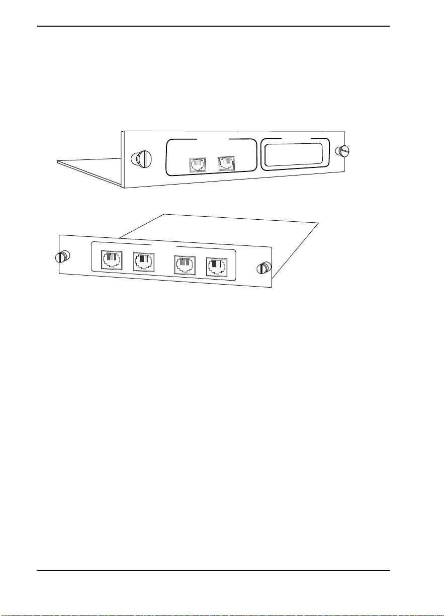
PHYSICAL DESCRIPTION
The FXS+ is an option module which plugs into the option
slot in the rear of the TSU 100. The plug-on module is placed
on top of a plug-in module. See Figure 1-1.
PORT X.3
PORT X.1
PORT X.2
QUAD FXS
PORT X.1
PORT X.3
DUAL FXS
PORT X.2
PORT X.4
HOT
REPLACEABLE
Figure 1-1. FXS+ Quad & Dual Voice Option Modules
The rear panel of the dual plug-in module includes a plastic
plug over a cutout for additional connectors. This allows a
plug-on board to be added to the FXS+ dual plug-in module.
The 1200302L1 (FXS+ Dual) voice module can accept any
plug-on module except the 1200082L1#HS. The FXS+ dual
plug-on can be placed on top of any option module that
accepts plug-ons.
PORT X.3
The
indication is linked to the port numbering
philosophy of the TSU 100 product family. The X represents
the slot number, and the
.3
indicates the port number. For the
TSU 100 application, there is only one option slot. Therefore
the port designations for the two plug-in FXS voice ports will
1.1
be
would be
and
1.2
. If added, the plug-on board port designation
1.3
and
1.4.
These port numbers will appear in the
front panel LCD menu displays. The remainder of the
manual will refer to port numbers as
1.1 or X.1
for
illustrative purposes.
1-4 FXS+ Quad & Dual Voice Option Module User Manual 61200300L1-1
Page 19

Chapter 2
Installation
UNPACK AND INSPECT
Carefully inspect the FXS+ Quad/Dual Voice option module
for any shipping damages. If damage is suspected, file a
claim immediately with the carrier and then contact
ADTRAN Customer and Product Service (CAPS). (See the
last page of this manual.) If possible, keep the original
shipping container for use in shipping the FXS+ module back
for repair or for verification of damage during shipment.
Items Shipped by ADTRAN
• FXS+ Quad/Dual Voice option module
• FXS+ Quad/Dual Voice Option Module User Manual (to
be inserted into main TSU 100/120/600 manual)
Items Provided by Customer
• Cable to connect the unit to the station.
61200300L1-1 FXS+ Quad & Dual Voice Option Module User Manual 2-1
Page 20

Chapter 2. Installation
INSTALLING THE FXS+ VOICE OPTION MODULE
Determine Revision Level of TSU 100/120/600
All TSU chassis support the FXS+ Quad/Dual Voice option
modules. TSU 100 units must have Software Revision L or
later, and the TSU 600 (1200076L1 and 1200076L2) must have
Software Revision F or later. To determine the revision level,
do the following:
Step Action Result
1 Power on the TSU.
2 Using the front panel keypad, se-
lect
item 3)
3 From the Utility Menu, select item
Software Revision
If the card is to be installed in a TSU 100, 120 or 600 with an
earlier software revision, ADTRAN recommends that the
TSU first be upgraded to the most recent revision to ensure
proper operation with the FXS+.
UTIL
.
.
The Utility Menu disp lay s .
The unit displays the revision
of the operating software.
For assistance with software revision upgrades, please contact
ADTRAN Technical Support at 1-888-4ADTRAN.
For ease of replacement, power to the TSU 100/120/600 may
be On when installing or removing the FXS+ Quad and Dual
Voice option modules.
2-2 FXS+ Quad & Dual Voice Option Module User Manual 61200300L1-1
Page 21

Placement of the Option Module
Figure 2-1 shows the proper placement of the option module.
To install the option module, follow these steps:
Step Action
1 Remove cover plate from the TSU 100/120/600 rear
panel.
2 Slide option module into the rear panel until it is posi-
tioned firmly against the front of the TSU 100/120/600
unit.
3 Fasten thumbscrews at both edges of the option mod-
ule.
Chapter 2. Installation
Cover Plate
TSU 100/120/600
Option Module
Figure 2-1. In st all i ng Op t io n Module
Power Connection
Each FXS+ module derives power from the base TSU 100/
120/600 unit. Power to the TSU 100/120/600 is supplied by a
captive eight-foot power cord.
61200300L1-1 FXS+ Quad & Dual Voice Option Module User Manual 2-3
Page 22

Chapter 2. Installation
Wiring
The FXS+ Quad and Dual Voice option module analog voice
interface connectors are universal and accept either an RJ-45
(8-pin modular plug) or an RJ-11 (6-pin modular plug). The
pinout is shown in Ta b l e 2 - 1 .
The required wiring connection is:
Connector Type (USOC) - RJ-45
Part number - AMP # 555164-1
Table 2-1. 2-Wire Voice Pinout Connection
Pin Name Description
5 Tip Tip lead of 2-wire interface
4 Ring Ring lead of 2-wire interface
1,2,3,6,7,8 Unused -
Pins used to mate with FXS+ connector are as follows:
Connec t or Pin
RJ-11 Tip 4
Ring 3
RJ-45 Tip 5
Ring 4
2-4 FXS+ Quad & Dual Voice Option Module User Manual 61200300L1-1
Page 23

Chapter 2. Installation
POWER UP TESTING AND INITIALIZATION
The FXS+ option module executes an abbreviated self-test
during the power-up sequence, as described in the TSU 100/
120/600 manual. Any previously configured setting for the
FXS+ is restored automatically upon power up.
Successful Self-Test
The green
front panel, illuminates when a successful self-test is
completed and the configuration is successfully restored. See
the Front Panel Operation section in the TSU 100/120/600
User Manual.
Failed Self-Test
If the FXS+ module fails one or more of the self-tests, a
message displays in the LCD during power-up. See the TSU
100/120/600 User Manual for more information. Specific
failures of the FXS+ module are identified in Appendix A,
FXS+ Failure Messages.
Operatio n Al arm s
The red
panel illuminates when an alarm condition is detected.
OK LED
ALARM LED
, located with the module LEDs on the
with the module LEDs on the front
61200300L1-1 FXS+ Quad & Dual Voice Option Module User Manual 2-5
Page 24

Chapter 2. Installation
Configuration of TX Level (TLP)
For any installation where the analog channel (DS0)
terminates within the Public Switched Telephone Network,
the TX LVL should be set to
applications where the channel terminates in other customer
equipment, any TX LVL may be used.
A+3 dB TLP setting attenuates the analog signal by 3 dB.
+3 dB
. For point-to-point
2-6 FXS+ Quad & Dual Voice Option Module User Manual 61200300L1-1
Page 25

Chapter 3
OVERVIEW
The FXS+ module is controlled as part of the TSU 100/120/
600 using the same methods described in the User Manual.
See the TSU 100/120/600 User Manual for descriptions of
front panel indicators and buttons.
Menu Structure
When an option module is installed in the TSU 100/120/600,
the unit adds it to the list of available options under the Port
menu items. These menu items are shown in Figure 3-1 on
page 3-2.
Menu Operation
An option module must be selected from a
before any of its menus are displayed.
Operatio n
ORT MENU
P
item
With the cursor on one of the Port menu items, press
display a list of the currently installed option modules.
To activate menus for the FXS+ option module, scroll through
the list to display
61200300L1-1 FXS+ Quad & Dual Voice Option Module User Manual 3-1
X.1 FXS+
and press
Enter
.
Enter
to
Page 26

Chapter 3. Operation
Once the option module is selected, the FXS+ menus appear
as a subset of, and operate the same as, menus for the TSU
100/120/600. With the cursor on one of the TSU 100/120/600
four main menu choices, press
or a
to
Enter
menu number
display the first two submenu items.
TSU 100
MAIN MENU
Use the
item and press
up and down arro ws
Enter
to display the first two submenu
to place the cursor on the desired
choices.
1) NI PERF REPORTS
1) STATUS 2) NI ERRORS
3) ACTIVE ALARMS
1) NETWORK (NI) 4) VIEW HISTORY
2) UNIT 5) PORT STATUS
2) CONFIG 3) MAP XCHANG 6) REMOTE PORT
4) MAP IN USE A(B) 7) CLEAR PORT ALM
5) DS0 MAP A
6) DS0 MAP B
7) PORT CONFIG 1) TIME/DATE
2) FACTORY RESTORE
3) SET PASSCODE
3) UTIL 4) UNIT ID
5) SOFTWARE REV
1) NETWORK TESTS 6) PORT UTILITY
4) TEST 2) RUN SELF-TEST
3) PORT TEST
4) CANCEL TEST
Figure 3-1. TSU Main Menu
Additional item menus may be displayed on the TSU 600/600e
products
3-2 FXS+ Quad & Dual Voice Option Module User Manual 61200300L1-1
Page 27

FXS+ Menu Item s
The FXS+ menus are accessed from, and operate the same as,
menus for the TSU 100/120/600. The FXS+ items are
submenu choices of the TSU 100/120/600 four main menus,
as shown in Figure 3-1. For information on
Run Self-Test
and
on page 3-17.
The FXS+ menu items are discussed in the following pages.
These items are:
•Port Status
• Port Configuration
• Port Utility
• Port Test
Port S tatu s
Port Status, a submenu of TSU 100/120/600 Main menu item
Status, displays active status information about the FXS+
interface.
Chapter 3. Operation
Factory Restore
, see TSU Features Used With FXS+ Options
Port Status
When
Enter
to display the first available port. See Figure 3-2. Scroll
to select
1.1 FXS+
displays, place the cursor on it and press
and press
Enter
to activate one of the
following submenus.
• 2W STATUS (2-wire status)
• VIEW SIG BITS (View Signalling Bits)
• SLC96 STATUS (2-wire status when SINGLE or UVG
modes)
61200300L1-1 FXS+ Quad & Dual Voice Option Module User Manual 3-3
Page 28

1) NI PERF REPORTS
1) STATUS
2) NI ERRORS
3) ACTIVE ALARMS
4) VIEW HISTORY
5) PORT STATUS 1.1 FXS+ 2W STATUS
6) REMOTE PORT
7) CLEAR PORT ALM
2W ST ATUS (2-Wire Status)
Chapter 3. Operation
VIEW SIG BITS
SLC96 STATUS
Figure 3-2. Port Status Submenus
Contains two information fields,
Busy
and
Ringing
, as
shown in Figure 3-3. An asterisk (*) indicates an item is active.
Figure 3-3. 2-Wire Status Display
Busy
An asterisk is present if loop current is flowing
through the 2-wire circuit.
Ringing
An asterisk is present if ringing voltage is being applied to the 2-wire circuit from the ring-generator
on the FXS+ option module
3-4 FXS+ Quad & Dual Voice Option Module User Manual 61200300L1-1
Page 29

Chapter 3. Operation
VIEW SIG BITS (View Signalling Bits)
VIEW SIG BITS
Use
to view the status of the RX and TX
signalling bits in the DS-1 stream. See Figure 3-4. If you are
operating in a SLC96 mode,
1/0
may be displayed. This
means that the signalling bit is toggling in each successive
frame for that port.
Figure 3-4. View Signalling Bits Display
SLC96 STATUS (Single and UVG Status)
SLC96 Status
channel basis related to the
and the
Customer (2W Ports)
is used to view the signalling states on a per-
Channel (Network Interface)
. The states are shown in
lexical representation to aid in determining system status
without monitoring and translating the signalling bits (
SIG BITS
UVG
or
SLC96 STATUS
).
is only available when
modes of operation are selected. See Figure 3-5.
VIEW
SINGL E
Figure 3-5. SLC96 Status Display
61200300L1-1 FXS+ Quad & Dual Voice Option Module User Manual 3-5
Page 30

PORT CONFIG (Port Configuration)
Chapter 3. Operation
Port Configuration
menu item
Configuration
, a submenu of TSU 100/120/600 main
, is used to configure the FXS+
option module. The following submenu items are used to
configure the parameters:
•MODE
• RX LVL (TLP)
•TX LVL (TLP)
• FAULT RESP
•ANSWER S’VSN
• TANDM OPTIONS
Supervision
-
Dial Tone
-
Loop Rev Bat
-
Ringback
-
DNIS Delay
-
DNIS Wink Timeout
-
Port Configuration
When
Enter
and press
to activate. Scroll to display the port to be
configured and press
displays, place the cursor on it
Enter
. See Figure 3-6.
The unit displays the first of five submenu items. Ta b l e 3 - 1 on
page 3-13 identifies the available selections for
Configuration
. Continue with standard operating
Port
procedure.
2) CONFIG
7) PORT CONFIG 2) RX LVL (TLP)
1.2 FXS+ 3) TX LVL (TLP)
1) MODE
4) FAULT RESP
5) ANSWER S’VSN
6) TANDM OPTIONS
Figure 3-6. Port Co nfi guration Sub m e nus
3-6 FXS+ Quad & Dual Voice Option Module User Manual 61200300L1-1
Page 31

MODE
Chapter 3. Operation
Mode
sets the type of 2-wire to T1 signalling and supervision
to be used. Choices include:
FXS_LS
This mode sets the port to use FXS loop-start signalling on
the T-Span and loop-start supervision on the analog 2-wire
interface.
It also supports far-end disconnect by removing tip-ground
during the call if signalled to do so over the T-Span. When
used with an ADTRAN FXO+, this feature allows linecurrent dropouts to be passed on to equipment connected to
the FXS+ 2-wire port.
Line Side Answer Supervision (LSAS) reverses Tip and Ring
polarity when a call originated from the FXS+ is answered.
To use this feature,
ANSWER S’VSN
must be enabled and
the port must receive Reverse Loop Current Feed (RLCF)
signalling on the T-span. Ringing cadence will follow that
provided over the T-Span or detected by the FXO port at the
far-end.
FXS_GS
This mode sets the port to use FXS ground start supervision
on the analog 2-wire interface. Ground start operation is
often used with trunk interfaces to PBS and key systems to
prevent glare conditions. Ringing cadence will follow that
provided over the T-Span or detected by the FXO port at the
far-end. Line Side Answer Supervision is also supported.
TANDEM_L S
This mode sets the port to use E&M signalling on the T-Span
and loop-start supervision or on the analog 2-wire interface.
When using this mode, line-current dropout for 500 ms is
provided when a call terminates and the far-end hangs up.
This may be useful for voice-mail or modem systems that
need far-end disconnect supervision. This mode also requires
61200300L1-1 FXS+ Quad & Dual Voice Option Module User Manual 3-7
Page 32

Chapter 3. Operation
other options to be selected. These options are
on page 3-11,
on page 3-11,
DNIS Wink Timeo ut
and
Dial To ne
Ringback
on page 3-11
on page 3-11
on page 3-12 .
Ringing cadence for incoming calls is
seconds off
.
, Loop Reverse Battery
, DNIS Delay
two seconds on, four
Supervision
page 3-12
TANDEM_GS
This mode sets the port to use E&M signalling on the T-Span
and ground start supervision on the analog 2-wire interface.
Ground-start operation is often used with trunk interfaces to
PBX and key systems to prevent glare conditions.
Appropriate
as described for
TANDM OPTIONS
TANDEM_LS
must be chosen in this mode
.
The Loop Reverse Battery is not applicable in this mode.
Ringing cadence for incoming calls is
seconds off
.
two seconds on, four
PLAR
This mode sets the port to use PLAR signalling on the T-Span
and loop-start supervision on the analog 2-wire interface.
This mode is used to provide a point-to-point hot line so that
when one telephone is lifted off-hook, the telephone at the
other end rings until it is also picked up.
When both ends are off-hook, a direct point-to-point
connection is established. Ringing cadence is
on, four seconds off
3-8 FXS+ Quad & Dual Voice Option Module User Manual 61200300L1-1
.
two seconds
Page 33

Chapter 3. Operation
SINGLE-SLC96
This mode sets the port to use Single Party channel unit
signalling on the T-Span (as defined by TR-TSY-000008) and
Loop Start supervision on the analog 2-wire interface. This
mode is used in a Digital Loop Carrier configuration when
the TSU/FXS+ combination acts as the Remote Terminal.
Channel Test signalling is ignored and the Forward
Disconnect feature is implemented by removing tip-ground
during the call. Line Side Answer Supervision is also
supported.
UVG-SLC96
This mode of operation will configure the port to use
Universal Voice Grade signalling on the T-span (as defined
by TR-TSY-000008) and either Loop Start or Ground Start
Supervision on the analog 2-wire interface. LSAS is
supported. The supervision on the 2-wire interface is
determined by the provisioning on the far side.
If... Then...
the signalling for the T-Span
is set for UVG (Loop Start) at
the FXS+ will have Loop Start supervision on the 2-wire interface.
the Digital Switch...
the signalling for the T-Span
is set for UVG (Ground Start)
at the Digital Switch...
the FXS+ will have Ground Start
supervision on the 2-wire interface.
No other settings are necessary to configure the supervision,
as the far-end determines it. Channel Test signalling is
ignored.
61200300L1-1 FXS+ Quad & Dual Voice Option Module User Manual 3-9
Page 34

RX LVL (TLP) (Receive Level/Transmit Level Point)
Chapter 3. Operation
RX LVL (TLP)
sets the RX direction transmission level points
(TLP). The TLP is indicated in dB and the relative loudness is
indicated by a bar graph display. Settings change
immediately as the bar graph is scrolled.
Choice range: -8 dB to 0 dB, in 1 dB steps
TX LVL (TLP) (Transmit Level/Transmit Level Point)
TX LVL (TLP)
sets the TX direction transmission level points
(TLP). The TLP is indicated in dB and the relative loudness is
indicated by a bar graph display. Settings change
immediately as the bar graph is scrolled.
Choice range: +3 dB to -5 dB, in 1 dB steps
FAULT RESP (Fault Response)
FAULT RESP
is used to set the 2-wire response to a carrier
alarm. For a network alarm, the ground start 2-wire trunk
would appear busy if
normal
, no seizure of a ground start trunk occurs.
Fault Resp
is set to
Choices: Normal, Seized
ANSWER S’VSN (Line Side Answer Supervision)
seized
. If set to
ANSWER S’VSN
far end (NI) has gone
OFFHOOK
, the FXS+ reverses polarity on the 2W interface.
is used to signal the 2W interface when the
OFFHOOK
. When the far end is
This option is valid for all modes of operation except PLAR.
Enabling
the 2W when receiving a wink in
LOOP REV BAT
ANSWER S’VSN
will not cause polarity reversal on
setting to respond to a wink.
TANDEM
modes. Use the
Choices: Enable, Disabled
3-10 FXS+ Quad & Dual Voice Option Module User Manual 61200300L1-1
Page 35

TANDM OPTIONS (Tandem Options)
Some options are valid only when operating in the tandem
mode. These options are provided below.
SUPERVISION
Chapter 3. Operation
Supervision
sets the supervision method used when the
card is configured to operate in the Tandem mode.
Choices: Immediate, Wink
DIALTONE
DIALTONE
is used to enable or disable the on-board dialtone generation when the FXS+ is operating in the tandem
mode. When the on-board dial-tone generation is enabled,
the dial-tone will turn off after a five second time-out.
Choices: Enabled, Disabled
LOOP REV BAT (Loop Reverse Battery)
TANDEM _ LS
In
polarity when
mode, this option reverses Tip and Ring
OFFHOOK
is received from the far-end. Loop
Reverse Battery responds to WINKS and OFFHOOK signals.
Use ANSWER S’VSN to respond only to the far-end going
OFFHOOK. Loop Reverse Battery is used to emulate DPO
functionality.
Choices: Enabled, Disabled
RINGBACK
This option generates ringback tone towards the T-Span
when enabled and the FXS+ card is in one of the tandem
modes. This may be needed in cases where the network does
not provide ringback tone.
Choices: Enabled, Disabled
61200300L1-1 FXS+ Quad & Dual Voice Option Module User Manual 3-11
Page 36

Chapter 3. Operation
DNIS DELAY
The option allows the FXS+ to be used in applications such as
automatic voice mail or paging systems with telephone
interfaces for POTS lines, which need to receive routing
information supplied from the Central Office (CO).
The FXS+ is placed in
TANDEM_LS
TANDEM_GS
or
mode
as required by the Customer Premises Equipment (CPE).
Supervision must be set to
WINK
mode. Signalling
conversion between the DID protocol expected by the CO
and POTS signalling on the 2-wire interface is made by the
FXS+.
After the CO seizes the trunk, the FXS+ waits for the CPE to
go off-hook and then sends a wink. After the wink, the FXS+
waits for the amount of time set by DNIS delay, then sends
answer supervision toward the CO.
The CPE must be able to answer calls within a carrierspecified time (usually 5 seconds), receive digits immediately
on answer, and route calls to their destinations within the
time set by DNIS delay.
Choices: Disabled, 0.5 sec, 1.0 sec., 1.5 sec. 2.0 sec., 2.5 sec., 3.0
sec., and 5.0 sec.
DNIS WINK T/O (DNIS Wink Timeout)
When
DNIS DELAY
DNIS WINK T/O
and
are both enabled,
the FXS+ option module winks to Telco if the equipment
connected to the 2W does not answer within 5 seconds to an
incoming call. The wink timeout feature ensures that Telco
will always see a response from the CPE, even if there is no
answer. If this option is left disabled, the FXS+ option module
will not wink until the incoming call is answered.
Choices: Enabled, Disabled
3-12 FXS+ Quad & Dual Voice Option Module User Manual 61200300L1-1
Page 37

Chapter 3. Operation
Port Configuration Menu Items/Parameters Summary
Table 3-1 provides a summary of the Port Configuration
menu items and their parameters.
T able 3-1. Port Configuration Parameters
Menu Item Parameter Choices
MODE *FXS_LS, FXS_GS, TANDEM_LS,
TAN D EM_GS, PLAR, SI NGLE-SLC96,
UVG-SLC96
RX LVL (TLP) -8 dB to 0 dB, 1 dB steps *(-6dB)
TX LVL (TLP) +3 dB to -5 dB, 1 DB steps *(+1 dB)
FAULT RESP *Normal, Seized
ANSWER S’VSN *Disabled, Enabled
SUPERVISION *I m mediat e, Wink
DIAL TONE *Disabled, Enabled
LOOP REV BAT *Disabled, Enabled
RINGBACK *Disabled, En abled
DNIS DELAY *Disabled, 0.5 to 5 seconds
DNIS WINK T/O *Disabled, Enabled
*Factory Default
61200300L1-1 FXS+ Quad & Dual Voice Option Module User Manual 3-13
Page 38

PORT UTIL (Port Utility)
Chapter 3. Operation
Port Utility
item
, a submenu of the TSU 100/120/600 Main menu
Utilities (UT IL)
, displays the current software
information for each port installed in the unit. This
information is required when requesting assistance from
ADTRAN Customer and Product Service or when updates
are needed.
Port Utility
When
Enter
to display the first available port. See Figure 3-7.
1) TIME/DATE
2) FACTORY RESTORE
3) SET PASSCODE
3) UTIL 4) UNIT ID
5) SOFTWARE REV
6)
displays, place the cursor on it and press
PORT UTILITY 1.1 FXS+ 1) SW REVISION
2) COMMAND MODE
Figure 3-7. Port Utility Submenus
Display
Enter
1.1 FXS+
(scroll to display if necessary), and press
. The unit displays the option module name and the
software version installed.
Port Utility
The
Command Mode
submenu contains a second option,
, for the FXS+ module. This option is
reserved for factory use only.
Cancel
Press
3-14 FXS+ Quad & Dual Voice Option Module User Manual 61200300L1-1
to exit or to select another port.
Page 39

Port Test
Chapter 3. Operation
Port Test
item
, a submenu of the TSU 100/120/600 Main menu
Test
, activates tests of the selected data ports. Selecting
the FSX+ displays tests available for this option module. See
Figure 3-8, below and Table 3-2 page 3-16.
1) NETWORK TESTS
4) TEST 2) RUN SELF-TEST
3) PORT TEST 1.1 FXS+ 3) SET TX SIGNAL
4) CANCEL TEST
1) 1KHZ TONE
2) VIEW SIG BITS
4) SET 2W OUTPUT
Figure 3-8. Port Test S ubm enus
Port Test
When
Enter
to display the first available port. Scroll to select
FXS+
and press
displays, place the cursor on it and press
1.1
Enter
to activate the following submenu
items:
•1 KHZ TONE
•VIEW SIG BITS
•SET TX SIGNAL
•SET 2W OUTPUT
These items are discussed on the following pages.
1 KHZ T ONE
KHZ SINE WAVE
This test injects a
1
either toward the far-end
(TX direction toward the T1 network) or toward the near-end
(the 2-wire interface on the option module). This tone may be
KHZ
used for testing or relative level measurements. When
TONE
is enabled, ringing and dial-tone for other channels on
1
the slot are suspended.
Choices: Off, Near, Far
61200300L1-1 FXS+ Quad & Dual Voice Option Module User Manual 3-15
Page 40

VIEW SIG BITS (View Signalling Bits)
Chapter 3. Operation
VIEW SIG BITS
is used to view the status of the RX and TX
signalling bits in the DS-1 stream. See Figure 3-9. If you are
operating in a SLC96 mode,
means that the signalling bit is toggling in each successive
frame for that port. The status of both the A and B bits is
displayed.
Figure 3-9. View Signalling Bits Display
SET TX SIGNAL (Set Transmit Signal)
SET TX SIGNAL
allows the
direction to be forced to a desired state for test.
SET 2W OUTPUT (Set 2-Wire Output)
1/0
may be displayed. This
A and B signal bits
in the TX
SET 2W OUTP UT
allows the 2-wire voice interface output to
be forced to a desired state for test.
Table 3-2. Port Test Parameters
Menu Item Parameter Choices
1 KHZ TONE Off, Near, Far
VIEW SIG BITS Display only
SET TX SIGNAL Off, (A=0, B=0), (A=0, B=1),
(A=1, B=0), (A=1, B=1)
SET 2W OUTPUT Off, Disabled, Tip Open, Active, Re-
verse Battery, Ringing
3-16 FXS+ Quad & Dual Voice Option Module User Manual 61200300L1-1
Page 41

TSU Fea tures Used With FXS+ Options
In addition to the FXS+ menu items, two additional menu
items of the TSU 100/120/600 may be operated in
conjunction with the FXS+ option module. These are
FACTORY RESTORE
FACTO RY RESTORE
RUN SELF-TEST
and
Chapter 3. Operation
.
RUN SELF-TEST
FACTORY RESTORE
Main menu item
, a submenu of the TSU 100/120/600
Utilit ies (U T I L )
, restores the factory
installed default setting for all FXS+ option module
parameters.
FACTORY RESTORE
When
and press
Enter
. The unit is restored to preset factory defaults
displays, place the cursor on it
and returns to the main TSU 100/120/600 menu. The factory
default for port configuration parameters in shown in Table
3-1 on page 3-13.
RUN SELF-TEST
menu item
, a submenu of the TSU 100/120/600 Main
TEST
, executes both the FXS+ internal test and
the TSU 100/120/600 internal test. The results of the self-test
are displayed in the LCD. See the TSU 100/120/600 User
Manual for additional information on
RUN SELF-TEST
When
press
Enter
to execute the test. The unit continuously changes
displays, place the cursor on it and
Self-Test
.
the display in the LCD window until all test results are
shown.
61200300L1-1 FXS+ Quad & Dual Voice Option Module User Manual 3-17
Page 42

Chapter 3. Operation
3-18 FXS+ Quad & Dual Voice Option Module User Manual 61200300L1-1
Page 43

Appendix A
FXS+ Failure Messages
FAILURE MESSAGES AT POWER-UP
The following messages indicate a probable component
failure on the FXS+ Module:
Table A-1. Failure Messages at Power-Up
E01 - EPROM CS EPROM checksum error
E02 - RAM ERR Static RAM error
E03 - OFF-HOOK Could not detect loop closure
E04 - RING GND Could not detect ring ground
E05 - RINGING Could not detect ring trip
E10 - SIGNALING Failure of signal bit transmission
FXS+ Alarm Messages
No alarms are specified for the FXS+ Voice option module.
61200300L1-1 FXS+ Quad and Dual Voice Option Module User Manual A-1
Page 44

Appendix A. FXS+ Failure Messages
A-2 FXS+ Quad and Dual Voice Option Module User Manual 61200300L1-1
Page 45

Appendix B
Signall ing States
SIGNALLING STATES VS. MODE OF OPERATION
The tables in this appendix describe the signalling states for
voice card and the DS-1 PCM stream. Ground start signalling
is not used in PLAR mode. See Table B-1.
Table B-1. PLAR Mode
FXS+
2W Input RX A RX B TX A TX B
Loop Open X X 1 1 _
Loop Closed X X 0 0 _
Loop Open 1 1 1 1 No Ringing
Loop Open 0 X 1 1 Ringing
Loop Closed 0 X 0 0 No Ringing
The A and B signal bit states on the DS-1 signal are as
follows:
Signal Means
0 logi c 0 is t he DS-1 str eam
1 logic 1 is the DS-1 stream
X value is not si gnificant
Loop Open phone on- hook
Loop Closed phone off-hook
FXS+
2W Output
61200300L1-1 FXS+ Quad and Dual Voice Option Module User Manual B-1
Page 46

Appen dix B. Signalling States
Ground start signalling provides its own tip ground in
response to ring ground in the Tandem Mode. See Table B-2.
Table B-2. Tandem Modes
FXS+
2W Input RX A RX B TX A TX B
(Outgoing call from FXS+1)
Loop Open 0 X 0 0 _ Idle
Loop Closed 0 X 1 1 _ Idle
Loop Closed 1 X 1 1 Dial Tone Wink
Loop Closed 0 X 1 1 _ Wink Done
Loop Closed 1 X 1 1 _ Answer Far End
(Incoming call to FXS+)
Loop Open 0 X 0 0 Idle
Loop Closed 1 X 0 0 Ringing Far end off hook
Loop Closed 1 X 1 1 Answers Far end off hook
FXS+
2W Output
Switch to FXS+
Condition
The A and B signal bit states on the DS-1 signal are as
follows:
Signal Means
0 logic 0 is the DS-1 stre am
1 logic 1 is the DS-1 stream
X value is not signi ficant
Loop Open phone on-hook
Loop Closed phone off-hook
B-2 FXS+ Quad and Dual Voice Option Module User Manual 61200300L1-1
Page 47

Appen dix B. Signalling States
Tables B-3 and B-4 describe FXS mode for signalling states.
Table B-3. FXS+ Mode (Loop-S tart)
FXS+
2W Input RX A RX B TX A TX B
(Outgoing call from FXS+)
Loop Open X 1 0 1 No Ringing (Idle)
Loop Closed X 1 1 1 No Ringing
Loop Closed X 1/0 1 1 Reverse Batter y
(Incoming call to FXS+)
Loop Open X 0 0 1 Ringing
Loop Closed X 0 1 1 No Ringing
FXS+
2W Output
The A and B signal bit states on the DS-1 signal are as
follows:
Signal Means
0 logic 0 is the DS-1 stream
1 logic 1 is the DS-1 stream
1/0 logic 1 followed by a logic 0 in
each successive sig nalling frame.
X value is not significant
Loop Open phone on-hook
Loop Closed phone off-hook
61200300L1-1 FXS+ Quad and Dual Voice Option Module User Manual B-3
Page 48

Appen dix B. Signalling States
Table B-4. FXS+ Mode (Ground Start)
FXS+
2W Input RX A RX B TX A TX B
(Outgoing call from FXS+1)
No Ring Gnd
or Loop Open
Ring Gnd 1 1 0 0 No Tip Gnd
Ring Gnd or
Loop Closed 0 1 1 1 Tip Gnd
Loop Closed 0 1 /0 0 1 Reverse Battery
Loop Open 0 1 0 1 Tip Gnd
Loop Open 1 1 0 1 Idle
(Incoming call to FXS+)
(Idle) 1 X - - No Tip Gnd & No Ringi ng
Loop Open 0 1 0 1 Tip Gnd & Ringing
Loop Closed 0 0 1 1 Tip Gnd & No Ringing
1101Idle
0 1 - - Tip Gnd & No Ringing
FXS+
2W Output
The A and B signal bit states on the DS-1 signal are as
follows:
Signal Means
0 logic 0 is the DS-1 stream
1 logic 1 is the DS-1 strea m
1/0 logic 1 followed by l ogic 0 in each
successive signalling frame
X value is not significant
Loop Open phone on-hook
Loop Closed phone off-hook
B-4 FXS+ Quad and Dual Voice Option Module User Manual 61200300L1-1
Page 49

Appen dix B. Signalling States
Table B-5. Single Mode
FXS+
2W Input RX A RX B TX A TX B
(Outgoing call from FXS+)
Loop Open X 1 0 0 No Ringing (Idle)
Loop Closed X 1 1 0 No Ringing
Loop Closed 1/0 1/0 1 0 Reverse Battery
(Incoming call to FXS+)
Loop Open X 1 0 0 No Ringing (Idle)
Loop Open X 1/0 0 0 Ringi ng
Loop Closed X 1 1 0 No Ringing
FXS+
2W Output
The A and B signal bit states on the DS-1 signal are as
follows:
Signal Means
0 logic 0 is the DS-1 stream
1 logic 1 is the DS-1 stream
1/0 logic 1 followed by logic 0 in each
successi ve signalling frame
X value is not significant
Loop Open phone on-hook
Loop Closed phone off-hook
61200300L1-1 FXS+ Quad and Dual Voice Option Module User Manual B-5
Page 50

Appen dix B. Signalling States
Table B-6. UVG Mode: Loop Start Provisioning on T-Span
FXS+
2W Input RX A RX B TX A TX B
(Outgoing call fro m FXS)
Loop Open X 1/0 0 0 No Ringing (Idle)
Loop Closed X 1/0 1 0 No Ringing
Loop Closed 1/0 1/0 1 0 Reverse Battery
(Incoming call to FXS+)
Loop Open 0 1/0 0 0 No Ringing (Idle)
Loop Open 0 1/0 0 0 Ringing
Loop Closed 0 1/0 1 0 No Ringing
FXS+
2W Output
The A and B signal bit states on the DS-1 signal are as
follows:
Signal Means
0 logic 0 is the DS-1 strea m
1 logic 1 is the DS-1 strea m
1/0 logic 1 followed by logic 0 i n each succes-
sive signalling frame
X value is not significant
Loop Open phone on-hook
Loop Closed phone off-hook
B-6 FXS+ Quad and Dual Voice Option Module User Manual 61200300L1-1
Page 51

Appen dix B. Signalling States
Table B-7. UVG Mode: Ground Start Provisioning on T-Span
FXS+
2W Input RX A RX B TX A TX B
(Outgoing call from FXS+)
Loop Open 0 0 0 0 No Ringing (Ground Start)
Ring Ground 0 0 0 1 No Tip Ground
Loop Closed 0 1/0 1 0 Tip Ground
Loop Closed 1/0 1/0 1 0 Reverse Battery
(Incoming call to FXS+)
Ground Start 0 0 0 0 No Ringing
Loop Open 1 1/0 0 0 Tip Ground & Ringing
Loop Open 0 1/0 0 0 Tip Ground & No Ringing
Loop Closed 0 1/0 1 0 Tip Ground & No Ringing
FXS+
2W Output
The A and B signal bit states on the DS-1 signal are as
follows:
Signal Means
0 logic 0 is the DS-1 stream
1 logic 1 is the DS-1 stream
1/0 logic 1 followe d by l ogic 0 i n each suc ces-
sive signall ing frame
X value is not significant
Loop Open phone on-hook
Loop Closed phone off-hook
61200300L1-1 FXS+ Quad and Dual Voice Option Module User Manual B-7
Page 52

Appen dix B. Signalling States
B-8 FXS+ Quad and Dual Voice Option Module User Manual 61200300L1-1
Page 53

Inde x
Numerics
2W STATUS (2-Wire Status) 3-4
2-Wire ERL, specification
2-Wire impedance, specification
2-Wire SRL, specification
2-Wire Status Display
2-Wire Voice Pinout Connection
3-4
1-3
1-3
1-3
2-4
A
ADTRAN Technical Support 2-2
ADTRAN Web Site
ADTRAN Y2K Information
ANSWER S’VSN
ANSWER S’VSN, port config menu
item
3-13
iii
3-7, 3-10
iii
C
Configuration of TX Level (TLP) 2-6
Connector, specification
Customer Service
Customer Service, Warranty
vii
1-3
vii
D
Dial Tone, port config menu item 3-13
DIALTONE, tandem option
DNIS Delay, port config menu item
13
DNIS Delay, tandem option
DNIS WINK T/O
DNIS Wink T/O, port config menu
item
3-13
DNIS Wink Timeout
3-12
3-12
3-11
3-12
E
E-mail, for Y2K info iii
Extended Range, specification
F
Factory Restore, TSU feature used
with FXS+ options
Failure Messages at Power-Up
Fault Resp (Fault Response)
FAULT RESP, port config menu item
3-13
Faxback Document Line, Y2K
Features, for FSX+ option module
Federal Communications Commission Radio Frequency Interference
Statement
Frequency Response, specification
Functional Description, FXS+
FXS+ Alarm Messages
FXS+ connector pins
FXS+ Dual Voice option module, features
FXS+ Dual Voice option module,
specifications
FXS+ Menu Items
FXS+ module, overview
3-
FXS+ Option Module Specifications
1-3
FXS+ Options, features
FXS+ Quad and Dual Voice, overview
1-1
FXS+, description
FXS+, physical description
1-2
v
1-3
3-3
1-2
3-17
2-4
A-1
3-17
3-1
1-4
1-3
3-10
iii
1-2
A-1
1-2
1-3
61200300L1- 1 FXS+ Quad and Dual Voice Option Module User Manual Index-1
Page 54

Index
FXS+, used in tandem mode 1-1
FXS_GS
FXS_LS
3-7
3-7
I
installing option module, how to 2-3
Items Provided by Customer
2-1
L
Line Side Answer Supervision 1-3, 3-7
3-9
Line Side Answer Supervisor, ANSWER S’VSN
Longitudinal Bal, specification
Loop Current, specification
Loop Range, specification
Loop Rev Bat, port config menu item
13
loop reverse battery
Loop Reverse Battery, tandem option
3-11
LSAS, line side answer supervision
3-10
3-11
1-3
1-3
1-3
3-7
M
Menu Operation 3-1
Menu Structure, of FXS+ module
MODE, port config menu item
3-13
3-1
O
Operating Temperature, specification
1-3
Operation Alarms
option module, placement
2-5
2-3
P
Physical Description, of FXS+ modules
1-4
PLAR
3-8
PORT CONFIG (Port Configuration)
6
PORT CONFIG, menu tree
Port Configuration Menu Items/Parameters Summary
Port Configuration Submenus, menu
tree
3-6
Port Status
Port Status, menu tree
Port Test
Port Test Parameters
,
Port Test, menu tree
port utility menu tree
Power Connection
Power up testing
Power-Up, failure messages
Product Matrix
Product Matrix, Y2K information
3-
3-15
3-3
3-13
3-4
3-16
3-15
3-14
2-3
2-5
iii
R
rear panel , dual module 1-4
repair, and return information
Ring Generator, specification
Ringback, port config menu item
Ringback, tandem option
Run Self-Test, TSU feature used with
FXS+ options
Rx Idle Channel Noise, specification
3
RX LVL (TLP) (Receive Level/Transmit Level Point)
RX LVL (TLP), port config menu item
3-13
3-17
3-10
S
Safety Instructions vi
Self-test, failed
Self-Test, successful
SET 2-W OUTPUT (Set 2-Wire Output)
3-16
Set TX SIGNAL (Set Transmit Signal)
3-
2-5
2-5
3-6
3-11
A-1
1-3
vii
iii
3-13
1-
Index-2 FXS+ Quad and Dual Voice Option Module User Manual 612 00300L1-1
Page 55

Index
3-16
shipping damages, what to do
Signaling states vs. mode of operation
B-1
Single Party, supported by FXS+ option modules
SINGLE-SLC96
SLC96 STATUS (Single and UVG Status)
3-5
SLC96 Status, example
software revision upgrades, assistance with
Specifications, FXS+ Option Module
1-3
Supervision, port config menu
Supervision, tandem option
2-2
1-1
3-9
3-5
3-11
2-1
3-13
T
TANDEM_GS 3-8
TANDEM_LS
TANDEM_LS, loop reverse battery
11
Tandm options
Tests, specification
THL ERL, specification
THL SRL, specification
Tip and Ring polarity, FXS_LS
Transmission Levels, specification
3
TSU Main Menu
3-7
3-11
3-2
1-3
1-3
1-3
3-7
TSU Menu Tree
Tx Idle Channel Noise, specification
1-3
TX LVL (TLP) (Transmit Level/
Transmit Level Point
TX LVL (TLP), port config menu item
3-13
3-2
3-10
U
Universal Voice Grade 3-9
Unpack and inspect
UVG-SLC96
3-9
2-1
V
VIEW SIG BITS (View Signalling Bits)
3-5
VIEW SIG BITS (View signalling Bits)
3-16
View Signaling Bits Display
Voice Channels, specification
3-
W
Warranty and Customer Service vii
Wiring, connection for modules
Y
1-
Y2K Project Line iii
Y2K Readiness Disclosure
Y2K, Faxback Document Line
3-16
1-3
2-4
iii
iii
61200300L1-1 FXS+ Quad and Dual Voice Option Module User Manual Index-3
Page 56

Index
Index-4 FXS+ Quad and Dual Voice Option Module User Manual 612 00300L1-1
Page 57

Product Support Information
Presales Inquiries and Applications Suppo rt
Please contact your local distributor, ADTRAN Applications Engineering, or ADTRAN Sales:
Applications Engineering (800) 615-1176
Sales (800) 827-0807
Post-Sale Support
Please contact your local distributor first. If your local distributor cannot help, please contact ADTRAN Technical Support and have the unit
serial number available.
Technical Support (888) 4ADTRAN
Repair and R et urn
If ADTRAN Technical Support determines that a repair is needed, Technical Support will coordinate with the Customer and Product Service
(CAPS) department to issue an RMA number. For information regarding equipment currently in house or possible fees associated with repair,
contact CAPS directly at the following number:
CAPS Department (256) 963-8722
Identify the RMA number clearly on the package (below address), and
return to the following address:
ADTRAN Customer and Product Service
6767 Old Madison Pike
Progress Center
Building #6, Suite 690
Huntsville, AL 35807
RMA # _____________
Page 58

 Loading...