

Page 1
Total Access® Quad BNC Adapter Module
J
2
J
1
J
3
J
4
T
X
1
R
X
1
1181007L2
T
X
2
R
X
2
Installation and Maintenance
CONTENTS
1. GENERAL ............................................................1
2. FEATURES .......................................................... 1
3. INSTALLATION ................................................. 3
4. CONNECTIONS ..................................................3
5. MAINTENANCE .................................................3
6. PRODUCT SPECIFICATIONS ...........................4
7. WARRANTY AND CUSTOMER SERVICE .....4
FIGURES
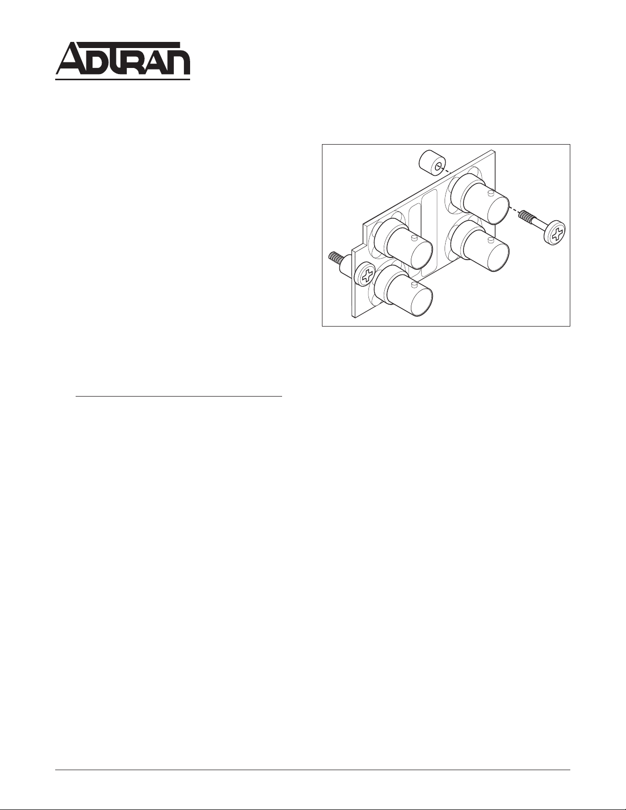
Figure 1. ADTRAN Total Access Quad BNC
Adapter Module .........................................1
Figure 2. Block Diagram of the Quad BNC Adapter
Module .......................................................2
Section 61181007L2-5A
Issue 1, February 2003
1. Proper receive termination for an EC-1 signal.
TABLES
Table 1. Quad BNC Adapter Module
Specifications .............................................4
1. GENERAL
This practice is an installation and maintenance guide
for the ADTRAN Total Access Quad BNC Adapter
Module illustrated in Figure 1. The 1181007L2 Quad
BNC Adapter Module is designed to mount on the
rear of the ADTRAN Total Access chassis,
P/N 1181001L1 (23-inch) or 1182003L1 (19-inch).
The Quad BNC Adapter Module provides Dual STS-1
interfaces for the Total Access 3000 and Total Access
3010 Chassis. The Quad BNC Adapter Module must
be used in conjunction with an OC-3 L2 MUX (P/N
1181031L2). It will also work in conjunction with
either the L1 or L2 versions of the STS-1 MUX (P/N
1181030L1/L2). For information on the OC-3 L2
MUX, refer to ADTRAN Document 61181031L2-5A.
Revision History
This is the initial issue of this practice. Future
revisions to this document will be explained in this
subsection.
Figure 1. ADTRAN Total Access Quad
BNC Adapter Module
2. FEATURES
The Quad BNC Adapter Module is designed to mount
on the lower right-hand corner of the backplane of a
Total Access 3000 or Total Access 3010 chassis. The
unit provides the coax cable connections for two Total
Access chassis which subtend from a Total Access
equipped with an OC-3 L2 MUX.
The Quad BNC Adapter Module for the Total Access
chassis provides a data path for two STS-1s from the
OC-3 equipment Total Access to the subtending Total
Access chassis.
The Quad BNC Adapter Module provides:
2. A means of interfacing the transmit EC-1 line
from either multiplexer module.
3. Four 75-ohm BNC connectors – two for
transmit data and two for receive data.
4. Connection to the Total Access backplane at
the 24-pin connector provided for that purpose
and attaches with screws to ensure rigidity.
61181007L2-5A 1
Trademarks: Any brand names and product names included in this document are
trademarks, registered trademarks, or trade names of their respective holders.
Page 2
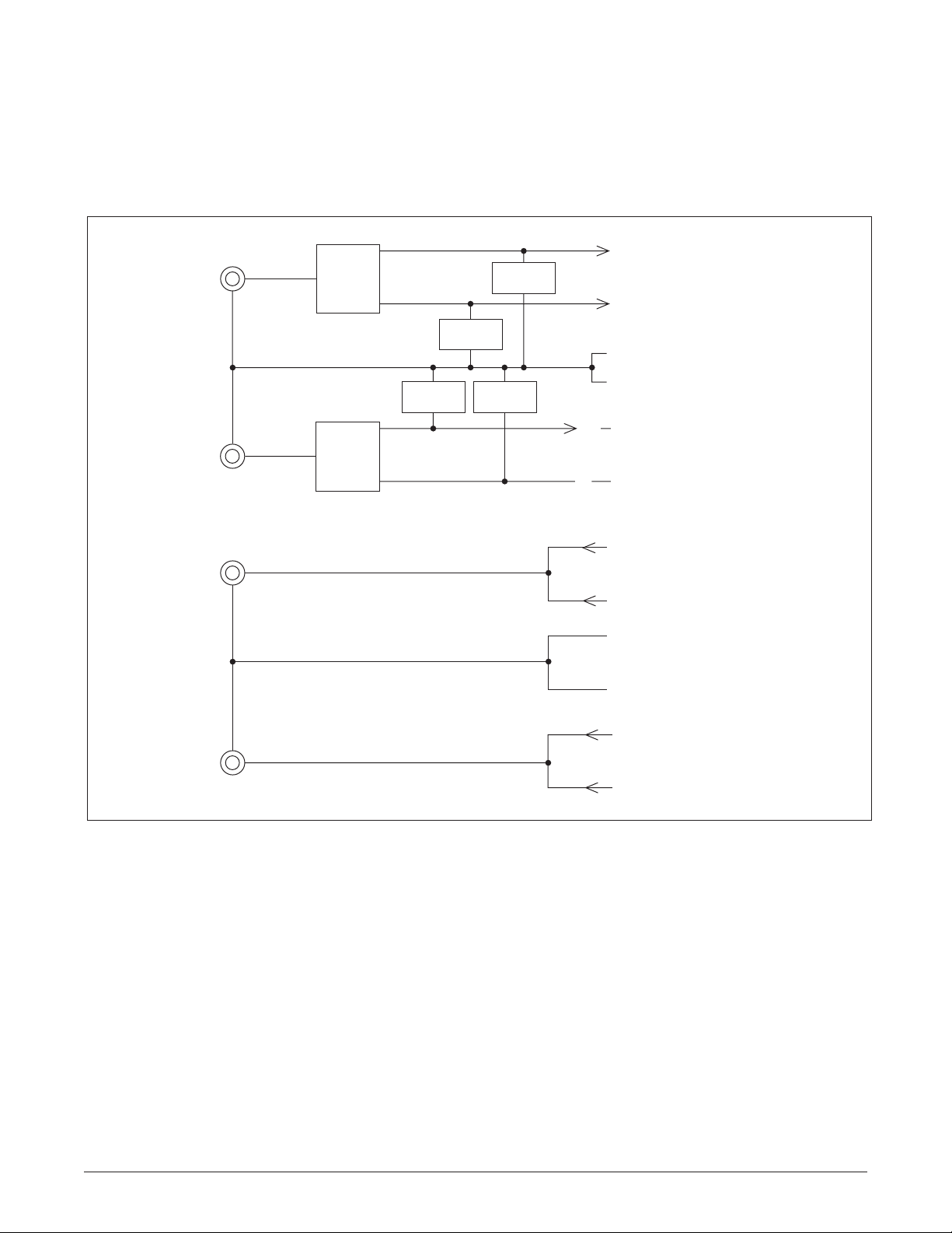
Figure 2 is a block diagram of the Quad BNC Adapter
Module for Total Access 3000 and Total Access 3010.
Receive (1)
Input
(BNC)
Receive (2)
Input
(BNC)
Transmit (1)
Output
(BNC)
Splitter
Splitter
R-Term
R-Term
R-Term
R-Term
Pin 1 RX to MUX A (EC-1 #1)
Pin 22 RX to MUX B (EC-1 #1)
Pins 2, 4, 5, 6 (A RX Gnd)
Pins 18, 19, 21 (B RX Gnd)
Pin 20 RX to MUX B (EC-1 #2)
20
Pin 3 RX to MUX A (EC-1 #2)
3
Pin 8 TX from MUX A (EC-1 #1)
Pin 15 TX from MUX B (EC-1 #1)
Pins 7, 9, 11, 12 (A TX Gnd)
Pins 14, 16, 17 (A TX Gnd)
Transmit (2)
Pin 10 TX from MUX A (EC-1 #2)
Output
(BNC)
Pin 13 TX from MUX B (EC-1 #2)
Figure 2. Block Diagram of the Quad BNC Adapter Module
2 61181007L2-5A
Page 3

C A U T I O N
3. INSTALLATION
C A U T I O N
SUBJECT TO ELECTROSTATIC DAMAGE
OR DECREASE IN RELIABILITY.
HANDLING PRECAUTIONS REQUIRED.
!
After unpacking the unit, inspect it for damage. If
damage is discovered, file a claim with the carrier,
then contact ADTRAN. Refer to Warranty and
Customer Service.
Two phillips-head captive screws are provided with
the Quad BNC Adapter Module. Use the screws and a
phillips screwdriver to attach the Quad BNC Adapter
Module to the back of the Total Access 3000 or Total
Access 3010 chassis with the screw spacer between
the Quad BNC Adapter and the chassis surface.
CAUTION
This module should never be installed while
power is present on the chassis. Doing so can
cause damage to the backplane during
installation.
4. CONNECTIONS
Coax cable is easily connected to the Quad BNC
Adapter Module. The RX connectors on the Quad
BNC Adapter Module connect to the two EC-1 signals
coming from the network. Similarly, the TX
connectors on the Quad BNC Adapter Module
connect to the two EC-1 signals going to the network.
To be UL 1950 certified, ADTRAN requires that the
following connection guidelines be observed:
• The Total Access chassis must be connected
to a reliably grounded -48 VDC source which
is electrically isolated from the AC source.
• The frame ground stud located on the chassis
must be connected to a reliable frame ground
source.
• A readily accessible disconnect device that is
suitably approved and rated must be
incorporated into the fixed power wiring
(e.g., Fuse and Alarm Panel).
• The branch circuit overcurrent protection
must be a properly sized fuse or circuit
breaker rated for −48 V.
To be UL 1950 certified, ADTRAN requires that these
installation guidelines be followed:
• The Quad BNC Adapter Module is intended
for installation in Restricted Access Locations
Only.
• The Quad BNC Adapter Module must be
installed in accordance with the requirements
of NEC NFPA 70.
5. MAINTENANCE
The ADTRAN Total Access Quad BNC Adapter
Module does not require any routine maintenance for
normal operation. ADTRAN cautions against
performing major repairs in the field. Repair services
may be obtained by returning the defective unit to
ADTRAN. (Refer to the Warranty and Customer
Service section of this practice.)
61181007L2-5A 3
Page 4

6. PRODUCT SPECIFICATIONS
Product specifications are detailed in Table 1.
Refer to the following subsections for sales, support,
CAPS requests, or further information.
7. WARRANTY AND CUSTOMER SERVICE
ADTRAN will replace or repair this product within
the warranty period if it does not meet its published
specifications or fails while in service. Warranty
information can be found at
www.adtran.com/warranty.
U.S. and Canada customers can also receive a copy of
the warranty via ADTRAN’s toll-free faxback server
at 877-457-5007.
• Request Document 414 for the U.S. and Canada
Carrier Networks Equipment Warranty.
• Request Document 901 for the U.S. and Canada
Enterprise Networks Equipment Warranty.
ADTRAN Sales
Pricing/Availability:
800-827-0807
ADTRAN Technical Support
Pre-Sales Applications/Post-Sales Technical Assistance:
800-726-8663
Standard hours: Monday - Friday, 7 a.m. - 7 p.m. CST
Emergency hours: 7 days/week, 24 hours/day
ADTRAN Repair/CAPS
Return for Repair/Upgrade:
(256) 963-8722
Repair and Return Address
Contact Customer and Product Service (CAPS) prior
to returning equipment to ADTRAN.
ADTRAN, Inc.
CAPS Department
901 Explorer Boulevard
Huntsville, Alabama 35806-2807
Table 1. Quad BNC Adapter Module Specifications
Size:
2.3 in. H x 1.4 in. W x 1.75 in. D
Conforms to Total Access 3000 and 3010 mechanical and pinout requirements
Connector:
24-pin low profile .050 in. centers male header with end shrouds and guideposts
Environmental:
-40ºC to +65ºC operational
-40ºC to +85ºC storage
Up to 95% noncondensing humidity
Regulatory Requirements:
NEBS Level 3
GR-1089-CORE
UL1950
4 61181007L2-5A
 Loading...