

Page 1
LPU
®
1181500L2
POWER
UNDER VOLTAGE
GROUND FAULT
OVERLOAD
UNDER CURRENT
Total Access 3000/3010
4-Pair Line Power Unit
Installation and Maintenance Practice
Document Number: 61181500L2-5B
CLEI: SIPQ0CTF_ _
April 2007
Page 2

Total Access 3000/3010 4-Pair Line Power Unit Installation and Maintenance Practice
Front Matter
Trademarks
Any brand names and product names included in this document are trademarks, registered
trademarks, or trade names of their respective holders.
To the Holder of this Document
The contents of this document are current as of the date of publication. ADTRAN® reserves the
right to change the contents without prior notice.
In no event will ADTRAN be liable for any special, incidental, or consequential damages or
for commercial losses even if ADTRAN has been advised thereof as a result of issue of this
document.
®
901 Explorer Boulevard
P.O. Box 140000
Huntsville, AL 35814-4000
(256) 963-8000
©2007 ADTRAN, Inc.
All Rights Reserved.
ii 61181500L2-5B
Page 3

Revision History
Revision Date Description
A August 2005 Initial Release
B April 2007 Second Issue. Updated product description.
Conventions
The following typographical conventions are used in this document:
This font indicates a cross-reference link.
This font indicates screen menus, fields, and parameters.
THIS FONT indicates keyboard keys (ENTER, ESC, ALT). Keys that are to be pressed simultaneously
are shown with a plus sign (
same time
).
This font indicates references to other documentation and is also used for emphasis.
This font indicates on-screen messages and prompts.
This font indicates text to be typed exactly as shown.
ALT+X indicates that the ALT key and X key should be pressed at the
This font indicates silk-screen labels or other system label items.
This font is used for strong emphasis.
NOTE
Notes inform the user of additional, but essential, information or
features.
CAUTION
Cautions inform the user of potential damage, malfunction, or
disruption to equipment, software, or environment.
WARNING
Warnings inform the user of potential bodily pain, injury, or death.
61181500L2-5B iii
Page 4

Total Access 3000/3010 4-Pair Line Power Unit Installation and Maintenance Practice
Training
ADTRAN offers training courses on our products. These courses include overviews on product
features and functions while covering applications of ADTRAN product lines. ADTRAN
provides a variety of training options, including customized training and courses taught at our
facilities or at customer sites.
For inquiries concerning training, contact ADTRAN:
Training Phone: 800-615-1176, ext. 6996
Training Fax: 256-963-6217
Training Email: training@adtran.com
iv 61181500L2-5B
Page 5

Contents
General . . . . . . . . . . . . . . . . . . . . . . . . . . . . . . . . . . . . . . . . . . . . . . . . . . . . . . . . . . . . . . . . . . . . . . . . . . . . . . . . . . 1
Description . . . . . . . . . . . . . . . . . . . . . . . . . . . . . . . . . . . . . . . . . . . . . . . . . . . . . . . . . . . . . . . . . . . . . . . . . . . . 2
Features . . . . . . . . . . . . . . . . . . . . . . . . . . . . . . . . . . . . . . . . . . . . . . . . . . . . . . . . . . . . . . . . . . . . . . . . . . . . . . 2
Compliance . . . . . . . . . . . . . . . . . . . . . . . . . . . . . . . . . . . . . . . . . . . . . . . . . . . . . . . . . . . . . . . . . . . . . . . . . . . . 3
Installation . . . . . . . . . . . . . . . . . . . . . . . . . . . . . . . . . . . . . . . . . . . . . . . . . . . . . . . . . . . . . . . . . . . . . . . . . . . . . . . 5
Installation Considerations . . . . . . . . . . . . . . . . . . . . . . . . . . . . . . . . . . . . . . . . . . . . . . . . . . . . . . . . . . . . . . . . 5
Shipping Contents . . . . . . . . . . . . . . . . . . . . . . . . . . . . . . . . . . . . . . . . . . . . . . . . . . . . . . . . . . . . . . . . . . . . . . 5
Instructions for Installing the Module . . . . . . . . . . . . . . . . . . . . . . . . . . . . . . . . . . . . . . . . . . . . . . . . . . . . . . . . 5
Wiring . . . . . . . . . . . . . . . . . . . . . . . . . . . . . . . . . . . . . . . . . . . . . . . . . . . . . . . . . . . . . . . . . . . . . . . . . . . . . . . . 7
Powering . . . . . . . . . . . . . . . . . . . . . . . . . . . . . . . . . . . . . . . . . . . . . . . . . . . . . . . . . . . . . . . . . . . . . . . . . . . . . . 8
Deployment Guidelines . . . . . . . . . . . . . . . . . . . . . . . . . . . . . . . . . . . . . . . . . . . . . . . . . . . . . . . . . . . . . . . . . . 9
Front Panel LEDs . . . . . . . . . . . . . . . . . . . . . . . . . . . . . . . . . . . . . . . . . . . . . . . . . . . . . . . . . . . . . . . . . . . . . . . 9
Alarms . . . . . . . . . . . . . . . . . . . . . . . . . . . . . . . . . . . . . . . . . . . . . . . . . . . . . . . . . . . . . . . . . . . . . . . . . . . . . . 10
System Management . . . . . . . . . . . . . . . . . . . . . . . . . . . . . . . . . . . . . . . . . . . . . . . . . . . . . . . . . . . . . . . . . . . . . . 11
Craft Interface . . . . . . . . . . . . . . . . . . . . . . . . . . . . . . . . . . . . . . . . . . . . . . . . . . . . . . . . . . . . . . . . . . . . . . . . . 11
Logging on to the Total Access 3000/3010 . . . . . . . . . . . . . . . . . . . . . . . . . . . . . . . . . . . . . . . . . . . . . . . . . . 12
User Interface . . . . . . . . . . . . . . . . . . . . . . . . . . . . . . . . . . . . . . . . . . . . . . . . . . . . . . . . . . . . . . . . . . . . . . . . . . . . 14
Menu Structure . . . . . . . . . . . . . . . . . . . . . . . . . . . . . . . . . . . . . . . . . . . . . . . . . . . . . . . . . . . . . . . . . . . . . . . . 14
Menus . . . . . . . . . . . . . . . . . . . . . . . . . . . . . . . . . . . . . . . . . . . . . . . . . . . . . . . . . . . . . . . . . . . . . . . . . . . 14
Screen . . . . . . . . . . . . . . . . . . . . . . . . . . . . . . . . . . . . . . . . . . . . . . . . . . . . . . . . . . . . . . . . . . . . . . . . . . . 14
Menu Navigation . . . . . . . . . . . . . . . . . . . . . . . . . . . . . . . . . . . . . . . . . . . . . . . . . . . . . . . . . . . . . . . . . . . . . . . 15
General Keyboard Commands . . . . . . . . . . . . . . . . . . . . . . . . . . . . . . . . . . . . . . . . . . . . . . . . . . . . . . . . . 15
Menu Tree . . . . . . . . . . . . . . . . . . . . . . . . . . . . . . . . . . . . . . . . . . . . . . . . . . . . . . . . . . . . . . . . . . . . . . . . . . . 15
Menu Descriptions. . . . . . . . . . . . . . . . . . . . . . . . . . . . . . . . . . . . . . . . . . . . . . . . . . . . . . . . . . . . . . . . . . . . . . . . 17
Configuration Screen . . . . . . . . . . . . . . . . . . . . . . . . . . . . . . . . . . . . . . . . . . . . . . . . . . . . . . . . . . . . . . . . . . . 18
Provisioning Menu . . . . . . . . . . . . . . . . . . . . . . . . . . . . . . . . . . . . . . . . . . . . . . . . . . . . . . . . . . . . . . . . . . . . . 19
Status Screen . . . . . . . . . . . . . . . . . . . . . . . . . . . . . . . . . . . . . . . . . . . . . . . . . . . . . . . . . . . . . . . . . . . . . . . . . 20
Alarms Screen . . . . . . . . . . . . . . . . . . . . . . . . . . . . . . . . . . . . . . . . . . . . . . . . . . . . . . . . . . . . . . . . . . . . . . . . 21
Software Download Menu . . . . . . . . . . . . . . . . . . . . . . . . . . . . . . . . . . . . . . . . . . . . . . . . . . . . . . . . . . . . . . . 22
Maintenance . . . . . . . . . . . . . . . . . . . . . . . . . . . . . . . . . . . . . . . . . . . . . . . . . . . . . . . . . . . . . . . . . . . . . . . . . . . . . 23
Specifications. . . . . . . . . . . . . . . . . . . . . . . . . . . . . . . . . . . . . . . . . . . . . . . . . . . . . . . . . . . . . . . . . . . . . . . . . . . . 23
61181500L2-5B v
Page 6

Total Access 3000/3010 4-Pair Line Power Unit Installation and Maintenance Practice
Appendix A
Warranty . . . . . . . . . . . . . . . . . . . . . . . . . . . . . . . . . . . . . . . . . . . . . . . . . . . . . . . . . . . . . . . . . . . . . . . A-1
Warranty and Customer Service . . . . . . . . . . . . . . . . . . . . . . . . . . . . . . . . . . . . . . . . . . . . . . . . . . . . . . . . A-1
ADTRAN Sales . . . . . . . . . . . . . . . . . . . . . . . . . . . . . . . . . . . . . . . . . . . . . . . . . . . . . . . . . . . . . . . . . . . A-1
ADTRAN Technical Support . . . . . . . . . . . . . . . . . . . . . . . . . . . . . . . . . . . . . . . . . . . . . . . . . . . . . . . . . A-1
ADTRAN Repair/CAPS . . . . . . . . . . . . . . . . . . . . . . . . . . . . . . . . . . . . . . . . . . . . . . . . . . . . . . . . . . . . . A-1
Repair and Return Address . . . . . . . . . . . . . . . . . . . . . . . . . . . . . . . . . . . . . . . . . . . . . . . . . . . . . . . . . . A-1
Figures
Figure 1. LPU Front Panel . . . . . . . . . . . . . . . . . . . . . . . . . . . . . . . . . . . . . . . . . . . . . . . . . . . . . . . . . . . . . . . . 1
Figure 2. Total Access System Logon Screen . . . . . . . . . . . . . . . . . . . . . . . . . . . . . . . . . . . . . . . . . . . . . . . 12
Figure 3. Total Access Main Menu . . . . . . . . . . . . . . . . . . . . . . . . . . . . . . . . . . . . . . . . . . . . . . . . . . . . . . . . 13
Figure 4. Access Modules Menus Menu . . . . . . . . . . . . . . . . . . . . . . . . . . . . . . . . . . . . . . . . . . . . . . . . . . . . 13
Figure 5. LPU Menu Tree . . . . . . . . . . . . . . . . . . . . . . . . . . . . . . . . . . . . . . . . . . . . . . . . . . . . . . . . . . . . . . . 16
Figure 6. LPU Main Menu . . . . . . . . . . . . . . . . . . . . . . . . . . . . . . . . . . . . . . . . . . . . . . . . . . . . . . . . . . . . . . . 17
Figure 7. Configuration Screen . . . . . . . . . . . . . . . . . . . . . . . . . . . . . . . . . . . . . . . . . . . . . . . . . . . . . . . . . . . 18
Figure 8. Provisioning Menu . . . . . . . . . . . . . . . . . . . . . . . . . . . . . . . . . . . . . . . . . . . . . . . . . . . . . . . . . . . . . 19
Figure 9. Status Screen . . . . . . . . . . . . . . . . . . . . . . . . . . . . . . . . . . . . . . . . . . . . . . . . . . . . . . . . . . . . . . . . . 20
Figure 10. Alarms Screen . . . . . . . . . . . . . . . . . . . . . . . . . . . . . . . . . . . . . . . . . . . . . . . . . . . . . . . . . . . . . . . . 21
Figure 11. Software Download Menu . . . . . . . . . . . . . . . . . . . . . . . . . . . . . . . . . . . . . . . . . . . . . . . . . . . . . . . 22
Tables
Table 1. Compliance Codes . . . . . . . . . . . . . . . . . . . . . . . . . . . . . . . . . . . . . . . . . . . . . . . . . . . . . . . . . . . . . . 3
Table 2. Wiring Example . . . . . . . . . . . . . . . . . . . . . . . . . . . . . . . . . . . . . . . . . . . . . . . . . . . . . . . . . . . . . . . . 7
Table 3. Span Powered Pair Assignments . . . . . . . . . . . . . . . . . . . . . . . . . . . . . . . . . . . . . . . . . . . . . . . . . . . 8
Table 4. Current and Voltage Limits . . . . . . . . . . . . . . . . . . . . . . . . . . . . . . . . . . . . . . . . . . . . . . . . . . . . . . . . 8
Table 5. Front Panel LEDs . . . . . . . . . . . . . . . . . . . . . . . . . . . . . . . . . . . . . . . . . . . . . . . . . . . . . . . . . . . . . . . 9
Table 6. Alarm Descriptions and Causes . . . . . . . . . . . . . . . . . . . . . . . . . . . . . . . . . . . . . . . . . . . . . . . . . . . 10
Table 7. General Keyboard Commands . . . . . . . . . . . . . . . . . . . . . . . . . . . . . . . . . . . . . . . . . . . . . . . . . . . . 15
Table 8. LPU Main Menu Options . . . . . . . . . . . . . . . . . . . . . . . . . . . . . . . . . . . . . . . . . . . . . . . . . . . . . . . . 17
Table 9. Configuration Screen Fields . . . . . . . . . . . . . . . . . . . . . . . . . . . . . . . . . . . . . . . . . . . . . . . . . . . . . . 18
Table 10. Provisioning Menu Options . . . . . . . . . . . . . . . . . . . . . . . . . . . . . . . . . . . . . . . . . . . . . . . . . . . . . . 19
Table 11. Status Screen Fields . . . . . . . . . . . . . . . . . . . . . . . . . . . . . . . . . . . . . . . . . . . . . . . . . . . . . . . . . . . 20
Table 12. Alarms Screen Fields . . . . . . . . . . . . . . . . . . . . . . . . . . . . . . . . . . . . . . . . . . . . . . . . . . . . . . . . . . . 21
Table 13. Software Download Menu Options . . . . . . . . . . . . . . . . . . . . . . . . . . . . . . . . . . . . . . . . . . . . . . . . . 22
Table 14. Specifications . . . . . . . . . . . . . . . . . . . . . . . . . . . . . . . . . . . . . . . . . . . . . . . . . . . . . . . . . . . . . . . . . 23
vi 61181500L2-5B
Page 7
Total Access 3000/3010
4-Pair Line Power Unit
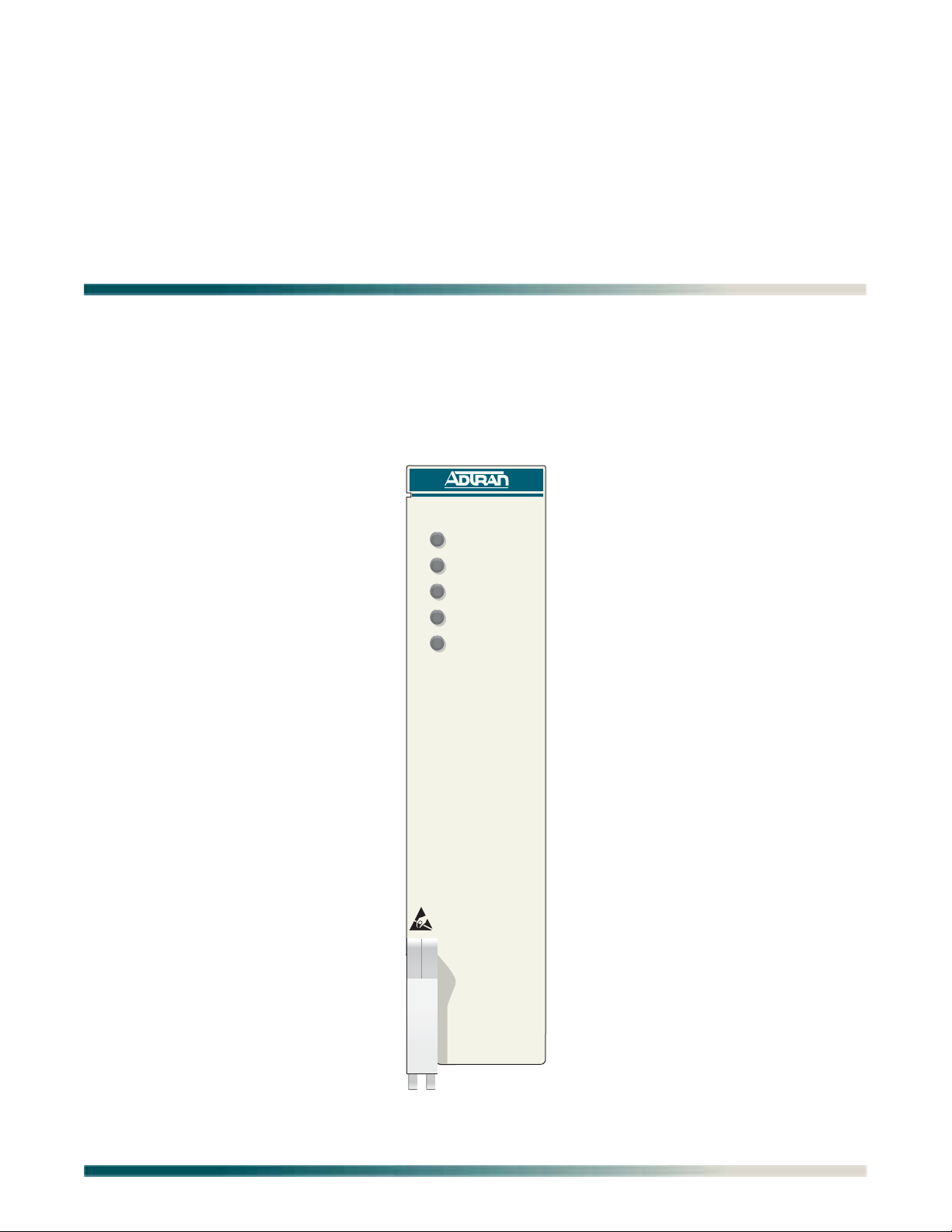
GENERAL
This practice is an installation and maintenance guide for the ADTRAN Total Access® 3000/
3010 4-Pair Line Power Unit (LPU). Figure 1 illustrates the LPU (P/N 1181500L2) front panel.
LPU
1181500L2
POWER
UNDER VOLTAGE
GROUND FAULT
OVERLOAD
UNDER CURRENT
Figure 1. LPU Front Panel
61181500L2-5B 1
Page 8

Total Access 3000/3010 4-Pair Line Power Unit Installation and Maintenance Practice
Description
The LPU is a span powering Total Access 3000/3010 module, which is used to supply 100
watts of DC power over multiple twisted pairs of various standard gauges to a Total Access
11xx OSP Digital Subscriber Line Access Multiplexer (DSLAM). The LPU can be installed
either at a Central Office (CO) or a remote facility in close proximity to the associated DSLAM.
The LPU provides ±145 VDC power and can span distances up to 60 kft (approximately 11
miles).
Features
The basic features of the LPU include the following:
• Provides 100 watts of power
• Provides power to remote DSLAMs for distances up to 60 kft
• Provides ±145 VDC power rails
• Provides powering over any combination of the four available pairs
• Provides alarms for Under Voltage, Ground Fault, Overload, and Under Current
• Provides five LEDs:
CURRENT
• LPU can be provisioned In Service, Out of Service-Maintenance, or Out of ServiceUnassigned.
• Meets Total Access 3000/3010 dual module form factor
• Provides SNMP management
• Provides TL1 Network Management Access alarm support
• Menu access via the Total Access 3000/3010 Controller Unit
• Application software can be upgraded in the field
• Meets all requirements over an ambient temperature range of –40ºC to +70ºC
POWER, UNDER VOLTAGE, GROUND FAULT, OVERLOAD, and UNDER
2 61181500L2-5B
Page 9

Compliance
C A U T I O N !
SUBJECT TO ELECTROSTATIC DAMAGE
OR DECREASE IN RELIABILITY.
HANDLING PRECAUTIONS REQUIRED.
The span voltages are up to ±145 VDC with respect to ground and
up to 290 VDC between the tip/ring pairs.
Electrostatic Discharge (ESD) can damage electronic modules.
When handling modules, wear an antistatic discharge wrist strap
to prevent damage to electronic components. Place modules in
antistatic packing material when transporting or storing. When
working on modules, always place them on an approved antistatic
mat that is electrically grounded.
General
WARNING
CAUTION
Table 1 lists the compliance codes for the LPU. The LPU is NRTL Listed to the applicable UL
standards. The LPU meets or exceeds all the applicable requirements of NEBS, Telcordia GR63-CORE, and GR-1089-CORE.
The LPU is intended for deployment in Central Office type facilities, EEEs and EECs. Install
the LPU in a Total Access 3000/3010 Chassis located in a restricted access location.
Table 1. Compliance Codes
Configuration Code Input Output
Power Code (PC) F C
Telecommunication Code (TC) – X
Installation Code (IC) A –
This device complies with Part 15 of the FCC rules. Operation is subject to the following two
conditions:
1. This device may not cause harmful interference
2. This device must accept any interference received, including interference that may cause
undesired operation.
Changes or modifications not expressly approved by ADTRAN could void the user’s authority
to operate this equipment.
61181500L2-5B 3
Page 10

Total Access 3000/3010 4-Pair Line Power Unit Installation and Maintenance Practice
CAUTION
Per GR-1089-CORE the Total Access 3000/3010 System is
designed and intended for installation as part of a Common
Bonding Network (CBN). The Total Access 3000/3010 System is
not designed nor intended for installation as part of an Isolated
Bonding Network (IBN).
CAUTION
Per GR-1089-CORE Section 9, the LPU does not have an internal
DC connection between –48 VR and frame ground. The LPU can be
installed in a DC-I (isolated) or DC-C (common) installation. For
installations where other cards or the host system have internal
connections between –48 VR and frame ground, the system would
be intended for deployment only in a DC-C installation.
CAUTION
The Total Access 3000/3010 Chassis frame ground terminal must
be connected to an earth ground to ensure that the front panel of
the LPU is properly grounded via the backplane connector.
NOTE
The powering ports of the LPU are classified as Type 1, 3, and 5, as
defined in Appendix B of GR-1089-CORE Issue 4, and meet the
lightning and power fault criteria with primary protectors that meet
any of the voltage limits of GR-974-CORE or GR-1361-CORE (for
example, carbon blocks, gas tubes, solid states).
NOTE
Current limiting protectors are not required.
NOTE
The LPU is designed to operate with a nominal operating voltage of
–48 VDC and a minimum operating voltage of –40 VDC. The LPU
will not be damaged by any steady state voltage below –56.7 VDC.
4 61181500L2-5B
Page 11

Installation
INSTALLATION
After unpacking the Total Access 3000/3010 LPU, inspect it for damage. If damage has
occurred, file a claim with the carrier then contact ADTRAN Customer Service.
Refer to “Appendix A, Warranty” for further information. If possible, keep the original shipping
container for returning the LPU for repair or for verification of shipping damage.
Installation Considerations
The number of LPUs installed in a system is significant, because overloading the Total Access
3000/3010 shelf with too many LPUs can cause the 20 amp current limit to be reached or
exceeded. An LPU producing 100 watts draws approximately 2.6 amps of current from the
Total Access 3000/3010 backplane. A fully loaded Total Access 3000/3010 shelf with
fourteen LPUs, each drawing 2.6 amps, would draw a total of 36.4 amps of current from the
Total Access 3000/3010 backplane. This is over the Total Access 3000/3010 shelf limit and
can cause the shelf fuse to blow. Therefore, it is recommended for safety reasons that no more
than seven LPUs be placed into a Total Access 3000/3010 shelf supplying power to the
DSLAMs with sub-full rate ADSL modules. If deployed in a configuration which requires
heavier loads, this maximum number of seven LPUs should be reduced to keep the Total
Access 3000/3010 backplane current at ≤ 20 amps.
The gauge and length of the wire used to transfer power is significant, because impedance
increases as the gauge and length of the wire increases and a greater impedance causes power
to be wasted during transmission.
Shipping Contents
The contents include the following items:
• Total Access 3000/3010 4-Pair Line Power Unit
• Total Access 3000/3010 4-Pair Line Power Unit Job Aid (P/N 61181500L2-22)
•Total Access 3000/3010 4-Pair Line Power Unit Compliance Notice (P/N 61181500L2-17)
Instructions for Installing the Module
The LPU installs in any two adjacent slots in a Total Access 3000/3010 chassis. The Total
Access 3000/3010 backplane connectors allow for either odd-even or even-odd slot insertion.
For installations residing in a CO or other controlled environment, fan cooling is not required.
However, a heat baffle is required directly above each Total Access 3000/3010 chassis. For
installations in remote locations, fan cooling is required for each two-stack arrangement of
Total Access 3000/3010 chassis.
If heat-generating equipment is installed below the Total Access 3000/3010 chassis, an
additional heat baffle may be required between the heat-generating unit and the bottom of the
Total Access 3000/3010 chassis.
61181500L2-5B 5
Page 12

Total Access 3000/3010 4-Pair Line Power Unit Installation and Maintenance Practice
CAUTION
Installations in a CO or other controlled environment require heat
baffles.
CAUTION
Installations in remote locations require fans.
NOTE
A maximum of seven LPUs with a nominal load of about 0.3 amps
can currently be inserted into the Total Access 3000/3010 shelf.
This limitation is due in part to the 30 amp fuse used with the
Total Access 3000/3010 shelf and because the Total Access 3000/
3010 backplane traces that supply the –48 VDC current cannot
handle more than a consistent 20 amps.
To install the LPU, perform the following steps:
1. If present, remove the Access Module Blank (P/N 1181953L1) from the appropriate access
module slot of the Total Access 3000/3010 chassis.
2. Pull the ejector latch, located on the lower left-hand side of the LPU front panel, from its
closed position.
3. Hold the LPU by the front panel while supporting the bottom edge of the module with the
ejector latch opened to engage the chassis edge.
4. Align the module edges to fit in the lower and upper guide grooves for the access module
slot.
5. Slide the module into the access module slot. Simultaneous thumb pressure at the top
(above the
POWER LED) and at the bottom (below the electrostatic caution symbol) of the
module ensures that the module is firmly positioned against the backplane of the chassis.
6. Secure the LPU in place by pushing in on the ejector latch.
Upon installation, the LPU initiates a self-test. Once the power up self-test is completed, the
front panel LEDs reflect the true state of the hardware. For LED descriptions, refer to “Front
Panel LEDs” on page 9.
6 61181500L2-5B
Page 13

Installation
Wiring
WARNING
Disconnect power at the source and provision the service state as
Out of Service before making power connections.
Each LPU 96-pin edge connector inserts into a 96-pin backplane socket. The main edge
connector has pins for ground, alarms, provisioning, and card input power, plus output power
for the remote DSLAM. The daughter card has pins for ground and input power. Output power
is available on the 64-pin amphenol connectors on the Total Access 3000/3010 backplane.
The Total Access 3000/3010 chassis has eight 64-pin amphenols on the backplane. They are
labeled as follows:
• PAIR 1
• PAIR 2
• PAIR 3
• PAIR 4
• PAIR 5
• PAIR 6
• PAIR 7
• PAIR 8
As shown in Table 2, if the LPU inserts into slots 1 and 2 of the Total Access 3000/3010, the
power pairs appear at loop connections 1 through 4 of slot 1. If the LPU inserts into slots 9
and 10, the power pairs appear at loop connections 1 through 4 of slot 9. If the LPU inserts
into slots 20 and 21, the power pairs appear at loop connections 1 through 4 of slot 20, etc.
for a maximum allowable number of LPUs based on the Total Access 3000/3010 amperage
input limit.
Table 2. Wiring Example
LPU Slots Used Slot Where Power
Pairs Appear
1 1, 2 1
2 9, 10 9
3 20, 21 20
61181500L2-5B 7
Page 14

Total Access 3000/3010 4-Pair Line Power Unit Installation and Maintenance Practice
Powering
The LPU operates on a –40 VDC to –56.7 VDC input voltage range.
The LPU uses about 10 watts of total power on the board, as follows:
• 2 watts are in the following input circuitries:
– input diodes (A and B diodes)
– inrush limiting Field Effect Transistor (FET)
–input inductor
–input fuse
• 1 watt is dissipated in the locally powered micro-controller and power supply components
• 7 watts are in the span supply
The output voltages are ±145 VDC and are provided on the four loop pairs as shown in
Table 3.
Table 3. Span Powered Pair Assignments
Total Access 3000/3010 Backplane Pair Number Module Edge Connector Pin Number
(Tip, Ring)
Pair 1 C6, B6
Pair 2 C5, C4
Pair 3 B5, A5
Pair 4 B4, A4
The LPU current and voltage limits are shown in Table 4.
Table 4. Current and Voltage Limits
Voltage Supply Minimum Current Maximum Current
290 VDC ±5% 0.004 amps 0.4 amps
–40 VDC to –56.7 VDC N/A 2.6 amps
NOTE
Both A and B inputs should be wired to limit the amount of current
flowing into the powering pins on the Total Access 3000/3010
backplane connector.
8 61181500L2-5B
Page 15

Installation
Deployment Guidelines
The number of powering pairs required for powering a DSLAM is dependent on the total resistance in the loop serving the powering pairs. For more information, refer to “Line Powering” in
the specific DSLAM Installation and Maintenance Practice.
Front Panel LEDs
The 4-Pair Line Power Unit Access Module provides front panel LEDs to display status information. The 4-Pair Line Power Unit LEDs and status descriptions are shown in Table 5.
Table 5. Front Panel LEDs
Label Status Description
POWER
UNDER VOLTAGE
GROUND FAULT
OVERLOAD
UNDER CURRENT
{
Off
z
Green
z
Yellow
z
Red
5
Flashing
(all colors)
{zOff
Red
{zOff
Red
{zOff
Red
{zOff
Red
LPU has completely failed or the shelf has no power
LPU is In Service and supplying power
LPU is Out of Service-Maintenance or
Out of Service-Unassigned
LPU has failed self-test
LPU is being accessed (terminal, four-character display,
TFTP, etc.)
Voltage normal: ±145 volts per T/R (±5%)
Less than 115 VDC per T or R
Less than 230 VDC per T/R pair
No ground fault
Ground fault detected
No overload
Greater than 0.4 amps at 290 VDC
Current normal
Less than 0.004 amps
61181500L2-5B 9
Page 16

Total Access 3000/3010 4-Pair Line Power Unit Installation and Maintenance Practice
Alarms
The faults displayed by the LEDs also produce alarms, which can be reported on the Total
Access 3000/3010 Controller Unit. The Controller Unit supports the following alarms:
• SNMP alarms to be used along with the Total Access EMS
• Local alarm contacts
•TL1 NMA alarms
Table 6 shows the alarm descriptions and possible causes.
Table 6. Alarm Descriptions and Causes
Alarm Description Possible Cause
Under Voltage The output voltage is too low. There is damage to the LPU that caused the
output voltage to be lower than 230 VDC
(between tip and ring).
Ground Fault There is a path to ground. There is a connection between one of the
output wires and ground.
Overload LPU is sourcing too much current. The output current is greater than 0.4 amps.
Under Current LPU is sourcing very low current. The LPU is not connected to any load or a
connected load is drawing less than 0.004
amps.
10 61181500L2-5B
Page 17

System Management
SYSTEM MANAGEMENT
The Controller Unit is the user access point to the Total Access 3000/3010 shelf and the
installed modules. The Controller Unit supports a number of interfaces for system
management as follows:
• Craft interface
• Admin interface
• Network Management interface
• Ethernet interface
• Inband Management interface
Craft Interface
Connection to the Total Access 3000/3010 system menus can be made through the DB-9
connector, labeled
Most personal computers or laptops can run communications software that will emulate a
VT100 terminal. Windows programs such as Terminal or HyperTerminal are two such
examples in the Windows format, but there are many other adequate, commercially available
software packages, virtually all of which allow the PC or laptop to emulate a VT100 terminal.
Certain configuration items must be set on a PC or laptop to act as a VT100 terminal for the
Total Access 3000/3010.
CRAFT, on the front panel of the Controller Unit.
1. Set the parameters of the communications software to the following settings:
• 9600 baud rate
• 8 data bits
• No parity
•1 stop bit
• No flow control
2. Set the PC for direct connect on the appropriate communications port (as opposed to a
dial-up connection).
3. Plug the male end of the data cable into the Total Access 3000/3010 Controller Unit.
Make connections to the PC or laptop as appropriate to the equipment.
61181500L2-5B 11
Page 18

Total Access 3000/3010 4-Pair Line Power Unit Installation and Maintenance Practice
TID: Total Access System MM/DD/YY HH:MM
Unit Number: 1
Total Access System
Account Name :
'?' - System Help Screen
Logging on to the Total Access 3000/3010
At the Total Access 3000/3010 System login screen (Figure 2), enter the account name and
password. The default account name is “ADMIN” and the password is “PASSWORD”. An
account with ADMIN privileges is required to change the account name and password. For
more information, refer to the Controller Unit Installation and Maintenance Practice.
NOTE
The account name and password fields are case-sensitive.
Figure 2. Total Access System Logon Screen
After successful logon, the Total Access Main Menu (Figure 3) displays.
Basic menu navigation is accomplished by selecting the desired
option number and then pressing
menu, press the
ESC (escape) key. To access the System Help
NOTE
ENTER. To return to the previous
screen, press the question mark (?) key, and press ENTER.
12 61181500L2-5B
Page 19

Figure 3. Total Access Main Menu
Shelf: 1 Total Access System MM/DD/YY HH:MM
Unacknowledged Alarms: None
Total Access
1. System Controller
2. Common A - [.....]
3. Common B - [.....]
4. Access Modules
5. System Alarms
6. Network Management
7. Logoff
Selection:
'?' - System Help Screen
TID: Total Access System MM/DD/YY HH:MM
Unacknowledged Alarms: NONE Unit Number: 1
Access Module Menus
1 - ............ [None] 15 - ............ [None]
2 - ............ [None] 16 - ............ [None]
3 - ............ [None] 17 - ............ [None]
4 - LPU......... [None] 18 - ............ [None]
5 - ............ [None] 19 - ............ [None]
6 - ............ [None] 20 - ............ [None]
7 - ............ [None] 21 - ............ [None]
8 - ............ [None] 22 - ............ [None]
9 - ............ [None] 23 - ............ [None]
10 - ............ [None] 24 - ............ [None]
11 - ............ [None] 25 - ............ [None]
12 - ............ [None] 26 - ............ [None]
13 - ............ [None] 27 - ............ [None]
14 - ............ [None] 28 - ............ [None]
X - ............ [None]
Enter Channel Slot Number :
Inverse = Busy Modules
'?' - System Help Screen
System Management
The Access Module Menus menu (Figure 4) displays the access modules occupying the Total
Access 3000/3010 shelf. To the right of each listed access module, the current alarm state is
indicated. To access the LPU menus, select the corresponding slot number.
NOTE
The LPU may not appear in the same slot as shown in Figure 4.
When accessing the LPU, verify the slot before continuing.
61181500L2-5B 13
Figure 4. Access Modules Menus Menu
Page 20

Total Access 3000/3010 4-Pair Line Power Unit Installation and Maintenance Practice
USER INTERFACE
This section provides detailed information on the following:
• “Menu Structure” on page 14
• “Menu Navigation” on page 15
• “Menu Tree” on page 15
Menu Structure
The menu structure for the LPU is a layered menu tree. Each layer of the menu tree is
displayed as a menu or a screen.
Menus
A menu is a display that provides numbered selections that are used to navigate to related
menus, modify provisioning information, or display information screens. A menu can contain
the following objects:
• Menu Option: A menu option is indicated by a number, which when selected navigates the
display to another menu layer or is used to change the option setting.
• Read-only Field: A read-only field displays information that cannot be changed. The
information displayed in a read-only field can be static or can be automatically updated by
the unit.
• Read-write Field: A read-write field displays information that when selected can be
modified.
• Hot Key: A hot key is a key or combination of keys that are assigned to a function. Hot keys
are indicated by the required key(s) and a brief description (i.e., “
Screen
A screen is a display that usually indicates the end of a menu tree path. A screen can contain
the following objects:
• Read-only Field: A read-only field displays information that cannot be changed. The
information displayed in a read-only field can be static or can be automatically updated by
the unit.
• Read-write Field: A read-write field displays information that when selected can be
modified.
• Hot Key: A hot key is a key or combination of keys that are assigned to a function. Hot keys
are indicated by the required key(s) and a brief description (i.e., “
?” - Help).
?” - Help).
14 61181500L2-5B
Page 21

User Interface
Menu Navigation
Basic menu navigation is accomplished by selecting the desired option number and then
pressing
System Help screen, press the question mark (
General Keyboard Commands
Table 7 shows the general keyboard commands for the LPU.
Keyboard Command Description
ENTER. To return to the previous menu, press the ESC (escape) key. To access the
?) key, and press ENTER.
Table 7. General Keyboard Commands
BACKSPACE
ENTER (or Return) This keyboard command is used to terminate input.
CTRL+R (Control and r) This keyboard command is used to refresh the display.
CTRL+X (Control and x) This keyboard command is used to force the terminal menu display
ESC (Escape) This keyboard command is used to return to the previous menu.
SPACEBAR
This keyboard command is used to delete the character to the left of
the cursor during keyboard input.
to the top level.
This keyboard command is used to toggle the setting choices for a
text field.
Menu Tree
There are a number of menu screens designed to aid in the maintenance and troubleshooting
of the LPU. The LPU menu tree (see Figure 5) is a visual map that can be used to locate configuration information and provisioning options.
61181500L2-5B 15
Page 22

Total Access 3000/3010 4-Pair Line Power Unit Installation and Maintenance Practice
Main Menu
1. Configuration
2. Provisioning
Unit Name
CLEI Code
Part Number
Serial Number
Product Revision
Software Revision
Software Checksum
1. Service State
2. Reset Defaults
1. In Service
2. Out of Service-Unassigned
3. Out of Service-Maintenance
3. Status
4. Alarms
5. Software Download
Service State
Under Voltage
Ground Fault
Over Load
Under Current
Under Voltage
Ground Fault
Over Load
Under Current
1. Begin Craft Port Download
2. Setup TFTP Download
1. Change Filename
2. Download File
Figure 5. LPU Menu Tree
16 61181500L2-5B
Page 23

Menu Descriptions
Shelf: 1 Slot: 4 Total Access System MM/DD/YY HH:MM
Unacknowledged Alarms: NONE
MAIN MENU
1. Configuration
2. Provisioning
3. Status
4. Alarms
5. Download
Selection:
? = Help ESC = Exit Menu
MENU DESCRIPTIONS
The LPU Main Menu (see Figure 6) is the access point to all other operations. The Main Menu
options have several functions and submenus that identify and provide access to specific
operations and parameters.
Figure 6. LPU Main Menu
The LPU Main Menu options are shown in Table 8.
Table 8. LPU Main Menu Options
Option Description Function
1 Configuration This option displays the “Configuration Screen” on
page 18.
2 Provisioning This option displays the “Provisioning Menu” on
3 Status This option displays the “Status Screen” on page 20.
4 Alarms This option displays the “Alarms Screen” on
5 Download This option displays the “Software Download Menu”
page 19.
page 21.
on page 22.
61181500L2-5B 17
Page 24

Total Access 3000/3010 4-Pair Line Power Unit Installation and Maintenance Practice
Shelf: 1 Slot: 4 Total Access System MM/DD/YY HH:MM
Unacknowledged Alarms: NONE
Configuration
Unit Name : Line Powering Unit
CLEI Code : SIPQ0CTFAA
Part Number : 1181500L2
Serial Number : 123456789
Product Revision : A
Software Rev : A01
Software Checksum : f79f
Press 'ESC' to exit to previous screen.
? = Help ESC = Exit Menu
Configuration Screen
The Configuration screen (see Figure 7) displays information about the system. For instance,
the CLEI Code and Part Number can be used to search for related information on the ADTRAN
web site or to order additional parts. The software revision may be required when calling the
ADTRAN Technical Support.
Figure 7. Configuration Screen
The Configuration screen fields are shown in Table 9.
Table 9. Configuration Screen Fields
Field Description
Unit Name This field displays the unit name of the LPU.
CLEI Code This field displays the Common Language Equipment Identifier
Part Number This field displays the part number of the LPU.
Serial Number This field displays the serial number of the LPU.
Product Revision This field displays the current product revision of the LPU.
Software Rev This field displays the software revision of the LPU. This field
Software Checksum This field displays the application checksum.
(CLEI) code of the LPU.
updates automatically when a software download is completed.
18 61181500L2-5B
Page 25

Provisioning Menu
Shelf: 1 Slot: 4 Total Access System MM/DD/YY HH:MM
Unacknowledged Alarms: NONE
Provisioning
Unit Name : Line Powering Unit
1. Service State : IN SERVICE
2. Reset Defaults
Selection:
? = Help ESC = Exit Menu
The Provisioning menu (see Figure 8) is used to set the service state.
Menu Descriptions
Figure 8. Provisioning Menu
The Provisioning menu options are shown in Table 10.
Table 10. Provisioning Menu Options
Option Description Function
1 Service State This option indicates the service state of the LPU.
The following service states are available:
• In Service: Power supply output is turned on, and
all alarms are reported.
• Out of Service-Maintenance: Power Supply
output is turned on, alarms reported at LPU only,
2 Reset Defaults This option is used to reset the LPU to factory
alarm reporting to the
suppressed.
• Out of Service-Unassigned: Power Supply output
is turned off, and all alarms are suppressed
(default).
defaults.
Controller Unit is
61181500L2-5B 19
Page 26

Total Access 3000/3010 4-Pair Line Power Unit Installation and Maintenance Practice
Shelf: 1 Slot: 4 Total Access System MM/DD/YY HH:MM
Unacknowledged Alarms: NONE
Status
Service State : IN SERVICE
Under Voltage : FALSE
Ground Fault : FALSE
Over Load : FALSE
Under Current : TRUE
Press 'ESC' to exit to previous screen.
? = Help ESC = Exit Menu
Status Screen
The Status screen (see Figure 9) displays the status of the LPU alarms.
Figure 9. Status Screen
The Status screen fields are shown in Table 11.
Table 11. Status Screen Fields
Field Description
Service State This field displays the current service state.
Under Voltage A true status indicates the Under Voltage alarm is active.
A false status indicates the Under Voltage alarm is not active.
Ground Fault A true status indicates the Ground Fault alarm is active.
Over Load A true status indicates the Over Load alarm is active.
Under Current A true status indicates the Under Current alarm is active.
A false status indicates the Ground Fault alarm is not active.
A false status indicates the Over Load alarm is not active.
A false status indicates the Under Current alarm is not active.
20 61181500L2-5B
Page 27

Alarms Screen
Shelf: 1 Slot: 4 Total Access System MM/DD/YY HH:MM
Unacknowledged Alarms: NONE
Alarms
Under Voltage : FALSE
Ground Fault : FALSE
Over Load : FALSE
Under Current : TRUE
Press 'ESC' to exit to previous screen.
? = Help ESC = Exit Menu
The Alarms screen (see Figure 10) displays the status of the LPU alarms.
Menu Descriptions
Figure 10. Alarms Screen
The Alarms screen fields are shown in Table 12.
Table 12. Alarms Screen Fields
Field Description
Under Voltage A true indicates the Under Voltage alarm is active.
A false status indicates the Under Voltage alarm is not active.
Ground Fault A true status indicates the Ground Fault alarm is active.
A false status indicates the Ground Fault alarm is not active.
Over Load A true status indicates the Over Load alarm is active.
A false status indicates the Over Load alarm is not active.
Under Current A true status indicates the Under Current alarm is active.
A false status indicates the Under Current alarm is not active.
61181500L2-5B 21
Page 28

Total Access 3000/3010 4-Pair Line Power Unit Installation and Maintenance Practice
Shelf: 1 Slot: 4 Total Access System MM/DD/YY HH:MM
Unacknowledged Alarms: NONE
Software Download Menu
1. Begin Craft Port Download
2. Setup TFTP Download
Selection:
? = Help ESC = Exit Menu
Software Download Menu
The Software Download Menu (see Figure 11) is used to download new code either through the
Controller Unit craft port or by a TFTP download.
Figure 11. Software Download Menu
The Software Download Menu options are shown in Table 13.
Table 13. Software Download Menu Options
Option Description Function
1 Begin Craft Port Download This option, after confirmation, causes the code to
switch to the Y-Modem operating mode that begins
transferring a file through the craft port on the
Controller Unit. Menus are not available during
download.
2 Setup TFTP Download This option is used to display a menu that facilitates
setting up a file transfer through the Controller Unit
using TFTP.
22 61181500L2-5B
Page 29

Maintenance
MAINTENANCE
The LPU does not require routine maintenance for normal operation. Do not attempt to repair
the LPU in the field. Repair services are obtained by returning the defective unit to ADTRAN.
Refer to “Appendix A, Warranty” for further information.
SPECIFICATIONS
Specifications for the LPU are detailed in Table 14.
Specification Description
Operating Temperature:
Storage Temperature:
Maximum Current Draw:
Maximum Heat Dissipation:
Maximum Output Current:
Table 14. Specifications
Physical
Dimensions:
Weight:
Environmental
Relative Humidity:
Electrical
Output Power:
Operating Voltage:
Output Voltage:
Height: 5.5 inches
Width: 1.3125 inches
Depth: 10.0 inches
11 ounces
–40°C to +70°C
–40°C to +85°C
95 percent maximum at 50°C, non condensing
2.6 amps maximum at –42 VDC
10 watts
100 watts maximum
–40 VDC to –56.7 VDC
±145 VDC per T/R pair (290 VDC per T/R pair)
Rated: 0.345 amps
Maximum: 0.4 amps (Total through all output
pairs)
Part Number
Total Access 3000/3010 4-Pair Line Power Unit: 1181500L2
61181500L2-5B 23
Page 30

Total Access 3000/3010 4-Pair Line Power Unit Installation and Maintenance Practice
This page is intentionally blank.
24 61181500L2-5B
Page 31

Appendix A
Warranty
WARRANTY AND CUSTOMER SERVICE
ADTRAN will replace or repair this product within the warranty period if it does not meet its
published specifications or fails while in service. Warranty information can be found at
www.adtran.com/warranty
Refer to the following subsections for sales, support, Customer and Product Service (CAPS)
requests, or further information.
ADTRAN Sales
Pricing/Availability:
800-827-0807
.
ADTRAN Technical Support
Pre-Sales Applications/Post-Sales Technical Assistance:
800-726-8663
Standard hours: Monday - Friday, 7 a.m. - 7 p.m. CST
Emergency hours: 7 days/week, 24 hours/day
ADTRAN Repair/CAPS
Return for Repair/Upgrade:
(256) 963-8722
Repair and Return Address
Contact CAPS prior to returning equipment to ADTRAN.
ADTRAN, Inc.
CAPS Department
901 Explorer Boulevard
Huntsville, Alabama 35806-2807
61181500L2-5B A-1
Page 32

®
Carrier Networks Division
901 Explorer Blvd.
Huntsville, AL 35806
 Loading...