

Page 1

61200663L1-1B
May 2001
OSU 300
User Manual
1200663L1 Single Mode SC
1200663L2 Multi-mode SC
1200663L4 Multi-mode ST
1200218L1 HSSI DTE Interface Card
1200219L1 V.35 DTE Interface Card
1200284L1 Quad DSX-1 Interface Card
Page 2

Trademark Information
OpenView is a trademark of Hewlett-Packard Company.
Spectrum is a registered trademark of Cabletron.
Netview is a registered trademark of IBM.
901 Explorer Boulevard
P.O. Box 140000
Huntsville, AL 35806
(256) 963-8000
© 2001 ADTRAN, Inc.
All Rights Reserved.
Printed in U.S.A.
Page 3
The following conventions are used in this manual.
Notes provide additional useful information.
Cautions signify information that could prevent service interruption.
Warnings provide information that could prevent damage to the equipment or endangerment to human life.
Important Safety Instructions
When using your telephone equipment, please follow these basic safety precautions
to reduce the risk of fire, electrical shock, or personal injury:
1. Do not use this product near water, such as near a bathtub, wash bowl, kitchen
sink, laundry tub, in a wet basement, or near a swimming pool.
2. Avoid using a telephone (other than a cordless-type) during an electrical storm.
There is a remote risk of shock from lightning.
3. Do not use the telephone to report a gas leak in the vicinity of the leak.
4. Use only the power cord, power supply, and/or batteries indicated in the manual.
Do not dispose of batteries in a fire. They may explode. Check with local codes
for special disposal instructions.
Save These Important Safety Instructions
iii
Page 4

Federal Communications Commission Radio Frequency Interference Statement
This equipment has been tested and found to comply with the limits for a Class A digital device, pursuant to Part 15 of the FCC Rules. These limits are designed to provide
reasonable protection against harmful interferen ce when the equipment is operated in
a commercial environment. This equipment generates, uses, and can radiate radio frequency energy and, if not installed and used in accordance with the instruction manual, may cause harmful interference to radio frequencies. Operation of this equipment
in a residential area is likely to cause harmful interference in which case the user will
be required to correct the interference at his own expense.
Shielded cables must be used with this unit to ensure compliance with Class A FCC
limits.
Change or modifications to this unit not expressly approved by the party responsible for comp liance could void the user’s authority to op erate the equipment.
iv
Page 5

Limited Product Warranty
ADTRAN warrants that for five (5) years from the date of shipment to Customer, all
products manufactured by ADTRAN will be free from defects in materials and workmanship. ADTRAN also warrants that products will conform to the applicable specifications and drawings for such products, as contained in the Product Manual or in
ADTRAN's internal specifications and drawings for such products (which may or
may not be reflected in the Product Manual). This warranty only applies if Customer
gives ADTRAN written notice of defects during the warranty period. Upon such
notice, ADTRAN will, at its option, either repair or replace the defective item. If ADTRAN is unable, in a reasonable time, to repair or replace any equipment to a condition
as warranted, Customer is entitled to a full refund of the purchase price upon return
of the equipment to ADTRAN. This warranty applies only to the original purchaser
and is not transferable without ADTRAN's express written permission. This warranty
becomes null and void if Customer modifies or alters the equipment in any way, other
than as specifically authorized by ADTRAN.
EXCEPT FOR THE LIMITED WARRANTY DESCRIBED ABOVE, THE FOREGOING
CONSTITUTES THE SOLE AND EXCLUSIVE REMEDY OF THE CUSTOMER AND
THE EXCLUSIVE LIABILITY OF ADTRAN AND IS IN LIEU OF ANY AND ALL
OTHER WARRANTIES (EXPRESSED OR IMPLIED). ADTRAN SPECIFICALLY DISCLAIMS ALL OTHER WARRANTIES, INCLUDING (WITHOUT LIMITATION),
ALL WARRANTIES OF MERCHANTABILITY AND FITNESS FOR A PARTICULAR
PURPOSE. SOME STATES DO NOT ALLOW THE EXCLUS ION OF IMPLIED WARRANTIES, SO THIS EXCLUSION MAY NOT APPLY TO CUSTOMER.
In no event will ADTRAN or its suppliers be liable to Customer for any incidental,
special, punitive, exemplary or consequential damages experienced by either Customer or a third party (including, but not limited to, lo ss of data or information, loss
of profits, or loss of use). ADTRAN is not liable for damages for any cause whatsoever (whether based in contract, tort, or otherwise) in excess of the amount paid for
the item. Some states do not allow the limitation or exclusion of liability for incidental
or consequential damages, so the above limita tion or exclusion may not apply to Customer.
v
Page 6

Customer Service, Product Support Information, and Training
ADTRAN will replace or repair this product within five years from the date of shipment if the product does not meet its published specification, or if it fails while in service.
A return material authorization (RMA) is req uired prior to returning equipment to
ADTRAN. For service, RMA requests, training, or more information, see the toll-free
contact numb e rs given below.
Presales Inquiries and Applications Support
Please contact your local distributor, ADTRAN A pplications Engineering, or ADTRAN Sales:
Applications Engineering (800) 615-1176
Sales (800) 827-0807
Post-Sale Support
Please contact your local distributor first. If your local distributor cannot help, please
contact ADTRAN Technical Support and have the unit serial number available.
Technical Support (888) 4ADTRAN
The Custom Extended Services (ACES) program offers multiple types and levels of service plans which allow you to choose the kind of assistance you need. For questions,
call the ACES Help Desk.
ACES Help Desk (888) 874-2237
Repair and Return
If ADTRAN Technical Support determines that a repair is needed, Technical Support
will coordinate with the Custom and Product Service (CAPS) department to issue an
RMA number. For information regarding equipment curren tly in house or possible
fees associated with repair, contact CAPS directly at the following number:
CAPS Department (256) 963-8722
vi
Page 7

Identify the RMA number clearly on the package (below address), and return to the following address:
ADTRAN Customer and Product Service
901 Explorer Blvd.
Huntsville, Alabama 35806
RMA # _____________
Training
The Enterprise Network (EN) Technical Training Department offers training on our
most popular products. These courses include overviews on product features and functions while covering applications of ADTRAN's product lines. ADTRAN provides a variety of training op ti on s, i nc l udi ng c usto mi z ed trai ning and courses taught at our
facilities or at your site. For more information about training, please contact your Territory Manager or the Enterprise Training Coordinator.
Training - phone (800) 615-1176, ext. 7500
Training - fax (256) 963 7941
Training - email training@adtran.com
vii
Page 8

viii
Page 9

Table of Contents
List of Figures .....................................................................................................................xv
List of Tables .................................................................................................................... xvii
Chapter 1. Introduction
Product Overview ...............................................................................................................1-1
Optical Interface Port ................................... ...... ...... ........................................................ ...1-2
SNMP ....................................................................................................................................1-3
Telnet ..................................................................................................................................... 1-4
Interface Option Cards ................................ ...... ......................................................... ..... ...1-4
HSSI Card............................................................ ..... ......................................................1-4
V.35 Card........................................................................................................................ 1-5
Quad DSX-1 Card ......................................................................................................... 1-5
Chapter 2. Installation and Operation
Receiving Inspection ............................................................................................. ...... ........2-1
Shipping Contents ............................................................................................................... 2-1
Customer Provides ..............................................................................................................2-1
Installing the Unit ................................................................................................................ 2-2
Rackmount Installation................................................................................................2-2
Desktop Installation......................................................................................................2-3
Reviewing the Rear Panel .................................................................................................. 2-3
Strain Relief....................................................................................................................2-5
DC Terminal Block........................................................................................................ 2-5
DTE Ports 2-4 (Expansion Slots)................................................................................. 2-5
DTE Port 1 (HSSI Interface).........................................................................................2-6
Alarm Connector........................................................................................................... 2-6
LAN Port........................................................................................................................2-6
Optical Interface Port......................................... ........................................................ ...2-7
Single-Mode ...........................................................................................................2-7
Multi-Mode ............................................................................................................ 2-7
61200663L1-1 OSU 300 User Manual ix
Page 10

Table of Contents
Powering the Unit ...............................................................................................................2-8
Reviewing the Front Panel .................................................................................................2-9
Control Port......................................... ...... ..... ......................................................... .......2-9
VT-100 Terminal Connection ............................................................ ..... ...... .......2-9
Navigating Within the Menus ...........................................................................2-11
OSU 300 Main Menus .........................................................................................2-11
Status .............................................................................................................2-11
Statistics .........................................................................................................2-11
Configuration ............................................................................................... 2-11
Diagnostics ....................................................................................................2-11
Remote Login ...............................................................................................2-12
Logout ............................................................................................................2-12
Remote Active LED.....................................................................................................2-12
Optical Interface LEDs........................................................................................... .....2-12
In Service ..............................................................................................................2-12
In Test ................................................................................................................... 2-12
Alarm .................................................................................................................... 2-12
LOS ........................................................................................................................ 2-12
DTE Port LEDs.............................................................................................................2-13
Chapter 3. Configuration
DS3 Network ...................................................................................................... ..................3-2
DS3 Timing.......................................... ...... ..... ......................................................... ...... .3-2
Remote Auto-Configuration........................................................................................3-2
XCV Threshold................................... ...... ..... ......................................................... ...... .3-2
Multiplexing Mode ........................................................ ...... .........................................3-3
DTE Ports ..............................................................................................................................3-3
Port Selections 1-4 .......................................................... ...............................................3-4
Configuration Selections for HSSI and V.35 Interfaces ...................................3-5
Transmit Clock ...............................................................................................3-7
Configuration Selections for DSX-1 Interfaces .................................................3-8
Timed Profiles..............................................................................................................3-10
Bandwidth Profiles 1 and 2 ...............................................................................3-10
Profile Switch Time (1 and 2) ............................................................................3-11
Active Profile .......................................................................................................3-11
System Management .........................................................................................................3-11
Local IP Address .........................................................................................................3-12
Gateway IP Address...................................................................................................3-12
Subnet Mask.................................................................................................................3-12
Read Community Name ............................................................................................3-12
Write Community Name ...........................................................................................3-13
Trap Community Name.............................................................................................3-13
x OSU 300 User Manual 61200663L1-1
Page 11

Table of Contents
Trap IP Addresses.......................................................................................................3-13
Trap Generation.......................................................................................................... 3-13
Toggle All Traps .................................................................................................. 3-15
Password......................................................................................................................3-16
Terminal Timeout .......................................................................................................3-16
IP Security .................................................................................................................... 3-16
IP Hosts.........................................................................................................................3-16
Master Control Port.................................................................................................... 3-16
Slave Control Port....................................................................................................... 3-16
Circuit ID...................................... ...... ..... ......................................................... ...... ..... .3-16
Date/Time.................................................................................................................... 3-17
Alarm Relay.................................................................................................................3-17
Utilities ................................................................................................................................3-17
Save Configuration ...........................................................................................................3-18
Chapter 4. Status
Network: State .....................................................................................................................4-2
Network: Alarm ..................................................................................................................4-2
Remote Status: Alarm ......................................................................................................... 4-3
Remote Status: Data Link ...................................................................................................4-3
DTE Ports ..............................................................................................................................4-4
Interface Type..................................................... ..... ......................................................4-4
Port Status............................................................................................. ..... .................... 4-4
Bandwidth...................................................................................................................... 4-4
DTE Leads...................................................................................................................... 4-4
T1 Status.........................................................................................................................4-5
HSSI Interface Leads ................................. ..... ......................................................4-6
TA (terminal available) ............................................................. .................... 4-6
CA (communications equipment available) .............................................. 4-6
LA (loopback circuit A) ................................................................................ 4-6
LB (loopback circuit B) ..................................................................................4-6
LC (loopback circuit C) .................................................................................4-6
TM (test mode) ...............................................................................................4-6
V.35 Interface Leads .............................................................................................4-7
RS ..................................................................................................................... 4-7
CS ..................................................................................................................... 4-7
CD .................................................................................................................... 4-7
TR ..................................................................................................................... 4-7
SR ..................................................................................................................... 4-7
LL ..................................................................................................................... 4-7
RL ..................................................................................................................... 4-7
TM ....................................................................................................................4-7
61200663L1-1 OSU 300 User Manual xi
Page 12

Table of Contents
Chapter 5. Statistics
Viewing Statistical information ................................................ ...... ...................................5-1
Alarm History................................................................................................................5-2
Performance Parameters.............................. ...... ...... ....................................................5-4
Chapter 6. Diagnostics
DS3 ..................................................................................................................................6-2
Data Mode .............................................................................................................. 6-2
DS3 Payload Loopback .................................... ..... ...............................................6-3
BERT .......................................................................................................................6-3
Remote DS3 Loopback .........................................................................................6-3
Remote DS3 Loopback with BERT .....................................................................6-3
DTE Ports 1-4.................................................................................................................6-3
HSSI and V.35 Diagnostic Options ............................................. ...... ..................6-4
Data Mode .......................................................................................................6-4
Payload Loopback .........................................................................................6-4
Payload BERT .................................................................................................6-5
DTE Loopback ................................................................................................6-5
Payload and DTE Loopback .........................................................................6-6
Remote Port Payload Loopback ..................................................................6-7
Remote Payload Loopback with BERT .......................................................6-7
Quad DSX-1 Diagnostic Options ........................................................................6 -7
Data Mode .......................................................................................................6-7
#x Payload Loopback ....................................................................................6-8
#x Framer Loopback ......................................................................................6-8
#x Local Loopback ......................................................................................... 6-9
#x Line Loopback ...........................................................................................6-9
Payload Loopback .......................................................................................6-10
DTE Loopback ..............................................................................................6-10
Payload and DTE Loopback .......................................................................6-11
Remote Port and Payload Loopback .........................................................6-12
BERT Configuration.................................................................................................... 6-12
Pattern ...................................................................................................................6-12
Invert Pattern .......................................................................................................6-13
BERT Information Fields ....................................................................................6-13
Port ................................................................................................................. 6-13
Direction ........................................................................................................6-13
State ................................................................................................................ 6-13
Errors .............................................................................................................6-14
Current Err/Sec ............................................................................................6-14
Insert Error ......................................................... ..... .............................................6-14
Clear Errors .................................................. ........................................................6-14
xii OSU 300 User Manual 61200663L1-1
Page 13

Table of Contents
Reset All Tests ..................................................................................................... 6-14
Chapter 7. Applications
Single Port Full T3 Bandwidth ..........................................................................................7-1
Point-to-Point Multiport Application ..............................................................................7-2
Fractional T3 Carrier Application .....................................................................................7-4
Remote SNMP Management Application .......................................................................7-6
Voice Application .............................. ...... ........................................................ .................... 7-7
Appendix A. Pinouts ....................................................................................................... A-1
Appendix B. Specifications Summary.......................................................................... B-1
Appendix C. Acronyms/Abbreviations........................................................................ C-1
Appendix D. Glossary..................................................................................................... D-1
Index ...........................................................................................................................Index-1
61200663L1-1 OSU 300 User Manual xiii
Page 14

Table of Contents
xiv OSU 300 User Manual 61200663L1-1
Page 15

List of Figures
Figure 2-1. OSU 300 Rear Panel Description.................................................................. 2-4
Figure 2-2. Moving the Optical Interface Door.............................................................. 2-4
Figure 2-3. DC Power Connector.....................................................................................2-5
Figure 2-4. OSU 300 Front Panel...................................................................................... 2-9
Figure 2-5. OSU 300 Main Menu....................................................................................2 -10
Figure 3-1. Configuration Main Menu ............................................................................3-1
Figure 3-2. DS3 Network Configuration Menu..............................................................3-2
Figure 3-3. DTE Ports Menu ............................................................................................. 3-3
Figure 3-4. Port Configuration Menus for V.35 and HSSI Interface Cards ................3-4
Figure 3-5. Port Configuration Menu for Quad DSX-1 Interface Card....................... 3-8
Figure 3-6. Timed Profiles Screen...................................................................................3-10
Figure 3-7. Example of a Profile Configuration Menu................................................ 3-11
Figure 3-8. System Management Configuration Menu .............................................. 3-12
Figure 3-9. Trap Generation Menu.................................................................................3-13
Figure 3-10. System Utilities Menu.................................................................................. 3-18
Figure 4-1. Status Menu.....................................................................................................4-1
Figure 5-1. Main Local Statistics Menu Screen............................................................... 5-1
Figure 5-2. Current Alarm Count.....................................................................................5-3
Figure 5-3. 24-Hour Alarm History .................................................................................5-3
Figure 5-4. 24-Hour Alarm Totals ....................................................................................5-4
Figure 5-5. Quad DSX-1 24 Hour Alarm History..........................................................5-4
Figure 5-6. Network Statistics Menu for Current 15-Minute Interval........................ 5-5
Figure 5-7. Network Port Statistics 24-Hour History.................................................... 5-5
Figure 5-8. Network Port Statistics Menu (24-Hour Totals)......................................... 5-6
Figure 6-1. Diagnostics Main Menu.................................................................................6-2
Figure 6-2. DS3 Diagnostics Menu...................................................................................6-2
61200663L1-1 OSU 300 User Manual xv
Page 16

List of Figures
Figure 6-3. DS3 Payload Loopback Test..........................................................................6-3
Figure 6-4. HSSI or V.35 Port Diagnostics Menu............................................................6-4
Figure 6-5. Payload Loopback Test ..................................................................................6-5
Figure 6-6. Payload BERT Test..........................................................................................6-5
Figure 6-7. DTE Loopback Test.........................................................................................6-6
Figure 6-8. Payload and DTE Loopback Test..................................................................6-6
Figure 6-9. Quad DSX-1 Diagnostics Menu....................................................................6-7
Figure 6-10.T1 Payload Loopback Test.............................................................................6-8
Figure 6-11. Framer Loopback Test....................................................................................6-8
Figure 6-12.T1 Local Loopback Test..................................................................................6-9
Figure 6-13.Line Loopback Test.........................................................................................6-9
Figure 6-14.Payload Loopback Test ................................................................................6-10
Figure 6-15.DTE Loopback Test.......................................................................................6-11
Figure 6-16.Payload and DTE Loopback Test................................................................ 6-11
Figure 6-17.Remote Port Payload Loopback Test .........................................................6-12
Figure 6-18.BERT Pattern Menu......................................................................................6-13
Figure 7-1. Single Port Application..................................................................................7-1
Figure 7-2. Multiport Application....................................................................................7-3
Figure 7-3. Fractional Application....................................................................................7-5
Figure 7-4. Remote Management Application ............................................................... 7-6
Figure 7-5. Voice Application............................................................................................7-7
xvi OSU 300 User Manual 61200663L1-1
Page 17

List of Tables
Table 2-1. Alarm Connector Terminal Block Description...........................................2-6
Table 3-1. HSSI and V.35 Configuration Selections.....................................................3-5
Table 3-2. Additional V.35 Interface Port Configuration Selections .........................3-6
Table 3-3. DSX-1 Interface Port Configuration Selections .......................................... 3-8
Table 3-4. Near End Alarm Trap Descriptions........................................................... 3-14
Table 3-5. Far End Alarm Trap Descriptions..............................................................3-14
Table 3-6. MIB II Standard Trap Descriptions............................................................ 3-15
Table 3-7. Netw ork Test Trap Descriptions ................................................................ 3-15
Table 3-8. DTE Port Trap Description..........................................................................3 -15
Table 3-9. Quad DSX-1 Port Trap Description ...........................................................3-15
Table 4-1. LA and LB Leads ............................................................................................ 4-6
Table 7-1. Single Port Fu ll T3 Bandwidth Application Example ..............................7-2
Table 7-2. Multipo rt Application Configuration Example......................................... 7-3
Table 7-3. Fractional T3 Application Configuration Example ..................................7-5
Table 7-4. Configuration Example for Remote SNMP Management Application.. 7-6
Table 7-5. Local OSU 300 .................................................................................................7-6
Table 7-6. Configuratio n Example for a Voice Application .......................................7-7
Table A-1. Control Port Pin Assignments................................. ....................................A-1
Table A-2. HSSI Interface Pin Assignments.................................... ..............................A-2
Table A-3. LAN Port Pin Assignments..........................................................................A-3
Table A-4. V.35 Interface Card Pin Assignments......................................................... A-3
Table A-5. Quad DSX-1 Interface Card Pin Assignments...........................................A-4
61200663L1-1 OSU 300 User Manual xvii
Page 18

List of Tables
xviii OSU 300 User Manual 61200663L1-1
Page 19

Chapter 1
Introduction
PRODUCT OVERVIEW
The OSU 300 is a multiport DSU/CSU (data service unit/channel
service unit) that provides access to high-speed services over
single-mode or multi-mode fiber. The unit provides a cost-effective,
versatile approach for delivering high-speed frame relay and
dedicated digital services at data rates from 75.18 kbps to
44.2 Mbps. The TDM (time division multiplexer) multiport design
allows you to share the cost of the fiber link between multiple
applications. This unit maximize s the use of high-speed services,
providing up to four data ports capable of transmitting and
receiving high-capacity, realtime data.
The OSU 300 contains a built-in HSSI (high speed serial interface)
port and three expansion slots which accept additional HSSI, V.35,
or Quad DSX-1 interface cards. The HSSI interfaces support rates
between 75 kbps and 44.2 Mbps in 75-kbps increments. The highspeed V.35 interface option card supports rates up to 10 Mbps in
increments of 75 kbps. The Quad DSX-1 interface card provides
four DSX-1 lines. Each DSX-1 port supports rates up to 1.544 Mbps.
Embedded SNMP (simple network management protocol) and
Telnet are available through either a SLIP/PPP or a 10BaseT
Ethernet port. Through the Management Information Bas e II (MIB
II), and RFC 1213 and 1407 standards, and an ADTRAN Enterprise
MIB, the OSU 300 can be configured, monitored, and diagnosed
using standard SNMP network management programs such as
Hewlett Packard’s HP OpenView™, IBM’s Netview™, Cabletron’s
Spectrum™, and MACS.
61200663L1-1 OSU 300 User Manual 1-1
Page 20

Chapter 1. Introduction
Complete configuration, diagnostics, an d performance monit or ing
are available through SNMP, Telnet, or a VT-100 terminal interface.
This connection can be made via Ethernet or a local EIA-232 link.
The OSU 300 is designed for either desktop use or for installation in
a 19-inch rack.
The major features of the OSU 300 are as follows:
• Full feature multiport optical DS3 DSU/CSU
• Maximum of four user data ports: one integrated HSSI port
and three additional slots for optional HSSI, high-speed V.35,
or Quad DSX-1 cards
• Automatic or manual remote configuration
• Embedded SNMP and Telnet management through 10BaseT
Ethernet or SLIP/PPP
• Detailed performance monitoring for local and remote units
• Simplified configuration throug h d etailed VT-100 terminal
menu structure
OPTICAL INTERFACE PORT
• The optical interface of the OSU 300 consists of either a singlemode or a multi-mode transceiver module comprised of a
transmitter, a receiver, and an SC or ST rec eptacle.
• The optical interface port supports angled SC type optical
connectors (1200663L1 and L2 only).
• The optical interface port operates in the 1280 nm to 1335 nm
wavelength range (1 310 nm nominal).
• The total output power is 8 mW, as defined by IEC with a
50 mm ap erture at 10 cm di stance.
• The optical interface uses two fibers, one for each direction of
transmission.
• The transceiver optical budgets for the optical transceivers are
28dB (single-mode) and 9 dB (multi-mode). See the Optical
Interface Port se ction on page 2-7 for calculations .
• The optical interface complies with the physical interface
parameters listed in ITU-T recommendation G 957.
1-2 OSU 300 User Manual 61200663L1-1
Page 21

SNMP
Chapter 1. Introduction
• The IEC Class 1 laser is safety comp liant under normal
operating conditions. The Class 1 rating is due to an integrated
automatic shutdown circuit that disables the laser when it
detects transmitter failures. The FITS rating of the internal
shutdown circuit is less than 500 FI TS.
• The FDA Class 1 laser is saf e ty FDA compliant.
• The product is shipped with a removable process plug
covering the optical interface.
• A mechanical cover engages when the fiber cable is removed
from the optical interface. The cover provides dust protection
in the event of the optical interface being disconnected, and
additional protection to the human eye.
The OSU 300's embedded SNMP feature allows unit access and
control by a network manager through either the auxiliary (AUX)
control port or the 10BaseT local area network (LAN) port. The
OSU 300 supports the MIB-II stand ar d, RFC 1213 and 1407, and the
ADTRAN Enterprise Specific MIB.
The term SNMP broadly refers to the message protocols used to
exchange information between the network management system
(NMS) and the managed devices, as well as to the structure of
device management databases. SNMP has three basic components:
Network Manager, Agent, and MIB.
Network Manager
Control programs that collect, control, and present data pertinent to
the operation of the network devices. These programs reside on a
network management station.
Agent
Control program that resides in every network device. This
program responds to queries and commands from the network
manager, returns requested information or invokes configuration
changes initiated by the manager, and sends unsolicited traps to the
manager.
61200663L1-1 OSU 300 User Manual 1-3
Page 22

Chapter 1. Introduction
MIB
Industry standard presentation of all status and configuration
parameters supported by a network device.
TELNET
Telnet provides a password-protected, remote login facility to the
OSU 300 that allows a remote user to control the OSU 300 through
the terminal menus. Only one Telnet session may be active at a
time.
INTERFACE OPTION CARDS
Optional HSSI, V.35, or Quad DSX-1 interface cards may be
purchased to equip the OSU 300 with up to three additional ports.
HSSI Card
The optional HSSI card plugs into one of the three expansion slots
on the rear of the OSU 300. With optional HSSI cards installed, the
total 44.2 Mbps bandwidth of the DS3 can be divided among the
total number of ports to provide multiple data channels over the
DS3. The total bandwidth of the DS3 can be divided among the
available ports in any fashion, as long as the divisions are on 75
kbps boundaries.
The HSSI card can be hot inserted or swapped. Once the card is
inserted into an expansion slot and its faceplate is secured to the
rear panel of the OSU 300 with the integral thumb screws, a
PCMCIA type connector on the card mates with a compatible
connector on the main board of the OSU 300. A standard 50-pin
HSSI connector is then available for DTE connections. See the
section DTE Ports 2-4 (Expansion Slots) on page 2- 5 for more
information on installing option cards.
1-4 OSU 300 User Manual 61200663L1-1
Page 23

V.35 Card
The optional V.35 card plugs into an expansion slot on the rear of
the OSU 300 to provide a V.35-type DTE interface. The V.35 card
operates similarly to the HSSI card, except that the maximum
bandwidth of the V.35 card is limited to 10 Mbps .
Like the HSSI card, the V.35 card can be hot inserted or swapped,
and it installs just as the HSSI card does. However, instead of the
standard HSSI connector, this card contains a standard 34-pin V.35
connector for DTE connections. See the section DTE Ports 2-4
(Expansion Slots) on page 2-5 for more information on installing
option cards.
Quad DSX-1 Card
The optional Quad DSX-1 i nterface car d plugs into the car d slots o n
the rear of the OSU 300. This card allows you to transport up to
four DSX-1 lines per card over the DS3 interface of the OSU 300
along with high-speed data from the other HSSI/V.35 ports. This
configuration allows connect ivity of both voice channels and highspeed data channels for two point-to-point sites using only one
network interface. Up to three cards may be installed into the OSU
300 port card slots.
Chapter 1. Introduction
Like the other interface cards, the Quad DSX-1 card can be hot
inserted or swapped. See the section DTE Ports 2-4 (Expansion Slots)
on page 2-5 for more information on installing option cards.
Even though the Quad DSX-1 interface card allows you to transport T1
information, the OSU 300 still operates the DS3 interface in an unchannelized fashion. Therefore, your DS3 network provider must supply you
with an unchannelized, point-to-point DS3.
61200663L1-1 OSU 300 User Manual 1-5
Page 24

Chapter 1. Introduction
1-6 OSU 300 User Manual 61200663L1-1
Page 25

Chapter 2
Installation and Operation
RECEIVING INSPECTION
Carefully inspect the OSU 300 for any damage that may have
occurred in shipment. If damage is suspected, file a claim
immediately with the carrier and contact ADTRAN Technical
Support (see the last page of this manual). Keep the original
shipping container to use for future shipment or verification of
damage during shipment.
SHIPPING CONTENTS
The OSU 300 shipment includes the following items:
• The OSU 300 unit
• The OSU 300 User Manual
• 8-position modular to 8-position modular cable (P/N 3127004)
• 8-position modular to DB-25 female connector
(P/N 3196ADP T005 )
• Mounting ears for 19-inch rack installa tion
• Rubber feet for stand-alone use
CUSTOMER PROVIDES
The customer provides an interface cable for each port used.
61200663L1-1 OSU 300 User Manual 2-1
Page 26

Chapter 2. Installation and Operation
INSTALLING THE UNIT
The OSU 300 can be used as a desktop stand-alone device or
mounted into a standard 19-inch equipment rack. See the section
VT-10 0 Terminal Connec tion on page 2-9 for information on terminal
configuration.
Rackmount Installation
Follow these steps to mount your unit into a rack:
1. Install the 19-inch rackmount flanges on each side of the OSU
300 enclosure at one of the three available positions.
Be sure to install the flanges with the sc rews provided.
2. After the flanges have been installed, position the OSU 300 at
the correct location within the rack and secure the mounting
flanges to the mounting rails of the rack.
3. Make all network, DTE, and power connections to the rear of
the unit. See the section Powering the Unit on page 2-8 for more
information on making the DC power connection.
4. Using the 8-position modular to DB-25 female connector and
the 8-position modular to 8-position modular cable, connect a
VT-100 terminal device to the CONTROL interface jack on the
front panel of the unit.
2-2 OSU 300 User Manual 61200663L1-1
Page 27

Desktop Installation
Follow these steps when using your OSU 300 as a desktop unit:
1. Affix the four adhesive-backed rubber feet to the bottom of the
unit, one on each of the four corners. The feet should be placed
approximately one inch from the front or back and one inch
from the sides of the unit
2. Make all network, DTE, and power connections to the rear of
the unit. See the section Powering the Unit on page 2-8 for more
information on making the DC power connection.
3. Using the 8-position modular to DB-25 female connector and
the 8-position modular to 8-position modular cable, connect a
VT-100 terminal device to the CONTROL interface jack on the
front panel of the unit.
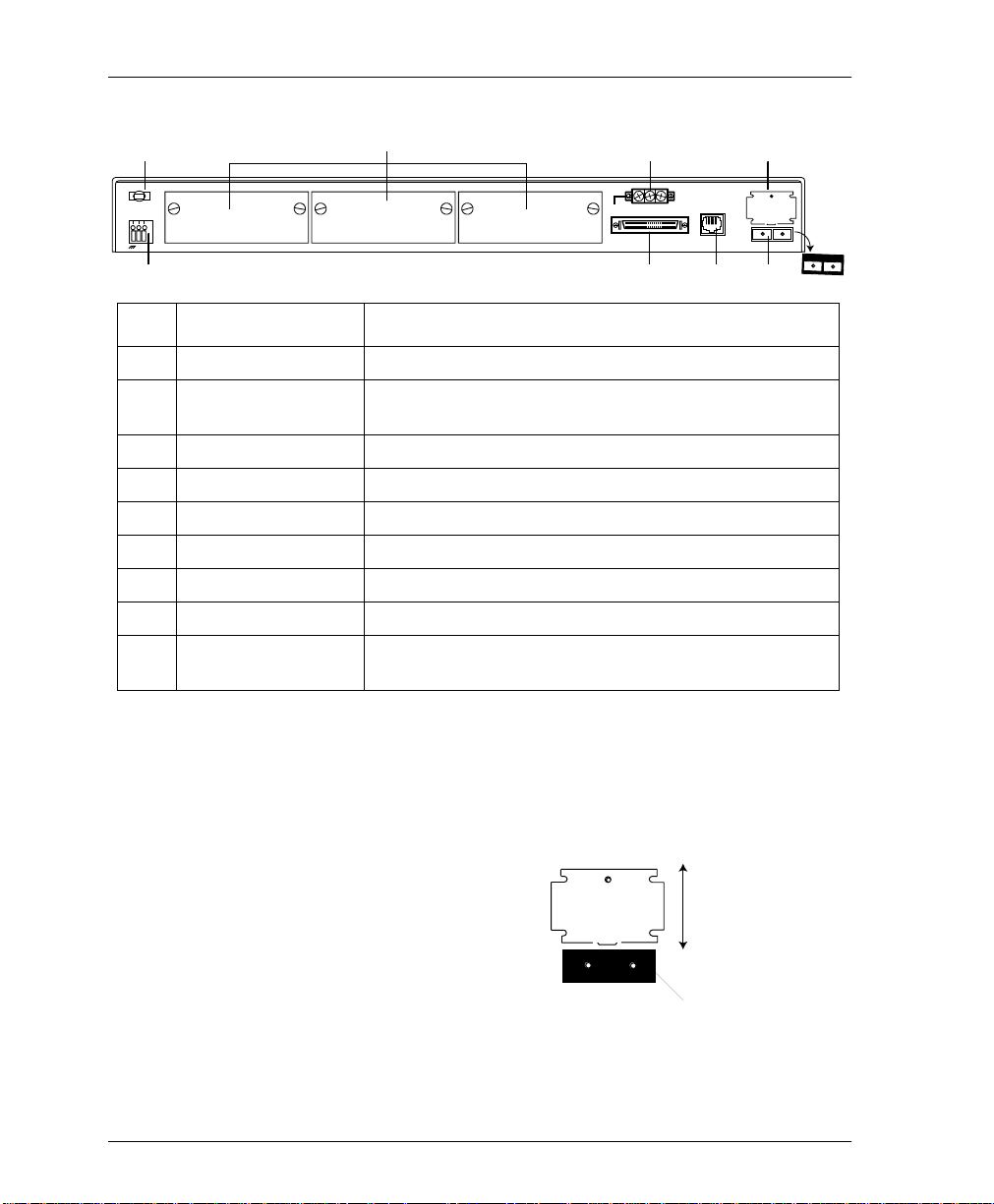
REVIEWING THE REAR PANEL
The OSU 300 rear panel contains a DC terminal block and provides
a strain relief nylon plug that allows you to tie off the input power
cable, thus relieving strain on the cable. The rear panel also
provides three expansion slots, a built-in HSSI interface, an alarm
output terminal block, a LAN port, an optical interface with sliding
door, and a removable dust cover for the optical interface. Pin
assignments for the connectors are given in Appendix A. Figure 2-1
on page 2-4 shows the OSU 300 rear panel, and Figure 2-2 on page
2-4 shows the movement of the optical int erface door.
Chapter 2. Installation and Operation
61200663L1-1 OSU 300 User Manual 2-3
Page 28
Chapter 2. Installation and Operation
1
24-48 VDC
+
-
2
ID #
DTE PORT 4 DTE PORT 3 DTE PORT 2 DTE PORT 1
Item Function
3
5
NC COM NOALARM
4
7
Laser Radiation
Avoid Exposure to Beam
Laser Class 1 Product
Complies with 21 CFR
LAN
6
OPTICAL INTERFACE
8
RX INTX OUT
1 Nylon Plug Provides strain relief on the input power cable.
2 DC Terminal Block Attaches to input power cable for supplying power to the
unit.
3 DTE Ports 2-4 Interface expansion slots (with covers in place).
4 DTE Port 1 Integral HSSI interface.
5 Alarm Connector NC/COM/NO relay contacts.
6 LAN 10BaseT LAN connection.
7 Optical Interface Door Provides protection from laser beam.
8 Optical Interface DS3 service connection.
9 Removable Dust
Cover
Protects unit from dust. Remove to use the Optical
Interface.
9
Figure 2-1. OSU 300 Rear Panel Description
Slide this
Laser Radiation
Avoid Exposure to Beam
Laser Class 1 Product
Complies with 21 CFR
door up and down
to access the
Optical Interface.
OPTICAL INTERFACE
RX INTX OUT
Dust cover in place.
Figure 2-2. Moving the Optical Interfac e Door
2-4 OSU 300 User Manual 61200663L1-1
Page 29
Strain Relief
To relieve strain on the input power cable, the nylon plug ties off
the power cable.
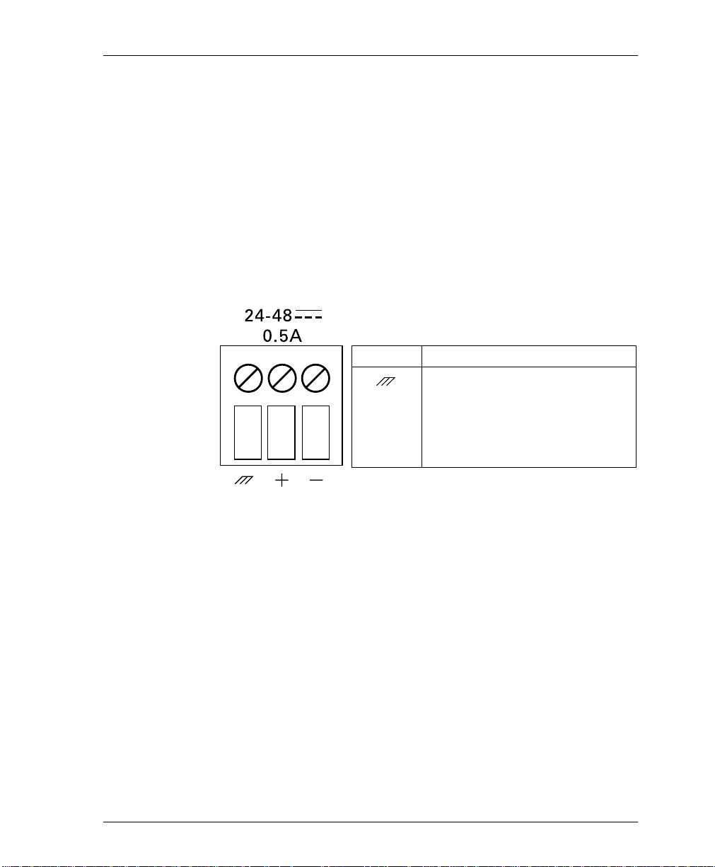
DC Terminal Block
The three-position DC termi nal blo ck accom modates 12 to 26AWG
wire. The positive (+) and negative (-) terminals connect to a 24 to
48 VDC, 0.4A power source. Figure 2-3 illustrates the terminal
block power connector, along with definitions for the three
connector sy mb ols.
Chapter 2. Installation and Operation
Symbol Definition
Frame ground.
+ Positive si de of DC power sour ce
(usually ground).
- Negative side of DC power
source (u sually -48V ).
Figure 2-3. DC Power Connector
DTE Ports 2-4 (Expansion Slots)
The OSU 300 rear panel contains three expansion slots (DTE ports
2-4) for installing opt ional interfa ce cards. Curr ently avail able cards
include the HSSI card (P/N 1200218L1), the V.35 card
(P/N 1200219L1), and the Quad DSX-1 card (P/N 1200284L1). To
insert the cards, follow these steps:
1. Remove the appropriate slot cover from the empty slot.
2. Slide the card into the empty slot until the card panel is flush
with the OSU 300 chassis.
3. Push in the thumbscrews and turn clockwise to secure the card
and ensure proper connection to the main board of the OSU
300.
61200663L1-1 OSU 300 User Manual 2-5
Page 30

Chapter 2. Installation and Operation
DTE Port 1 (HSSI Interface)
DTE port 1 is a built-in HSSI port that resides on the main board of
the OSU 300. Configure the bandwidth of this port in 75 kbps
increments from 75 kbps to 44.2 Mbps. If a single application
requires the full 44.2 Mbps of bandwidth, the OSU 300 does not
have to be equipped with additional port cards. Appendix A
contains the pinout for this port.
Alarm Connector
The alarm connector is a three-position, screw-type terminal block
that connects to the three contacts of a Form C-type relay on the
main board of the OSU 300. This relay activates any time the OSU
300 detects an alarm condition on t he high-speed network
interface. Table 2-1 describes the alarm connector terminal block.
Use the A
disable the alarm function.
LARM RELAY
Table 2-1. Alarm Connector Terminal Block Description
selection of the C
ONFIGURATION
menu to
Position Name Description
Left NC (Normally Closed) Opens when a selected alarm condition is
present.
Center COM (Common) Common connection between external circuitry
and NC or NO terminal.
Right NO (Normally Open) Closes when a selected alarm condition is
present.
LAN Port
The LAN port is an 8-pin modular connector that provides a
10BaseT Ethernet LAN interface. This interface uses SNMP and
Telnet to control the unit. Appendix A contains the pinout for this
port.
2-6 OSU 300 User Manual 61200663L1-1
Page 31

Optical Interface Port
The OSU 300 optical interface port consists of a single-mode or
multi-mode transceiver module comp osed of a transmitter, a
receiver, and an SC or ST receptacle. The optical interface port
supports angled SC type optical connectors (61200663L1 and L2
only) and operates in the 1280 nm to 1335 nm wavelength range
(1310 nm nominal). The total output po wer is 8 mW with a 50 mm
aperture at 10 cm distance, as defined by IEC. The optical interface
uses two fibers, one for each direction of transmission.
The transceiver optical power budgets for the optical transceivers
are 28dB (single-mode) and 9dB (multi-mode). These budgets are
calculated as follows:
Single-Mode
Worst case optical transmit power = -5dBm
Worst case optical receiver sensitivity = -34dB m
Calculations:
(34 - 5) dB = 29 dB - 1dB (optical path penalty) = 28dB
Chapter 2. Installation and Operation
Multi-Mode
Worst case optical transmit power = -20dBm
Worst case optical receiver sensitivity = -30dB m
Calculations:
(30 - 20) dB = 10dB - 1dB (optical path penalty) = 9dB
The optical interface complies with the physical interface
parameters listed in ITU-T recommendation G 957, with IEC Class
1 laser safety requirements (under normal operating conditions)
and with FDA Class 1 laser safety requirements. The OSU 300
contains an integrated automatic shutdown circuit that disables the
laser when it detects transmitter failures, thus the Class 1 rating.
The FITS rating of the internal shutdown circuit is less than 500
FITS.
61200663L1-1 OSU 300 User Manual 2-7
Page 32

Chapter 2. Installation and Operation
The OSU 300 comes with a removable process plug that covers the
optical interface. A mechanical door engages when th e fiber cable is
removed from the optical interface (see also, Figure 2-2 on page
2-4). This door protects the unit from dust in the event of the optical
interface being disconnected, and it provides additional protection
for the human eye from the laser beam.
POWERING THE UNIT
The OSU 300 can be powered from either a standard AC mains
supply or a 48 VDC Supply. When mains powered, the unit
receives power via an external power supply that converts the
mains power to a usable 4 8 VDC source. When powered by the AC
mains supply , the unit operates normally within specification when
supplied with AC voltages from 190–264 VAC at 47–53 Hz. The
48 VDC source interfaces to the rear panel of the unit through a
screw-down terminal block. A nylon plug allows strain relief on the
power cabling to the system.
The chassis should be connected to an earth ground.
The following requirements must be met during installation of the
DC version of the OSU 300:
1. The unit must be connected to a reliably grounded -24 or
-48 VDC source which is electrically isolated from the AC
source.
2. The branch circuit overcurrent protection should be a fuse or
circuit breaker rated 48 VDC, 15 A.
3. The unit should be installed in accordance with the
requirements of NEC NFPA 70.
4. A readily-accessible disconnect device that is suitably
approved and rated should be incorporated in the fixed wiring.
2-8 OSU 300 User Manual 61200663L1-1
Page 33

REVIEWING THE FRONT PANEL
Figure 2-4 illustrates the OSU 300 front panel. Descriptions of each
front panel item follow Figure 2-4.
Chapter 2. Installation and Operation
12 3 4
CONTROL
REMOTE
ACTIVE
IN SERVICE
IN TEST
ALARM
LOS
OPTICAL
INTERFACE
STATUS
IN TEST
TD
RD
DTE PORT 1
STATUS
IN TEST
TD
RD
DTE PORT 2
ID # Item ID # Item
1 Control Port 4 DTE Port LEDs
2 Remote Active Status
3 Optical Interface LEDs In Test
In Service TD
In Test RD
Alarm
LOS
Figure 2-4. OSU 300 Front Pan el
Control Port
The OSU 300 front panel contains an 8-pin modular jack labeled
CONTROL
EIA-232 compatible interface. Appendix A gives the pinout.
. The control port provides connection to a VT-100
STATUS
IN TEST
TD
RD
DTE PORT 3
OSU 300
STATUS
IN TEST
TD
RD
DTE PORT 4
VT-100 Terminal Connection
To control the OSU 300 using a VT-100 terminal, follow this
procedure:
1. Configure the VT-100 terminal for 9600, 19200, 38400, or 57600
baud, 8-bit characters, no parity, and one stop bit (xxxx, 8N1).
61200663L1-1 OSU 300 User Manual 2-9
Page 34

Chapter 2. Installation and Operation
2. Using the ADTRAN-provided terminal interface cable adapter,
connect the DTE port of a terminal to the 8-pin modular jack
labeled
3. Initialize the terminal session and allow approximately 20
seconds for initialization.
4. Press
5. Enter the password. The factory default password is adtran (all
lower-case). The M
6. Make selections by entering the number corresponding to the
chosen parameter. Press
End a terminal session by selecting L
menu or by pressing
CONTROL
repeatedly until the password prompt appears.
Enter
on the front panel of th e OSU 300.
AIN
menu appears (see Figure 2-5).
to return to the previous screen.
Esc
OGOUT
from the M
at any time.
Ctrl-C
AIN
Figure 2-5. OSU 300 Main Menu
2-10 OSU 300 User Manual 61200663L1-1
Page 35

Chapter 2. Installation and Operation
Navigating Within the Menus
Navigate within the OSU 300 termin al menus using the following
procedures:
If you want to... Press...
select an item the number corresponding t o your choice, and
then press the Enter key.
scroll between screens of the same selection the up and down arrow keys. Additional
screens are available when the words Up or
Down display in the right-hand side of the
menu.
scroll left and right of the same screen the left and right arrow keys. Additional
screens are available when
the top portion of the menu.
return to the previous menu the ESC key.
end the terminal session Ctl-C.
refresh the display Ctl-R.
or > display in
<
OSU 300 Main Menus
Status
Provides status information on the network and DTE ports. See the
chapter Status on page 4-1 for more information.
Statistics
Provides statistical information for the network and DTE ports. See
the chapter Statistics on page 5-1 for more information.
Configuration
Sets network, DTE, and system management parameters. See the
chapter Configuration on page 3-1 for more detailed information.
Diagnostics
Performs loopback and BERT tests. See the chapter Diagnostics on
page 6-1 for more detailed i nformation.
61200663L1-1 OSU 300 User Manual 2-11
Page 36

Chapter 2. Installation and Operation
Remote Login
Allows configuration of certain items on the remote OSU 300. The
remote unit’s password is required at login.
Logout
Ends the terminal session and logs out of the system. Password
entry is required before a new session can begin.
Remote Active LED
A solid LED indicates a remote configuration session is taking
place through a T elnet session or from the remote end OSU 300. The
LED flashes when the unit is being accessed locally through the
front panel
CONTROL
Optical Interface LEDs
The following LEDs provide information on the optical interface.
In Service
port.
Active when a valid signal is being received on the optical
interface.
In Test
Active when the network interface has been put in loopback by the
service provider.
Alarm
Active when the high-speed receive signal contains framing errors,
when the yellow alarm is received from the far end unit, or when
other alarm messages are received from the network.
LOS
Active when no receive signal from the network is detected on the
Rx (in) circuit.
2-12 OSU 300 User Manual 61200663L1-1
Page 37

DTE Port LEDs
The following LEDs provide information on DTE ports 1 through 4.
Status
This LED indicates the following conditions:
LED Condition
Off No option card is installed.
Flashing green Interface is available but not configured.
On green Interface is available and configured.
On red DTE fault condition (for HSSI interface, no clock from
On yellow For HSSI inter face, terminal available (TA) sign al inac-
In Test
This LED indicates the DTE interface is performing a BERT test.
Chapter 2. Installation and Operation
DTE).
tive.
TD
This LED indicates the OSU 300 DTE port is transmitting data.
RD
This LED indicates the OSU 300 DTE port is receiving data.
61200663L1-1 OSU 300 User Manual 2-13
Page 38

Chapter 2. Installation and Operation
2-14 OSU 300 User Manual 61200663L1-1
Page 39

Chapter 3
Configuration
The OSU 300 can be configured locally and remotely. Local
configuration is acc omplished through a 10Ba seT Ethernet
connection, a SLIP/PPP port, or a VT-100 terminal. Remote
configuration can take place through the T3 data link using a local
OSU 300.
The C
ONFIGURATION
relating to specific interfaces or functions: DS3 N
P
ORTS
YSTEM MANAGEMENT
, S
menu consists of the following submenus
TILITIES
, U
, and S
ETWORK
AVE CONFIGURATION
, DTE
.
Figure 3-1 shows the main C
ONFIGURATION
terminal menu. De tailed
descriptions of each individual menu parameter are given in the
following sections: DS3 N
3-3), S
YSTEM MANAGEMENT
AVE CONFIGURATION
S
ETWORK
(page 3-11), U
(page 3-18).
(page 3-2), DTE P
TILITIES
(page 3-17), and
ORTS
(page
Figure 3-1. Configuration Main Menu
61200663L1-1 OSU 300 User Manual 3-1
Page 40

Chapter 3. Configuration
DS3 NETWORK
To access the network configuration parameters, select 1- DS3
N
ETWORK
signal received from the service provider. During remote
configuration, this menu is read-only. The DS3 N
ONFIGURATION
C
DS3 N
. Configure the OSU 300 network settings to match the T3
ETWORK
menu is shown in Figure 3-2. Descriptions of the
ETWORK
fields follow the figure.
Figure 3-2. DS3 Network Configuration Menu
DS3 Timing
Set the timing to L
network; set to L
for the circuit.
OOP
if the OSU 300 is to derive timing from the
OCAL
if the unit is to be the master timing source
Remote Auto-Configuration
This feature allows one OSU 300 (set to M
relay its DTE port bandwidth configuration to a second unit (set to
S
LAVE
). If desired, the feature can be disabled by either unit.
ASTER
) to automatically
XCV Threshold
Sets the threshold for code viol at i ons. Options include 1)D
2)1E-3, 3)1E-4, 4)1E-5, and 5)1E-6.
3-2 OSU 300 User Manual 61200663L1-1
ISABLED
,
Page 41

Multiplexing Mode
ULTIPLEXING MODE
The M
bandwidth increment size. The increment size of Nx75 kbps allows
the user to divide 588 blocks among the four ports. The increment
size of Nx3.16 Mbps has 14 blocks available, and ports 2, 3, and 4
are disabled. Only port 1, the built-in HSSI port, is available in this
mode. The Nx3.16 Mbps mode provides compatibility with Juniper
and Cisco routers at below full-bandwidth rates. When the user
switches the multiplexing mode, the system will reboot causing
service interruption. Loading default settings does not reset this
option.
DTE PORTS
Chapter 3. Configuration
menu allows you to select the DTE port
The DTE P
EMOTE AUTO CONFIGURATION
R
DS3 N
a fifth option, T
ORTS
ETWORK
menu allows you to select a port to configure. If
is set to M
EMOTE AUTO CONFIGURATION
-> R
IMED PROFILES
, is available (see Figure 3-3). This
ASTER
ONFIGURATION
(C
ASTER
-> M
), then
option allows you to set up timed profiles specifying bandwidth
allocation for all four ports.
Configuration selections for the individual ports are described in
the following section. A more in-depth description of T
ROFILES
P
is on page 3-10.
IMED
Figure 3-3. DTE Ports Menu
->
61200663L1-1 OSU 300 User Manual 3-3
Page 42

Chapter 3. Configuration
Port Selections 1-4
Select DTE P
ORT
1, 2, 3, or 4 to access the port configuration
parameters. Configure each DTE port to be compatible with the
DTE equipment attached to it. Figure 3-4 shows P
ONFIGURATION
C
menu examples. Descriptions of the individual
ORT
fields follow the illustration. The descriptions are listed in tabl es
based on the DTE port interface type (HSSI, V.35, or Quad DSX-1).
• Table 3-1 on page 3-5 lists the menu fields available for HSSI
and V.35 interfaces.
• Table 3-2 on page 3-6 lists menu fields available only for V.35
interfaces.
• Table 3-3 on page 3-8 lists the menu fields available for Quad
DSX-1 interfaces.
Figure 3-4. Port Configuration Menus for V.35 and HSSI Interface Cards
3-4 OSU 300 User Manual 61200663L1-1
Page 43

Configuration Selections for HSSI and V.35 Interfaces
The configuration selections listed in Table 3-1 are available for
HSSI and V.35 interfaces. Additional selections listed in Table 3-2
on page 3-6 apply only to V.35 interfaces.
s
Table 3-1. HSSI and V.35 Configuration Selections
Chapter 3. Configuration
ELECTION
S
NTERFACE TYPE
I
ORT STATUS
P
I
NACTIVE
A
CTIVE
W
AITING
E
RROR
NOT I
NSTALLED
ORT STATE
P
ESCRIPTION
D
This read-only statu s fie ld sh ows the i nterfac e type of th e sel ected port
(HSSI or V.35).
This read-only status field displays one of the following messages to
show the port status of the sele cted port:
RROR
E
, or
NOT I
NSTALLED
.
NACTIVE
I
,
A
The port is installed, bu t idl e. Ac tiv ate a po rt thro ug h the
CTIVE
ORT STATE
P
,
W
AITING
field of this menu.
The port has been configured and is passing data.
The port has been configured and is waiting for the DTE to issue the
appropriate handshaking signals.
• For the HSSI interface, the terminal equipment available (TA)
signal must be asserted by the DTE.
• For V.35, DTR is required if the TR field in this menu is set to
HEN OFF
W
; otherwise, DTR is ignored.
DLE
I
An error condition such as loss of transmit clock has occurred.
An interface card is not installed in the selected port. If a port is not
installed, the remainde r of th e
ORT CONFIGURATION
P
menu does not
appear.
If a port is installed but not currently in use, set to
NABLED
E
to activate an installed port.
ISABLED
D
. Set to
,
NX75K B
LOCKS
This field determin es the am ount of band width all ocated to t he selecte d
port. For a HSSI interface, the selections are from 1-588 (yielding a
bandwidth of 75.2 kbps to 44.2 Mbps). For a V.35 interface, the
selections are from 1-140 (yielding a bandwidth of 75.2 kbps to 10.5
Mbps). Changes to this field do not take effect until
PPLY SETTINGS
A
is selected.
ORT BANDWIDTH
P
61200663L1-1 OSU 300 User Manual 3-5
This read-only status field shows the amount of bandwidth that will be
available if the selection made in the
NX75K B
LOCKS
field is applied.
Page 44

Chapter 3. Configuration
Table 3-1. HSSI and V.35 Configuration Selections (Continued)
ELECTION
S
NALLOCATED
U
K BLOCKS
75
PPLY SETTINGS
A
ELECTION
S
CS
F
ORCED ON
F
OLLOW
RS
ESCRIPTION
D
This read-only stat us field show s the number of 75k blocks of bandwidth
not already allocated to the four DTE ports.
Select this field after maki ng all configuration changes for the selec t ed
port. The changes are then applied to the unit immediately. Applying the
settings briefly affects all ports of the OSU 300. You may cancel
changes made to the curre nt
the ESC key.
ORT CONFIGURATION
P
menu by pressing
Additional configuration selections are available for V.35 interfaces.
These selectio ns are listed in Table 3-2.
Table 3-2. Additional V.35 Interface Port Configuration Selections
ESCRIPTION
D
Selects the control mode for the clear to send (CS) lead.
The CS lead remains on and request to send (RS) is ignored
as long as the unit is synchronized and able to pass data.
The CS state matches the RS state.
TR
I
GNORED
I
DLE WHEN OFF
SR
F
ORCED ON
OFF W
3-6 OSU 300 User Manual 61200663L1-1
OOS/OOF
HEN
Selects the OSU 300’s response to the data terminal ready
(TR) lead.
The OSU 300 ignores the state of the TR lead.
The OSU 300 suspends traffic on the selected port if the TR
lead is off.
Selects the control mode for the data set ready (SR) lead.
The SR control lead rem ain s o n re gard les s of th e s tate of t he
network.
The SR control lead rem ains on un less the OS U 300 rece ives
an out of service/out of frame (OOS/OOF) condition from the
network.
Page 45

Chapter 3. Configuration
Table 3-2. Additional V.35 Interface Port Configuration Selections (Continued)
ELECTION
S
FF WHEN TEST
O
OFF W
T
EST
OOS/OOF OR
HEN
CD
F
ORCED ON
OFF W
RANSMIT CLOCK
T
OOS/OOF
HEN
ESCRIPTION
D
The SR lead remains on except when the OSU 300 is
executing a test.
The SR lead remains on except when the unit receives an
OOS/OOF condition from the network or when the unit is
executing a test.
Selects the control mode for the carrier detect (CD) lead.
The CD lead remains active at all times.
The CD control le ad remains on unle ss the O SU 300 receives
an OOS/OOF condition from the network.
See the following section for a description of this item.
Transmit Clock
Selects the source of the clock used to transfer data from the DTE to
the OSU 300. Use the following chart to determine your selection:
ELECT
S
N
NVERT
I
ORMAL
... IF...
you want the transmit clock to be derived from the
OSU 300.
your DTE device cannot provide a transmit clock
signal and data errors are pre sent between your DTE
and the OSU 300.
XTERNAL
E
Selecting N
you are transmitting at high rates. This sel ec tio n
eliminates data e rrors caused by excessive delays in
the DTE transmit clock receiver, transmit data driver,
and cable length.
ORMAL
or I
NVERT
clocking options depends on your DTE,
cable length, and cable characteristics. To verify error free operation,
perform a DTE loopback test and a BERT test from the DTE. See the
chapter Diagnostics on page 6-1 for information on performing these
tests.
61200663L1-1 OSU 300 User Manual 3-7
Page 46

Chapter 3. Configuration
Configuration Selections for DSX-1 Interfaces
The configuration selections listed in Table 3-3 are available for
Quad DSX-1 interfaces. Sepa rate s el ect io ns can be made for each of
the four DSX-1 ports of the card. The menu is shown in Fi gure 3-5.
Figure 3-5. Port Configuration Menu for Quad DSX-1 Interface Card
The Quad DSX-1 does not perform ESF to SF (D4) conversion through
the network. Therefore, both ends of the circuit must be configured for the
same framing type.
T a ble 3-3. DSX-1 Interface Port Configuration Selections
ELECTION
S
NTERFACE TYPE
I
ORT STATUS
P
NALLOCATED
U
LOCKS
B
ORT STATE
P
3-8 OSU 300 User Manual 61200663L1-1
75K
ESCRIPTION
D
This read-only status field displ ay s
Quad DSX-1 interface card is installed in the DTE Port card slot.
This read-only status field displ ay s
, or
RROR
E
1 interface.
Displays the amount of bandwidth (in 75k increments) not already
allocated to any of the OSU 300 DTE ports.
If an individual DSX-1 interface is insta lled but not current ly in use, set
ISABLED
to
D
NOT I
. Set to
NSTALLED
, indicating the cu rrent status of t he DSX-
NABLED
E
UAD
Q
DSX-1
NACTIVE
I
to activate a port.
, indicating that a
,
A
CTIVE
,
W
AITING
,
Page 47

Chapter 3. Configuration
Table 3-3. DSX-1 Interface Port Configuration Selections (Continued)
ELECTION
S
RAMING
F
INE CODING
L
INE LENGTH
L
DSX-1 T
OURCE
S
IMING
ESCRIPTION
D
Select the framing format for each individual DSX-1 interface. The
default setting is
for Extended Superframe framing. Select
configured for D4 framing. Select
detect the framing type (
mode, the selected interface toggles between
approximately every ten seconds until it detects valid framing. Note:
D4 is equivalent to superframe format (SF).
Set the line code for each individual DSX-1 interface to match the
connected DTE device. Three choices are available:
and
AMI W/
Set the line length for each DSX-1 in terface according to the dista nce
from the OSU 300 to your DTE device. Set to 7.5 dB if the attached
DTE device only s upports DS-1 levels.
For each Quad DSX-1 card pair (the near-end and far-end Quad
DSX-1 cards), there must be only o ne source of timing. The available
timing sources are described below.
DS3
EMOTE
R
STUFFING
The timing for both the near-e nd and far-end Qu ad DSX1 cards is derived from the DS3 interface. All DTE
devices connected to the DSX-1 interfaces must be
slave timed since both cards source the timing reference
derived from the DS3. Both units must be set to DS3.
The timing source for the Quad DSX-1 card is derived
from the far-end Quad DSX-1 card. Us e this mode i f the
far-end card has a
configuration of
DSX-1 #4
The timing source for the Quad DSX-1 pair is derived
DSX-1 #
X
from one of the four DSX-1 int erfaces. When c onfigured
in this manner, one of the DSX-1 interfaces is slaved to
the DSX-1 interface from your DTE. The remaining three
DSX-1 interfaces, if enabled, source the timing as
derived from the slaved port. The far-end DSX-1
interface must be configu red for
than one Quad DSX-1 card is installed, each card can
have a different timing source configuration.
. Select
ESF
ESF
(AMI coding with bit stuffing).
.
if your DTE device is configured
ESF
if your DTE device is
D4
to allow the interface to
UTO
A
or D4) automatically. When in
and D4
ESF
A
B8ZS, AMI
DSX-1 T
IMING SOURCE
DSX-1 #1, DSX-1 #2, DSX-1 #3
. Note: If more
EMOTE
R
UTO
, or
,
PPLY SETTINGS
A
61200663L1-1 OSU 300 User Manual 3-9
Select this field after making all configuration changes for the
selected port. The changes are then applied to the unit immediately.
Page 48

Chapter 3. Configuration
Timed Profiles
Using this option, you can allocate bandwidth based on the time of
day. For example, you can assign more bandwidth to the corporate
LAN during business hours and more bandwidth to a backup
machine in the evenings. The OSU 300 can store two separate user
profiles which have bandwidth selections for each of the four ports.
See Figure 3-6 and Figure 3-7.
IMED PROFILE
T
CONFIGURATION
LAVE
and S
ETWORK
N
Bandwidth Profiles 1 and 2
The P
ROFILE CONFIGURATION
TATUS
S
and N
page 3-5 for descriptions of these options. This screen also allows
you to enable or disable each individual DSX-1 interface of a Quad
DSX-1 card at the time of date specified in the given profile.
Settings for all port types are assigned to the selected profile (1 or 2)
and will apply whenever that profile is active (see Figure 3-7 on
page 3-11).
selections are only available if the R
selection is set to M
on the far-end OSU 300 (C
EMOTE AUTO-CONFIGURATION
-> R
ASTER
ONFIGURATION
Figure 3-6. Timed Profiles Screen
menus allow you to change the P
X75K BLOCKS
options for HSSI and V.35 ports. See
EMOTE AUTO
-
on the near-end OSU 300
-> DS3
).
ORT
3-10 OSU 300 User Manual 61200663L1-1
Page 49

Profile Switch Time (1 and 2)
Enter the time that you want the profile to become active. Enter the
time in military time (i.e., 00:00:00 = 12 AM). The profile remains
active until one of the following occurs: (1) the other profile’s
activation time comes about, or (2) the profile is disabled manually
through the A
Chapter 3. Configuration
Figure 3-7. Example of a Profile Configuration Men u
CTIVE PROFILE
selection.
Active Profile
Use this field to either manually force a profile to become active
(regardless of the time of day) or to disable the profiles completely.
SYSTEM MANAGEMENT
YSTEM MANAGEMENT
The S
allow you to configure the OSU 30 0 for management through
SNMP, Telnet, or a VT-100 interface. Embedded SNMP and Telnet
are available thr ough either a SLIP/PPP or a 10Bas eT Ethernet port.
Scroll between the two menus using the up and down arrows on
your keyboard.
61200663L1-1 OSU 300 User Manual 3-11
menus (see Figure 3-8 on page 3-12)
Page 50

Chapter 3. Configuration
Local IP Address
Enter the OSU 300 IP address. This IP address applies to the
Ethernet or auxiliary port (when configured for PPP or SLIP). This
address is available from the network administrator.
Figure 3-8. System Management Configuration Menu
Gateway IP Address
Enter the gateway IP address of the OSU 300. This address is
necessary only if the OSU 300 and the network manager are
connected through a gateway node. If an IP packet is to be sent to a
different network, the unit sends it to the gateway.
Subnet Mask
Enter the subnet mask of the OSU 300. This address is available
from the network administrator.
Read Community Name
Enter the authentication strings used for SNMP mana gement.
Match the OSU 300 to the SNMP manager for read privileges.
3-12 OSU 300 User Manual 61200663L1-1
Page 51

Write Community Name
Enter the authentication strings used for SNMP mana gement.
Match the OSU 300 to the SNMP manager for write privileges.
Trap Community Name
Enter the authentication strings used for SNMP mana gement.
Match the OSU 300 to the SNMP manager for trap privileges.
Trap IP Addresses
Enter up to five SNMP manager IP addresses to which the OSU 300
sends traps.
Trap Generation
This field determines which trap types (if any) are generated by the
unit (see Figure 3-9). Use this menu to enable or disable N
LARM
A
P
ORT
for trap descriptions.
AR END ALARM
, F
, and QDSX A
Chapter 3. Configuration
, MIB II S
LARM
trap types. See T able 3-4 through Table 3-9
TANDARD
ETWORK TEST
, N
EAR END
, DTE
Figure 3-9. Trap Generation Menu
61200663L1-1 OSU 300 User Manual 3-13
Page 52

Chapter 3. Configuration
T a ble 3-4. Near End Alarm Trap Descriptions
Trap Type If ENABLED, this trap is sent...
Red Alarm (LOS) when the unit detects a loss of signal.
Out of Frame
(OOF)
Yellow Alarm
(RAI)
Idle Signal when the unit detects an incoming idle signal (1100) over the entire DS3
Excessive CV
(XCV)
when the u nit detects an out of frame condition.
when the unit detects an incoming RAI signal.
bandwidth.
when the unit detects excessive code violations.
Table 3-5. Far End Alarm Trap Descriptions
RAP TYPE
T
Red Alarm (LOS) when the unit receives indica tion from th e far end uni t through the far end
Out of Frame
(OOF)
Yellow Alarm
(RAI)
Idle Signal when the unit receives indicati on fro m the far end uni t throu gh th e FEAC
IF ENABLED,
alarm and control (FEAC) chann el that the far end unit has los t its receive
signal.
when the unit receives indicati on fro m the far end uni t throu gh th e FEAC
channel that the far end unit has lost frame synchronization with the
network.
when the unit receives indicati on fro m the far end uni t throu gh th e FEAC
channel that the far end unit is receiving an RAI indication from the
network.
channel that the far end unit is receiving an idle signal (1100) over the
entire DS3 payload.
THIS TRAP IS SENT
...
Eqpt. Fail NSA when the unit receives indication from the network through the FEAC
channel of a non-service-affecting failure in the network equipment.
Eqpt. Fail SA when the unit receives indication from the network through the FEAC
channel of a service-affecting failure in the network equipment.
Com. Eqpt. Fail
NSA
3-14 OSU 300 User Manual 61200663L1-1
when the unit receives indication from the network through the FEAC
channel of a non-service-affecting failure in the network common
equipment.
Page 53

Chapter 3. Configuration
Table 3-6. MIB II Standard Trap Descriptions
RAP TYPE
T
Cold Start when the unit is first powered on.
Link Up when the network recovers from a Link Down condition and data
Link Down when a network condition prevents data transmi ssion. Thi s could be either
Auth. Failure when an SNMP request is made with the wrong read or write community
IF ENABLED,
transmission is restored.
an alarm or a network test.
names.
THIS TRAP IS SENT
...
Table 3-7. Network Test Trap Descriptions
RAP TYPE
T
Network Test In when the unit go es i nto a DS3 network tes t, ei ther c omma nded local ly
Network Test Out when the unit is in a DS3 network test and the test is terminated.
IF ENABLED,
or remotely.
THIS TRAP IS SENT
...
Table 3-8. DTE Port Trap Description
RAP TYPE
T
Port Status Change when the unit detects a change in any of the four DTE ports. These
IF ENABLED,
traps may be generated when a DTE interface card is plugged in, a
cord is removed, a port is reconfigured, a port goes into an error
condition due to cabling problems, or a port goes into a test mode.
THIS TRAP IS SENT
...
Table 3-9. Quad DSX-1 Port Trap Description
RAP TYPE
T
QDSX Alarms when any of the DSX-1 ports detects an error condition.
IF ENABLED,
THIS TRAP IS SENT
...
Toggle All Traps
When activated, this entry allows you to toggle ALL alarms
(previously described) between their disabled and enabled states.
61200663L1-1 OSU 300 User Manual 3-15
Page 54

Chapter 3. Configuration
Password
Set the password requ ired at login (up to 32 characters). The default
password is adtran (all lower case).
Terminal Timeout
Set the amount of time the terminal or Telnet session can remain
inactive before requiring re-entry of the password for access. This
option can be disabled or set for 1
MINUTES
60
IP Security
Enable or disable the IP Security option. If enabled, the unit accepts
management commands and Telnet se ssions from the IP addresses
entered into the IP H
IP Hosts
, or
ONE DAY
OSTS
.
fields.
MINUTE
MINUTES
, 5
, 15
MINUTES
,
Enter up to sixteen management station IP addresses from which
the unit should accept management commands. These addresses
are only applicable if IP S
ECURITY
is enabled.
Master Control Port
Enable or disable the M
the unit may be accessed through the craft port.
ASTER CONTROL PORT
option. If enabled,
Slave Control Port
Enable or disable the C
may be accessed through the craft port.
ONTROL PORT
option. If enabled, the unit
Circuit ID
Enter a name to identify the unit for management purposes.
3-16 OSU 300 User Manual 61200663L1-1
Page 55

Date/Time
Alarm Relay
UTILITIES
Chapter 3. Configuration
Enter date and time information. Enter the time in military time
(20:16:00 for 8:16 pm). Enter the month, date, and year (08/02/01).
View this information in the S
Enable if the alarm terminal block (located on the rear of the unit) is
connected to an audible alarm. If enabled, the alarm circuit is
activated when a network alarm occurs.
TILITIES
The U
information (including self-test results), revert to default
configuration settings, or flash load a new version of software. The
U
PDATE FLASH SOFTWARE
configuring the unit locally. The S
in Figure 3-10 on page 3-18. Possible results for the self-test are
listed in the chart on the following page.
menu allows you to view OSU 300 system
TATISTICS
selection is only applicable when
menus.
YSTEM UTILITIES
menu is shown
61200663L1-1 OSU 300 User Manual 3-17
Page 56

Chapter 3. Configuration
.:
F THE SELF-TEST RESULTS ARE
I
PASS the self-test was successful and the unit is ready to
BAD RAM DATA
BAD RAM ADDRESS
BAD CHECKSUM
BAD BOOT SECTOR
DS3F LOOPBACK FAILURE
ARTE TERMINAL LOOPBACK
FAILURE
or
ARTE INTERNAL LOOPBACK
FAILURE
CONFIGURATION CORRUPT select
HEN
... T
...
use.
contact ADTRAN Technical Support. See Customer
Service, Product Support Informatio n, and Training in
the front section of this manual.
AVE CONFIGURATION
S
ONFIGURATION
C
ADTRAN Technical Support.
menu. If condition persists, contact
from the main
Figure 3-10. System Utilities Menu
SAVE CONFIGURATION
AVE CONFIGURATION
The S
configuration changes to nonvol atile memory. If this option is not
selected after making changes to the configuratio n, the un it reverts
to its previous configuration when powered down.
3-18 OSU 300 User Manual 61200663L1-1
selection commits the current
Page 57

Chapter 4
Status
View port status information by selecting 1-S
menu. Information for the network port and the DTE ports is
provided. Figure 4-1 shows the S
TATUS
TATUS
from the M
menu.
Figure 4-1. Status Menu
AIN
61200663L1-1 OSU 300 User Manual 4-1
Page 58

Chapter 4. Status
NETWORK: STATE
This field displays the current condition of the network. Possible
conditions are listed in the following chart.
Condition Description
Normal The OSU 300 is ready to pass data.
Alarm The unit is currently receiving an alarm indication. See the
field in this menu to determine the alarm type.
In Test The unit is currently in test mode. The
information on test type.
IAGNOSTICS
D
menu provid es
LARM STATE
A
NETWORK: ALARM
This field displays the current alarm condition of the OSU 300.
Possible conditions are given in the following chart.
Condition Description
Normal No alarms are currently being received.
Yellow The unit is transmitting a yellow alarm from the network. This alarm is a
signal sent back towa rd the source of a failed tran smit circuit. The X-bits
(X1 and X2) are set to zero.
LOS (Red Alarm) The unit has lost the Rx signal.
OOF The unit detects an out of frame condition from the network.
Idle The unit detects an idle sequence from the network. Service is
immediately available for use.
4-2 OSU 300 User Manual 61200663L1-1
Page 59

Chapter 4. Status
REMOTE STATUS: ALARM
This field displays the current state of the remote link. Possible
states are listed in the following chart.
Condition Description
Normal No alarms are currently being received.
RAI (Yellow Alarm) The unit is transmitting a yellow alarm from the network. This alarm
is a signal se nt back toward the s ource of a failed transmit c ircuit. The
X-bits (X1 and X2) are set to zero.
LOS (Red Alarm) The unit has lost the Rx signal.
OOF The unit detects an out of frame condition from the network.
Idle The unit detects an idle sequence from the network. Service is
immediately available for use.
Eqpt Fail (SA) The network has signaled a service affecting equipment failure
condition.
Eqpt Fail (NSA) The network has signaled a non-service affecting equipment failure
condition.
Com Eqpt Fail (NSA) The network has signaled a non-service affecting common
equipment failure condition.
Unknown The OSU 300 is unable to determine the state of the network or the
remote unit.
REMOTE STATUS: DATA LINK
This field displays the current state of the data link between the
remote and the local OSU 300s. Possible states are listed in the
following chart.
Condition Description
Normal The local unit’s data link is in sync with the remote unit.
Disabled The
Down The local and remote units are not in sync.
61200663L1-1 OSU 300 User Manual 4-3
to
ATA LINK
D
ISABLED
D
option in the
.
ETWORK CONFIGURATION
DS3 N
menu is set
Page 60

Chapter 4. Status
DTE PORTS
The following status informati on is ava ilable for DTE Ports 1-4.
Interface Type
The interface type of the port is shown in this field (HSSI, V.35, or
Quad DSX-1).
Port Status
This field displays the current port status. Possible states are listed
in the following chart.
Condition Description
Inactive The port is installe d, but id le. Acti vate a po rt throug h the
field of the
Active The port has been configured and is passing data.
Error An error condition such as loss of transmit clock has occurred.
In Test The unit is currently in test mode.
Waiting for DTE The port has been configured and is waiting for the DTE to issue the
appropriate handshaking signals. For the HSSI interface, the terminal
equipment available (TA) signal must be asserted by the DTE. For
V.35, DTR is required if the TR field is set to
otherwise, DTR is ignored. The TR field is found in the
ONFIGURATION
C
ORT CONFIGURATION
DTE P
menu.
menu.
DLE WHEN OFF
I
ORT STATE
P
DTE P
;
ORT
Bandwidth
Displays the amount of bandwi dth allocated to this port. This field
does not apply to the Quad DSX-1 interface card.
DTE Leads
If a lead is active on the port, it displays in this field. The leads
differ according to the interface type. This field does not apply to
4-4 OSU 300 User Manual 61200663L1-1
Page 61

Chapter 4. Status
the Quad DSX-1 interface car d. Le ad descript ions fo r both the H SSI
and the V.35 interfaces follow.
T1 Status
This field displays the current status of the Quad DSX-1 interface
card. Some conditions are given for each of the four individual
ports, while others apply to the entire card. Possible states ar e listed
in the following charts.
Condition Description
Status conditions for an individual DSX-1 port
Off The DSX-1 port has been turned off by the user.
OK The DSX-1 port is on and is capable of passing data.
Red The DSX-1 port detects a loss of signal and is in red alarm.
OOF The DSX-1 port detects an out of frame condition from the network.
Yel The DSX-1 port detects a yellow alarm condition.
Blue The DSX-1 port detects a blue alarm condition (unframed all ones).
Tst The DSX-1 port is in test.
Condition Description
Status conditions for the entire Quad DSX-1 card
Initializing The Quad DSX-1 interface card has just been inserted and is
initializing.
Comm Error The OSU 300 unit is unable to communicate with the Quad DSX-1
interface card. If displayed, call ADTRAN Technical Support (refer to
the last page of this manual).
Frame Slip The Quad DSX-1 interface card has detected a frame slip.
PLL Error The Quad DSX-1 interface card is unable to lock on to the timing
source.
61200663L1-1 OSU 300 User Manual 4-5
Page 62

Chapter 4. Status
t
When a DSX-1 port is enabled but is not attached to a DTE device, the
OSU 300 will transmit an unframed all ones con dition (blue alarm) to
the remote si te.
HSSI Interface Leads
TA (terminal available)
Asserted by the DTE to indicate readiness to transmit data.
CA (communications equipment available)
Asserted by the OSU 300 to indicate readiness to transmit data.
LA (loopback circuit A)
The condition reflected by this lead is dependent upon the LB lead.
See Table 4-1.
LB (loopback circuit B)
The condition reflected by this lead is dependent upon the LA lead.
See Table 4-1.
LC (loopback circuit C)
Asserted by the unit to request a loopback from the DTE.
TM (test mode)
Asserted by the OSU 300 when either the network or the port is
being tested.
Both TA and CA must be on before data will flow.
Table 4-1. LA and LB Leads
LA LB Condition
Off Off No test (normal)
On Off Local line loopback
Off On Remote line loopback
On On Local DTE loopback
4-6 OSU 300 User Manual 61200663L1-1
Page 63

V.35 Interface Leads
RS
Request to send.
CS
Clear to send.
CD
Carrier detect.
TR
Data terminal ready.
SR
Data set ready.
LL
Local DTE port loopback.
RL
Remote port payload loopback.
Chapter 4. Status
TM
T es t mode. Asserted by the O SU 300 when either th e network or the
port is being tested.
61200663L1-1 OSU 300 User Manual 4-7
Page 64

Chapter 4. Status
4-8 OSU 300 User Manual 61200663L1-1
Page 65

Chapter 5
Statistics
VIEWING STATISTICAL INFORMATION
To access L
AIN
M
available for both the near and far ends of the network (see Figure
5-1). If a Quad DSX-1 card is installed, the menu item O
TATISTICS
S
provides access to alarm counts for the DSX-1 ports.
OCAL STATISTICS
menu. Alarm information and performance parameters are
appears on the main S
Figure 5-1. Main Local Statistics Menu Screen
menus, select 2-S
TATISTICS
TATISTICS
screen. This selection
from the
THER
61200663L1-1 OSU 300 User Manual 5-1
Page 66

Chapter 5. Statistics
All statistical information is given in screens based on the following
time periods: the current 15-minute interval, a 24-hour history
(divided into 96 15-minute intervals), and the totals for the
previous 24 hours. Also, a cumula t ive alarm count is gi ven. Thi s
count continues indefinitely until reset by the user.
If the D
(C
Alarm History
The OSU 300 keeps track o f yel low a nd r ed al arms for th e near end.
View alarm history information in one of the three time period
selections, or view a cumulative alarm count. Information in these
fields is for the given time period (if any) since the last reset. The
cumulative alarm count continues indefinitely until C
DS3 A
examples of alarm history screens.
ATA LINK
ONFIGURATION
LARM COUNTS
option is disabled, remote statistics are not available
-> F/O N
ETWORK
-> D
ATA LINK
).
LEAR ALL
is selected. See Figures 5-2 through 5-4 for
An alarm history is also available for the individual ports of a Quad
DSX-1 interface card (if installed). Select P
LARM HISTORY
A
(where X is the number of the card slot in which the
ORT X QUAD
DSX-1
Quad DSX-1 card is installed). See Figure 5-5 on page 5-4 for an
example of the 24-hour alarm history for the card.
The count given reflects the number of ti mes the alarm has occ urred
(rather than the number of seconds the alarm was active).
5-2 OSU 300 User Manual 61200663L1-1
Page 67

Chapter 5. Statistics
Figure 5-2. Current Alarm Count
Figure 5-3. 24-Hour Alarm History
When a > or < symbol appears in the upper corner of the screen, you can
use the arrow keys on your keyboard to scroll right or left to view additional information (see Figure 5-3 above).
61200663L1-1 OSU 300 User Manual 5-3
Page 68

Chapter 5. Statistics
Figure 5-4. 24-Hour Alarm Totals
Figure 5-5. Quad DSX-1 24 Hour Alarm History
Performance Parameters
View performance parameter information in one of the three time
period selections. Information in these fields is for the given time
period since the last reset. When viewing the 24-hour history
statistics screen, use the left and right arrow keys to scroll through
all 96 15-minut e in t erval s . S ee F i gures 5-6 through 5-8 fo r exa mpl es
5-4 OSU 300 User Manual 61200663L1-1
Page 69

Chapter 5. Statistics
of the performance parameter screens. Descriptions of each field on
these screens follow the illustrations.
Figure 5-6. Network Statistics Menu for Current 15-Minute Interval
Figure 5-7. Network Port Statistics 24-Hour History
61200663L1-1 OSU 300 User Manual 5-5
Page 70

Chapter 5. Statistics
Figure 5-8. Network Port Statistics Menu (24-Hour Totals)
Interval starting at:
Tim e that t he 15-mi nute in terval began. Thi s fie ld is only di spla yed
in the 24-hour history screen, which gives information f or the
previous 24 hours divided into 15-minute intervals (shown in
Figure 5-7 on page 5-5).
Unavailable Seconds (UAS)
Time in seconds that the network port is unavailable for data
delivery. This means that the T3 link is down or in test, or that the
signaling state is down.
Severely Errored Framing Seconds (SEFS)
Number of seconds with one or more out of frame defects or a
detected incoming AIS.
Line Coding Violations (LCV)
Number of BPVs (bipolar violations) and EXZs (excessive zeros)
that have occurred.
Line Errored Seconds (LES)
Number of seconds in which one or more CVs or one or more LOS
(loss of signal) defects occurred.
P-Bit Errored Seconds (PES)
Number of seconds with one or more PCVs (P-bit coding
violations), one or more out of frame defects, or a detected
5-6 OSU 300 User Manual 61200663L1-1
Page 71

Chapter 5. Statistics
incoming AIS (alarm indication signal). This count is not
incremented when UASs (unavailable seconds) are counted.
P-Bit Severely Errored Seconds (PSES)
Number of seconds with 44 or more PCVs, one or more out of
frame defects, or a detected incoming AIS. This count is not
incremented when UASs are counted.
P-Bit Coding Violations (PCV)
Number of coding violation (CV) error events that have occurred.
C-Bit Coding Violations (CCV)
In C-bit parity mode, this is a count of coding violations reported
via the C-bits or the number of C-bit parity errors that have
occurred.
C-Bit Errored Seconds (CES)
Number of seconds with one or more CCVs, one or more out of
frame defects, or a detected incoming AIS. This count is not
incremented when UASs are counted.
C-Bit Severely Errored Seconds (CSES)
Number of seconds with 44 or more CCVs, one or more out of
frame defects, or a detected incoming AIS. This count is not
incremented when UASs are counted.
F-Bit Errors (FBE)
Number of times an F-bit framing error has occurred.
M-Bit Errors (MBE)
Number of times an M-bit framing error has occurred.
Far-End Block Errors (FEBE)
Number of times a block error has occurred on the far end.
Percent Availability
Time that the network port is available for data delivery.
Clear All Local DS3 Statistics/Refresh All Remote Statistics
Clears or refreshes all current information. These selections affect
all statistical information (not just the displayed screen).
61200663L1-1 OSU 300 User Manual 5-7
Page 72

Chapter 5. Statistics
5-8 OSU 300 User Manual 61200663L1-1
Page 73

Chapter 6
Diagnostics
IAGNOSTICS
The D
tests from the OSU 300. Figure 6-1 on page 6-2 shows the main
D
IAGNOSTICS
individual DTE port. If a Quad DSX-1 card is installed, activate
loopback tests for an entire card (all four DSX-1s) or for an
individual DSX-1 port.
To choose a DTE port from the left column of the menu, select the
port’s corresponding number and press Enter. The individual port
menus provide loopback and BERT selections. BERT configuration
options and results are given in the right column of the main
D
IAGNOSTICS
Diagnostic selections are described in the following portions of this
chapter:
• DS3 on page 6-2
• DTE Ports 1-4 on page 6-3 (HSSI and V.35 Port Options)
• Quad DSX-1 Diagnostic Options on page 6 -7
• BERT Configuration on page 6-12
menu allows you to initiate loopback and BERT
menu. Perform tests for the entire DS3 or for an
menu.
You can only perform a BERT test on one DTE port at a time. If a BERT
test is already in progress and a second BERT test is selected for another
port, the first t est is discontinued.
Loopback tests may be performed simultaneously on all four DTE ports.
61200663L1-1 OSU 300 User Manual 6-1
Page 74

Chapter 6. Diagnostics
DS3
Figure 6-1. Diagnostics Main Menu
When you access the DS3’s diagnostic options by selecting 1 from
the main D
IAGNOSTICS
menu, the screen shown in Figure 6-2
displays.
Figure 6-2. DS3 Diagnostics Menu
Data Mode
Ends a test already in progress for this port.
6-2 OSU 300 User Manual 61200663L1-1
Page 75

DS3 Payload Loopba ck
During this test, all payload information is re-framed and looped
back towards the network. See Figure 6-3 for a block diagram
illustrating the loopback point and the signal paths for this test.
This test does not interrupt data flow from the network to the DTE, but
it does block all DTE-to-network data.
DTE
Chapter 6. Diagnostics
OSU 300
Figure 6-3. DS3 Pay load Loopback Test
BERT
Select BERT to perform a bit error rate test over the entire payload
bandwidth. Only one BERT test may be performed at a time.
Remote DS3 Loopback
This selection initiates a DS3 loopback test f or the remote unit.
Remote DS3 Loopback with BERT
This selection initiates a DS3 loopback test for the remote unit and
sends/checks the BERT pattern over the entire DS3 payload
bandwidth.
DTE Ports 1-4
Access the DTE port diagnostic options by selecting the num ber
corresponding with the desired port (options 2 through 5) from the
61200663L1-1 OSU 300 User Manual 6-3
Page 76

Chapter 6. Diagnostics
main D
IAGNOSTICS
interface type of the selected port. See the following section for the
testing options available for the HSSI and V.35 ports. See Quad
DSX-1 Diagnostic Options on page 6-7 for testing options available
for the DSX-1 ports.
HSSI and V.35 Diagnostic Options
Figure 6-4 shows the available menus when the selected DTE port
is HSSI or V.35. Descriptions of the menus follow the figure.
menu. These options differ depending on the
Figure 6-4. HSSI or V.35 Port Diagnostics Menu
Data Mode
Ends a test already in progress.
Payload Loopback
This selection initiates a P
AYLOAD LOOPBACK
test for all data on the
selected port rather than for the entire DS3. During this test, the
data is looped back in the network direction. Perform this test to
verify the integrity of the portion of the DS3 link connecting the
selected port of the OSU 300 and the remote DTE. This test is nonintrusive to the three other ports (see Figure 6-5 on page 6-5).
This test does not interrupt data flow from the network to the DTE, but
it does block all DTE -to-network data for the selected port .
6-4 OSU 300 User Manual 61200663L1-1
Page 77

Chapter 6. Diagnostics
OSU 300
MUX
DTE
Figure 6-5. Payload Loopback Test
Payload BERT
This selection performs a bit error rate test on the selected port.
This test is non-intrusive to the other three ports. Only one BERT
test may be performed at a time. This test is normally performed
from the remote and local ends simultaneously to determine
whether the errors are coming from the transmit or the receive
direction (see Figure 6-6).
OSU 300
MUX
BERT OUT
DTE
BERT IN
Figure 6-6. Payload BERT Test
DTE Loopback
This test is used to verify proper operation of the link between the
OSU 300 and the terminal equipment. During this test, all data sent
by the terminal equipment is looped back to the terminal
61200663L1-1 OSU 300 User Manual 6-5
Page 78

Chapter 6. Diagnostics
DTE
equipment. Figure 6-7 shows a block diagram illustrating the
loopback point and the signal path.
While in DTE loopback, data from the host is transmitted into the network.
OSU 300
MUX
Figure 6-7. DTE Loopback Test
Payloa d and DTE Loopback
Select this test to perform payload and DTE loopbacks
simultaneously. The individual tests are described on page 6-3 and
page 6-5, respectively . Figure 6-8 shows a block diagram illustrating
this test.
OSU 300
MUX
DTE
Figure 6-8. Payload and DTE Loopback Test
6-6 OSU 300 User Manual 61200663L1-1
Page 79

Remote Port Payload Loopback
This selection initiates a payload loopback on the remote OSU 300
for all data on the selected port. Perform this test to verify the
integrity of the portion of the DS3 link connecting the local DTE
and the selected port of the remote OSU 300. All other ports on both
the local and remote units are unaffected.
Remote Payload Loopback with BERT
Perform this test to verify the integrity of the link between the
selected port of the local OSU 300 and the corresponding remote
OSU 300 port. During this test, the remote unit loops back all data
for the selected port, while the local unit sends and checks the
selected BERT pattern. The loopback point and the signal paths for
the remote OSU 300 are the same as the payload loopback test for
the local OSU 300 (shown in Figure 6-5 on page 6-5).
Quad DSX-1 Diagnostic Options
The menu shown in Figure 6-9 appears if the select ed port is a
Quad DSX-1. Descriptions of the menu s e lections follow the figure.
Chapter 6. Diagnostics
Figure 6-9. Quad DSX-1 Diagnostics Menu
Data Mode
Ends a test already in progress.
61200663L1-1 OSU 300 User Manual 6-7
Page 80

Chapter 6. Diagnostics
#x Payload Loopback
During this test, all payload information on the selected DSX-1
interface is reframed and looped back towards the DTE. See Figure
6-10 for an illustration of this test.
OSU 300
Quad DSX-1
Jitter Attenuator
Framer/Formatter
Elastic Store
DS3 MUX
T3DSX-1
Figure 6-10. T1 Payload Loopback Test
#x Framer Loopback
During this test, all information from the network side (DS3) for the
selected DSX-1 interface is looped back towards the network. See
Figure 6-11 for an illustration of this test.
OSU 300
Quad DSX-1
Jitter Attenuator
Framer/Formatter
Elastic Store
DS3 MUX
T3DSX-1
Figure 6-11. Framer Loopback Test
6-8 OSU 300 User Manual 61200663L1-1
Page 81

Chapter 6. Diagnostics
#x Local Loopback
During this test, all information from the network side (DS3) for the
selected DSX-1 interface is looped back towards the network. This
test is similar to the framer loopback test (described in the previous
paragraph), with the exception that this test penetrates the circuitry
deeper into the Quad DSX-1 interface card. See Figure 6-12 for an
illustration of this test.
OSU 300
Quad DSX-1
Jitter Attenuator
Framer/Formatter
Elastic Store
DS3 MUX
T3DSX-1
Figure 6-12. T1 Local Loopback Test
#x Line Loopback
During this test, all information on the selected DSX-1 interface,
including framing, is looped back towards the DTE. See Figure 6-13
for an illustration of this test.
OSU 300
Quad DSX-1
Jitter Attenuator
Framer/Formatter
Elastic Store
DS3 MUX
T3DSX-1
Figure 6-13. Line Loopback Test
61200663L1-1 OSU 300 User Manual 6-9
Page 82

Chapter 6. Diagnostics
Payload Loopback
During this test, all data for the selected DSX-1 interface is looped
back to the far-end unit. The end result is all DSX-1 interfaces of the
far-end unit are looped back. All other ports are unaffected. See
Figure 6-14 for an illustration of this test.
OSU 300 OSU 300
Quad DSX-1
DSX-1
DS3 MUX DS3 MUX
Local port in
Payload Loopback
T3
Far-end unit
in Data Mode
Figure 6-14. Payload Loopback Test
DTE Loopback
During this test, the combined information from the four DSX-1
interfaces is locally looped at the multiplexer of the OSU 300 back
towards the Quad DSX-1 interface card. The end result of this test is
6-10 OSU 300 User Manual 61200663L1-1
Page 83

Chapter 6. Diagnostics
a loopback of all DSX-1 interfaces towards the DTE. See Figure 6-15
for an illustration of this test.
T3SU 300
OSU 300
Quad DSX-1
DSX-1
T3
DS3 MUX
Figure 6-15. DTE Loopback Test
Payloa d and DTE Loopback
This test is a combination of a payload loopback and a DTE
loopback. All of the near-end and far-end DSX-1 interfaces on the
selected Quad DSX-1 interface card are looped back. See Figure
6-16 for an illustration of this test.
OSU 300OSU 300
Quad DSX-1Quad DSX-1
DS3 MUXDS3 MUX
T3
DSX-1DSX-1
Unit in Data Mode
Port in Payload
and DTE Loopback
Figure 6-16. Payload and DTE Loopback Test
61200663L1-1 OSU 300 User Manual 6-11
Page 84

Chapter 6. Diagnostics
Remote Port and Payload Loopback
During this test, the local unit commands the far-end unit to
perform a payload loopback test for the selected Quad DSX-1
interface card. This results in all of the DSX-1 interfaces in the local
unit being looped back. See Figure 6-17 for an illustration o f this
test.
OSU 300 OSU 300
Quad DSX-1
DSX-1
Far-end unit responds
to port loopback
BERT Configuration
The following options apply to any of the tests involving BERT
testing.
Pattern
Select the desired test pattern for the BERT test (see Figure 6-18 on
page 6-13). The internal test pattern generator can be configured for
the following types of test patterns:
• All zeros • 2^15-1
•All ones •2^23-1
DS3 MUX DS3 MUX
T3
Local port in Remote
Port Payload Loopback
Figure 6-17. Remote Port Payload Loopback Test
The test pattern is used to independently test the operation of the
framing circuitry and the network interface of the OSU 300. Instead
6-12 OSU 300 User Manual 61200663L1-1
Page 85

Invert Pattern
Chapter 6. Diagnostics
of using data from the host, this test uses data generated by the
OSU 300’s internal test pattern generator and detector.
Figure 6-18. BERT Pattern Menu
If set to E
NABLE
, the OSU 300 inverts the transmitted and received
BERT test pattern. This allows the unit to be compatible with test
equipment which generates inverted BERT patterns.
BERT Information Fields
The following five fields provide information about the most
recently issued BERT test. These fields appear in the main
D
IAGNOSTICS
menu (shown in Figure 6-1 on page 6-2).
Port
Displays which port is transmi tting and receiving the BERT
pattern.
Direction
Displays the direction in which the BERT pattern is being sent.
State
Displays either S
YNC
or N
O SYNC
to indicate whether the unit is in
sync with the BERT pattern.
61200663L1-1 OSU 300 User Manual 6-13
Page 86

Chapter 6. Diagnostics
Insert Error
Clear Errors
Reset All Tests
Errors
Displays the number of BERT errors received by the OSU 300 since
the last reset.
Current Err/Sec
Displays the number of BERT errors received by the unit in the last
second.
Inserts one error into the data stream.
Clears the error counts given in the BERT information fields of this
menu.
Discontinues all active tests and clears the counts displayed in the
BERT information fields.
6-14 OSU 300 User Manual 61200663L1-1
Page 87

Chapter 7
Applications
This chapter provides examples of some common T3 applications.
The examples include a single port DSU/CSU full T3 bandwidth
application, a point-to-point multiport application (page 7-2), a
fractional T3 application (page 7-4), a remote SNMP management
application ( page 7-6), and a voice application (page 7-7). The
configuration selections given in these examples may need
modification based on your network configuration.
SINGLE PORT FULL T3 BANDWIDTH
In applications requiring full T3 bandwidth, the OSU 300 operates
with other vendor products that support 44.2 Mbps data over
unchannelized T3 circuits.
In the application shown in Fi gure 7-1, th e OS U 300 provides
network connectivity for a ro uter runnin g at 44. 2 Mbps. The data is
frame relay and the unit is SNMP-managed via th e local Ethernet.
See Table 7-1 on page 7-2 for an example configuration.
Router
44.2 Mbps
61200663L1-1 OSU 300 User Manual 7-1
OSU 300
Figure 7-1. Single Port Application
T3HSSI
Private Fiber
or Packet
Network
Page 88

Chapter 7. Applications
Table 7-1. Single Port Full T3 Bandwidth Application Example
Local OSU 300
DS3 Network DS3 Timing - Loop
DTE 1 Port State - Enabled
Nx75k blocks - 588
DTE 2 Port State - Di sabled
DTE 3 Port State - Di sabled
DTE 4 Port State - Di sabled
System
Management
Local IP Address - 10.4.10.2
Subnet Mask - 255.255.255.0
Gateway IP Address -
10.4.10.1
IP Security - Disabled
Trap IP Address - 10.4.10.10
Management Port - LAN
POINT-TO-POINT MULTIPORT APPLICATION
When networking requirements call for sharing the bandwidth of a
point-to-point T3 circuit, additional data ports can be installed into
the OSU 300 for multiport operation. The OSU 300 supports up to
three port option cards (Quad DSX-1, V.35 or HSSI). These option
cards are hot-swappable and can be field installed. See the section
DTE Ports 2-4 (Expansion Slots) on page 2- 5 for m or e inf ormati on on
card installation. A configuration example of this application using
a Quad DSX-1 card is on page 7-7.
This application (shown in Figure 7-2 on page 7-3) supports two
subnet connections via two different routers, a video conferencing
connection, and a main frame data connection. The OSU 300
supports the high speed data connection requirements of the
routers (using the HSSI ports), as well as the V.35 data connection
requirements of the video conferencing unit and the main frame.
7-2 OSU 300 User Manual 61200663L1-1
Page 89

Chapter 7. Applications
The bandwidth is split by the OSU 300 to provide 18 Mbps for each
router, 1.5 Mbps for the video conference units, and 6 Mbps for the
main frames. See Table 7-2 for an example configuration of this
application.
Main
Frame
Video
Conferencing
V.35
Router Router
HSSI
18 Mbps
1.5 Mbps
HSSI
18 Mbps
V.35
6 Mbps
T3 T3
Private
Fiber
Network
Main
Frame
V.35
6 Mbps
HSSI
18 Mbps
V.35
1.5 Mbps
OSU 300OSU 300
Video
Conferencing
HSSI
18 Mbps
RouterRouter
Figure 7-2. Multiport Application
Ex
Table 7-2. Multiport Application Configuration Example
Local OSU 300 Remote OSU 300
DS3 Network DS3 Framing - C-bit Parity DS3 Timing - Loop
Line Length - Short
DS3 Timing - Loop
Data Link - Enabled
DTE 1 (HSSI) Port State - Enabled Port State - Enabled
Nx75k blocks - 240 Nx75k blocks - 240
DTE 2 (HSSI) Port State - Enabled Port State - Enabled
Nx75k blocks - 240 Nx75k blocks - 240
DTE 3 (V.35) Port State - Enabled Port State - Enabled
Nx75k blocks - 80 Nx75k blocks - 80
DTE 4 (V.35) Port State - Enabled Port State - Enabled
61200663L1-1 OSU 300 User Manual 7-3
Page 90

Chapter 7. Applications
Table 7-2. Multiport Application Configuration Example (Continued)
Local OSU 300 Remote OSU 300
Nx75k blocks - 20 Nx75k blocks - 20
System
Management
Local IP Address - 10.4.10.2 Nothing required. Remote unit
Subnet Mask - 255.255.255.0
Gateway IP Address -
10.4.10.1
IP Security - Disabled
Trap IP Address - 10.4.10.10
Management Port - LAN
can be managed using the local OSU 300.
FRACTIONAL T3 CARRIER APPLICATION
When network providers want to provide service at rates less than
full T3, OSU 300 units can be used in pairs for deploying s ub- T3
rate services.
In this application example (shown in Figure 7-3 on page 7-5), a
carrier provides fractional T3 access at 8 Mbps for internet
connectivity. The data connection can be either V.35 or HSSI at
either location. This network uses a HSSI port at the ca rri e r’s
internet POP (point of presence) and a high-speed V.35 connection
at the customer’ s router. The carrier manages both the local and
remote OSU 300s via SNMP . Table 7-3 on page 7-5 gives an example
configuration for this application.
While in DTE loopback, data from the host is transmitted into the network.
7-4 OSU 300 User Manual 61200663L1-1
Page 91

Chapter 7. Applications
Carrier
Internet
Access
OSU 300
HSSI
8 Mbps
Private
Fiber
Network
RouterRouter
V.35
8 Mbps
OSU 300
Figure 7-3. Fractional Application
Table 7-3. Fractional T3 Application Configuration Example
Local OSU 300 Remote OSU 300
DS3 Network DS3 Framing - C-bit Parity DS3 Framing - C-bit Parity
Line Length - Short Line Length - Short
DS3 Timing - Loop DS3 Timing - Loop
Data Link - Enabled Data Link - Enabled
DTE 1 Port State - Disabled Port State - Disabled
DTE 2 Port State - Enabled Port State - Enabled
HSSI (Local) Nx75k blocks-107 Nx75k blocks-107
V.35 (Remote)
DTE 3 Port State - Disabled Port State - Disabled
DTE 4 Port State - Disabled Port State - Disabled
System
Management
Local IP Address - 12.6.12.2 Nothing required. Remote unit
Subnet Mask - 255.255.255.0
can be managed using the local OSU 300.
Gateway IP Address -
12.6.12.1
IP Security - Disabled
Trap IP Address - 12.6.12.10
Management Port - LAN
61200663L1-1 OSU 300 User Manual 7-5
Page 92

Chapter 7. Applications
REMOTE SNMP MANAGEMENT APPLICATION
A remote OSU 300 can be managed by a local management station
if the remote unit is assigned its own IP address. This address must
be assigned at both the near and far ends. Also, the D
option must be enabled on both units.
In this application example (shown in Figure 7-4) a local OSU 300,
connected to the same LAN as the management station, provides
management access to a remote OSU 300. The local unit has the
remote un it’ s I P a dd r ess in i ts R
IP address is entered into the remote unit’s L
field. Table 7-4 gives an example configuration for this application.
EMOTE
IP A
DDRESS
OCAL
ATA LINK
field. That same
IP A
DDRESS
T3
OSU 300
IP = 10.4.10.3IP = 10.4.10.2
OSU 300
IP = 10.4.10.3
Figure 7-4. Remote Management Application
Table 7-4. Configuration Example for Remote SNMP Management Application
System
Management
Table 7-5. Local OSU 300
Local IP Address - 10.4.10.2 Local IP Address - 10.4.10.3
Subnet Mask - 255.255.255.0 Subnet Mask - 255.255.255.0
Gateway IP Address -
Remote OSU 300
Gateway IP Address - 0.0.0.0
10.4.10.1
Remote IP Address - 10.4.10.3 Remote IP Address - 0.0.0.0
Management Port - LAN Management Port - FDL
7-6 OSU 300 User Manual 61200663L1-1
Page 93

VOICE APPLICATION
This voice application is similar to the point-to-point multiport
application (described on page 7-2). This application (shown in
Figure 7-5) uses two of the four DSX-1 ports on the Quad DSX-1
card to transport PBX data, including voice channels, through the
same T3 as the data. See Table 7-5 for an example configuration of
this application.
Chapter 7. Applications
Video
Conferencing
PBX
Quad
DSX-1
Router Router
V.35
1.5 Mbps
HSSI
18 Mbps
Main
Frame
V.35
6 Mbps
Private
Fiber
Network
Main
Frame
V.35
6 Mbps
T3T3
Video
Conferencing
V.35
1.5 Mbps
OSU 300OSU 300
HSSI
18 Mbps
Figure 7-5. Voice Application
Table 7-6. Configuration Example for a Voice Application
Local OSU 300 Remote OSU 300
DS3 Network DS3 Framing - C-bit Parity DS3 Timing - Loop
Line Length - Short
DS3 Timing - Loop
Data Link - Enabled
DTE 1 (HSSI) Port State - Enabled Port State - Enabled
Quad
DSX-1
PBX
Nx75k blocks - 240 Nx75k blocks - 240
DTE 2 (HSSI) Port State - Enabled Port State - Enabled
Nx75k blocks - 80 Nx75k blocks - 80
61200663L1-1 OSU 300 User Manual 7-7
Page 94

Chapter 7. Applications
Table 7-6. Configuration Example for a Voice Application (Continued)
Local OSU 300 Remote OSU 300
DTE 3 (V.35) Port State - Enabled Port State - Enabled
Nx75k blocks - 20 Nx75k blocks - 20
DTE 4
(Quad DSX-1)
System
Management
DSX-1 Port 1:
Port State - Enabled
Framing - ESF
Line Coding - B8ZS
Line Length - 0 to 133 feet
DSX-1 Port 2:
Port State - Enabled
Framing - ESF
Line Coding - B8ZS
Line Length - 0 to 133 feet
DSX-1 Timing Source - DS3
DSX-1 Port 1:
Port State - Enabled
Framing - ESF
Line Coding - B8ZS
Line Length - 0 to 133 feet
DSX-1 Port 2:
Port State - Enabled
Framing - ESF
Line Coding - B8ZS
Line Length - 0 to 133 feet
DSX-1 Timing Source - DS3
Local IP Address - 10.4.10.2 Nothing required. Remote unit
Subnet Mask - 255.255.255.0
can be managed using the lo-
cal OSU 300.
Gateway IP Address -
10.4.10.1
IP Security - Disabled
Trap IP Address - 10.4.10.10
Management Port - LAN
7-8 OSU 300 User Manual 61200663L1-1
Page 95

Appendix A
Pinouts
The following tables give the pin assignments for the connectors
located on the OSU 300. For more information on these connectors,
see the chapter Installation and Operation on page 2-1.
Table A-1. Control Port Pin Assignments
RJ Pin# Function Direction
1GND
2RTSI
3TDI
4DSRO
5RDO
6CTS
7DTRI
*
O
8 DCD O
* Used for hardware flow control.
61200663L1-1 OSU 300 User Manual A-1
Page 96

Appendix A. Pinouts
T a ble A-2. HSSI Interface Pin Assignments
Pin #
(+ side)
Pin #
(- side)
Direction Description
1 26 Signal Ground (SG)
2 27 O Receive Timing (RT)
3 28 O DCE Available (CA)
4 29 O Receive Data (RD)
5 30 O Loopback Circuit C (LC)
6 31 O Send Timing (ST)
7 32 Signal Ground (SG)
8 33 I DTE Available (TA)
9 34 I Terminal Timing (TT)
10 35 I Loopback Circuit A (LA)
11 36 I Send Data (SD)
12 37 I Loopback Circuit B (LB)
13 38 Signal Ground (SG)
14-18 39-43 I Five Ancillary to DCE
19 44 Signal Ground (SG)
20-23 45-48 O Five Ancillary from DCE
24 49 O Test Mode (TM)
25 50 Signal Ground (SG)
A-2 OSU 300 User Manual 61200663L1-1
Page 97

Appendix A. Pinouts
Table A-3. LAN Port Pin Assignments
Pin Name Description
1 TD+ The positive signal for the TD differential pair.
This signal contains the serial output data
stream transmitted onto the network.
2 TD- The negative signal for the TD differential pair
(pins 1 and 2).
3 RD+ The positive signal for the RD differential pair.
This signal contains the serial input data
stream received from the network.
4,5 N/A not used
6 RD- The negative signal for the RD differential pair
(pins 3 and 6).
7,8 N/A not used
T able A-4. V.35 Interface Card Pin Assignments
Pin Name Description
A 101 Protective Ground (PG)
B 102 Signal Ground (SG)
C 105 Request to Send (RTS)
D 106 Clear to Send (CTS)
E 107 Data Set Ready
F 109 Received Line Signal Detector (CD)
H – Data Terminal Ready (DTR)
J – not used
L – Local Loopback (LL)
61200663L1-1 OSU 300 User Manual A-3
Page 98

Appendix A. Pinouts
Table A-4. V.35 Interface Card Pin Assignments (Continued)
Pin Name Description
N – Remote Loopback (RL)
R 104 Received Data (RD-A)
T 104 Received Data (RD-B)
V 115 Receiver Signal Element Timing (SCR-A)
X 115 Receiver Signal Element Timing (SCR-B)
P 103 Transmitted Data (SD-A)
S 103 Transmitted Data (SD-B)
Y 114 Transmitter Signal Element Timing (SCT-A)
AA 114 Transmitter Signal Element Timing (SCT-B)
U 113 External TX Signal Element (SCX-A)
W 113 External TX Signal Element (SCX-B)
NN – Test Indicator (TI)
Table A-5. Quad DSX-1 Interface Card Pin Assignments
Pin Name Description
1 R1 TXDATA-RING Send data toward DTE
2 T1 TXDATA-TIP Send data toward DTE
3 UNUSED –
4 R RXDATA-RING Receive data from DTE
5 T RXDATA-TIP Receive data from DTE
6,7,8 UNUSED –
A-4 OSU 300 User Manual 61200663L1-1
Page 99

Appendix B
Specifications Summary
SPECIFICATIONS AND FEATURES
This section describes the standa rd specifications and features
incorporated into the OSU 300.
Optical Interface
Clear channel, non-channelized DS3.
Line length: Single-mode (40 Km); multi-mode (2 Km).
Framing format: M13 and C-bit parity.
Line rate: 44.736 Mbps.
Line interface:
SC or ST style connectors for single-mode and multi-mode fiber.
DTE Interface(s)
Integrated HSSI port.
Three option slots accept any combination of interface cards.
HSSI ports are SCSI-II 50-pin female.
V.35 ports are high-speed, M34 female.
DSX-1 ports are RJ-48C, 4-wire.
All option cards are hot-s wappable.
DTE Rates Supported
HSSI port(s) support 75 kbps to 44.2 Mbps.
V.35 port(s) support 75 kbps to 10 Mbps.
DSX-1 ports support up to 1.544 Mbps.
Bandwidth is selectable for V.35 and HSSI in 75 kbps increments.
Clocking
Loop (slaved to network receive clock).
Local (private network master).
61200663L1-1 OSU 300 User Manual B-1
Page 100

Appendix B. Specifications Summary
VT 100 Terminal Interface
RJ-48, EIA -232 compatible, female DB-25 ad apter provided.
Accessible through front or rear panel.
Remote configuration and statistics access available inband.
SNMP/Telnet
Integrated 10BaseT Ethernet and SLIP/PPP (async) port.
MIB II, RFC 1213 and 1407 compliant.
ADTRAN Enterprise MIB for extended monitoring and control/
configuration.
Agency Approvals
FCC Part 15, Class A, UL and CUL
Environment
Operating: 0 to 50 °C (32 to 122 °F)
Storage: -20 to 70 °C (-4 to 158 °F)
Relative Humidity: Up to 95%, non-condensing
Power
AC version: 120 VAC, 9 W
DC version: 24 to 48 VDC, 8W
Physical
Dimensions: 11.625“D x 17.0“W x 1.7“H
(for 1U high 19” rack space)
Weight: 7 lbs.
B-2 OSU 300 User Manual 61200663L1-1
 Loading...