

Page 1
®
Total Access OPTI-3 CPE Wallmount Cabinet
Installation and Maintenance Practice
CONTENTS
1. General .................................................................... 1
2. Installation............................................................... 3
3. System Power Turn-Up........................................... 6
4. Maintenance ............................................................ 7
5. Specifications .......................................................... 7
6. Warranty and Customer Service ............................. 7
FIGURES
Figure 1. Wallmount Cabinet...................................... 1
Figure 2. Wallmount Cabinet Rear View.................... 2
Figure 3. Cabinet Mounting Holes.............................. 3
Figure 4. Wiring Block Diagram................................. 4
Figure 5. Circuit Connections ..................................... 5
TABL ES
Table 1. Associated Documentation............................ 2
Table 2. Specifications ................................................ 7
Section 64150WALO3L7-5A
Issue 1, June 2004
T
T
T
T
S
N
KCU
W
NTWK MON
CUST MON
LBK SEL:
NTWK: 1X & HOLD
CUST: 2X & HOLD
DUAL: 3X & HOLD
STATUS
LOS = RED
AIS = AMBER
C-BIT = GRN
IDLE = AMBER
M13 = GRN
IDLE = AMBER
LBK
FUSE ALARM
LOS = RED
AIS = AMBER
C-BIT
M13
LBK
1212075
NIU3
TESTAPS ACO
ACO
DS3-3
DS3-1
DS3-2
ENABLE
OPTICS
STATUS
T
S
N
KCU
W
NTWK MON
CUST MON
LBK SEL:
NTWK: 1X & HOLD
CUST: 2X & HOLD
DUAL: 3X & HOLD
STATUS
LOS = RED
AIS = AMBER
C-BIT = GRN
IDLE = AMBER
M13 = GRN
IDLE = AMBER
LBK
FUSE ALARM
LOS = RED
AIS = AMBER
C-BIT
M13
LBK
1212075
NIU3
OPTI-3
1184002L1
DS3-1
DS3-2
DS3-3
OPTICS
STATUS
T
S
N
KCU
W
NTWK MON
CUST MON
LBK SEL:
NTWK: 1X & HOLD
CUST: 2X & HOLD
DUAL: 3X & HOLD
STATUS
LOS = RED
AIS = AMBER
C-BIT = GRN
IDLE = AMBER
M13 = GRN
IDLE = AMBER
LBK
FUSE ALARM
LOS = RED
AIS = AMBER
C-BIT
M13
LBK
1212075
NIU3
OPTI-3
1184002L1
TESTAPS ACO
ACO
ENABLE
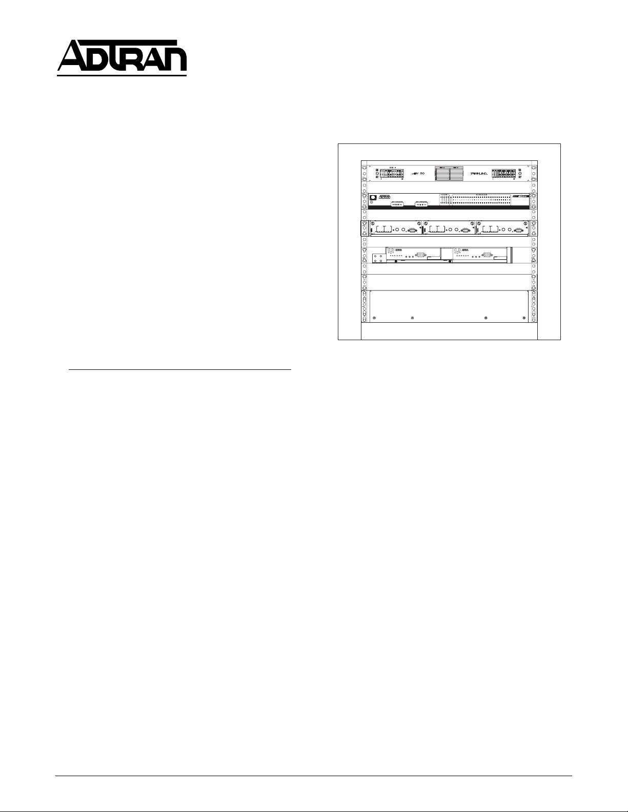
1 RMU Fiber Management Shelf
Battery Backup
Figure 1. Wallmount Cabinet
1. GENERAL
This practice provides installation, wiring, and power
turn-up instructions for the ADTRAN
®
Total Access®
OPTI-3 CPE Wallmount Cabinet (Wallmount Cabinet).
The OPTI-3 deploys fiber-fed DS3s from an OC-3 feed.
The MX2800 converts one of the DS3s into 28 T1s. The
Wallmount Cabinet is intended for indoor use at the
customer premises. Figure 1 illustrates the Wallmount
Cabinet (P/N 4150WALO3L7).
Document Review
This document contains important pre-installation
information. Craft personnel should review the entire
document as part of installation planning.
Revision History
This is the initial release of this document. Future
revisions will be explained in this paragraph.
Description
The Wallmount Cabinet installation includes the
following components:
• Dual hinged 10U wallmount cabinet
• Mounting brackets
• Fiber management shelf
• Fiber splice tray
• six-port fiber connector module
• OPTI-3 rackmount chassis
• MX2800 rackmount chassis
• Two OPTI-3 controllers or lightwave controllers
• SC type optical connectors
• Coax cables and optical jumpers
• NIU3 3-slot shelf
• Three DS3 NIU3 MTC (MPOP) modules
• Two 1.9 amp power supply/battery chargers
• 10x10 fuse and alarm panel
• 7Ah battery backup
Cabinet Arrangement
All Wallmount Cabinet components are factory
mounted and wired for power, ground, and alarms.
Power wiring is complete with the exception of
connecting the keyed plug from the backup battery to
the power supply/battery charger (PS/BC). This wiring
is identified and labeled ready for craft connection after
the unit is securely mounted. Coaxial cables between
the OPTI-3, NIU3, and MX2800 are factory connected.
Optical jumper cables (3 meter) are provided for
customer connection described later in this document.
The Wallmount Cabinet has 10U of vertical rack space
and externally measures approximately 14-1/2-inches
high by 24-inches wide by 17-1/4-inches deep, and
weighs about 140 pounds equipped.
64150WALO3L7-5A PRELIMINARY 1
Trademarks: Any brand names and product names included in this document are
trademarks, registered trademarks, or trade names of their respective holders.
Page 2
The cabinet equipment access door has a full-view
safety-glass window. The swing out equipment housing
section has vent louvers on the top. The wallmount
support frame has cable access openings on the bottom.
A ground bus bar is mounted to the bottom inside of the
cabinet. Vertical equipment racks are sized for 19-inch
chassis components.
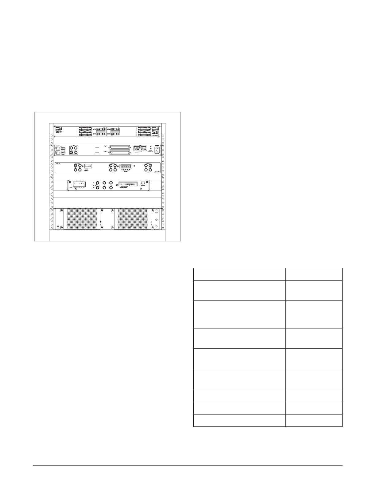
See Figure 2 for a rear view of cabinet arrangement.
1 RMU Fiber Management Shelf
The Trimm 10x10 fuse and alarm (F&A) panel is
mounted topmost in the cabinet. It receives primary and
secondary (redundant) power from the two PS/BCs. The
F&A panel has terminals and fuse protection capability
for primary and secondary power for a fully populated
cabinet plus spare capability for customer use.
Features
The Wallmount Cabinet supports the following features
and functions:
• 19-inch rackmount design
• Key lock security access
• Redundant power capability
• Independent frame ground connections
• Compact configuration
• Convenient access to front and back of chassis
• Factory wired for quick installation and turn-up
• FCC and UL compliant
• Meets NEBS Level 3 (all GR-63-CORE and
GR-1089-CORE requirements)
Figure 2. Wallmount Cabinet Rear View
The cabinet is configured with the two PS/BCs mounted
to a panel installed bottommost in the cabinet. Viewed
from the front, the left side PS/BC is the primary A-unit
and the right side is the redundant B-unit.
Mounted above the power supplies is the fiber
management shelf. It has a swing out door that gives
access to the 6-position fiber termination panel. It is
designed to accommodate fiber cable management for
two OPTI-3 controller modules.
The OPTI-3 chassis is mounted above the fiber
management shelf. It has slots for two OPTI-3 circuit
boards: the in-service unit and an optional redundant
unit if installed. Each OPTI-3 can feed three DS3 NIU3
circuit cards. The design is intended for 1-to-1
protection.
The DS3 NIU3 3-Slot chassis is mounted next above the
OPTI-3. The NIU3 chassis has slots for three NIU3
circuit cards. Three test cards are provided for this
installation: the DS3 Monitor and Test Card
(DS3 MTC), P/N 1212071L1.
Associated Unit Documentation
Individual unit documentation with detailed information exists for each element of the Wallmount
Cabinet solution (see Tabl e 1 ).
Table 1. Associated Documentation
Document ADTRAN P/N
OPTI-3 Rackmount Chassis
61184003L1-22
Job Aid
Total Access OPTI-3
61184002L1-5
Controller Module Installation
and Maintenance Practice
AC/DC Power Supply and
61175043L3-22
Battery Charger Job Aid
DS3 NIU3 3-Slot Shelf Unit
61212073L1-22
Job Aid
DS3 Monitor and Test Card
61212071L1-22
Job Aid
MX2800 Chassis Job Aid
Fiber splice tray Vendor provided
F&A panel guide Vendor provided
61200290L1-22
The MX2800 is mounted above the NIU shelf. It
converts one DS3 into 28 DSX-1s.
2 PRELIMINARY Issue 1, June 2004 64150WALO3L7-5A
Page 3
2. INSTALLATION
The Wallmount Cabinet installs at the customer
premises in a limited access controlled environment
location.
Inspection
After unpacking the Wallmount Cabinet inspect for
damage or missing components. If damage or missing
components are noted, file a claim with the carrier, then
notify ADTRAN. Refer to Warranty and Customer
Service section for more information.
Shipping Protection
Foam material may be installed to protect cabinet
components from shifting during transportation. Ensure
cabling is not damaged during foam removal.
Preparation
The system is shipped as an assembled and wired unit
with the exception of connecting the PS/BC to the
backup battery keyed plugs. Installation includes these
main steps:
I. Mounting the cabinet
II. Making wiring connections
Minimum Front Clearance
The Wallmount Cabinet extends 18 inches from the
mounting surface and requires 40 inches front clearance
from the mounting surface to fully open the door, and
28 inches to fully open the main housing.
NOTE
Craft should double check all dimensions in
this practice to actual dimensions on the
cabinet mounting area.
CAUTION
The cabinet with installed equipment weighs
140 pounds and will require two personnel to
safely lift and hang the cabinet.
The Wallmount Cabinet is designed to mount to a
minimum 3/4-inch plywood surface that is securely
fastened to support frames, studs, wall, or an
arrangement of equivalent strength. The Wallmount
Cabinet installs with standard hand tools; special tools
are not required.
The double hinged cabinet is comprised of three main
elements:
• Front door with full-size transparent window.
• Swing open main housing with heavy-duty hinges
and 19-inch equipment rack.
• Wallmount support frame with mounting brackets,
ground bus bar, and cable entry openings.
Mounting Features and Dimensions
The Wallmount Cabinet occupies a nominal area 24
inches wide by 20.25 inches high and requires an
additional 9 inches on the hinge side so the cabinet main
housing can swing fully open, and 6 inches below for
wire access.
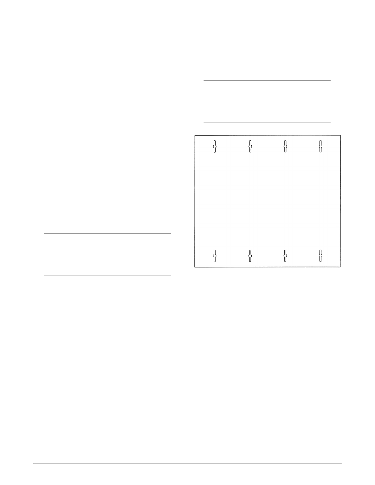
Figure 3. Cabinet Mounting Holes
Pilot Hole Location
The Wallmount Cabinet mounts to the wall using eight
1-1/2 by 1/4-inch lag screws with washers. Pilot holes
must be drilled into the mounting surface at the eight lag
screw positions. Locate and mark pilot holes per the
following directions:
Within the designated area for Wallmount Cabinet
mounting, mark a point for the upper left mounting lag
screw.
1. Exactly 16 inches horizontally to the right from
that point mark the spot for the upper right
mounting lag screw. Ensure a level measurement.
2. The Wallmount Cabinet can be mounted and then
the rest of the mounting screw locations can be
drilled from within the cabinet. Refer to I.
Mounting the Cabinet on page 4.
64150WALO3L7-5A Issue 1, June 2004 PRELIMINARY 3
Page 4

I. Mounting the Cabinet
The following procedure describes Wallmount Cabinet
mounting:
1. Assemble required hand tools and mounting
hardware.
2. Check the mounting position to ensure the
Wallmount Cabinet will hang plumb and that
adequate space exists on the hinge side to open the
equipment rack main housing, then drill the two
pilot holes at the marked point locations.
3. Partially insert the outside two top mounting
screws including washers, leaving about a 1/2-inch
gap between the washer and the mounting surface.
4. Ensure the door and main housing are securely
closed then, with two craft personnel, lift and
maneuver the cabinet so as to capture the two
mounting screws on the bracket keyhole notches,
ensure the washers are on the cabinet side of the
notches. Allow the cabinet to slide down so the
screw heads are at the top end of the slots.
5. With the Wallmount Cabinet thus suspended, hold
firm against the mounting surface and firmly
tighten the two lag screws.
6. Drill the holes for the other six lag screws.
7. Insert and tighten the six lag screws
This completes the Wallmount Cabinet mounting
procedure.
II. Making Wiring Connections
Wallmount Cabinet wiring is labeled and cut to length
with the appropriate terminals or keyed connectors
factory assembled and connected. See Figure 4 for
wiring block diagram identification and arrangement.
See Figure 5 for circuit connections.
A
AC Power to PS/BC A
B
AC Power to PS/BC B
C
Primary Power to F&A Panel
D
Redundant Power to F&A Panel
E
Primary Power to OPTI-3
F
Primary Power to NIU3
G
Primary Power to MX2800
H
Secondary Power to OPTI-3
I
Secondary Power to NIU3
J
Secondary Power to MX2800
PRI SEC
F&A
J
G
MX2800
I
Alarms
NIU3
F
H
E
OPTI-3
PS/BC A
A
C
Alarms
PS/BC B
B
D
Alarms
Figure 4. Wiring Block Diagram
CAUTION
Do not connect AC power until instructed to do
so later in this procedure.
4 PRELIMINARY Issue 1, June 2004 64150WALO3L7-5A
Page 5

A
Network OC-3 Feed to OPTI-3
B
DS3 Signal to NIU3
C
DS3 Signal to Field
D
DS3 Signal IN to MX2800
E
DS3 Signal OUT from MX2800
Alarms
The PS/BCs have an alarm output jack (AC ALARM
OUTPUT). The alarm outputs are joined and are factory
wire-wrapped on terminal posts AUX-1 on the OPTI-3
chassis backplane.
The F&A panel has a fuse fail alarm output that is
factory wire wrapped to AUX-2 on the OPTI-3 chassis
backplane.
MX2800
1 DS3
D
3 DS3s
B
C
Network
A
E
NIU3
Field
OPTI-3
Figure 5. Circuit Connections
A cable access plate on the Wallmount Cabinet bottom
panel provides the entry point for office ground, AC
power, network coax/fiber connections, and other
associated wiring.
Ground
WARNING
All grounds must terminate at an approved
ground source. Check metal to metal contact
on all ground connections. Do not combine or
stack connections. Verify ground circuit continuity.
At the inside bottom left of the wallmount support
frame is the cabinet ground bus bar. It has multiple
screw compression terminals for ground connections.
The ground bus is the primary cabinet ground source.
The bus bar is ground connected to the support frame
with a bolt arrangement. All shelf components are
factory connected to the ground bus bar.
Cabinet Office Ground
Connect a customer-supplied, 10 AWG minimum,
office ground wire to one of the unused compression
terminals on the ground bus bar. This is the primary
cabinet to office ground connection.
Power
The two PS/BC units (A and B) mount to the back side
of the battery. Each PS/BC power output originates at
the –54 VDC, 2A OUTPUT connection, and terminates
at a modular plug at the F&A panel. The F&A panel has
a mating connector for each PS/BC output plug. PS/BC
A supplies F&A panel A-side, PS/BC B supplies the Bside. F&A panel circuitry allows the PS/BC units to
power share with one unit picking up the entire load if
the other unit fails.
Power Distribution and Fuses
The F&A panel has 10 individually fused output
terminals on the A-side and an additional 10 on the
redundant B-side. Terminal sets
1A and 1B supply
primary and secondary power input to the OPTI-3. The
associated front panel GMT fuses are 3 amp. The
OPTI-3 power input and return is on power sharing
terminals labeled
RET.
F&A terminal sets
–48V A and RET, and –48V B and
2A and 2B supply primary and
secondary power input to the NIU3. The associated
front panel GMT fuses are 1.5 amp. The NIU3 power
input and return is on power sharing terminals labeled
–48V A and RET, and –48V B and RET.
F&A terminal sets
3A and 3B supply primary and
secondary power input to the MX2800. The associated
front panel GMT fuses are 3 amp. The MX2800 power
input and return is on power sharing terminals labeled
–48V A and RET, and –48V B and RET.
The remaining F&A output terminals are for customer
use.
NOTE
For a fully redundant system each PS/BC must
have an independent AC power source.
1. Connect PS/BC unit A power wire quick
disconnect to F&A panel A-side quick disconnect.
64150WALO3L7-5A Issue 1, June 2004 PRELIMINARY 5
Page 6

2. Connect PS/BC unit B power wire quick
disconnect to F&A panel B-side quick disconnect.
Refer to System Power Turn-Up below for the
remainder of applying power.
Fiber Optic Jumpers
Fiber optic jumper cables are provided. The 3-meter
cables connect the output of the fiber termination panel
inside the fiber management shelf to the SC style optic
connectors on the OPTI-3 circuit boards.
1. Open the fiber management shelf.
2. Partially insert an OPTI-3 card into the OPTI-3
chassis leaving the board mounted optical
connectors accessible.
3. Carefully route and connect an optic jumper cable
between the fiber termination panel and the
designated OPTI-3 connector. Make use of all
cable protection and management devices.
4. Insert the OPTI-3 card until firmly seated in the
backplane and lock with the lock/eject latch.
5. Repeat the procedure for the remaining OPTI-3
circuit boards.
Network and Field Wiring
The customer is responsible for providing both
network-side and field-side optical fiber and coaxial
cables and making the connections to the appropriate
termination. Refer to the applicable documentation
(Ta bl e 1 on page 2) for information and instructions for
identifying these connections.
Final
All factory installed wiring is dressed and laced during
installation. For those wires that were craft connected,
dress and lace to workmanship standards, take special
care with optical fiber cables. Allow slack for opening
the equipment housing. This completes the wiring
connections.
After all wiring connections are made and verified,
reinstall protective covers and shields that were
removed during the installation process. This step is
necessary to maintain NEBS, UL, FCC, and safety
certification.
3. SYSTEM POWER TURN-UP
System Power Turn-Up assumes that the OPTI-3 and
NIU3 chassis have been outfitted with appropriate
circuit cards, default options factory set, and wiring
connections verified in accordance with the applicable
documentation and this Installation and Maintenance
Practice. If such is not the case complete that task first.
NOTE
Power turn-up should be conducted prior to
connecting network and field data connections.
1. Insert both power supply AC plugs into a 120 VAC
source. The PS/BC LEDs will turn ON green.
The NIU3 status LEDs will turn ON green. The
OPTI-3 LEDs will go through various ON/OFF
sequences. The final OPTI-3 display will show the
STATUS LEDs ON green and the remaining LEDs
ON red or flashing red. Refer to specific unit
documentation for complete LED descriptions.
Test the power share and redundant functioning of
the PS/BCs:
2. Unplug PS/BC unit A AC source. Observe its LED
turning OFF. OPTI-3 and NIU3 LEDs should show
normal, indicating that PS/BC unit B picked up the
load.
3. Reinsert PS/BC unit A AC plug. The PS/BC LED
will turn ON green again indicating normal
operation.
4. Unplug the PS/BC unit B AC source. Observe its
LED turning OFF. OPTI-3 and NIU3 LEDs should
show normal, indicating that PS/BC unit A picked
up the load.
5. Reinsert PS/BC unit B AC plug. Observe its LED
turning ON green indicating normal operation.
For PS/BC LED details, refer to descriptions printed on
the PS/BC chassis, or Job Aid 61175043L3-22.
This completes system power turn-up. If LED indications are normal, operators can proceed with network
and field connections, and management and operation
turn-up functions.
6 PRELIMINARY Issue 1, June 2004 64150WALO3L7-5A
Page 7

4. MAINTENANCE
The OPTI-3 Wallmount Cabinet does not require
maintenance for normal operation.
Fuses
If a fuse fails replace with one of identical size, type,
and rating. Repeated failure indicates a circuit
malfunction.
6. WARRANTY AND CUSTOMER SERVICE
ADTRAN will replace or repair this product within the
warranty period if it does not meet its published specifications or fails while in service. Warranty information
can be found at www.adtran.com/warranty
.
U.S. and Canada customers can also receive a copy of
the warranty via ADTRAN’s toll-free faxback server at
877-457-5007.
PS/BC
The PS/BCs have a 3-amp fuse adjacent to the AC wire.
F&A Panel
The F&A panel has 3 amp GMT fuses in positions 1A
and 1B supplying the OPTI-3, 1.5 amp GMT fuses in
positions 2A and 2B supplying the NIU3, and 3 amp
GMT fuses in positions 3A and 3B supplying the
MX2800.
5. SPECIFICATIONS
Specifications for the Wallmount Cabinet are detailed
in Tabl e 2 .
Table 2. Specifications
Power Supply/Battery Charger
AC Input:
Range:
DC Output:
Fuse Rating
MX2800:
NIU3:
OPTI-3:
Cabinet Physical
Dimensions:
Weig ht :
Environment/Temperature
Operating:
Storage:
Relative Humidity:
115 VAC Nominal
88 to 132 VAC
–54 Volts
3 amp
1.5 amp
3 amp
24 in. W × 14.5 in. H ×
17.25 in. D
140 lbs. fully equipped
–40°C to +50°C
–40°C to +85°C
95% noncondensing
• Request document 414 for the U.S. and Canada
Carrier Networks Equipment Warranty.
• Request document 901 for the U.S. and Canada
Enterprise Networks Equipment Warranty.
Refer to the following subsections for sales, support,
Customer and Product Service (CAPS) requests, or
further information.
ADTRAN Sales
Pricing/Availability:
800-827-0807
ADTRAN Technical Support
Pre-Sales Applications/Post-Sales Technical
Assistance:
800-726-8663
Standard hours: Monday - Friday, 7 a.m. - 7 p.m. CST
Emergency hours: 7 days/week, 24 hours/day
ADTRAN Repair/CAPS
Return for Repair/Upgrade:
(256) 963-8722
Repair and Return Address
Contact CAPS prior to returning equipment to
ADTRAN.
ADTRAN, Inc.
CAPS Department
901 Explorer Boulevard
Huntsville, Alabama 35806-2807
64150WALO3L7-5A Issue 1, June 2004 PRELIMINARY 7
Page 8

8 PRELIMINARY Issue 1, June 2004 64150WALO3L7-5A
®
 Loading...