

Page 1
NuPRO-E42
Full-Size PICMG 1.3 Intel® Core™ i7/i5/i3
LGA 1150 SHB
User’s Manual
Manual Rev.: 2.50
Revision Date: Apr. 24, 2015
Part No: 50-13073-1010
Advance Technologies; Automate the World.
Page 2

Revision History
Revision Release Date Description of Change(s)
1.00 2013/11/26 Preliminary release
2.05 2015/4/24 Various errata rectified, spec updated
ii Revision History
Page 3

NuPRO-E42
Preface
Copyright 2015 ADLINK Technology, Inc.
This document contains proprietary information protected by copyright. All rights are reserved. No part of this manual may be reproduced by any mechanical, electronic, or other means in any form
without prior written permission of the manufacturer.
Disclaimer
The information in this document is subject to change without prior
notice in order to improve reliability, design, and function and does
not represent a commitment on the part of the manufacturer.
In no event will the manufacturer be liable for direct, indirect, special, incidental, or consequential damages arising out of the use or
inability to use the product or documentation, even if advised of
the possibility of such damages.
Environmental Responsibility
ADLINK is committed to fulfill its social responsibility to global
environmental preservation through compliance with the European Union's Restriction of Hazardous Substances (RoHS) directive and Waste Electrical and Electronic Equipment (WEEE)
directive. Environmental protection is a top priority for ADLINK.
We have enforced measures to ensure that our products, manufacturing processes, components, and raw materials have as little
impact on the environment as possible. When products are at their
end of life, our customers are encouraged to dispose of them in
accordance with the product disposal and/or recovery programs
prescribed by their nation or company.
Trademarks
Product names mentioned herein are used for identification purposes only and may be trademarks and/or registered trademarks
of their respective companies.
Preface iii
Page 4
Conventions
Take note of the following conventions used throughout this
manual to make sure that users perform certain tasks and
instructions properly.
Additional information, aids, and tips that help users perform
tasks.
NOTE:
NOTE:
Information to prevent minor physical injury, component damage, data loss, and/or program corruption when trying to com-
CAUTION:
WARNING:
plete a task.
Information to prevent serious physical injury, component
damage, data loss, and/or program corruption when trying to
complete a specific task.
iv Preface
Page 5

NuPRO-E42
Table of Contents
Revision History...................................................................... ii
Preface.................................................................................... iii
List of Figures........................................................................ ix
List of Tables.......................................................................... xi
1 Introduction ........................................................................ 1
1.1 Overview.............................................................................. 1
1.2 Features............................................................................... 1
1.3 Specifications....................................................................... 2
1.4 Block Diagram..................................................................... 4
1.5 Functional Description......................................................... 4
1.6 Mechanical Drawing ............................................................ 7
1.7 I/O Connectivity ................................................................... 8
1.8 Rear Panel I/O Ports............................................................ 8
1.9 Board Layout..................................................................... 11
1.10 Onboard Connectors ......................................................... 12
1.11 Jumpers & Switches .......................................................... 17
1.12 Power Consumption ............................... ... ... ... .... ... ... ... .... . 18
1.13 Package Contents ............................................................. 20
2 Getting Started ................................................................. 21
2.1 Installing the CPU.............................................................. 21
2.2 Installing the CPU Fan and Heatsink................................. 25
2.3 Installing Memory Modules................................................ 25
2.4 Driver Installation.................... ... ... ... .... ... ... ... ... .... ... ... ... .... . 27
2.4.1 Intel® Q87 Express Chipset Driver...........................28
2.4.2 Display Driver........................................................... 28
2.4.3 Ethernet Driver ................................ ... ... .... ... ... ... .... .. 28
Table of Contents v
Page 6

2.4.4 Management Engine.................................................29
2.4.5 USB 3.0 Driver..........................................................29
A Appendix: BIOS Setup.......................................................31
A.1 Starting the BIOS............................................................... 31
A.2 Main Setup......................................................................... 35
A.3 Advanced BIOS Setup....................................................... 36
A.3.1 ACPI Settings ............................................. .... ... ... ....37
A.3.2 Trusted Computing.................................. ... .... ... ... ... .38
A.3.3 CPU Configuration...... ... .... ... ... ... .... ... ... ... ... ..............39
A.3.4 SATA Configuration..................................................41
A.3.5 Intel TXT Configuration.. .... ... ... ... .... ... ... ... ... .... ... ... ... .42
A.3.6 Intel IGD SWSCI OpRegion..................................... .43
A.3.7 USB Configuration....................................................44
A.3.8 Super IO Configuration.............................................46
A.3.9 Hardware Monitor.....................................................47
A.3.10 AMT Configuration............. ... ... ... .... ... ... ... ... .... ... ... ... .48
A.3.11 Serial Port Console Redirection......... ... ... ... .... ... ... ... .49
A.4 Chipset Setup .................................................................... 53
A.4.1 Graphics and Memory Bridge Configuration.............54
A.4.2 PCH Bridge Configuration ........................................55
A.4.3 Management Engine Subsystem..............................57
A.5 Boot Configuration ............................................................. 58
A.6 Security Setup.................................................................... 60
A.7 Exit Menu........................................................................... 61
B Appendix: Watchdog Timer..............................................65
B.1 Sample Code..................................................................... 65
C Appendix: System Resources..........................................69
C.1 System Memory Map......................................................... 69
C.2 Direct Memory Access Channels....................................... 69
C.3 IO Map............................................................................... 70
vi Table of Contents
Page 7

NuPRO-E42
C.4 Interrupt Request (IRQ) Lines............................................ 71
Important Safety Instructions.............................................. 77
Getting Service...................................................................... 79
Table of Contents vii
Page 8

This page intentionally left blank.
viii Table of Contents
Page 9

NuPRO-E42
List of Figures
Figure 1-1: NuPRO-E42 Block Diagram ............................................4
Figure 1-2: NuPRO-E42 Board Dimensions ......................................7
Figure 1-3: Rear Panel I/O Ports........................................................8
Figure 1-4: Connectors and Jumpers................... ... ... ... .... ... ... ... .... .. 11
List of Figures ix
Page 10

This page intentionally left blank.
xList of Figures
Page 11

NuPRO-E42
List of Tables
Table 1-1: NuPRO-E42 General Specifications................................ 3
Table 1-2: NuPRO-E42 I/O Connectivity .......................................... 8
Table 1-3: Core™ i7-4770S Processor Power Consumption .........19
Table 1-4: Core™ i5-4430S Processor Power Consumption .........20
Table C-1: System Memory Map.....................................................69
Table C-2: Direct Memory Access Channels...................................69
Table C-3: IO Map........................................................................... 70
Table C-4: IRQ Lines PIC Mode............. ... ... .... ... ... ... ... .... ... ... ... .... .. 71
Table C-5: IRQ Lines APIC Mode ............. ... .... ... ... ... ... .... ... ... ... .... .. 73
Table C-6: PCI Configuration Space Map....................................... 75
Table C-7: PCI Interrupt Routing Map................. ... ... ... .... ... ... ... .... .. 76
List of Tables xi
Page 12

This page intentionally left blank.
xii List of Tables
Page 13

1 Introduction
1.1 Overview
The ADLINK NuPRO-E42 is a PICMG 1.3 System Host Board
(SHB) supporting the 4th Generation Intel® Core™ i7/i5/i3 and
Pentium® processors in LGA1150 package to deliver a scalable
high performance platform for a wide array of industrial
applications. The NuPRO-E42 supports 22nm process CPUs at up
to 3.5 GHz with integrated graphics and memory controllers,
Direct Media Interface (DMI) and Flexible Display Interface (FDI)
connectivity to the Intel® Q87 Express Chipset. Dual-channel
DDR3 memory is supported up to a maximum of 16 GB in two
DIMM slots.
These advanced features, coupled with PCI Express® x16 expan-
sion capability, dual PCI Express®-based Gigabit Ethernet, SATA
6 Gb/s and USB 3.0 support make the NuPRO-E42 ideal for vision
and automation control applications.
1.2 Features
NuPRO-E42
X Supports Intel® Core™ i7/i5/i3 and Pentium® pr ocessors in
LGA1155 package
X Integrated Intel® HD Graphics
X PCI Express® x16 expansion capability via backplane
X Dual Gigabit Ethernet
X 6x USB 3.0 ports (2x on rear panel, 4x on SHB)
X 4x USB 2.0 ports on backplane
X 4x SATA 6 Gb/s ports on SHB
X 6x COM ports (including 1x RS-232/422/485)
X Watchdog Timer, Hardware Monitor
X Optional HD audio kit (DB-Audio2 daughter board)
X TPM hardware security chip
X RoHS compliant
Introduction 1
Page 14

To purchase the op tional DB-Audio2 daughter board, please
contact your ADLINK sales representative.
NOTE:
NOTE:
1.3 Specifications
System
• Intel® Core™ i7-4770S, 3.1 GHz, 8M Cache, 65W TDP (4C)
CPU
Chipset • Intel® Q87 Platform Controller Hub
Memory
BIOS • AMIBIOS in 64-Mbit SPI Flash
Audio
Watch Dog
Timer
Hardware
Monitor
TPM • Infineon SLB 9635 TT 1.2
Operating
Systems
I/O Interfaces
• Intel® Core™ i5-4570S, 2.9 GHz, 6M Cache, 65W TDP (4C)
• Intel® Core™ i3-4330S, 3.5 GHz, 3M Cache, 54W TDP (2C)
• I ntel® Pentium® G3420, 3.2 GHz, 3M Cache, 54W TDP (2C)
• 2x 240-pin DIMM sockets
• Dual-channel DDR3 1333/1600 MHz (up to 16 GB)
• Intel® High Definition Audio support via DB-Audio2
daughter board
• 1-255 second or 1-255 minute pr ogrammable and can
generate system reset.
• CPU/System temperature, fan speed and onboard DC
voltage
• Windows XP 32-bit
• WIndows 7/8 32/64-bit
• WIndows Server 2008 R2
• Ubuntu 13.1 0
2Introduction
Page 15

• 6x USB 3.0 ports (2x on rear panel, 4x on SHB)
• 4x USB 2.0 on backplan e
• 4x SATA 6 Gb/s on SHB
• 6x serial ports via onboard pin-header
I/O Ports
PCIe/PCI
Integrated • Integrat ed Intel® HD Graphics
External • PCI Express x16
Controller
Ports • Two RJ-45 Ethernet ports
Form Factor • Standard full-size PICMG 1.3 SHB
Dimensions • 338 x 126 mm (L x W)
Operating Temp. • 0ºC to 60ºC
Storage Temp. • -20ºC to 80ºC
Rel. Humidity • 10% to 90% non-cond ensing
Safety • CE, FCC Class A
(5x RS-232, 1x RS-232/422/485 with auto flow control)
• 2x Gigabit Ethernet RJ45 ports
• 1x VGA port (Dsub-15)
• 1x DVI-D via onboard pin-header (opt. cable bracket
• Pin header for HD Audio DB-Audio 2 daughter board
• 1x PS/2 KB/MS via onboard pin header (opt. cabl e bracket)
• PCIe-x16 Gen3, PCIe-x4 and PCI 32bit/33MHz (TI
XIO2001) via golden fingers
Graphics
Ethernet
• Dual Gigabit Ethernet (Intel® I217LM Gigabit Ethernet PHY ,
Intel® I211-AT Gigabit Ethernet Controller)
• Supports Preboot Execution Environment (PXE),
Wake-On-LAN, and Intel® AMT 9.0 on LAN1 (I217LM)
Mechanical and Environment
T able 1-1: NuPRO-E42 General Specifications
NuPRO-E42
)
Introduction 3
Page 16
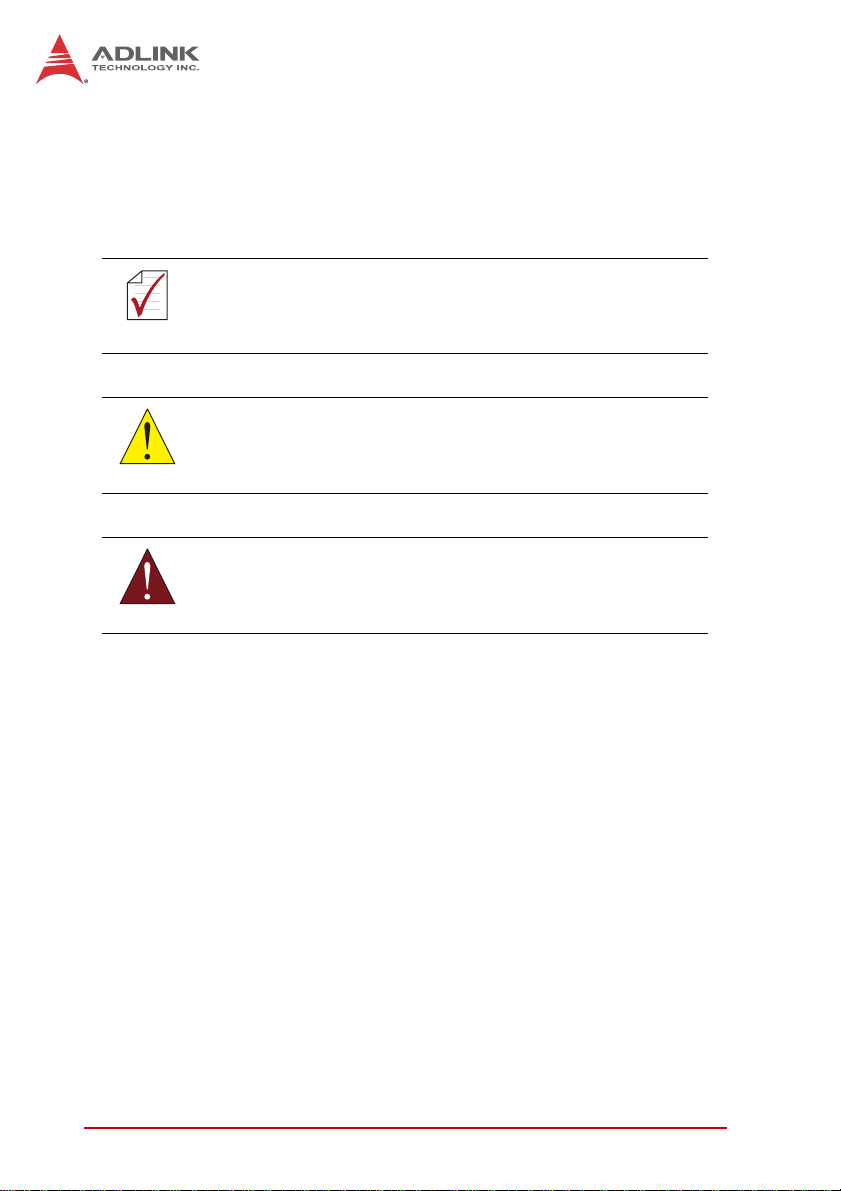
1.4 Block Diagram
Figure 1-1: NuPRO-E42 Block Diagram
1.5 Functional Description
Processor Support
The NuPRO-E42 is PICMG 1.3 System Host Board supporting the
4th Generation Intel® Core™ processor family (Intel® Core™
i7/i5/i3) in LGA1150 socket. An integrated memory controller supports dual channel DDR3 and Intel® HD Graphics is integrated
onboard the CPU. The CPU provides a PCI Express x16 for external graphics or expansion. Direct Media Interface (DMI) and Flexible Display Interface (FDI) pr ovide connectivity to the Intel® Q87
Express Chipset.
Intel® Q87 Express Chipset
The Intel® BD82Q87 Platform Controller Hub (PCH) combines
with the processor to provide a compact yet powerful 2-chip solu-
4Introduction
Page 17

NuPRO-E42
tion. Direct Media Interface (DMI) is the chip-to-chip connection
between the processor and PCH. I ntel® F lexible Dis play Inte rface
carries display traffic from the integrated graphics in the processor
to the legacy display connectors in the PCH. The PCH supports all
other required interfaces including PCI Express, SATA 6 Gb/s,
USB 3.0, PCI, LPC, and SPI.
Dual-Channel DDR3 Memory
To meet the requirements of memory-intensive applications, the
NuPRO-E42 has a dual-channel memory architecture supporting
DDR3 1333/1600 MHz DIMMs. The key advantages of DDR3 are
the higher bandwidth and the increase in performance at lower
power than DDR2. DDR3 memory technology meets the requirements of the latest 3D graphics, multimedia, and network application, and boosts system performance by eliminating bottlenecks.
Gigabit Ethernet
The NuPRO-E42 utilizes an Intel® I217LM Gigabit Ethernet PHY
and Intel® I211-AT Gigabit Ethernet Controller connected to the
PCI-E bus of the Q87 PCH. Intel® AMT 9.0 (I21 7LM on LAN1),
Wake-on-LAN and PXE are supported.
Serial ATA
The NuPRO-E42 provides four Serial ATA ports with data transfer
rates of up to 6.0 GB/s. Intel® Rapid Storage Technology supports
AHCI and RAID 0/1/5/10 functionality.
Universal Serial Bus (USB 2.0/3.0)
The NuPRO-E42 provides 4 USB 2.0 ports (backplane) supporting
transfer rates up to 480 Mb/s and 6 USB 3.0 ports (2x on rear
panel, 4x on SHB) supporting transfer rates up to 5Gb/s. All ports
are USB 2.0/1.1 compatible.
Hardware monitoring
A built-in, proactive hardware monitoring system in the Super I/O
monitors the CPU temperature, system fan speed, and voltage
levels to prevent overheating and/or component damage, effect
Introduction 5
Page 18

timely failure detection, and ensure stable supply of current for
critical components.
Watchdog Timer
The watchdog timer (WDT) monitors system operations based on
user-defined configurations. The WDT can be programmed for different time-out periods, such as from 1 to 255 seconds or from 1 to
255 minutes. The WDT generates a reset signal, then a reset
request, after failure to strobe it within the programmed time
period. A register bit may be enabled to indicate if the watchdog
timer caused the reset event. The WDT register is cleared during
the power-on sequence to enable the operating system to take
appropriate action when the watchdog genera tes a reboot.
Trusted Platform Module
The NuPRO-E42 optionally supports TPM ver. 1.2 (Trusted Platform Module) for secure storage of keys, passwords and digital
certificates. Systems supporting TPM offer improved hardware-based security in numerous applications, such as file and
folder encryption, local password management, S-MIME e-mail,
VPN and PKI authentication and wireless authentication for
802.1x and LEAP.
Intel® Active Management Technology
Intel® Active Management Technology (Intel® AMT) is hardware-based technology for remot ely managing and securing PCs
out-of-band. Intel® AMT includes hardware-based remote management, security, power-management, and remote-configuration
features. Intel® AMT allows remote access to a system when traditional techniques and methods are not availa b l e.
6Introduction
Page 19
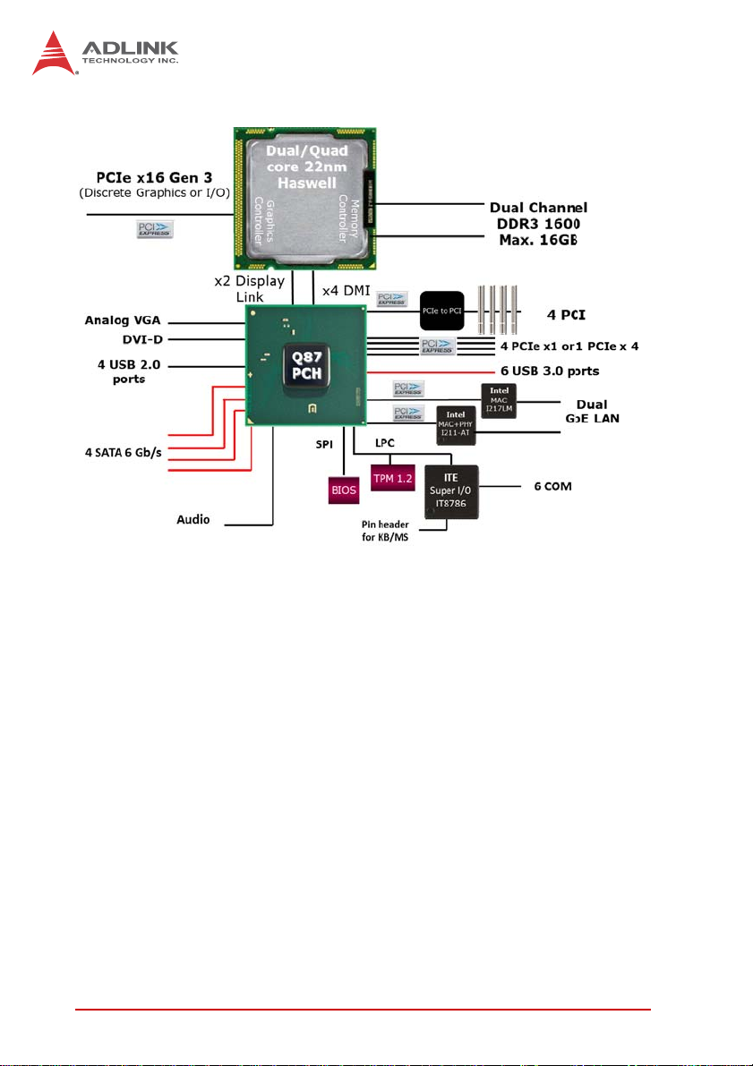
1.6 Mechanical Drawing
117
111
38.5
NuPRO-E42
6
6.5
146
333.6
338.1
4.92
20.59
123.09
Dimensions
in mm
Figure 1-2: NuPRO-E42 Board Dimensions
Introduction 7
Page 20
1.7 I/O Connectivity
I/O Bracket Onboard
VGA Y — — DB-15
DVI-D — Y —
LAN1/2 (RJ-45)
PS/2 KB/MS
USB Rear Panel 2 — — USB 3.0
USB 3.0 headers
USB backplane — — 4 USB 2.0
COM1-2 — Y —
COM3-6 — Y —
SATA — 4 — —
PCIe x4 — — Y —
PCIe x16 — — Y —
PCI 32bit/33MHz — — Y via TI XIO2001
Table 1-2: NuPRO-E42 I/O Connectivity
Y——
—Y—
—4—
Golden
Finger
Remarks
cable w/ bracket
optional
Act/Link/
Speed LEDs
cable w/ bracket
optional
cable w/ bracket
optional
2.54” pitch
2.00" pitch
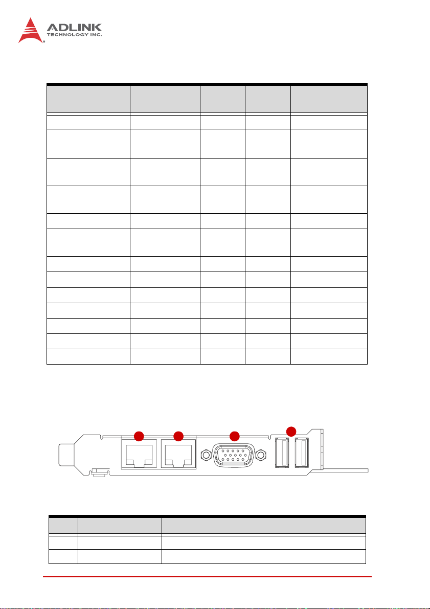
1.8 Rear Panel I/O Ports
1 2 3
Figure 1-3: Rear Panel I/O Ports
Connector Description
1 LAN1 port (RJ-45) Gigabit Ethernet (supports Intel® AMT)
2 LAN2 port (RJ-45) Gigabit Ethernet
8Introduction
4
Page 21
Connector Description
3 VGA port DB-15 connector for CRT or LCD monitor
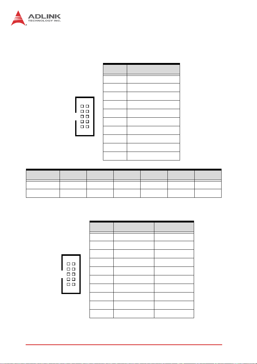
4 USB 3.0 ports SuperSpeed USB 3.0 ports
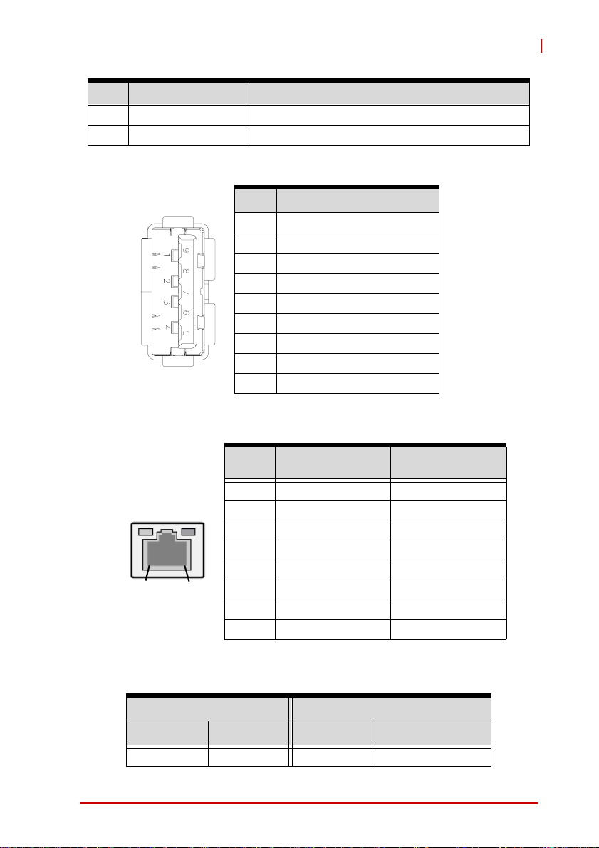
USB 3.0 Connectors
Pin # Signal Name
1 USB3.0_P5V A
2 USB2_CMAN
3 USB2_CMAP
4GND
5 USB3A_CMRXN
6 USB3A_CMRXP
7GND
8USB3A_CMTXN
9 USB3A_CMTXP
LAN (RJ-45) Ports
NuPRO-E42
10BASE-T/100BA
SE-TX
1 TX+ BI_DA+
2 TX- BI_DA3 RX+ BI_DB+
4 -- BI_DC+
5 -- BI_DC6 RX- BI_DB7 -- BI_DD+
8 -- BI_DD-
1000BASE-T
LED1
Pin #
LED2
18
Refer to the table below for the LAN port LED definitions.
LED1 LED2
Status Description Status Description
Off No Link Off 10 Mb connection
Introduction 9
Page 22
On Linked Green 100 Mb connection
Blinking Data Activity Amber 1 Gb connection
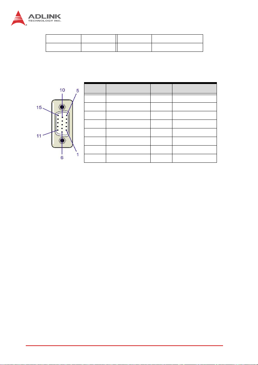
VGA Port
Pin # Signal Pin # Signal
1Red9+5 V
2 Green 10 Ground
3Blue11NC
4 NC 12 DDC DAT
5 Ground 13 HSYNC
6 Ground 14 VSYNC
7 Ground 15 DDC CLK
8 Ground
10 Introduction
Page 23
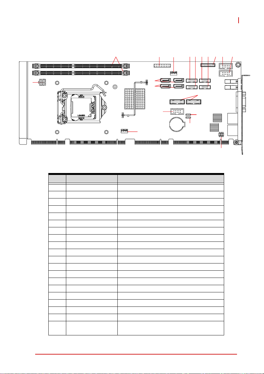
1.9 Board Layout
NuPRO-E42
3
42
1
5
6
15
19
8 9 10 11 12 13
7
14
16
17
18
Figure 1-4: Connectors and Jumpers
Connector Description
1 CN24 ATX 12V Power connector
2 CN28/29 DDR3 DIMM slots
3 CN45 System Panel pin header
4 FAN1 CPU fan connector
5 CN30/32 SATA 6 Gb/s connectors
6 CN31/33 SATA 6 Gb/s connectors
7 CN16 COM6 connector
8 CN14 COM5 connector
9 CN13 COM4 connector
10 CN12 COM3 connector
11 CN17 DVI-D pin header
12 CN23 COM1 connector
13 CN11 COM2 co nnector
14 CN36/37 USB 3.0 pin headers
15 CN40 HD Audio Daughter Board pin header
16 JBAT2 Clear RTC
17 JBAT1 Clear CMOS
18 CN27 PS/2 Keyboard/Mouse pin header
19 FAN2 System fan connector
20 SW13
COM1 mode switch (on solder side, near
the rear I/O USB 3.0 connectors)
Introduction 11
Page 24
1.10 Onboard Connectors
COM1~6 Connector (RS-232) (CN11~14/16/23)
Pin # RS-232 Signal
1DCD
2DSR
3RXD
12
910
COM1 COM2 COM3 COM4 COM5 COM6
Connector CN23 CN16 CN11 CN12 CN13 CN14
Pitch 2.54 mm 2.54 mm 2.00 mm 2.00 mm 2.00 mm 2.00 mm
COM1 Connector (RS-422/485) (CN23)
4RTS
5TXD
6CTS
7DTR
8RI
9GND
10 NC
Pin # RS-422 RS-485
1 TXD- Data2NC NC
3TXD+ Data+
12
4NC NC
5RXD+ NC
910
6NC NC
7RXD- NC
8NC NC
9GND GND
10 NC NC
12 Introduction
Page 25
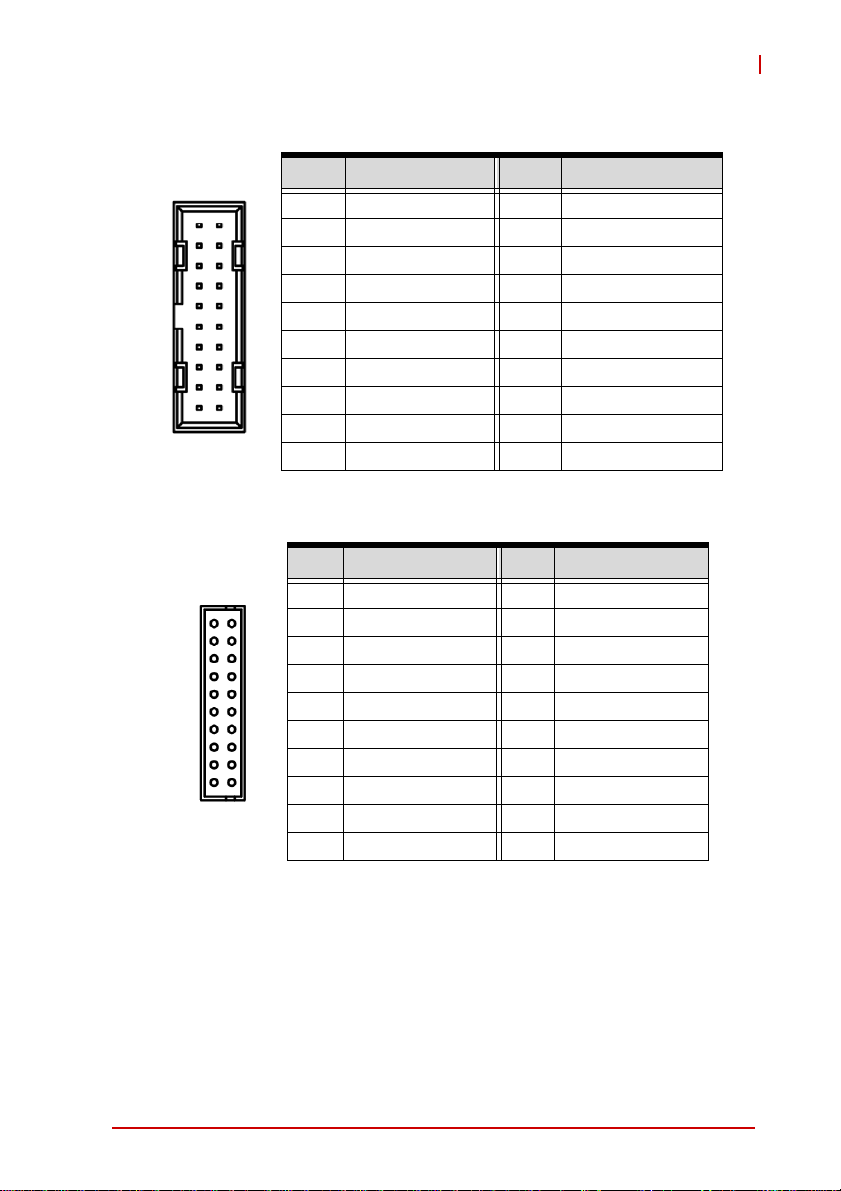
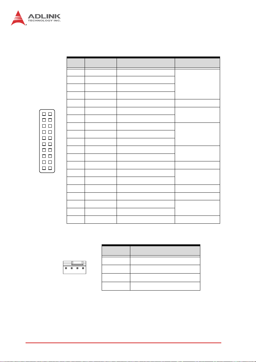
USB 3.0 Connectors (CN36/37)
Pin # Signal Pin # Signal
1 P5V_USB3B 20 NC
2 S_USB3_RN3_R 19 P5V_USB3B
3 S_USB3_RP3_R 18 S_USB3_RN4_R
4 GND 17 S_USB3_RP4_R
5 S_USB3_TN3_R 16 GND
6 S_USB3_TP3_R 15 S_USB3_TN4_R
7 GND 14 S_USB3_TP4_R
1
8 S_USB2_N2_R 13 GND
20
9 S_USB2_P2_R 12 S_USB2_N3_R
10 S_USB_OC1# 11 S_USB2_P3_R
DVI-D Onboard Connector(CN17)
Pin # Signal Pin # Signal
1 GND 2 GND
1
2
3 DVI-Clock+ 4 DVI-Data05 DVI-Clock- 6 DVI-Data0+
7 GND 8 GND
9 DVI-I2C-Clock 10 DVI-Data1-
11 DVI-I2C-Data 12 DVI-Data1+
13 GND 14 GND
15 DVI-HPD 16 DVI-Data217 +5V 18 DVI-Data2+
19 GND 20 GND
NuPRO-E42
Introduction 13
Page 26
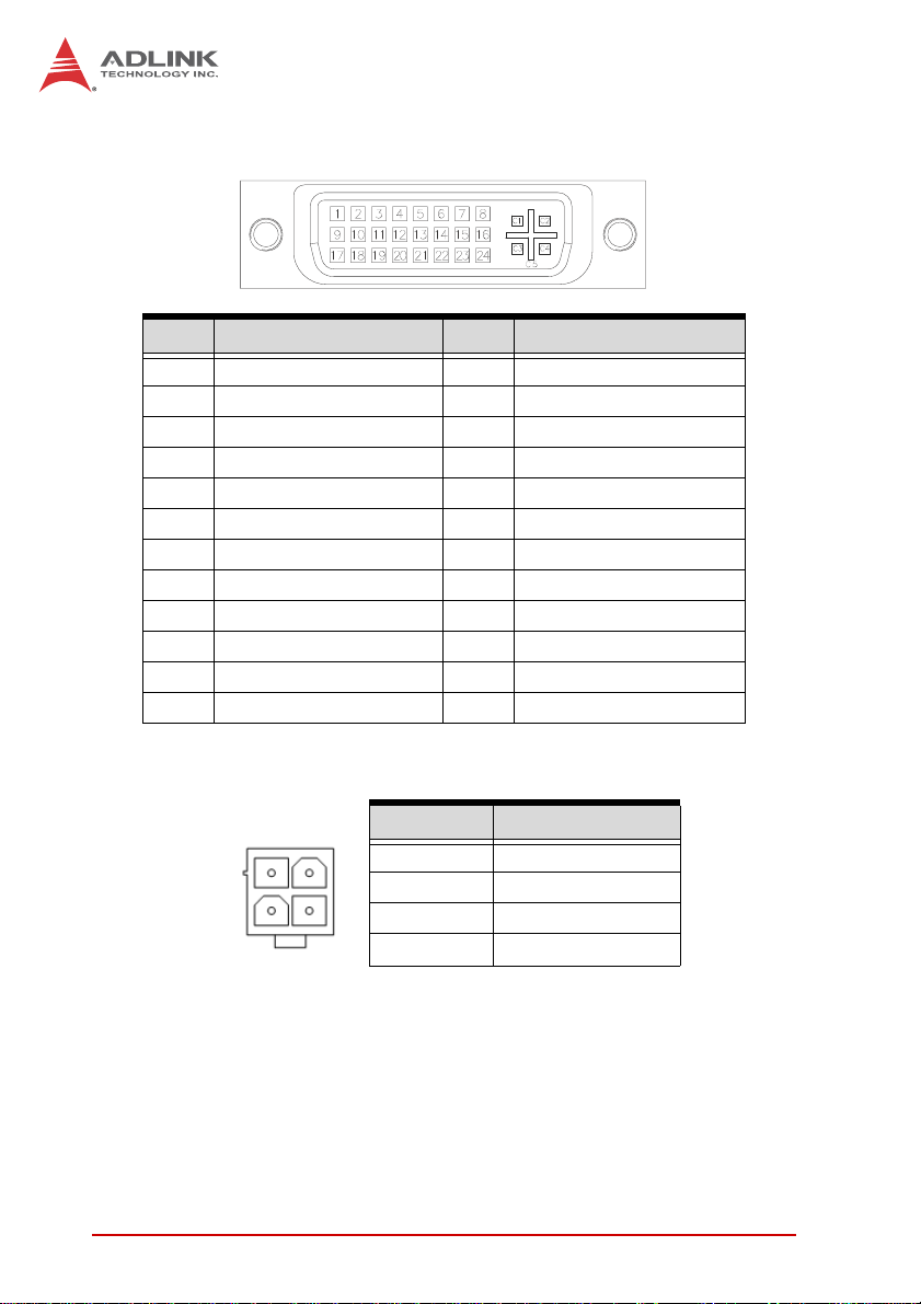
DVI-D Bracket Connector
(optional cable w/ bracket, P/N 30-01052-2000)
Pin # Signal Pin # Signal
1 TMDS Data2- 13 TMDS Data3+
2 TMDS Data2+ 14 +5 V Power
3 TMDS Data2/4 Shield 15 GND
4 TMDS Data4- 16 Hot Plug Detect
5 TMDS Data4+ 17 TMDS Data06 DDC Clock [SCL] 18 TMDSData0+
7 DDC Data [SDA] 19 TMDS Data0/5 Shield
8 Analog vertical sync 20 TMDS Data5-
9 TMDS Data1- 21 TMDS Data5+
10 TMDS Data1+ 22 TMDS Clock Shield
11 TMDS Data1/3 Shield 23 TMDS Clock +
12 TMDS Data3- 24 TMDS Clock -
This page intentionally left blank.
ATX 12V Power Connector (CN24)
Pin # Signal
2
4
14 Introduction
1
3
1GND
2GND
3 +12V DC
4
+12V DC
Page 27
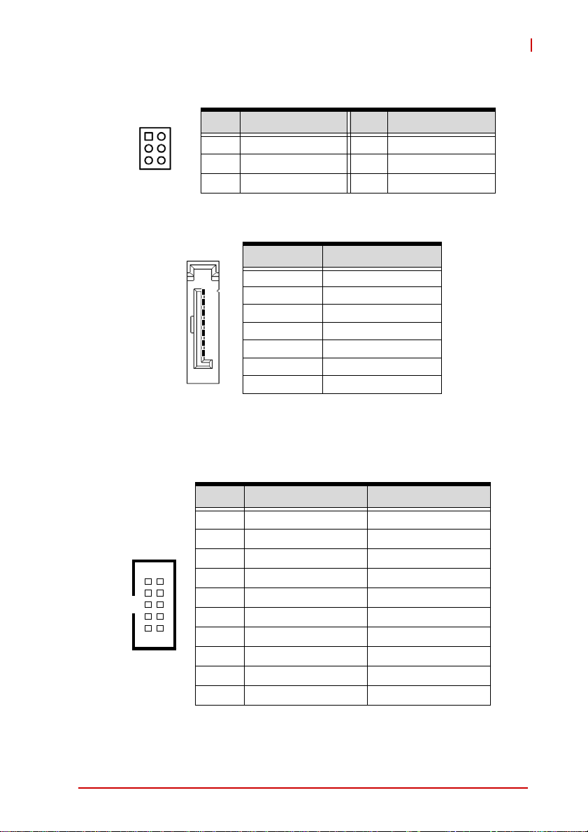
PS/2 Keyboard/Mouse Pin Header (CN27)
NuPRO-E42
1
2
1 KBDATA 2 KBCLK
3 MSDATA 4 MSCLK
5 KM_VCC 6 GND
Serial ATA Connectors (CN30~33)
Pin # Signal Pin # Signal
Pin # Signal
1GND
1
2TXP
3TXN
4GND
7
5RXN
6RXP
7GND
HD Audio Daughter Board Connector (CN40)
This connector is designed for use with the ADLINK DB-Audio2
daughter board.
Pin # Signal Function
1 GND Ground
2 AUD_BCLK Audio Clock
3 GND Ground
12
910
4 ICH_AUD_SDIN1 Audio Data Input
5 P5V + 5V
6 ICH_AUD_SDOUT Audio Data Output
7 P5V_AUD + 5V
8 P3V3_DVDD 3.3V
9 AUD_SYNC Audio Synchronous
10 AUD_RSTJ Audio Reset
Introduction 15
Page 28
System Panel Connector (CN45)
Connects to chassis-mounted buttons, speakers, and LEDs.
Pin # Signal Function Pin Group
1 WDSPK Speaker signal
1
10 20
2NC
3NC
4+5V Power
5NC
6 GND Ground
11
7 KEYLOCK Keyboard lock
8 PLED Power LED signal
9NC
10 +5V Power LED pull-up
11 GND Ground
12 RESETBT RESET signal
13 NC
14 GND Ground
15 POWERBT Power-on signal
16 NC
17 NC
18 HDDLED Hard Disk LED signal
19 +3.3V Hard Disk LED pull-up
20 NC
Chassis Speaker
Power LED
Reset Button
Power Button
Key Lock
HDD LED
Fan Connectors (FAN1/2)
Pin # Signal
1GND
14
16 Introduction
2 Fan power (+12V)
3 Fan Tachometer
Fan Speed Control
4
Page 29

NuPRO-E42
1.11 Jumpers & Switches
Clear CMOS Jumper (JBAT1)
To clear the BIOS settings (RTCRTS# asserts):
1. Power down and disconnect power from the system.
2. Short pins 2-3 on JP1.
3. Reconnect power and power up the system.
4. Wait 3 seconds or more.
5. Power down and disconnect power from the system.
6. Re-short pins 1-2, and power up the system..
CMOS Status Connection JBAT1
Normal 1 – 2
Clear CMOS 2 – 3
Clear RTC Jumper (JBAT2)
To clear the BIOS settings and data/time (SRTCRST# and
RTCRST# assert):
1. Power down and disconnect power from the system.
2. Short pins 2-3 on JP1.
3. Reconnect power and power up the system.
After power up, remove the jumper ca p from pins 2-3 and reinstall it to pins 1-2.
CMOS Status Connection JBAT2
Normal 1 – 2
Clear CMOS 2 – 3
To clear CMOS, clear both CMOS and RTC jumpers at the same
time.
Introduction 17
Page 30

COM1 Mode Switch (SW13)
ON
ON
1
1 2
DIP #1 DIP #2 COM1 Mode
On Off RS-232
On On RS-422
Off On RS-485
3
2
1.12 Power Consumption
Intel® Core™ i7-4770S, 3.1 GHz, 8M Cache, 65W TDP (4C)
Test Configuration
Memory Transcend TS1GLK64V6H DDR3-1600 8GB x2
Graphics Integra ted Intel® HD Grap hics
SATA Channel 1 ALDINK ASD26-MLC32G-CT
Power Supply FSP FSP350-60PFG 350W
BIOS Rev. 0.91
Mode
S1
S3 129mA / 5VSB 0.645 0.645
Current (A) /
Voltage (V)
0.86A / 12V 10.32
0.78A / 3.3V 2.574
Power (W) Total (W)
15.0440.43A / 5V 2.15
S5 81mA / 5VSB 0.405 0.405
18 Introduction
Page 31

NuPRO-E42
Mode
Idle Load
CPU Max
Max. Load
Table 1-3: Core™ i7-4770S Processor Power Consu mption
Current (A) /
Voltage (V)
0.38A / 12V 4.56
0.78A / 3.3V 2.574
6.53A / 12V 78.36
0.77A / 3.3V 2.541
6.50A / 12V 78
0.78A / 3.3V 2.574
Power (W) Total (W)
10.5340.68A / 5V 3.4
85.1510.85A / 5V 4.25
86.3241.15A / 5V 5.75
Intel® Core™ i5-4330S, 2.7 GHz, 3M Cache, 54W TDP (2C)
T est Configuration
Memory Transcend TS1GLK64V6H DDR3-1600 8GB x2
Graphics Integrated Intel® HD Graphics
SATA Channel 1 ALDINK ASD26-MLC32G-CT
Power Supply FSP FSP350-60PFG 350W
BIOS Rev. 0.91
Mode
S1
S3 169mA / 5VSB 0.845 0.845
S5 103mA / 5VSB 0.515 0.515
Idle Load
Introduction 19
Current (A) /
Voltage (V)
0.99A / 12V 11.88
0.51A / 3.3V 1.683
0.45A / 12V 5.4
0.65A / 3.3V 2.145
Power (W) Total (W)
15.8130.45A / 5V 2.25
10.7950.65A / 5V 3.25
Page 32

Mode
CPU Max
Max. Load
Table 1-4: Core™ i5-4430S Processor Power Consumption
Current (A) /
Voltage (V)
3.61A / 12V 43.32
0.66A / 3.3V 2.178
3.80A / 12V 45.6
0.65A / 3.3V 2.145
Power (W) Total (W)
49.5480.81A / 5V 4.05
54.3951.33A / 5V 6.65
1.13 Package Contents
Before unpacking, check the shipping carton for any damage. If
the shipping carton and/or contents are damaged, inform your
dealer immediately. Retain the shipping carton and packing
materials for inspection. Obtain authorization from the dealer
before returning any product to ADLINK.
X NuPRO-E42
X SATA data cable with latch x2
X 2-port USB 3.0 cable with bracket
X 2-port COM cable with bracket for COM1/COM2
(2.54 mm pitch)
X 2-port COM cable with bracket x2 for COM3-6
(2.0 mm pitch)
X Driver DVD
X User’s manual
The NuPRO-E42 must be protected from static discharge and
physical shock. Never remove any of the socketed parts except
WARNING:
20 Introduction
at a static-free workstation. Use the anti-static bag shipped with
the product to handle the board. Wear a grounded wrist strap
when installing and/or servicing.
Page 33

2 Getting Started
2.1 Installing the CPU
The NuPRO-E 42 supports an Intel® Core™ i7/i5 /i3 or Penti um®
processor in an LGA1150 socket.
X Disconnect all power to the board before
installing a CPU to prevent damaging the
WARNING:
To install the CPU:
1. Press down on the locking arm (A), then push it away from
the socket to disengage it from the retention tab (B).
board and CPU.
X Do not touch socket con tacts. Damaging the
contacts voids the product warranty. Follow the
installation instructions carefully to avoid damaging the board components.
A
NuPRO-E42
B
2. Raise the locking arm to unlock the load plate.
Getting Started 21
Page 34

3. Lift the load plate to uncover the socket.
4. Remove the plastic protective cover from the socket.
Note the locations of the alignment keys (A) and Pin 1
indicator (B).
B
A
Do NOT touch socket contacts.
WARNING:
5. Hold the CPU using thumb and forefinger as shown.
Position the CPU over the socket, m atching the no tches
on the sides of the CPU with the alignment keys on the
socket (A). The golden triangle on the CPU must be
positioned at the corner of the socket with the Pin 1 indi-
22 Getting Started
Page 35

cator as shown (B).
AB
The CPU fits into the socket in only one orientation. DO NOT
force it into the socket to avoid causing damage.
WARNING:
6. Carefully place the CPU into the socket vertically. The
socket has cutouts for your fingers to fit into.
NuPRO-E42
Cutouts
Getting Started 23
Page 36

7. Gently lower the load plate. Make sure the front edge of
the plate is under the screw as indicated.
8. Lower the locking arm and fasten it to the retention tab
(A). The load plate should be locked underneath the
screw as shown (B).
B
A
24 Getting Started
Page 37

NuPRO-E42
2.2 Installing the CPU Fan and Heatsink
The CPU requires a chassis with an airflow inlet and maximum
internal ambient temperature of 50° C. A especially-designed
WARNING:
CPU fan and heatsink must be installed before using the SHB.
Failure to install a CPU fan and heatsink may damage the system host board and/or the CPU..
If CPU fan installation procedures presented here are inconsistent
with the installation procedures you obtained from the CPU fan
and heatsink package, follow the latter.
To install the CPU fan:
1. Apply thermal grease evenly on top of the installed CPU.
2. Lower the CPU fan to the CPU, then secure it using the
provided attachments or screws.
3. Connect the CPU fan cable to the CPU fan connector on
the SHB labeled FAN2.
2.3 Installing Memory Modules
The NuPRO-E42 supports up to 16 GB of DDR3 1333/1600 MHz
memory modules in two DIMM sockets. A DDR3 module has a
240-pin footprint compared to the legacy 184-pin DDR DIMM.
DDR3 modules are notched to facilitate correct installation in the
DIMM sockets.
Disconnect all power to the board before installing a memory
module to prevent damaging the board and memory module.
WARNING:
Getting Started 25
Page 38

Memory Configuration Options
The NuPRO-E42 supports 1GB, 2GB, 4GB and 8GB unbuffered
non-ECC DDR3 DIMMs in the following configurations:
X Channel A: DIMM1
Channel B: DIMM2
X For dual-channel configuration, the total size of memory
module installed per channel must be the same
(DIMM1 = DIMM2).
X It is recommended that you install DIMMs with the same
CAS latency. For maximum compatibility, install memory
modules with the same brand, model, and/or rating.
To install a memory module:
1. Locate the DIMM sockets on the motherboard.
2. Press the socket’s retaining clips outward to unlock.
3. Align the memory module on the socket making sure
that the notch matches the break on the socket.
26 Getting Started
Page 39

NuPRO-E42
Notch
Break
4. Insert the module firmly into the slot until the retaining
clips snap back inwards and the module is securely
seated.
2.4 Driver Installation
This chapter provides information on how to install the NuPROE42 device drivers under Windows 7 64-bit. The device drivers are
located in the following ADLINK All-in-One DVD directories:
Chipset \NuPRO\NuPRO-E42\Chipset\
Display \NuPRO\NuPRO-E42\VGA\
Ethernet \NuPRO\NuPRO-E42\Ethernet\
Rapid Storage \NuPRO\NuPRO-E42\Others\RST\
USB 3.0 \NuPRO\NuPRO-E42\Others\
Getting Started 27
Page 40

Management
Engine
\NuPRO\NuPRO-E42\Others\ME_Driver\
Install the Windows operating system before installing any driver.
Most standard I/O device drivers are installed during Windows
installation.
In order to enable RAID or AHCI mode, you must pre-install the
Intel® Rapid Storage Technology driver during the Windows* instal-
WARNING:
lation process. using the F6 installation method.
*Not required for Windows Vista and Windows 7.
2.4.1 Intel® Q87 Express Chipset Driver
This section describes the installa tion of the Intel® Q87 Express
chipset driver.
1. Locate the directory X:\NuPRO\NuPRO-E42\Chipset\
on the ADLINK All-in-One DVD, run the program
infinst_autol.exe and follow the onscreen instructions.
Restart the system if prompted.
2.4.2 Display Driver
Integrated Intel® HD Graphics
This section describes the driver installation for the Integrated
Intel® HD Graphics.
Follow these instructions to install the display driver:
1. Locate the directory X:\NuPRO\NuPRO-E42\VGA\64
Bit\ on the ADLINK All-in-One DVD, and extract the contents of the following archive: Win64.zip
2. Run the program setup.exe and follow the onscreen
instructions. Restart the system if prompted.
2.4.3 Ethernet Driver
Follow these instructions to install the Ethernet driver.
1. Locate the directory
X:\NuPRO\NuPRO-E42\Ethernet\Windows\64\ on the
ADLINK All-in-One DVD, run the program PROWinx64.exe
28 Getting Started
Page 41

NuPRO-E42
and follow the onscreen instructions. Restart the system if
prompted.
2.4.4 Management Engine
Follow these instructions to install the Management Engine driver.
1. Locate the directory
X:\NuPRO\NuPRO-E42\Others\ME_Driver\ on the ADLINK
All-in-One DVD, and extract all files from the following
archive: ME90.zip.
2. Run the program setup.exe and follow the onscreen
instructions. Restart the system if prompted.
2.4.5 USB 3.0 Driver
Follow these instructions to install the USB 3.0 driver.
1. Locate the directory
X:\NuPRO\NuPRO-E42\USB3\ on the ADLINK All-inOne DVD, and extract all files from the following archive:
USB3.zip.
2. Run the program setup.exe and follow the onscreen
instructions. Restart the system if prompted.
Getting Started 29
Page 42

This page intentionally left blank.
30 Getting Started
Page 43

Appendix A BIOS Setup
The following chapter describes basic navigation for the
AMIBIOS® EFI BIOS setup utility.
A.1 Starting the BIOS
To enter the setup screen, follow these steps:
1. Power on the motherboard
2. Press the < Delete > key on your keyboard when you
see the following text prompt:
< Press DEL to run Setup >
3. After you press the < Delete > key, the main BIOS setup
menu displays. You can access the other setup screens
from the main BIOS setup menu , such as Chipset and
Power menus.
In most cases, the < Delete > key is used to invoke the setup
screen. There are several cases that use other keys, such as <
NOTE:
NOTE:
F1 >, < F2 >, and so on.
NuPRO-E42
Setup Menu
The main BIOS setup menu is the first screen that you can navigate. Each main BIOS setup menu option is described in this
user’s guide.
The Main BIOS setup menu screen has two main frames. The left
frame displays all the options that can be configured. “Grayed”
options cannot be configured, “Blue” options can be.
The right frame displays the key legend. Above the key legend is
an area reserved for a text message. When an option is selected
31
Page 44
in the left frame, it is highlighted in white. Often a text message will
accompany it.
Navigation
The BIOS setup/utility uses a key-based navigation system called
hot keys. Most of the BIOS setup utility hot keys can be used at
any time during the setup navigation process.
These keys include < F1 >, < F10 >, < Enter >, < ESC >, < Arrow >
keys, and so on. .
32
Page 45

NuPRO-E42
Note: There is a hot key legend located in the right frame on most
setup screens.
There is a hot key legend located in the right frame on
NOTE:
NOTE:
most setup screens.
.
The < F8 > key on your keyboard is the Fail-Safe key. It is not displayed on the key legend by default. To set the Fail-Safe settings
of the BIOS, press the < F8 > key on your keyboard. It is located
on the upper row of a standard 101 keyboard. The Fail-Safe settings allow the motherboard to boot up with the least amount of
options set. This can lessen the probability of conflicting settings.
Hotkey Descriptions
F1 The < F1 > key allows you to display the General Help
screen.
Press the < F1 > key to open the General Help screen.
33
Page 46

F10 The < F10 > key allows yo u to save any changes you have
made and exit Setup. Press the < F10 > key to save your
changes. The following screen will appear:
Press the < Enter > key to save the configuration and exit.
You can also use the < Arrow > key to select Cancel and
then press the < Enter > key to abort this functio n and return
to the previous screen.
ESC The < Esc > key allows you to discard any changes you have
made and exit the Setup. Press the < Esc > key to exit the
setup without saving your changes. The following screen will
appear:
Press the < Enter > key to discard changes and exit. You can
also use the < Arrow > key to select Cancel and then press
the < Enter > key to abort this function and return to the previous screen.
Enter The < Enter > key allows you to display or change the setup
option listed for a particular setup item. The < Enter > key
can also allow you to display the setup sub-screens.
34
Page 47

NuPRO-E42
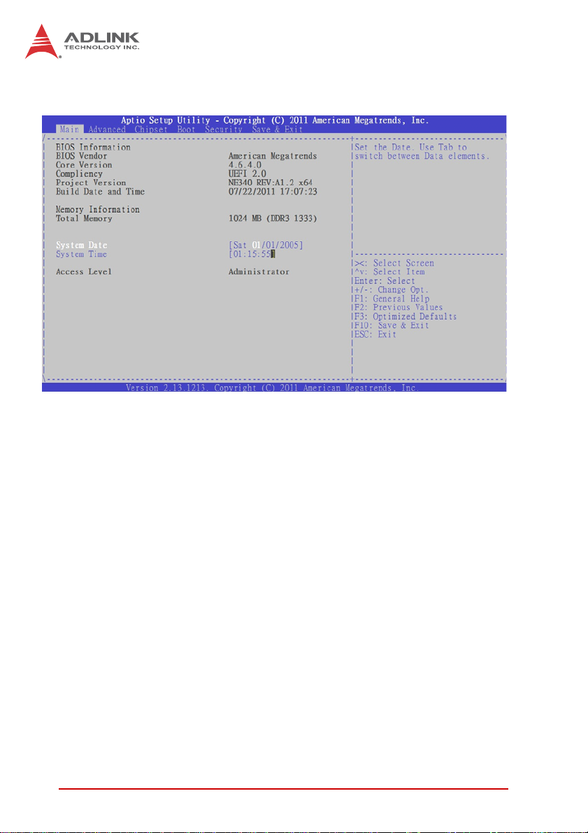
A.2 Main Setup
When you first enter the Setup Utility, you will enter the Main setup
screen. You can always return to the Main setup screen by selecting the Main tab. There are two Main Setup options. They are
described in this section. The Main BIOS Setup screen is shown
below.
System & Board Info
BIOS Vendor
Displays the BIOS vendor.
Core Version
Displays the BIOS core version.
Compliancy
Displays the current BIOS compliancy.
Project Version
Displays the current BIOS revision.
Build Date and Time
Displays the BIOS build data.
35
Page 48

System Time/System Date
Use this option to change the system time and date. Highlight System Time or System Date using the < Arrow > keys. Enter new values using the keyboard. Press the < Tab > key or the < Arrow >
keys to move between fields. The date must be entered in MM/
DD/YY format. The time is entered in HH:MM:SS format.
Note: The time is in 24-hour format. For example, 5:30 A.M. ap-
pears as 05:30:00, and 5:30 P.M. as 17:30:00.
Access Level
Displays the current system access level.
A.3 Advanced BIOS Setup
Select the Advanced tab from the setup screen to enter the
Advanced BIOS Setup screen. You can select any of the items in
the left frame of the screen, such as SuperIO Configuration, to go
to the sub menu for that item. You can display an Advanced BIOS
Setup option by highlighting it using the < Arrow > keys. The
Advanced BIOS Setup screen is shown below.
The sub menus are described on the following pages.
36
Page 49

Launch PXE OpROM
Boot Option for Legacy Network Devices. Options: Enabled/
Disabled.
A.3.1 ACPI Settings
Enable APIC Auto Configuration
BIOS ACPI Auto Configuration. Options: Enabled/Disabled.
Enable Hibernation
Enable or disable the system's ability to hibernate (S4 sleep
state). This option may be not effective with some OS's.
NuPRO-E42
ACPI Sleep State
Select the highest ACPI sleep state the system will enter , when
the SUSPEND button is pressed. Options: S1, S3, Suspend
Disable.
AC Power Shutdown
ATX mode: OS will turn off system power when shutdown.
AT mode: OS show It is now safe to turn off your computer.
AT mode will not support S3 & S4.
NOTE:
NOTE:
Lock Legacy Resources
Enable or disable Lock of Legacy Resources.
37
Page 50

A.3.2 Trusted Computing
Trusted computing is an industry standard to make personal computers more secure through a dedicated hardware chip, called a
Trusted Platform Module (TPM).
TPM Support
This option enables or disables the TPM support. System reset
is required. Options: Enabled/Disabled.
TPM State
Determine whether TPM state change requires Password
Authentication. Options: Enabled/Disabled.
Pending TPM Operation
Scheduled TPM operation. The settings for this value are
Enable, Disable and Clear.
38
Page 51

A.3.3 CPU Configuration
Active Processor Cores
NuPRO-E42
Number of cores to enable in processor. Options: All, 1, 2.
Limit CPUID Value Maximum
When Enabled, the processor will limit the maximum CPUID
input value to 03h when queried, even if the processor supports a higher CPUID input value. When Disabled, the processor will return the actual maximum CPUID input value of the
processor when queried. Enable this option to allow compatibility with older operating systems.
Execute Disable Bit
Allows you to enable or disable the No-Execution Page Protection Technology. Setting this item to [Disabled] forces the XD
feature flag to always return a zero (0). Options: Enabled, Disabled.
Intel® Virtualization Tech
When enabled, Intel® Virtualization Technology (Intel® VT)
makes a single system appear as multiple independent sys-
39
Page 52

tems to software. This allows for multiple, independent operating systems to be running simultaneously on a single system.
Power Technology
Sets the power management features. Options: Disable,
Energy Efficient, Custom.
40
Page 53

Socket 0 CPU Information
A.3.4 SATA Configuration
NuPRO-E42
41
Page 54

SATA Mode
Options: IDE, RAID, AHCI.
Serial ATA Controller 0/1
Appears when SATA mode is set to IDE. This item specifies
whether Serial ATA Controller 0/1 is initialized in Compatible or
Enhanced mode of operation. The settings are Disabled, Compatible and Enhanced.
Aggressive Link Power Management
Appears when SA TA mode is set to AHCI. The settings are Disabled and Enabled.
SATA Port 0~5
The Staggered Spin-up, External SATA Port (eSATA) and
Hot Plug options appear when SATA Mode is set to AHCI.
Options: Enabled/Disabled.
A.3.5 Intel TXT Configuration
Intel Trusted Execution Technology (Intel TXT) support can only
be enabled when TPM is enabled, if the CPU supports Safer Mode
42
Page 55

NuPRO-E42
Extensions (SMX), and Intel® Virtualization Technology (Intel®
VT) and Intel® Virtualization Technology for Directed I/O (VT-d)
are enabled.
A.3.6 Intel IGD SWSCI OpRegion
DVMT Mode
This item allows the user to enable or disable the DVMT function.
DVMT/Fixed Memory
Select DVMT/Fixed memory size used by the Integrated
Graphics Device. Options: 128MB, 256MB, Maximum.
IGD - Boot Type
Select the video device which will be activated during POST.
This has no effect if an external graphics device is present.
Options: CRT+DVI, CRT, DVI.
Spread Spectrum Clock
IGD device spread spectrum clock function. Options: Enabled/
Disabled.
43
Page 56

A.3.7 USB Configuration
Legacy USB Support
Legacy USB Support refers to USB mouse and keyboard support. Normally if this option is not enabled, any attached USB
mouse or USB keyboard will not become available until a USB
compatible operating system is fully booted with all USB drivers loaded. When this option is enabled, any attached USB
mouse or USB keyboard can control the system even when
there are no USB drivers loaded on the system. Set this value
to enable or disable the Legacy USB Support.
X Disabled: Set this value to prevent the use of any USB
device in DOS or during system boot.
X Enabled: Set this value to allow the use of USB devices
during boot and while using DOS.
X Auto: This option auto detects USB Keyboards or Mice and
if found, allows them to be utilized during boot and while
using DOS.
USB 3.0 Support
USB 3.0 Controller support. Options: Enable, Disable.
44
Page 57

NuPRO-E42
XHCI Hand-Off
This is a workaround for OSes without XHCI hand-off support.
The XHCI ownership change should be claimed by XHCI
driver. Op tions: Enable, Disable.
EHCI Hand-Off
This is a workaround for OSes without EHCI hand-off support.
The EHCI ownership change should be claimed by EHCI
driver. Op tions: Enable, Disable.
All USB Devices
Enabled/Disabled All USB devices. Options: Enable, Disable.
EHCI Controller 1/2
Enabled/Disabled USB 2.0 (EHCI) Support. Options: Enable,
Disable.
USB Port 0~13
Enabled/Disabled USB Port 0~13. Options: Enable, Disable.
Mass Storage Devices:
Mass storage device emulation type. 'AUTO' enumerates
devices according to their media format. Optical drives are
emulated as 'CDROM', drives with no media will be emulated
according to a drive type. Options: Auto, Floppy, Forced FDD,
Hard Disk, CD-ROM.
45
Page 58

A.3.8 Super IO Configuration
Serial Port1-6 Configuration
Enter the submenu for each serial port to enable/disable and
view the I/O port and IRQ settings.
Parallel Port Configuration
Enter the submenu to enable/disable the parallel port and
specify the base I/O port address.
46
Page 59

NuPRO-E42
A.3.9 Hardware Monitor
You can use this screen to view System Status information and to
select options for FAN1 settings (FAN2
is set to Full On by default
).
Smart Fan 1 Mode Setting
Three operating modes are provided for FAN1: Full Mode, Auto-
matic Mode, and Manual Mode. Full Mode runs the fan at full
speed. Automatic Mode is Smart Fan mode. Manual Mode runs
the fan at the set speed (minimum is 0, maximum is 127).
Automatic Mode
In Automatic Mode, the following settings are visible.
Fan Off Temperature Limit
Sets the temperature below which the fan will turn off in
degrees Celsius (°C). When the temperature is higher than the
set value, FAN1 will run at Fan Start PWM speed. When the
temperature is lower than the set value, FAN1 will stop.
Fan Start Temperature Limit
47
Page 60

When the temperature in degrees (°C) is higher than the set
value, FAN1 will increase its speed according to the PWM
Slope Setting value.
Fan Start PWM
Sets the PWM value of the fan between Fan Off Temperature
Limit and Fan Start Temperature Limit. Minimum value is 0
and maximum is 127.
PWMSlope Setting
The Slope PWM Value sets the rate of increase the fan speed
when the temperature is above Fan Start Temperature Limit.
System Status
System temperature, CPU temperature and fan speed (FAN1),
system voltages.
A.3.10 AMT Configuration
AMT
This item allows the user to Enable/Disable the Intel AMT function.
48
Page 61

Unconfigure AMT/ME
This item allows the user to unprovision th e AMT/ME function
without a password.
WatchDog Timer
Options: Enabled/Disabled.
OS WatchDog Timer
Sets the OS WatchDog Timer (seconds).
BIOS WatchDog Timer
Sets the BIOS WatchDog Timer (seconds).
A.3.11 Serial Port Console Redirection
NuPRO-E42
COM0/1 Console Redirection
Options: Enabled/Disabled.
49
Page 62

Console Redirection Settings
The settings specify how the host computer and the remote
computer exchange data. Both computers should have the
same or compatible settings.
Terminal Type
This option is used to select either VT100/VT-UTF8 or ANSI
terminal type. Options: VT100, VT100+, VT-UTF8, ANSI.
Bits per second
Select the bits per second you want the serial port to use for
console redirection. The options are 115200, 57600, 38400,
19200, 9600.
Data Bits
Select the data bits you want the serial port to use for console
redirection. Set this value to 7 and 8.
Parity
Set this option to select Parity for console redirection. The settings for this value are None, Even, Odd, Mark and Space.
Stop B its
Stop bits indicate the end of a serial data packet. (A start bit
indicates the beginning). The standard setting is 1 stop bit.
Communication with slow devices may require more than 1
stop bit. Set this value to 1 and 2.
50
Page 63

NuPRO-E42
Flow Control
Set this option to select Flow Control for console redirection.
The settings for this value are None, Hardware RTS/CTS.
Record Mode
With this mode enabled only text will be sent., allowing capture
of Terminal data. Set this value to Enabled or Disabled.
Resolution 100x31
Enable or disable extended terminal resolution. Set this value
to Enabled or Disabled.
Legacy OS Redirection Resolution
On a legacy OS, the number of Rows and Columns supported
by redirection. Set this value to 80x24 and 80x25.
Serial Port for Out-of-Band Management
These settings control the ACPI serial port redirection table
(SPCR) which is used by Windows servers to provide Windows
Emergency Management Services (EMS) and is independent
from console redirection output. OoB Management or EMS
allows the remote management of selected components of
51
Page 64

Windows servers, even when a server is not connected to the
network or the network is not available
Terminal Type
VT-UTF8 is the preferred terminal type for out-of-band management. The next best choice is VT100+ and then VT100.
See above, in Console Redirection Settings page, for more
Help with Terminal Type/Emulation. Options: VT100, VT100+,
VT-UTF8, ASNI.
Bits per second
Select the bits per second you want the serial port to use for
console redirection. The options are 115200, 57600, 38400,
19200, 9600.
Flow Control
Set this option to select Flow Control for console redirection.
The settings for this value are None, Hardware RTS/CTS.
Data Bits
Displays the frame width for Out-of-Band Management.
52
Page 65

NuPRO-E42
Parity
Displays the parity for Out-of-Band Management.
Stop B its
Displays the number of stop bits for Out-of-Band Management.
A.4 Chipset Setup
Select the Chipset tab from the setup screen to enter the Chipset
BIOS Setup screen. You can select any of the items in the left
frame of the screen to go to the sub m enu for t hat it em. T he C hipset BIOS Setup screen is shown below.
53
Page 66

A.4.1 Graphics and Memory Bridge Configuration
VT-d
Intel Virtualization Technology for Directed I/O. Options: Enabled/
Disabled.
Initial Graphics Adapter
Allows you to select which graphics controller to use as the primary boot device. Options: IGD, PCI/IGD, PCI/PEG, PEG/IGD,
PEG/PCI.
IGD Memory
IGD shared memory size, Options: Disable/32M/64M/128M.
IGD Multi-Monitor
Multi-monitor support by the Internal Graphics Device. Options:
Enabled/Disabled
PCI Express Port
This option enables auto negotiation with a PEG device, disables
the use of the PEG port, or select enables use of the PEG port
54
Page 67

A.4.2 PCH Bridge Configuration
82574L LAN Controller
Controls the onboard Intel 82574L LAN controller. Options:
Enabled/Disabled.
Restore on AC Power Loss
Determines which state the computer enters when AC power is
restored after a power loss. The options for this value are Last
State, Power On and Power Off.
NuPRO-E42
X Power Off: Set this value to always power off the system
while AC power is restored.
X Power On: Set this value to always power on the system
while AC power is restored.
X Last State: Set this value to power off/on the system depend-
ing on the last system power state while AC power is restored.
ALC626 HD Audio
Set this value to Enable/Disable the HD Audio Controller.
55
Page 68

PCI Express Port Configuration
PCI Express Port 1~8
Configures the PCI Express ports in of the chipset. Options: Auto,
Enable, Disable.
PCIe Sub Decode
Enable or disable the PCIe Sub Decode port. This option is available when the Subtractive Decode Agent is enable (PCH T r ap9[14])
= '1b'.
PCIE Ports 0-3 Configuration
Use this option to configure PCIe ports 0-3 of the PCH to "One x4
Port" or "Four x1 Ports".
56
NOTE:
NOTE:
The PCIE Ports 0-3 Configuration option is available in
BIOS version A1.6 and later.
Page 69

A.4.3 Management Engine Subsystem
ME Subsystem
Options: Enabled/Disabled.
NuPRO-E42
ME Temporary Disable
Options: Enabled/Disabled (reset required).
End of POST Message
Options: Enabled/Disabled.
Execute MEBx
Options: Enabled/Disabled.
MEBx Mode
Options: Normal, Hidden Ctrl+P, Enter MEBx setup.
57
Page 70

Integrated Clock Chip Configuration
ICC Enable
Integrated Clock Chip. Options: Enabled/Disabled.
A.5 Boot Configuration
Select the Boot tab from the setup screen to enter the Boot BIOS
Setup screen. You can select any of the items in the left frame of
the screen, such as Boot Device Priority, to go to the sub menu for
that item. You can display a Boo t BIOS setup option b y highlight-
58
Page 71

NuPRO-E42
ing it using the < Arrow > keys. The Boot Configuration screen is
shown below:
Setup Prompt Timeout
Number of seconds to wait for setup activation. 65535
(0xFFFF) means wait indefinitely.
Bootup NumLock State
This setting determines the state of t he NumLock function on
bootup. Options: On, Off.
Quiet Boot
When this feature is enabled, the BIOS will display the fullscreen logo during the boot-up sequence, hiding normal POST
messages.
When it is disabled, the BIOS will display the normal POST
messages, instead of the full-screen logo.
Gate A20 Active
Options: Upon Request, Always.
59
Page 72

Boot Option Priorities
Set the boot device options to determine the sequence in which
the computer checks which device to boot from.
Hard Drive BBS Priorities
The Boot devices are listed in groups by device type. First
press <Enter> to enter the sub-menu. You may then use the
arrow keys to select the desired device, then press <+>, <-> or
<PageUp>, <PageDown> key to move it up/down in the priority
list. For example, USB storage disks will be listed as "USB
Drives" in the sub-menu. Only the first device in each device gr
A.6 Security Setup
Password Support
Two Levels of Password Protection
Provides both a Supervisor and a User password. If you use
both passwords, the Supervisor password must be set first.
The system can be configured so that all users must enter a
password every time the system boots or when Setup is exe-
60
Page 73

cuted, using either or either the Supervisor password or User
password.
The Supervisor and User passwords activate two different levels of password security. If you select password support, you
are prompted for a one to six character password. Type the
password on the keyboard. The password does not appear on
the screen when typed. Make sure you write it down. If you forget it, you must drain NVRAM and re-configure.
Remember the Password
Keep a record of the new password when the password is
changed. If you forget the password, you must erase the system configuration information in NVRAM.
To access th e su b m e nu for the following items, select the item
and press < Enter >:
X Change Administrator Password
X Change User Password
X Clear User Password
Administrator Password
NuPRO-E42
Indicates whether a Administrator password has been set.
User Password
Indicates whether a user password has been set.
A.7 Exit Menu
Select the Exit tab from the setup screen to enter the Exit BIOS
Setup screen. You can display an Exit BIOS Setup option by high-
61
Page 74

lighting it using the < Arrow > keys. The Exit BIOS Setup screen is
shown below.
Save Changes and Exit
When you have completed the system configuration changes,
select this option to leave Setup and reboot the computer so the
new system configuration parameters can take effect.
Save Configuration Changes and Exit Now?
[Ok] [Cancel]
appears in the window. Select Ok to save changes and exit.
62
Page 75

NuPRO-E42
Discard Changes and Exit
Select this option to quit Setup without making any permanent
changes to the system configuration.
Discard Changes and Exit Setup Now?
[Ok] [Cancel]
appears in the window. Select Ok to discard changes and exit.
Save Changes and Reset
Reset the system after saving the changes.
Discard Changes and Reset
Reset system setup without saving any changes.
Save Changes
Save changes made so far to any of the setup options.
Discard Changes
Select Discard Changes from the Exit menu and press < Enter >.
Select OK to discard changes.
Restore Defaults
Restore/Load Default values for all the setup options.
Save as User Defaults
Save the changes made so far as User Defaults.
Restore User Defaults
Restore the User Defaults to all the setup options.
Boot Override
This group of functions includes a list of devices within the boot
order. Select a drive to immediately boot that device regardless of
63
Page 76

the current boot order. If you are booting to the EFI Shell, an exit
from the shell returns to Setup.
64
Page 77

Appendix B - Watchdog Timer
A sample program for configuring the NuPRO-E42’s watchdog
timer is included on the ADLINK All-in-One DVD in the following
directory: \NuPRO\NuPRO-E42\WDT.
B.1 Sample Code
#include<stdio.h>
#include<dos.h>
static unsigned int IT8783_ioPort = 0x2e;
void Enter_IT8783_Config(unsigned int flag)
{
if(flag) IT8783_ioPort = 0x4e;
switch(IT8783_ioPort)
{
case 0x2E: //Address port = 0x2E, enter keys =
0x87, 0x01, 0x55, 0x55
outportb(0x2E, 0x87);
outportb(0x2E, 0x01);
outportb(0x2E, 0x55);
outportb(0x2E, 0x55);
break;
case 0x4E: //Address port = 0x4E, enter keys =
0x87, 0x01, 0x55, 0xAA
outportb(0x4E, 0x87);
outportb(0x4E, 0x01);
outportb(0x4E, 0x55);
outportb(0x4E, 0xAA);
break;
default:
break;
}
}
NuPRO-E42
void Exit_IT8783_Config(unsigned int flag)
{
if(flag) IT8783_ioPort = 0x4e;
outportb(IT8783_ioPort, 0x02);
outportb(IT8783_ioPort+1, 0x02);
Watchdog Timer 65
Page 78

}
void Get_IT8783_ID(unsigned int &ID1, unsigned int &ID2)
{
outportb(IT8783_ioPort, 0x20);
ID1 = inportb(IT8783_ioPort+1);
outportb(IT8783_ioPort, 0x21);
ID2 = inportb(IT8783_ioPort+1);
}
void IT8783_WDTRun(unsigned int count_value, unsigned int
PLEDflag) //for NuPRO-E42
{
unsigned long tempCount;
unsigned int registerValue;
outportb(IT8783_ioPort, 0x07);
outportb(IT8783_ioPort+1, 0x07);// Device 7
outportb(IT8783_ioPort, 0xf8);
outportb(IT8783_ioPort+1, 0x00);// PLED mapping to
nothing, disable PLED function
if(PLEDflag == 1)
{
outportb(IT8783_ioPort, 0x27);
registerValue = inportb(IT8783_ioPort + 1);
registerValue |= 0x80; // set Pin09 is GPIO
function GP37
outportb(IT8783_ioPort+1, registerValue);
outportb(IT8783_ioPort, 0xc2);
registerValue = inportb(IT8783_ioPort + 1);
registerValue &= 0x7fb; // set GP37 is alternate
function
outportb(IT8783_ioPort+1, registerValue);
outportb(IT8783_ioPort, 0xca);
registerValue = inportb(IT8783_ioPort + 1);
registerValue |= 0x80; // set GP42 is output
outportb(IT8783_ioPort+1, registerValue);
66 Watchdog Timer
Page 79

outportb(IT8783_ioPort, 0xf8);
outportb(IT8783_ioPort+1, 0x1f);// PLED mapping to
GP37
outportb(IT8783_ioPort, 0xf9);
registerValue = inportb(IT8783_ioPort + 1);
registerValue |= 0x02;
registerValue &= 0xfb;
outportb(IT8783_ioPort+1, registerValue);
}
outportb(IT8783_ioPort, 0x71);
registerValue = inportb(IT8783_ioPort + 1);
registerValue &= 0xfe;
outportb(IT8783_ioPort+1, registerValue);
outportb(IT8783_ioPort, 0x72);
registerValue = inportb(IT8783_ioPort + 1);
registerValue &= 0xdf;
outportb(IT8783_ioPort+1, registerValue);
if(count_value >= 60)
{
outportb(IT8783_ioPort, 0x72);
registerValue = inportb(IT8783_ioPort+1);
registerValue &= 0x8f;
registerValue |= 0x40; //enable WDT output through
PRST
outportb(IT8783_ioPort+1, registerValue); // set
WDT count is minute
NuPRO-E42
tempCount = count_value / 60;
if((count_value%60) > 30)
tempCount++;
if(tempCount > 65535)
tempCount = 65535;
printf("WDT timeout in %d minutes.\n", tempCount);
}
else
{
outportb(IT8783_ioPort, 0x72);
Watchdog Timer 67
Page 80

registerValue = inportb(IT8783_ioPort+1);
registerValue |= 0x80;
tempCount = count_value;
if(tempCount != 0)
{
printf("WDT timeout in %d seconds.\n",
tempCount);
registerValue |= 0x40; //Enable WDT output
through KBRST
}
else
{
printf("WDT is Disabled.\n");
registerValue &= 0xbf; //Disable WDT output
through KBRST
}
outportb(IT8783_ioPort+1, registerValue); // set
WDT count is second
}
outportb(IT8783_ioPort, 0x71);
registerValue = inportb(IT8783_ioPort + 1);
registerValue |= 0x60; // set Mouse & Keyboard
interrupt Enable
outportb(IT8783_ioPort+1, registerValue);
outportb(IT8783_ioPort, 0x73);
outportb(IT8783_ioPort+1, tempCount); // set WDT count
LSB
}
68 Watchdog Timer
Page 81

Appendix C - System Resources
C.1 System Memory Map
NuPRO-E42
Address Range
(decimal)
(4GB-2MB)
(4GB-18MB) –
(4GB-17MB-1)
(4GB-20MB) –
(4GB-19MB-1)
960 K – 1024 K F0000 – FFFFF 64 KB System BIOS Area
896 K – 960 K E0000 – EFFFF 64 KB Extended System BIOS Area
768 K – 896 K C0000 – DFFFF 128 KB
640 K – 768 K A000 0 – BFFF F 128 KB Video Buffer & SMM space
0 K – 640 K 00000 – 9FFFF 640 KB DOS Area
Address Range
(hex)
FFE00000 –
FFFFFFFF
FEE00000 –
FEEFFFFF
FEC00000 –
FECFFFFF
Table C-1: System Memory Map
Size Description
2 MB High BIOS Area
1 MB FSB Interrupt Memory Space
1 MB APIC Configuration Space
PCI expansion ROM area
C0000 – C7FFF: Onboard VGA BIOS
CB800 – CC7FFF: Intel 82577LM
PXE option ROM when onboard LAN
boot ROM is enabled.
C.2 Direct Memory Access Channels
Channel Number Data Width System Resource
08-bits
18-bits
28-bits
38-bits
4 Reserved - cascade channel
5 16-bits Open
6 16-bits Open
7 16-bits Open
Parallel port
Parallel port
Diskette drive
Parallel port
(1)
(1)
(1)
(1)
Table C-2: Direct Memory Access Channels
Note (1): DMA channel 0, 1, or 3 will be occupied when using the parallel port.
System Resources 69
Page 82

C.3 IO Map
Hex Range Device
000-01F DMA controller 1, 8237A-5 equivalent
020-02D and 030-03F Interrupt controller 1, 8259 equivale nt
02E-02F,04 E -04F LPC SIO (ITE8783) configuration index/data registers
040-042, 050-052 Timer, 8254-2 equivalent
060, 062, 064, 066 8742 equivalent (keyboard)
061 NMI control and status
070-077 Real Time Clock Controller (bit 7 -NMI mask)
080-091 DMA page register
092 Reset (Bit 0)/ Fast Gate A20 (Bit 1)
093-09F DMA page registers continued
0A0-0B1 and 0B4-0BD Interrupt controller 2, 8259 equivalent
0C0-0DF DMA controller 2, 8237A-5 equivalent
0F0
2E0 - 2F7 Serial Port 6
2E8 – 2EF Serial Port 4
2F0 – 2F7 Serial Port 5
2F8 – 2FF Serial Port 2
170-177 and 1F0-1F7
376 and 3F6
378 - 37F Parallel port
3B0 – 3BB Mono/VGA mode video
3C0- 3DF VGA registers
3E8 – 3EF Serial Port 3
3F8 – 3FF Serial Port 1
4D0 and 4D1 Interrupt controller
400 – 47F SB PM Base Address
500 – 57F SB GPIO
A00 – A3F SIO PME Base Address
CF9 Reset Control register (8 bit I/O)
1180 – 119F SMBus
Read: PCI and Master abort. (Note 1)
Write: FERR#/ IGNNE# /Interrupt controller
SATA controller or PCI
Table C-3: IO Map
Note:
A read to this address will subtractively go to PCI, where it will master abort.
70 System Resources
Page 83

C.4 Interrupt Request (IRQ) Lines
IRQ Lines PIC Mode
NuPRO-E42
IRQ#
0 Counter 0 N/A No
1 Keyboard controller N/A No
2
3 Serial Port 2 (COM2)
4
5 PCI / ISA
6N/A N/A No
7 PCI / ISA
8 Real-time clock N/A No
9 SCI / PCI
10 PCI / ISA N/A No
11 PCI / ISA N/A No
12 PS/2 Mouse / PCI / ISA
13 Math Processor N/A No
14
15 PCI / ISA N/A No
Typical Interrupt
Resource
Cascade interrupt from
slave PIC
Serial Port 1 (COM1) /
PCI / ISA
Primary IDE controller /
PCI / ISA
Connected to Pin Available
N/A No
IRQ3 via SERIRQ, IRQ3
at ISA bus
IRQ4 via SERIRQ, IRQ4
at ISA bus
IRQ5 via SERIRQ, IRQ5
at ISA bus
IRQ7 via SERIRQ, IRQ7
at ISA bus
IRQ9 via SERIRQ, IRQ9
at ISA bus
IRQ12 via SERIRQ,
IRQ12 at ISA bus
IRQ14 via SERIRQ,
IRQ14 at ISA bus
Note (1)
Note (1)
Note (1)
Note (1)
Note (1), (2)
Note (1)
Note (1)
Table C-4: IRQ Lines PIC Mode
Notes:
(1) These IRQs can be used for PCI devices when the onboard device
is disabled. If the IRQ is from ISA, the user must reserve the IRQ for
ISA in the BIOS setup menu.
(2) The BIOS does not open the IRQ 9 setting for the ISA bus.
System Resources 71
Page 84

IRQ Lines APIC Mode
IRQ#
0 System Timer N/A No
1 Keyboard controller N/A No
2 PCI / ISA N/A No
3
4
5
6
7
8 Real-time clock N/A No
9 ACPI-Compliant system
10 PCI / ISA
11 Serial Port 6 /PCI / ISA
12 PS/2 Mouse / PCI / ISA
13 Math Processor N/A No
14
15
16 N/A
17 N/A
T ypical Interrupt
Resource
Serial Port 2 (COM2) /
PCI / ISA
Serial Port 1 (COM1) /
PCI / ISA
Serial Port 3 (COM3) /
PCI / ISA
Serial Port 4 (COM4) /
PCI / ISA
Parallel Port / Serial
5 (COM5) / PCI / ISA
Primary IDE controller /
PCI / ISA
Secondary IDE
controller / PCI / ISA
Port
Connected to Pin Available
IRQ3 via SERIRQ,
IRQ3 at ISA bus
IRQ4 via SERIRQ,
IRQ4 at ISA bus
IRQ5 via SERIRQ,
IRQ5 at ISA bus
IRQ6 via SERIRQ No
IRQ7 via SERIRQ,
IRQ7 at ISA bus
IRQ9 via SERIRQ,
IRQ9 at ISA bus
IRQ10 via SERIRQ,
IRQ10 at ISA bus
IRQ11 via SERIRQ,
IRQ11 at ISA bus
IRQ12 via SERIRQ,
IRQ12 at ISA bus
IRQ14 via SERIRQ,
IRQ14 at ISA bus
IRQ15 via SERIRQ,
IRQ15 at ISA bus
PCIE Port 0/1/2/3/4/5/6/7,
P.E.G. Root Port, I.G.D,
EHCI Controller #2,
MEI Controller.
PCIE Port 0/1/2/3/4/5/6/7,
P.E.G. Root Port, KT Controller
Note (1)
Note (1)
Note (1)
Note (1)
Note (1), (2)
Note (1)
Note (1)
Note (1)
Note (1)
Note (1)
Yes
Yes
72 System Resources
Page 85

NuPRO-E42
IRQ#
18 N/A
19 N/A
20 N/A
21 N/A PCI Slot 0, PCI Slot 4 No
22 N/A PCH HDA, PCI Slot 1 No
23 N/A EHCI Controller #1, PCI Slot 2 No
Typical Interrupt
Resource
Ta b le C-5: IRQ Lines AP IC Mode
Notes:
(1) These IRQs can be used for PCI devices when the onboard device
is disabled. If the IRQ is from ISA, the user must reserve the IRQ for
ISA in the BIOS setup menu.
(2) The BIOS does not open the IRQ 9 setting for the ISA bus.
Connected to Pin Available
PCIE Port 0/1/2/3/4/5/6/7,
P.E.G. Root Port, SATA Host
controller, SMBus Controller,
Thermal Controller,
SOL (COM7)
PCIE Port 0/1/2/3/4/5/6/7,
P.E.G. Root Port, SATA Host
controller, SATA Host
controller#1,
PCH internal GBE controller,
PCI Slot 3
Yes
Yes
No
System Resources 73
Page 86

PCI Configuration Space Map
Bus # Device # Function # Routing Description
00h 00h 00h N/A Intel Host Bridge
00 02H 00H Internal Intel IG D
02 00H 0FFH N/A P.E.G. Port
00h 02h 00h Internal
00h 16h 00h Internal
00h 16h 01h Internal
00h 16h 02h Internal IDE-R controller
00h 16h 03h Internal PCI Serial controller
00h 19h 00h Internal GbE Controller
00h 1Ah 00h Internal Intel USB EHCI Controller #2
00h 1Bh 00h Internal High Definition Audio controlle r
00h 1Ch 00h Internal PCI Express Root port 1
00h 1Ch 01h Internal PCI Express Root port 2
00h 1Ch 02h Internal PCI Express Root port 3
00h 1Ch 03h Internal PCI Express Root port 4
00h 1Ch 04h Internal PCI Express Root port 5
00h 1Ch 05h Internal PCI Express Root port 6
00h 1Ch 06h Internal PCI Express Root port 7
00h 1Ch 07h Internal PCI Express Root port 8
00h 1Dh 00h Internal Intel USB EHCI Controller #1
00h 1Eh 00h N/A Intel PCI to PCI Bridge
00h 1Fh 00h N/A Intel LPC Interface Bridge
00h 1Fh 02h Internal Intel SATA controller #1
00h 1Fh 03h Intern al Intel SMBus Controller
00h 1Fh 05h Internal Intel SATA controller #2
00h 1Fh 06h Internal Thermal Controller
11h 00h 0FFh Internal PCIE Port #0
12h 00h 0FFh Internal PCIE Port #1
13h 00h 0FFh Internal PCIE Port #2
Intel Integrated Graphics
Device
Intel Management Engine
Interface #1
Intel Management Engine
Interface #2
74 System Resources
Page 87

NuPRO-E42
Bus # Device # Function # Routing Description
14h 00h 0FFh Internal PCIE Port #3
15h 00h 0FFh Internal Intel 82574L LAN Controller
16h 00h 0FFh Internal PCIE Port #5
17h 00h 0FFh Internal USB 3.0 Controller
18h 00h 0FFh Internal PCIE Port #7
20h 0Fh 00h Internal PCI Slot 0
20h 0Eh 00h Internal PCI Slot 1
20h 0Dh 00h Internal PCI Slot 2
20h 0Ch 00h Internal PCI Slot 3
20h 0Bh 00h Internal PCI Slot 4
Table C-6: PCI Configuration Space Map
System Resources 75
Page 88

PCI Interrupt Routing Map
PIRQ A B C D E F G H
INT Line INTA INTB INTC INTD
P.E.G. Root Port INTA INTB INTC INTD
VGA X
SATA Controller X X
SATA Controller 1 X
SMBus controller X
Thermal Controller X
EHCI 1 X
EHCI 2 X
HDA X
Intel GBE X
HECI host 1 X
HECI host 2 X
IDER Controller X
KT Controller X
PCIE port 0 INTA INTB INTC INTD
PCIE port 1 INTB INTC INTD INTA
PCIE port 2 INTC INTD INTA INTB
PCIE port 3 INTD INTA INTB INTC
PCIE port 4 INTA INTB INTC INTD
PCIE port 5 INTB INTC INTD INTA
PCIE port 6 INTC INTD INTA INTB
PCIE port 7 INTD INTA INTB INTC
PCI Slot 0 X
PCI Slot 1 X
PCI Slot 2 X
PCI Slot 3 X
PCI Slot 4 X
Table C-7: PCI Interrupt Routing Map
76 System Resources
Page 89

NuPRO-E42
Important Safety Instructions
For user safety, please read and follow all instructions,
WARNINGS, CAUTIONS, and NOTES marked in this manual
and on the associated equipment before handling/operating the
equipment.
X Read these safety instructions carefully.
X Keep this user’s manual for future reference.
X Read the specifications section of this manual for detailed
information on the operating environment of this equipment.
X When installing/mounting or uninstalling/removing
equipment:
Z Turn off power and unplug any power cords/cables.
X To avoid electrical shock and/or damage to equipment:
Z Keep equipment away from water or liquid sources;
Z Keep equipment away from high heat or high humidity;
Z Keep equipment properly ventilated (do not block or
cover ventilation openings);
Z Make sure to use recommended voltage and power
source settings;
Z Always install and operate equipment near an easily
accessible electrical socket-outlet;
Z Secure the power cord (do not place any object on/over
the power cord);
Z Only install/attach and operate equipment on stable
surfaces and/or recommended mountings; and,
Z If the equipment will not be used for long periods of time,
turn off and unplug the equipment from its power source.
Important Safety Instructions 77
Page 90

X Never attempt to fix the equipment. Equipment should only
be serviced by qualified personnel.
A Lithium-type battery may be provided for uninterrupted, backup
or emergency power.
Risk of explosion if battery is replaced with one of an incorrect
WARNING:
type. Dispose of used batteries appropriately.
X Equipment must be serviced by authorized technicians
when:
Z The power cord or plug is damaged;
Z Liquid has penetrated the equipment;
Z It has been exposed to high humidity/moisture;
Z It is not functioning or does not function according to the
user’s manual;
Z It has been dropped and/or damaged; and/or,
Z It has an obvious sign of breakage.
78 Important Safety Instructions
Page 91

Getting Service
Contact us should you require any service or assistance.
ADLINK Technology, Inc.
Address: 9F, No.166 Jian Yi Road, Zhonghe District
New Taipei City 235, Taiwan
ᄅקؑխࡉ৬ԫሁ 166 ᇆ 9 ᑔ
Tel: +886-2-8226-5877
Fax: +886-2-8226-5717
Email: service@adlinktech.com
Ampro ADLINK Technology, Inc.
Address: 5215 Hellyer Avenue, #110
San Jose, CA 95138, USA
Tel: +1-408-360-0200
Toll Free: +1-800-966-5200 (USA only)
Fax: +1-408-360-0222
Email: info@adlinktech.com
ADLINK Technology (China) Co., Ltd.
Address: Ϟ⍋Ꮦ⌺ϰᮄᓴ∳催⾥ᡔು㢇䏃 300 ো(201203)
300 Fang Chun Rd., Zhangjiang Hi-Tech Park
Pudong New Area, Shanghai, 201203 China
Tel: +86-21-5132-8988
Fax: +86-21-5132-3588
Email: market@adlinktech.com
NuPRO-E42
ADLINK Technology Beijing
Address: ࣫ҀᏖ⍋⎔Ϟഄϰ䏃 1 োⲜ߯ࡼ E ᑻ 801 ᅸ(100085)
Beijing, 100085 China
Tel: +86-10-5885-8666
Fax: +86-10-5885-8626
Email: market@adlinktech.com
ADLINK Technology Shenzhen
Address: ⏅ഇᏖቅ⾥ᡔು催ᮄϗ䘧᭄ᄫᡔᴃು
Tel: +86-755-2643-4858
Fax: +86-755-2664-6353
Email: market@adlinktech.com
LiPPERT ADLINK Technology GmbH
Address: Hans-Thoma-Strasse 11, D-68163
Mannheim, Germany
Tel: +49-621-43214-0
Fax: +49-621 43214-30
Email: emea@adlinktech.com
Rm. 801, Power Creative E, No. 1 Shang Di East Rd.
A1 2 ὐ C (518057)
2F, C Block, Bldg. A1, Cyber-Tech Zone, Gao Xin Ave. Sec. 7
High-Tech Industrial Park S., Shenzhen, 518054 China
Getting Service 79
Page 92

ADLINK Technology, Inc. (French Liaison Office)
Address: 6 allée de Londres, Immeuble Ceylan
91940 Les Ulis, France
Tel: +33 (0) 1 60 12 35 66
Fax: +33 (0) 1 60 12 35 66
Email: france@adlinktech.com
ADLINK Technology Japan Corporation
Address: 〒101-0045 東京都千代田区神田鍛冶町 3-7-4
Tel: +81-3-4455-3722
Fax: +81-3-5209-6013
Email: japan@adlinktech.com
ADLINK Technology, Inc. (Korean Liaison Office)
Address: 137-881 서울시 서초구 서초대로 326, 802 (서초동, 모인터빌딩)
Tel: +82-2-2057-0565
Fax: +82-2-2057-0563
Email: korea@adlinktech.com
ADLINK Technology Singapore Pte. Ltd.
Address: 84 Genting Lane #07-02A, Cityneon Design Centre
Tel: +65-6844-2261
Fax: +65-6844-2263
Email: singapore@adlinktech.com
ADLINK Technology Singapore Pte. Ltd. (Indian Liaison Office)
Address: #50-56, First Floor, Spearhead Towers
Malleswaram, Bangalore - 560 055, India
Tel: +91-80-65605817, +91-80-42246107
Fax: +91-80-23464606
Email: india@adlinktech.com
神田 374 ビル 4F
KANDA374 Bldg. 4F, 3-7-4 Kanda Kajicho,
Chiyoda-ku, Tokyo 101-0045, Japan
802, Mointer B/D, 326 Seocho-daero, Seocho-Gu,
Seoul 137-881, Korea
Singapore 349584
Margosa Main Road (between 16th/17th Cross)
ADLINK Technology, Inc. (Israeli Liaison Off
Address: 27 Maskit St., Corex Building
PO Box 12777
Herzliya 4673300, Israel
Tel: +972-54-632-5251
Fax: +972-77-208-0230
Email: israel@adlinktech.com
ADLINK Technology, Inc. (UK Liaison Office)
Tel: +44 774 010 59 65
Email: UK@adlinktech.com
ice)
80 Getting Service
 Loading...