


MXE-1300
Table of contents
 Loading...
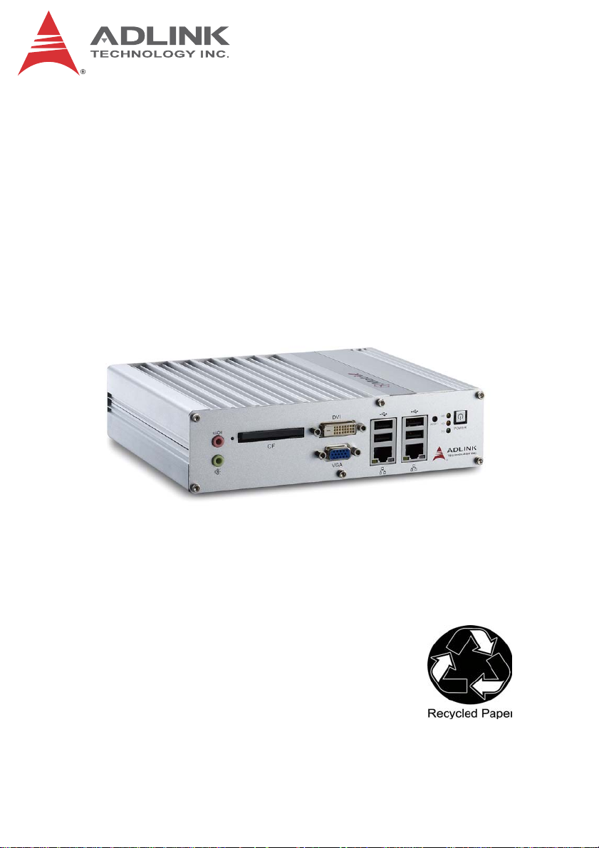
Advance Technologies; Automate the World.
Manual Rev.: 2.00
Revision Date: Sept 28, 2012
Part No: 50-1Z130-2000
MXE-1300 Series
Intel
®
Atom™ D2550/N2600 Fanless
Embedded Computer with Integrated I/O
ii
Revision History
Revision Release Date Description of Change(s)
2.00 Sept 28, 2012 Initital Release

Preface iii
MXE-1300
Preface
Copyright 2012 ADLINK Technology, Inc.
This document contains proprietary information protected by copy-
right. All rights are reserved. No part of this manual may be repro-
duced by any mechanical, electronic, or other means in any form
without prior written permission of the manufacturer.
Disclaimer
The information in this document is subject to change without prior
notice in order to improve reliability, design, and function and does
not represent a commitment on the part of the manufacturer.
In no event will the manufacturer be liable for direct, indirect, spe-
cial, incidental, or consequential damages arising out of the use or
inability to use the product or documentation, even if advised of
the possibility of such damages.
Environmental Responsibility
ADLINK is committed to fulfill its social responsibility to global
environmental preservation through compliance with the Euro-
pean Union's Restriction of Hazardous Substances (RoHS) direc-
tive and Waste Electrical and Electronic Equipment (WEEE)
directive. Environmental protection is a top priority for ADLINK.
We have enforced measures to ensure that our products, manu-
facturing processes, components, and raw materials have as little
impact on the environment as possible. When products are at their
end of life, our customers are encouraged to dispose of them in
accordance with the product disposal and/or recovery programs
prescribed by their nation or company.
Trademarks
Product names mentioned herein are used for identification pur-
poses only and may be trademarks and/or registered trademarks
of their respective companies.
iv Preface
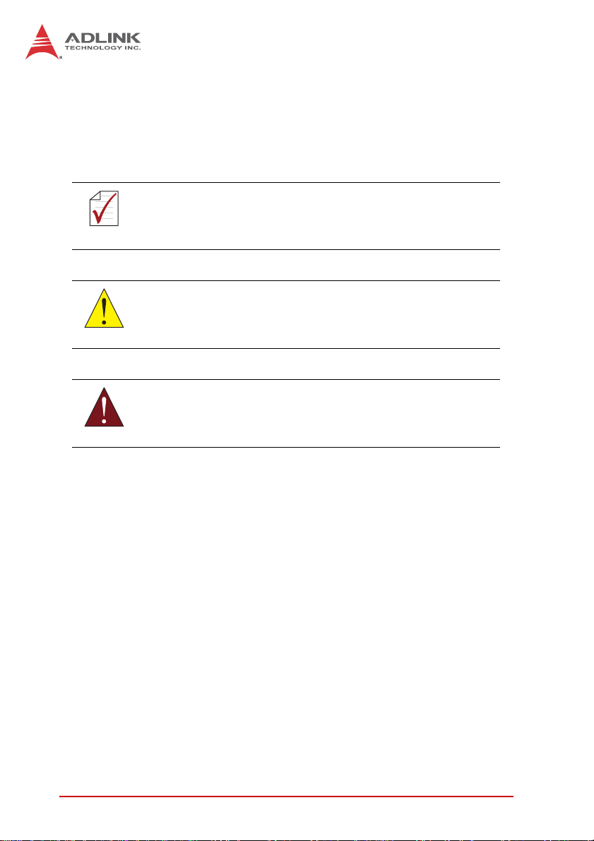
Conventions
Take note of the following conventions used throughout this
manual to make sure that users perform certain tasks and
instructions properly.
NOTE:
NOTE:
Additional information, aids, and tips that help users perform
tasks.
CAUTION:
Information to prevent minor physical injury, component dam-
age, data loss, and/or program corruption when trying to com-
plete a task.
WARNING:
Information to prevent serious physical injury, component
damage, data loss, and/or program corruption when trying to
complete a specific task.

Table of Contents v
MXE-1300
Table of Contents
Revision History...................................................................... ii
Preface.................................................................................... iii
List of Tables.......................................................................... ix
List of Figures........................................................................ xi
1 Introduction ........................................................................ 1
1.1 Overview.............................................................................. 1
1.2 Features............................................................................... 2
1.3 Specifications....................................................................... 3
1.4 Unpacking Checklist ............................................................ 5
1.5 Mechanical Drawings........................................................... 6
1.6 Front Panel I/O Connectors ................................................. 8
1.6.1 Power Button .............................................................. 9
1.6.2 LED indicators ............................................................ 9
1.6.3 Reset Button............................................................. 10
1.6.4 VGA Connector ........................................................ 10
1.6.5 DVI-D Connector ...................................................... 10
1.6.6 USB 2.0 Connectors................................................. 10
1.6.7 Compact-Flash Port.................................................. 10
1.6.8 Gigabit Ethernet (Intel 82574L) ................................ 11
1.6.9 Active/Link & Speed LEDs........................................ 11
1.6.10 MIC & Speaker Jacks ............................................... 12
1.7 Rear Panel I/O Connectors................................................ 13
1.7.1 DC Power Supply Connector.................................... 13
1.7.2 COM Ports................................................................ 14
1.7.3 Digital I/O Connector ................................................ 15
1.7.4 Antenna Connector................................................... 17
1.8 Internal I/O Connectors...................................................... 18

vi Table of Contents
1.8.1 SATA Slot ................................................................. 19
1.8.2 LVDS Interface Connector (optional)........................ 19
1.8.3 Clear CMOS Jumper ................................................ 20
1.8.4 LVDS Backlight Power Connector (option)............... 21
1.8.5 LVDS Voltage Selected Jumper (optional) ............... 22
1.8.6 Mini PCI Express Slot & USIM Socket...................... 22
1.8.7 Extra +3.3 V/ +5 V Voltage Internal Connectors....... 22
1.8.8 Reset/Power Button Extension Internal
Connector ................................................................. 23
2 Getting Started.................................................................. 25
2.1 Installing a Hard Disk Drive................................................ 25
2.2 Installing a CF Card ........................................................... 32
2.3 Connecting DI/O Device .................................................... 33
2.4 Connecting DC power........................................................ 34
2.5 Wall-mounting the MXE-1300 ............................................ 35
2.6 Cooling Configuration ........................................................ 38
3 Driver Installation.............................................................. 39
3.1 Installing the chipset driver ................................................ 39
3.2 Installing the graphics driver .............................................. 40
3.3 Installing the Ethernet driver .............................................. 40
3.4 Installing the audio driver ................................................... 41
3.5 Installing the WDT and DI/O drivers .................................. 41
A Appendix: Watchdog Timer (WDT) &
DI/O Function Libraries..........................................................43
A.1 WDT with API/Windows ..................................................... 43
InitWDT ......................................................................... 43
SetWDT ........................................................................ 44
A.2 DI/O with API/Windows ...................................................... 46
GPIO_Init ...................................................................... 46
GPI_Read() ................................................................... 46

Table of Contents vii
MXE-1300
GPO_Write() ................................................................. 47
GPO_Read() ................................................................. 47
B Appendix: BIOS Setup......................................................49
B.1 Main ................................................................................... 50
B.1.1 BIOS Information ...................................................... 50
B.1.2 PC Health Status ...................................................... 50
B.1.3 System Time/System Date ....................................... 50
B.2 Advanced........................................................................... 51
B.2.1 CPU Configuration.................................................... 52
Hyper-Threading ........................................................... 53
Execute Disable Bit ....................................................... 53
Limit CPUID Maximum ................................................. 53
B.2.2 Onboard Device Configuration ................................. 53
Serial Port 1~4 Configuration ....................................... 54
Intel 82574L LAN #1 ..................................................... 54
Launch Intel 82574 LAN PXE OpROM ......................... 54
Intel 82574L LAN #2 ..................................................... 54
Launch Intel 82574 LAN PXE OpROM ......................... 54
Intel 82574L LAN #3 ..................................................... 54
Launch Intel 82574 LAN PXE OpROM ......................... 54
SATA Controller(s) ........................................................ 54
SATA Mode Selection ................................................... 54
Legacy USB Support .................................................... 55
B.2.3 Advanced Power Management ................................ 55
Restore AC Power Loss ............................................... 55
System Watchdog ......................................................... 56
Wake System With Fixed Time ..................................... 56
Wake On Ring .............................................................. 56
B.2.4 SATA Configuration.................................................. 56
B.2.5 Serial Port Console Redirection ............................... 57
Console Redirection ..................................................... 58

viii Table of Contents
Out-of-Band Mgmt Port ................................................. 58
Terminal Type ............................................................... 58
B.3 Chipset............................................................................... 58
Primary IGFX Boot Display ........................................... 58
Active LFP .................................................................... 59
B.4 Boot ................................................................................... 59
Setup Prompt Timeout .................................................. 59
Bootup Num-Lock State ................................................ 59
Quiet Boot ..................................................................... 59
Fast Boot ...................................................................... 60
Boot Option Priorities .................................................... 60
Hard Drive BBS Priorities ............................................. 60
B.5 Security .............................................................................. 61
Administrator Password ................................................ 61
User Password ............................................................. 61
B.6 Save & Exit ........................................................................ 62
Discard Changes and Exit ............................................ 62
Save Changes and Reset ............................................. 62
Discard Changes .......................................................... 62
Restore Defaults ........................................................... 62
Save as User Defaults .................................................. 63
Restore User Defaults .................................................. 63
Launch EFI Shell from filesystem device ...................... 63
Important Safety Instructions............................................... 65
Getting Service...................................................................... 67

List of Tables ix
MXE-1300
List of Tables
Table 1-1: MXE-1300 Front Panel I/O Connector Legend........... 9
Table 1-2: LED Indicators ............................................................ 9
Table 1-3: Active/Link LED ........................................................ 12
Table 1-4: Speed LED ............................................................... 12
Table 1-5: MXE-1300 Rear Panel I/O Connector Legend ......... 13
Table 1-6: D-sub 9P signal name of COM1 & COM2 ports ....... 15
Table 1-7: DI/O Connector Pin Definition .................................. 16
Table 1-8: MXE-1300 Internal I/O Legend................................. 18
Table 1-9: LVDS Interface Connector Pin Definition ................. 20
Table 1-10: Clear CMOS Jumper ................................................ 20
Table 1-11: LVDS Backlight Power Connector
Pin Definition ............................................................ 21
Table 1-12: LVDS Voltage Selected Jumper ............................... 22
Table 1-13: +3.3 V/ +5 V Voltage Internal Connectors
Pin Definition ............................................................ 23
Table 1-14: Reset/Power Button Extension Internal Connector
Pin Definitions........................................................... 24

xList of Tables
This page intentionally left blank.

List of Figures xi
MXE-1300
List of Figures
Figure 1-1: MXE-1300 Functional Block Diagram......................... 5
Figure 1-2: Top View..................................................................... 6
Figure 1-3: Underside View .......................................................... 7
Figure 1-4: Front View .................................................................. 7
Figure 1-5: Rear View ................................................................... 8
Figure 1-6: Side View.................................................................... 8
Figure 1-7: Front Panel I/O ........................................................... 8
Figure 1-8: Active/Link & Speed LEDs........................................ 11
Figure 1-9: Rear Panel I/O.......................................................... 13
Figure 1-10: DI/O Connector Pin Numbering................................ 15
Figure 1-11: DO Schematic .......................................................... 17
Figure 1-12: DI Schematic ............................................................ 17
Figure 1-13: Internal I/O................................................................ 18
Figure 1-14: LVDS Pin Numbering ............................................... 19
Figure 1-15: LVDS Backlight Power Connector
Pin Numbering.......................................................... 21
Figure 1-16: +3.3 V/ +5 V Voltage Internal Connectors
Pin Numbering.......................................................... 23
Figure 1-17: Reset/Power Button Extension Internal Connector
Pin Numbering.......................................................... 24

xii List of Figures
This page intentionally left blank.

Introduction 1
MXE-1300
1 Introduction
1.1 Overview
The Matrix MXE-1300 series is the latest addition to ADLINK’s
Matrix line of embedded computers. Based on the Intel
®
Atom™
D2550/N2600 processor, the MXE-1300 provides excellent com-
puting performance while conserving considerable power.
The three Intel
®
Gigabit Ethernet ports provide abundant support
for a variety of internet/ intranet applications, and four digital inputs
and outputs deliver superior flexibility for inter-device communica-
tion. An internal PCI Express Mini Card socket and the USIM slot
support extension of additional functions, such as wireless con-
nection (3G/WiFi/BT/GPS), video capture, Secure Access Mod-
ules (SAM), and others.
With its ruggedized architecture and rich I/O, the MXE-1300 is the
best choice for industrial automation/ intelligent transportation sys-
tems, facility management, and applications demanding reliability
in harsh environments.

2Introduction
1.2 Features
X Intel
®
Atom™ D2550/N2600 processor + NM10 chipset
X 2X Software-programmable RS-232/422/485 + 2 RS-232
ports
X 3X 1000/100/10 Mbps Ethernet ports, 6 USB 2.0 ports, 4
TTL digital input and output
X 1 external CF slot and 1 internal PCIe Mini Card socket with
USIM slot
X Built-in 6 VDC to 36 VDC wide-range DC power input
X Rugged, -20°C to 70°C fanless operation (w/ industrial
SSD)*
*This option guarantees cold boot of the system at -20°c and oper-
ation with 100% loading at 70°. The industrial solid-state drive
storage option is required
Introduction 3
MXE-1300
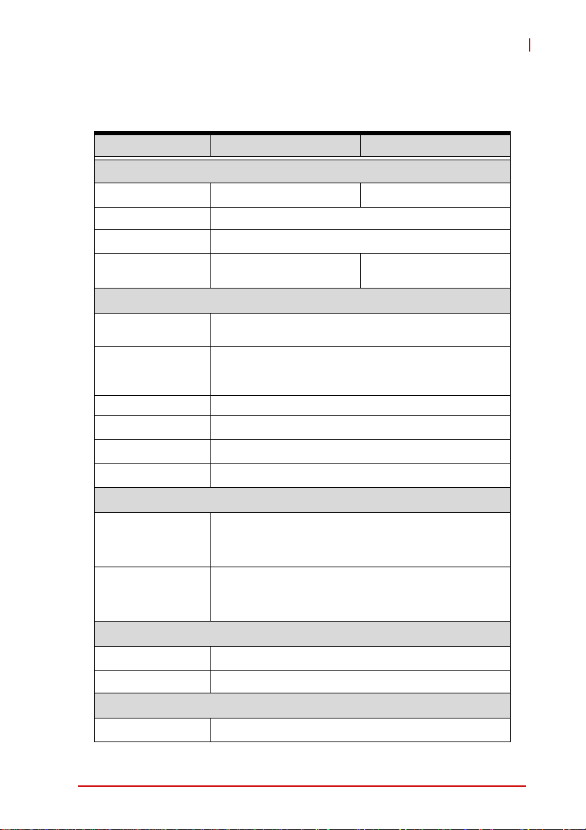
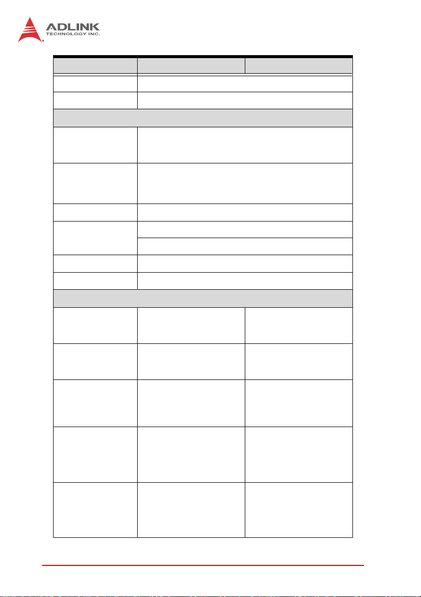
1.3 Specifications
MXE-1301 MXE-1302
System Core
Processor D2550 1.86GHz N2600 1.6GHz
Chipset Intel
®
NM10
Video DVI + VGA dual display up to 1920 x 1200
Memory
Up to 4 GB DDR3
800/1066
Up to 2 GB DDR3 800
I/O Interface
Ethernet 3x GbE ports (3x Intel
®
82574L)
Serial Ports
2x software-programmable RS-232/422/485 (COM1
& COM2)
2x RS-232 (COM3 & COM4)
USB 6x USB 2.0 ports
Audio 1x mic-in and 1x line-out
Expansion
1x mini PCIe slot
DI/O 4DI + 4DO
Power Supply
DC Input
Built-in 6-36 V DC wide-range DC input , 3P
pluggable connector with latch (V-, GND, V+)
AC Input Optional 80 W external AC-DC adapter for AC input
Storage
SATA HDD 1 x onboard SATA port for 2.5" HDD/SSD installation
CF 1x external type I CompactFlash socket
Mechanical
Dimensions 210 (W) x 170 (D) x 53(H) mm (8.3 x 6.75 x 2.1 in.)
4Introduction
Weight 1.8 kg (3.98 lb)
Mounting VESA 100
Environmental
Operating
Temperature
Standard: 0°C to 50°C (32 to 122°F) (w/ HDD)
Extended: -20°C to 70°C (-14 to 140°F) (w/o HDD or
w/ industrial SSD/CF)
Storage
Temperature
-40°C to 85°C (-40 to 185°F)
Humidity approx. 95% @ 40°C (non-condensing)
Vibration
Operating, 5 G, 5-500 Hz, 3 axes (w/ CF or SSD)
Operating, 0.5 G, 5-500 Hz, 3 axes (w/ HDD)
EMC CE, FCC
Shock
Operating, 50 G, half sine 11ms duration (w/ CF or
Power Consumption
Power off 2.16 W
In shutdown status with
DC input and only USB
keyboard/mouse
System Idle 11.04 W
Under Windows Desktop
with no application
programs executed
Processor full load 14/15.8W
Under Windows with
100% CPU utilization
/with 2D/3D graphic full
load
System full load 49.92 W
Under Windows with
100% CPU utilization and
simultaneous access to
all I/O devices.
Recommended
power supply
80W
With consideration of
voltage de-rating under
high environment
temperature.
MXE-1301 MXE-1302
Introduction 5
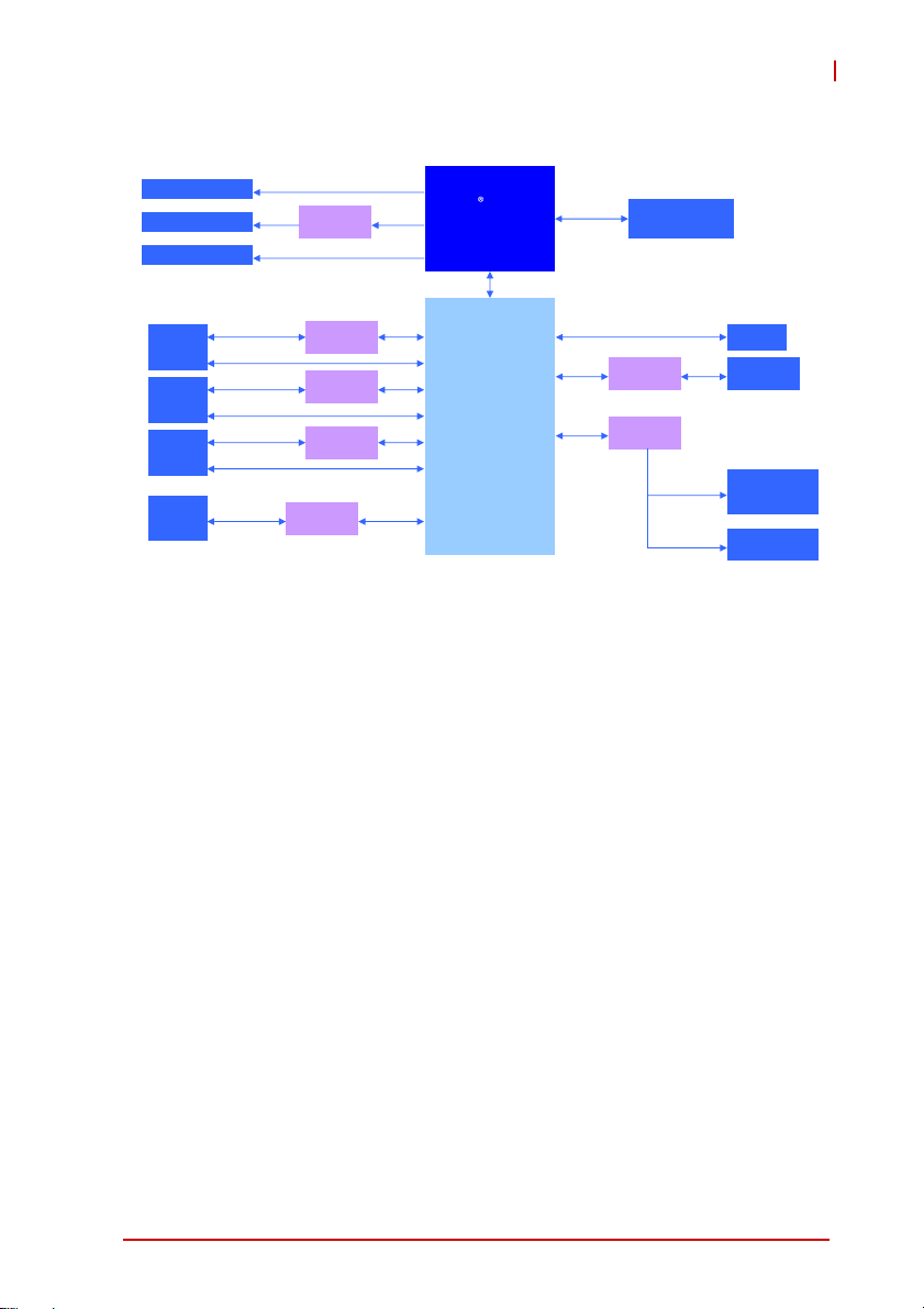
MXE-1300
Figure 1-1: MXE-1300 Functional Block Diagram
1.4 Unpacking Checklist
Before unpacking, check the shipping carton for any damage. If
the shipping carton and/or contents are damaged, inform your
dealer immediately. Retain the shipping carton and packing
materials for inspection. Obtain authorization from your dealer
before returning any product to ADLINK. Ensure that the fol-
lowing items are included in the package.
X MXE-1300
X Screw pack for wall-mounting and HDD installation
X User’s Manual
X ADLINK All-in-One DVD
Intel
Atom
D2550 1.86GHz
Processor
Channel A
204 pin SODIMM
Intel
Ⓡ
NM10
Express Chipset
DDR3
800/1066MHz
DMI
GbE controller
Intel 82574L
RJ45 &
USB x 2
Connector
RJ45 &
USB x 2
Connector
Line out &
Mic in
Jack
COM Port
DB-9
Connector x4
GbE I/F
USB 2.0
Audio
COM serial
PCIe x1
PCIe x1
GbE controller
Intel 82574L
GbE I/F
USB 2.0
Super I/O
LPC
DVI
VGA
DVI-D Connector
DVI
level shifter
SATA
Connector
SATA II
CRT Connector
LVDS Internal Slot
LVDS
SATA
JMD330 CF Card Slot
CF
GbE controller
Intel 82574L
RJ45 &
USB x 2
Connector
GbE I/F
USB 2.0
PCIe x1
Realtek
ALC269Q
HDA
DIO
DIO x4
Connector
Ⓡ
6Introduction
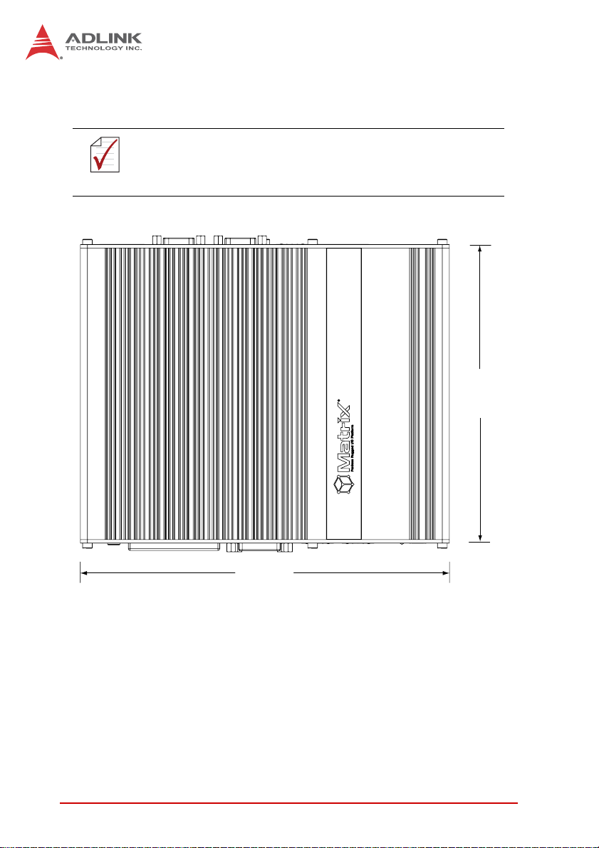
1.5 Mechanical Drawings
Figure 1-2: Top View
NOTE:
NOTE:
All dimensions shown are in millimeters (mm) unless otherwise
stated.
210
170

Introduction 7
MXE-1300
Figure 1-3: Underside View
Figure 1-4: Front View
4x-M4 THREADED
75
75
8Introduction
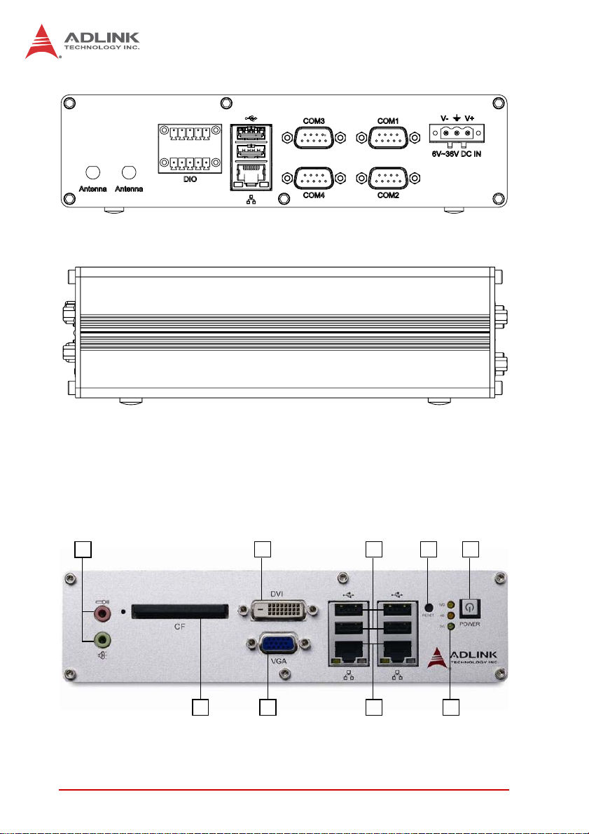
Figure 1-5: Rear View
Figure 1-6: Side View
1.6 Front Panel I/O Connectors
This section describes the I/O connectors lcoated on the front
panel of the MXE-1300.
Figure 1-7: Front Panel I/O
A
B
CD
EF
G
H
I
Introduction 9
MXE-1300
Table 1-1: MXE-1300 Front Panel I/O Connector Legend
1.6.1 Power Button
The power button is a non-latched push button with a blue LED
indicator. System is turned on when button is pressed, and the
power LED lit. To shut down the system, the operating system can
be issued shutdown command in or just press the power button. If
the system halts, press the button for 5 seconds also can turn off
the system compulsorily.
1.6.2 LED indicators
Besides the LED attached in the power button, there are three
LED indicators on the front panel. The following table describes
the color and function of the LED indicators.
T able 1-2: LED Indicators
A Power Button
B LED Indicators
C Reset Button
D USB 2.0 connectors (Type A)
E Gigabit Ethernet connectors
F VGA connector
G DVI connector
H Compact-flash socket
I MIC & speaker jacks
Indicator Color Description
Watchdog (WDT) Yellow
When Watchdog Timer is started,
flashes and lights when timer is expired.
Hard disk drive Red
When the SATA interface device is
active, blinks.
Diagnostic Green
If no physical storage device is
connected to the system, remians lit
If no memory is installed in the
SO-DIMM sockets, blinks.
10 Introduction
1.6.3 Reset Button
The reset button is used to perform hard reset for the MXE-1300.
1.6.4 VGA Connector
The MXE-1300 provides one VGA connector for display on exter-
nal (D-sub 15P) monitor.
1.6.5 DVI-D Connector
The MXE-1300 provides one DVI-D connector for display on an
external (DVI-D) monitor.
1.6.6 USB 2.0 Connectors
The MXE-1300 provides a total of six USB 2.0 ports using Type A
USB connectors, with four ports on the front and two on the rear
panel. All are compatible with Hi-Speed, full-speed, and low-speed
USB devices. All USB ports share one EHCI controller, and two
USB ports share one UHCI controller. The MXE-1300 supports
multiple boot devices, including USB flash drive, USB external
hard drive, USB floppy, USB CD-ROM and etc. The boot priority
and boot device can be configured in BIOS setting.
1.6.7 Compact-Flash Port
The MXE-1300 is equipped with a Type I Compact-Flash socket
on the front panel. The CF interface provides +3.3V voltage to the
CF card, is transferred from SATA by an ASIC, and can act as an
alternative storage device for system installation. The MXE-1300
can be booted up via a CF card with OS installed. When the CF
card is used as the boot device, it must be installed before system
NOTE:
NOTE:
The high impedance of long VGA/DVI cables negatively affects
video signal integrity at the receiver side.
It is recommended that VGA/DVI cables be less than 2
meters in length with effective shielding, such as UL
style 2919 AWM. If video transmission distance is to
exceed 10 meters, a VGA/DVI signal repeater or active
KVM may provide better results.
.
Introduction 11
MXE-1300
powerup. For installation details, see “Installing a CF Card” on
page 32..
1.6.8 Gigabit Ethernet (Intel 82574L)
The MXE-1300 provides two Gigabit Ethernet ports on the front
panel, and one on the rear, via the Intel 82574L controller. The
Ethernet controller supports the following features:
X Advanced error reporting
X Message signaled interrupts
X TCP segmentation offload/large-send support
X 802.3x flow control-compliant
X IEEE 802.1p and 802.1q support
X 10/100/1000 IEEE 802.3-compliant
X Automatic MDI/MDIX crossover at all speeds
X ACPI 2.0 specification
X Wake-On-Link feature
X Preboot eXecution Environment (PXE) flash interface sup-
port
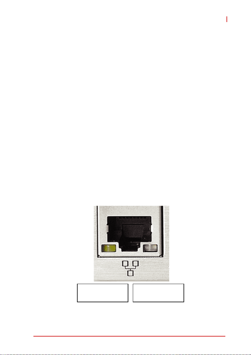
1.6.9 Active/Link & Speed LEDs
Figure 1-8: Active/Link & Speed LEDs
Active/Link LED
Yellow
Speed LED
Green/Orange
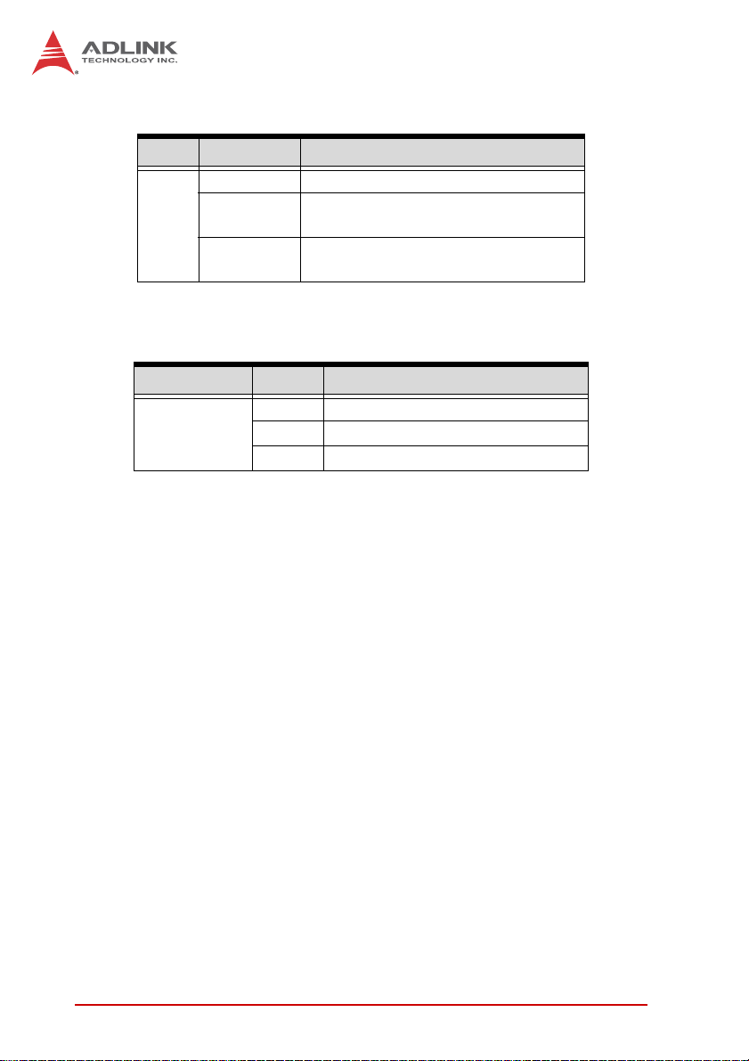
12 Introduction
Table 1-3: Active/Link LED
T able 1-4: Speed LED
1.6.10 MIC & Speaker Jacks
The MXE-1300 implements Intel High Definition audio on the
REALTEK ALC269Q chip, with support up to 24-bit, 192 KHz sam-
ple rate high quality headphone output and microphone input. The
pink jack is for microphone input, and the green jack for head-
phone output.
Color Status Description
Yellow
OFF Ethernet port is disconnected
ON
Ethernet port is connected and no
data transmission is underway
Flashing
Ethernet port is connected and
transmitting/receiving data.
Color St atus Description
Green/Orange
OFF 10 Mbps
Green 100 Mbps
Orange 1000 Mbps
Loading...