


Medical Large Client
MLC 4-xx
Technical Manual Revision 1.2

MLC 4-xx Technical Manual Rev. 1.2 Table of contents
|
1. |
TABLE OF CONTENTS |
|
|
|
||
|
|
|
|
|
|
||
|
1. |
TABLE OF CONTENTS .......................................................................................................... |
|
2 |
|
||
|
|
1.1. |
TABLE OF FIGURES.......................................................................................................... |
|
3 |
||
|
2. |
REVISION HISTORY ............................................................................................................. |
|
4 |
|
||
|
3. |
COMMON INFORMATION ...................................................................................................... |
|
5 |
|
||
|
4. |
USER INFORMATION ........................................................................................................... |
|
6 |
|
||
|
|
4.1. |
GENERAL ....................................................................................................................... |
|
6 |
||
|
|
4.2. |
TRADEMARKS ................................................................................................................. |
|
6 |
||
|
|
4.3. |
WARRANTY INFORMATION................................................................................................ |
|
7 |
||
|
|
4.4. |
SUPPORT, PROBLEMS AND FAILURE ANALYSIS................................................................... |
7 |
|||
|
|
4.5. |
DRIVERS |
........................................................................................................................ |
|
8 |
|
|
|
4.6. |
MAINTENANCE AND SERVICE INTERVALS ........................................................................... |
8 |
|||
|
5. |
SYSTEM OVERVIEW ............................................................................................................ |
|
9 |
|
||
|
|
5.1. |
BLOCK DIAGRAM OF SYSTEM COMPONENTS .................................................................... |
10 |
|||
|
|
5.2. |
TECHNICAL DATA OF SYSTEM COMPONENTS ................................................................... |
10 |
|||
|
|
5.3. |
INTERFACES ................................................................................................................. |
|
11 |
||
|
|
5.4. |
OPTIONS |
...................................................................................................................... |
|
11 |
|
|
6. |
DESCRIPTION OF INTERFACES AND FUNCTIONS ................................................................... |
12 |
||||
|
|
6.1. |
INTERFACES AND CONTROLS ......................................................................................... |
|
12 |
||
|
|
|
6.1.1. |
LOCATION....................................................................................................................... |
|
12 |
|
|
|
|
6.1.2. TABLE OF INTERFACES – TECHNICAL DATA AND INFORMATION............................................ |
13 |
|||
|
|
|
6.1.3. GALVANICALLY ISOLATED COM PORTS ............................................................................ |
14 |
|||
|
|
|
6.1.4. TABLE OF CONTROLS – TECHNICAL DATA AND INFORMATION .............................................. |
15 |
|||
|
|
|
6.1.5. |
EXCHANGING FUSES ....................................................................................................... |
|
15 |
|
|
7. |
BIOS CONFIGURATION OVERVIEW ..................................................................................... |
|
19 |
|||
|
|
7.1. |
DEFAULT SETTINGS ....................................................................................................... |
|
19 |
||
|
|
7.2. |
ENABLE ACPI S3 STATE................................................................................................ |
|
19 |
||
|
|
7.3. |
ENABLE PXE/NETWORK BOOT ....................................................................................... |
|
19 |
||
|
|
7.4. |
CHANGING BOOT DEVICE ORDER .................................................................................... |
20 |
|||
|
8. |
PENTA SOFTWARE.......................................................................................................... |
|
21 |
|||
|
9. |
SPECIFICATIONS .............................................................................................................. |
|
|
22 |
||
|
|
9.1. |
MECHANICAL SPECIFICATIONS MLC 4-21 ....................................................................... |
22 |
|||
|
|
|
9.1.1. DIMENSIONS FRONT AND SIDE VIEW.................................................................................. |
22 |
|||
|
|
|
9.1.2. |
DIMENSIONS REAR VIEW .................................................................................................. |
|
22 |
|
|
|
|
9.1.3. |
WEIGHT.......................................................................................................................... |
|
23 |
|
|
|
9.2. |
ELECTRICAL SPECIFICATIONS......................................................................................... |
|
23 |
||
|
|
|
9.2.1. |
AC INPUT ....................................................................................................................... |
|
23 |
|
|
|
|
9.2.2. POWER CONSUMPTION MLC 4-21 ................................................................................... |
23 |
|||
|
|
9.3. |
ENVIRONMENTAL SPECIFICATIONS.................................................................................. |
24 |
|||
|
|
|
9.3.1. |
IP RATING....................................................................................................................... |
|
24 |
|
|
|
9.4. |
LABELS ........................................................................................................................ |
|
|
24 |
|
|
|
|
9.4.1. |
SERIAL NUMBER LABEL .................................................................................................... |
|
24 |
|
|
|
|
9.4.2. EXPLANATION OF SERIAL NUMBER LABEL SYMBOLS ........................................................... |
25 |
|||
|
|
|
9.4.3. |
FUSE LABEL .................................................................................................................... |
|
25 |
|
|
|
|
|
|
|||
|
Document: Manual_Medical_MLC_1.2 |
Page 2 of 37 pages |
Last change date: 18-Feb-15 |
||||

MLC 4-xx |
Technical Manual Rev. 1.2 |
Table of contents |
|
|
|
|
|
10. |
CLEANING & DESINFECTING .............................................................................................. |
26 |
|
11. |
COMMON WARNINGS, HANDLING AND SAFETY INSTRUCTIONS ............................................... |
28 |
|
12. |
CERTIFICATIONS AND NORMS............................................................................................ |
31 |
|
|
12.1. |
DECLARATION OF CONFORMITY...................................................................................... |
31 |
|
12.2. |
EMC TEST COMPLIANCE................................................................................................ |
32 |
|
|
12.2.1. SUMMARY FOR ALL EMC TESTS....................................................................................... |
32 |
13. |
APPENDIX ....................................................................................................................... |
33 |
|
|
13.1. |
EN 60601-1-2 TABLES .................................................................................................. |
33 |
13.1.1.GUIDANCE AND MANUFACTURER’S DECLARATION – ELECTROMAGNETIC EMISSIONS (IEC
60601-1-2:2007 TABLE 1).............................................................................................. |
33 |
13.1.2.GUIDANCE AND MANUFACTURER’S DECLARATION – ELECTROMAGNETIC IMMUNITY – FOR ALL
EQUIPMENT AND SYSTEMS (IEC 60601-1-2:2007 TABLE 2) ...................................... |
34 |
13.1.3.GUIDANCE AND MANUFACTURER’S DECLARATION - ELECTROMAGNETIC IMMUNITY - FOR
EQUIPMENT AND SYSTEM THAT ARE NOT LIFE-SUPPORTING (IEC 60601-1-2:2007
TABLE 4) ........................................................................................................................ |
36 |
13.1.4. RECOMMENDED SEPARATION DISTANCES BETWEEN PORTABLE AND MOBILE RF |
|
COMMUNICATIONS EQUIPMENT AND THE MLC 4-XX (IEC 60601-1-2:2007 TABLE 6) .......... |
37 |
1.1. Table of figures |
|
Figure 1: Block diagram of system components ................................................................................. |
10 |
Figure 2: Location of interfaces, bottom view without cable cover ...................................................... |
12 |
Figure 3: Inscription of interfaces on connector/slot panel.................................................................. |
12 |
Figure 4: Location of interfaces and controls, left side view................................................................ |
13 |
Figure 5: Location of controls, right side view..................................................................................... |
13 |
Figure 6: Detail right side view, keys and LEDs ................................................................................. |
13 |
Figure 7: MLC 4-21, dimensions front and side view.......................................................................... |
22 |
Figure 8: MLC 4-21, dimensions rear view with VESA 100 mounting holes (M8 threads)................... |
22 |
Figure 9: Information on S/N label...................................................................................................... |
24 |
Figure 10: Fuse label ......................................................................................................................... |
25 |
Figure 11: Declaration of Conformity, excerpt from original document ............................................... |
31 |
Figure 12: EMC test summary, excerpt from original document ......................................................... |
32 |
Document: Manual_Medical_MLC_1.2 |
Page 3 of 37 pages |
Last change date: 18-Feb-15 |

MLC 4-xx |
Technical Manual Rev. 1.2 |
Revision history |
|
|
|
|
|
|
|
|
|
2. REVISION HISTORY
Date |
Doc.-Revision # |
Author |
Changes |
|
|
|
|
2014-Nov-21 |
1.0 |
R. Barth/PATG |
Document created, first release |
|
|
|
|
2015-Feb-16 |
1.1 |
R. Barth/PATG |
(Minor) corrections and layout changes in various chapters |
|
|
|
Chapter 6.1 Interfaces and controls: Split information refer- |
|
|
|
ring to interfaces and controls into sub chapters |
|
|
|
Chapter 6.1.3 Galvanically isolated COM ports: Chapter |
|
|
|
added |
|
|
|
Chapter 6.1.4 Table of controls – technical data and infor- |
|
|
|
mation: Chapter added |
|
|
|
Chapter 11 Common warnings, handling and safety instruc- |
|
|
|
tions: Added warnings esp. regarding EMC and device |
|
|
|
distance to patient |
|
|
|
Chapter 12.2 EMC test compliance: Added excerpt from |
|
|
|
test report with results summary |
|
|
|
|
2015-Feb-18 |
1.2 |
R. Barth/PATG |
Chapter 12.1 Declaration of conformity: Added excerpt from |
|
|
|
original document as image |
|
|
|
|
Document: Manual_Medical_MLC_1.2 |
Page 4 of 37 pages |
Last change date: 18-Feb-15 |

MLC 4-xx |
Technical Manual Rev. 1.2 |
Common information |
|
|
|
|
|
|
|
|
|
3. COMMON INFORMATION
This technical manual is not thought to provide all details, or variations in equipment, nor to provide for every possible contingency to be met in connection with installation, operation or maintenance. If further information is needed or in case of particular problems arise which are not covered suffi-
ciently for the purchaser’s purposes, do not hesitate to contact your next PENTA ADLINK Technology GmbH office.
The contents of this technical manual shall not become part or modify any prior or existing agreement, commitment or relationship. The sales contract contains the entire obligations of PENTA ADLINK Technology GmbH. The warranty contained in the contract between the parties is the sole warranty of PENTA ADLINK Technology GmbH.
Document: Manual_Medical_MLC_1.2 |
Page 5 of 37 pages |
Last change date: 18-Feb-15 |

MLC 4-xx |
Technical Manual Rev. 1.2 |
User information |
|
|
|
|
|
|
|
|
|
4. USER INFORMATION
4.1. General
In this document PENTA ADLINK Technology GmbH will also be referred to by the short form PENTA.
The information in this document has been checked carefully. However, no responsibility is assumed for inaccuracies. Furthermore, PENTA reserves the right to make changes to any portion of this manual - also without advertising it before. PENTA does not assume any liability for damages, which refer directly or indirectly to the delivery, performance or usage of this material.
For the latest documentation, tools or drivers please visit the PENTA web page at www.adlinktech.com or contact your nearest PENTA (sales) representative.
This documentation is under copyright. The reproduction, transmission or use of this document or its contents is not permitted without prior written approval of PENTA.
Documentation from 18 February 2015
© 2015, PENTA ADLINK Technology GmbH Zeppelinstrasse 2
82178 Puchheim, GERMANY Email: info@adlinktech.com Internet: www.adlinktech.com
All rights reserved
4.2. Trademarks
Microsoft® and Windows® are registered trademarks of Microsoft Corporation. Linux is a trademark of the Linux Mark Institute.
Intel® and Atom™ are (registered) trademarks of Intel Corporation. SD Card™ is a trademark of the SD Card Association.
Qseven® is a registered trademark of the Qseven® consortium. CompactFlash® is a registered trademark of CompactFlash Association. PCI Express® is a registered trademark of the PCI Special Interest Group. Bluetooth® is a registered trademark of the Bluetooth Special Interest Group.
Document: Manual_Medical_MLC_1.2 |
Page 6 of 37 pages |
Last change date: 18-Feb-15 |

MLC 4-xx |
Technical Manual Rev. 1.2 |
User information |
|
|
|
All other products and designations mentioned in this documentation are in most cases (registered) trademarks of their respective owners and are thus subject to law.
4.3. Warranty information
Each shipped PENTA product is tested carefully and thoroughly before being shipped. If unlikely some problems will occur during operation, please check the BIOS and operating system settings of your system. This is often the source of problems due to resource conflicts.
If you need to send back your PENTA DEVICE because of unsolvable problems, please request, fill out and sent back a Return Material Authorization (RMA) form first, available from the PENTA web site.
In order to repair your PENTA device as fast as possible this information is urgently required.
Within the warranty period the repair is free of charge as long as the warranty conditions are observed. Because of the high test expenditure you will be charged with the test cost if no fault is found. Repair after warranty period will be charged.
Your PENTA product is warranted against defects in material and workmanship for the warranty period from the date of shipment. During the warranty period, PENTA will as its option either repair or replace defective products.
For warranty service or repair, the product must be returned to a service facility designated by PENTA free of charge!
The foregoing warranty shall not apply to defects resulting from improper or inadequate maintenance or handling by customer, unauthorized modification or misuse, operation outside of the product’s environmental specifications, improper handling, shipment, installation or maintenance.
PENTA will not be responsible for any defects or damages to other products not supplied by PENTA, which are caused by a faulty PENTA product.
4.4. Support, problems and failure analysis
A base knowledge about standard PC technology is required for using PENTA products which will not be explained within this manual.
Before contacting PENTA, please visit the PENTA web page or the 3rd party hardand/or software manufacturers web page. If you can’t solve the problem with this documents and/or updates by your own, do not hesitate to contact PENTA by email or phone.
Document: Manual_Medical_MLC_1.2 |
Page 7 of 37 pages |
Last change date: 18-Feb-15 |

MLC 4-xx |
Technical Manual Rev. 1.2 |
User information |
|
|
|
Please prepare yourself to answer a few questions like:
Which PENTA product is concerned?
What serial number does this system have?
Which BIOS version does this system have?
Which OS (version) is used?
Is this problem already reported (by whom/to whom)?
Since when is the problem known?
…
4.5. Drivers
Drivers for your PENTA device are available via http://www.adlink.com. If you experience any problems, please always download and install the latest drivers for your system from this webpage before contacting the PENTA support team (support@adlink.com).
4.6. Maintenance and service intervals
As the PENTA device has no components integrated, which have to be maintained (i.e. fans…) or calibrated, there is no need for recurring maintenance or service intervals.
Nevertheless PENTA suggests returning the device for a complete system check after about 5000 hours of operation.
If the PENTA device is not working properly anymore and has to be returned to PENTA for repair purposes, please refer to chapters 4.3 Warranty information and 4.4 Support, problems and failure analysis first.
Document: Manual_Medical_MLC_1.2 |
Page 8 of 37 pages |
Last change date: 18-Feb-15 |

MLC 4-xx |
Technical Manual Rev. 1.2 |
System overview |
|
|
|
|
|
|
|
|
|
5. SYSTEM OVERVIEW
The herewith documented device is named MLC 4-xx whereas xx indicates the LCD diagonal in [inch]. In the following the short form MLC or device is used.
The MLC is a medical PC based on Intel 4th generation Core-i platform named Haswell. The device is best suited to display data and control peripherals in medical environments such as hospitals with intensive care, surgery and emergency rooms, surgical and multiple treatment centers or point-of-care applications.
Document: Manual_Medical_MLC_1.2 |
Page 9 of 37 pages |
Last change date: 18-Feb-15 |

MLC 4-xx |
Technical Manual Rev. 1.2 |
System overview |
|
|
|
5.1. Block diagram of system components
A brief overview about all available system components is given by the succeeding block diagram.
mITX mainboard with internal interfaces |
External interfaces |
||
PCIe 16x slot |
|
|
|
|
|
Intel Core-i CPU |
LCDisplay |
2x DDR3 RAM |
|
LVDS |
|
|
|
|
|
|
|
|
PCAP Multitouch |
|
|
USB |
|
|
|
2.0 |
|
SATA III 6Gb/s |
|
|
|
|
|
USB |
Buttons & LEDs |
SATA HDD |
|
2.0 |
|
|
|
|
|
mSATA/mPCIe |
PCIe 1x |
|
2x HDMI |
|
|
||
Full size |
USB 2.0 |
|
|
|
|
|
|
|
|
|
VGA |
mPCIe |
PCIe 1x |
Intel QM87 PCH |
|
Half size |
USB 2.0 |
& |
|
|
COM/RS232 |
||
|
|
Super IO controller |
|
|
|
|
|
|
|
USB |
2x USB 2.0 |
|
|
2.0 |
|
|
|
|
|
USB 2.0/3.0 |
USB |
USB |
|
|
|
2x USB 3.0 |
|
|
|
3.0 |
|
|
|
|
|
|
|
|
2x ETN |
RTC battery |
3.3V |
|
|
|
|
|
MIC In/Line Out |
PSU |
|
Main on/off switch |
|
|
|
|
Power In |
Figure 1: Block diagram of system components
5.2. Technical data of system components
|
Processor |
Intel Core i5-4402E, clock speed 1.6GHz, 2 cores with HTT, 3MByte cache |
|
||
|
|
Intel Core i7-4700EQ, clock speed 2.4GHz, 4 cores with HTT, 6MByte cache |
|
||
|
|
|
|
|
|
|
Chipset |
Intel QM87 |
|
|
|
|
|
|
|
|
|
|
|
|
|
|
|
|
Document: Manual_Medical_MLC_1.2 |
Page 10 of 37 pages |
Last change date: 18-Feb-15 |
|
|
|
MLC 4-xx |
Technical Manual Rev. 1.2 |
System overview |
|
|
|
|
|
|
|
|
|
|
|
|
RAM |
up to max 16GByte DDR3 1066/1333/1600 SO-DIMM in 2 sockets |
|
|
|
|
|
|
|
|
Graphics |
Intel HD 4600 with triple display support, base frequency 400MHz |
|
|
|
|
|
|
|
|
Storage |
mSATA SSD and/or 2.5” SSD/HDD connected to SATA III (6.0Gbit/s) |
|
|
|
|
For available capacities please contact your PENTA representative |
|
|
|
|
Note: 2.5” SSD/HDD is exchangeable by user. |
|
|
|
|
|
|
|
|
Sound codec |
Intel HDA compliant |
|
|
|
|
|
|
|
|
OS compatibility |
Intel x64 micro architecture compliant |
|
|
|
|
|
|
|
5.3. Interfaces
For a more detailed description of the interfaces please refer to chapter 6. Description of interfaces.
LC Display |
MLC 4-21: 21.5”/54,6cm full HD (1920x1080, 16:9), 16.7Mio colors, brightness 250 [cd/m²] with |
|
|
adjustable LED backlight |
|
|
|
|
Touch |
Optional: 21.5”/54,6cm 5 point multitouch PCAP |
|
|
|
|
Graphics interface |
2x HDMI V1.4a compliant |
|
|
1x VGA |
|
|
|
|
USB ports |
2x |
USB 2.0 (HighSpeed with up to 480Mbit/s) |
|
2x |
USB 3.0 (SuperSpeed with up to 5Gbit/s) |
|
|
|
Network |
2x |
Ethernet 10/100/1000Mbit/s (10/100/1000BASE-T) |
|
|
|
Sound |
MIC IN, LINE out |
|
|
|
|
COM ports |
3x RS-232 |
|
|
Optional: 2x RS-232 galvanically isolated |
|
|
|
|
Keys and signal LEDs |
Power button (left side), four keys and two LEDs (right side) |
|
|
|
|
Power In |
Wide AC input range (110…240V~,50…60Hz) |
|
|
|
|
5.4. Options
The following table show options and add on parts for the MLC:
Part number |
Type |
Description |
|
|
|
|
|
|
Document: Manual_Medical_MLC_1.2 |
Page 11 of 37 pages |
Last change date: 18-Feb-15 |
MLC 4-xx |
Technical Manual Rev. 1.2 |
Description of interfaces and |
|
|
functions |
|
|
|
6. DESCRIPTION OF INTERFACES AND FUNCTIONS
This chapter provides some further information and explanations regarding the device interfaces. For proper interface operation and handling instructions please refer also to chapter 10 Cleaning.
Note: All interface pin outs comply with the technical standards (please refer to appropriate internet sites), deviations thereof or non-standard interfaces are documented separately.
Warning for medical appliances:
Accessory equipment connected to the analogue and digital interfaces must be certified according to the respective IEC standards (e.g. IEC 950 for data processing equipment and IEC 601-1 for medical equipment). Furthermore all configurations shall comply with the valid version of the system standard IEC
!601-1-1. Everybody who connects additional equipment to the signal input part or signal output part configures a medical system, and is therefore responsible that the system complies with the requirements of the valid version of the system standard IEC 601-1-1. If in doubt, consult the technical service department or your local PENTA representative.
6.1.Interfaces and controls
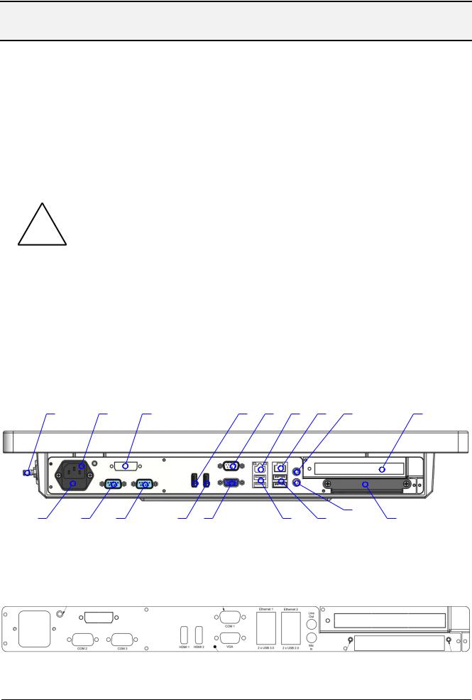
6.1.1.Location
1 |
2 |
3 |
4 |
5 |
6 |
7 |
8 |
9 |
|
|
|
|
|
|
|
|
|
|
|
|
|
|
|
|
17 |
10 |
11 |
12 |
13 |
14 |
15 |
16 |
18 |
Figure 2: Location of interfaces, bottom view without cable cover
Figure 3: Inscription of interfaces on connector/slot panel
Document: Manual_Medical_MLC_1.2 |
Page 12 of 37 pages |
Last change date: 18-Feb-15 |
 Loading...