

ADLINK ND-6510 User Manual

®
NuDAM
ND-6520 RS-232 to RS-422/RS-485 Converter
ND-6510 RS-422/RS-485 Repeater
ND-6530 USB to RS-485/RS-422/RS-232 Converter
ND-6521 Addressable RS-422/RS-485 to RS-232 Converter
User’s Guide
Recycled Paper

© Copyright 1999~2001 ADLINK Technology Inc.
All Rights Reserved.
Manual Rev. 3.00: March 16, 2001
The information in this document is subject to change without prior notice in
order to improve reliability, design and function and does not represent a
commitment on the part of the manufacturer.
In no event will the manufacturer be liable for direct, indirect, special, incidental,
or consequential damages arising out of the use or inability to use the product or
documentation, even if advised of the possibility of such damages.
This document contains proprietary information protected by copyright. All rights
are reserved. No part of this manual may be reproduced by any mechanical,
electronic, or other means in any form without prior written permission of the
manufacturer.
Trademarks
Nudam is registered trademarks of ADLINK Technology Inc.,
Other product names mentioned herein are used for identification purposes only
and may be trademarks and/or registered trademarks of their respective
companies.

Table of Contents
Chapter 1 Introduction ....................................................... 1
1.1 WHAT IS NUDAM ?...............................................................................1
1.2 OUTSTANDING FEATURES OF NUDAM..................................................2
1.3 NUDAM-6000 SERIES PRODUCTS OVERVIEW ........................................3
1.4 EIA RS-485 STANDARD ........................................................................4
1.5 RS-485 ON NUDAM .............................................................................4
1.6 NUDAM RS-485 NETWORK CONFIGURATIONS.....................................5
1.7 CONSTRUCTING A NUDAM NETWORK..................................................8
1.8 TERMINATION BUS ................................................................................8
1.9. SHIELDING .............................................................................................9
1.10. HOW TO CALCULATE CHECKSUM VALUE ............................................10
Chapter 2 NuDAM-6520 ....................................................11
2.1. OVERVIEW...........................................................................................11
2.2 SETUP ..................................................................................................16
2.3. INSTALLATION .....................................................................................18
2.4 PROGRAMMING....................................................................................19
Chapter 3 NuDAM-6510 .................................................... 20
3.1. OVERVIEW...........................................................................................20
3.2. SETUP ..................................................................................................24
3.3 INSTALLATION .....................................................................................26
3.4 PROGRAMMING....................................................................................27
Chapter 4 NuDAM-6530 .................................................... 28
4.1. OVERVIEW...........................................................................................28
4.2 SETUP ..................................................................................................33
4.3 INSTALLATION .....................................................................................35
4.4 PROGRAMMING....................................................................................45
Chapter 5 NuDAM-6521 .................................................... 46
5.1. OVERVIEW...........................................................................................46
5.2 INITIALATION & INSTALLATION...........................................................51
5.3. INSTALL A NEW NUDAM-6521 TO A EXISTING NETWORK .................53
5.4 COMMAND SET ....................................................................................54
Table of Concents • i

5.4.1 Command and Response....................................................................54
5.4.2 Summary of Command Set.................................................................56
5.4.3 Set Configuration...............................................................................57
5.4.4 Read Configuration ...........................................................................60
5.4.5 Read Module Name............................................................................60
5.4.6 Read Firmware Version.....................................................................62
5.4.7 Soft Reset ...........................................................................................63
5.4.8 Reset Status........................................................................................64
5.4.9 Set RTS Status....................................................................................65
5.4.10 Read RTS Status...............................................................................66
5.4.11 Read CTS Status ..............................................................................67
5.4.12 Set Device ID ...................................................................................68
5.4.13 Read Device ID................................................................................69
5.4.14 Set Delimiter ....................................................................................70
5.4.15 Read Delimiter.................................................................................71
5.4.16 Data Pass.........................................................................................72
5.4.17 Open/Close Data Gate.....................................................................73
5.4.18 Read Command Leading Code Setting .......................................74
5.4.19 Change Command Leading Code Setting........................................75
5.4.20 Set Host Watchdog Timer ................................................................77
5.4.21 Read Host Watchdog Timer.............................................................78
5.4.22 Host is OK........................................................................................79
Chapter 6 Software Utility ................................................ 80
6.1 SOFTWARE INSTALLATION...................................................................80
6.2 HOW TO EXECUTE THE NUDAM ADMINISTRATION ............................80
6.3 NUDAM ADMINISTRATION FUNCTION OVERVIEW..............................81
6.3.1 Change RS-232 Communication Port Setting. .................................81
6.3.2 Search all exist Nudam modules........................................................82
6.3.3 Using Operations...............................................................................83
6.3.4 Save and Print Nudam modules’ information....................................87
6.3.5 Version Information...........................................................................88
TROUBLESHOOTING AND MAINTENANCE..........................................89
PRODUCT WARRANTY/SERVICE.................ERROR! BOOKMARK NOT
DEFINED.
ii • Table of Contents

1
Introduction
1.1 What is NuDAM ?
NuDAM is a series of data acquisition modules. It provides a total solution of the
data acquisition network and control system. You can remotely control up to 256
NuDAM modules on RS-485 netowrk. All you need is to use a host computer,
like PC (Personal Computer), with one RS-232 serial port for controlling the
whole system. The maximum communication distance is 4000 feet from the
host computer.
NuDAM is based on the RS-485 multi-drop network system, each module has an
unique address ID. Using simple ASCII command & response protocol through
standard RS-485 interface can control all the NuDAM modules in the RS-485
network.
The NuDAM modules provide direct linkage to a wide variety of sensors and
perform all signal conditioning, scaling, linearization and conversion. The
modules can be used to measure temperature, pressure, flow, voltage, current
and numerous types of digital signals.
Introduction • 1

1.2 Outstanding Features of NuDAM
Industry standard networking
z
All NuDAM modules use the RS-485 communication protocol for transmitting
and receiving at high rates and over long distance.
Two-wire and multi-drop communication
z
A single twisted pair of wires is used to transmit and receive data between
modules. Multi-drop capability makes system configuration more flexible and
easy set-up of a network.
High transfer speed
z
NuDAM modules provide up to 115.2K bps data / command transfer rate. It can
promote system bandwidth.
Simple command / response protocol
z
All communications are performed with printable ASCII characters. This allows
the information to be processed with string functions common to the most
high-level languages.
Industrial design
z
The screw terminal plug connectors on every NuDAM module ensures simple
installation and easy modification. The compact size allows the modules to be
mounted on DIN rail, back-panel wall-mount, etc.
Watch-dog supervisory
z
NuDAM contains a watch-dog supervisory circuitry that will automatically reset
the module when the system fails. In addition, a user-programmable software
timer provides a ‘safe’ output signal in the event of host computer failure.
High isolation voltage
z
NuDAM provides photo-isolators, which ensure high isolation voltage, between
the data acquisition circuits and the communication port. The fatal
electric-shock won‘t go through and damage all the modules on the network.
Noise immunity
z
The NuDAM provide extra noise immunity capability. An electrode, which is
coated inside the ABS case, can reduce electro-magnetic interference (EMI)
and noise.
Harsh environmental protection
z
2 • Introduction

A surface coating covers on the PCB and electronic components of the NuDAM.
It allows superior resistance to harsh environment such as humidity, salt spry
and most harsh chemicals.
1.3 NuDAM-6000 series products overview
The NuDAM-6000 series provides the complete sets of data acquisition modules,
including the communication modules, the analog input modules, the analog
output modules, and the digital I/O modules.
Communication Module
♦ NuDAM-6510 : RS-422/RS-485 Repeater
♦ NuDAM-6520 : RS-232 to RS-422/RS-485 Converter
♦ NuDAM-6530 : USB to RS-422/RS-485 Converter
♦ NuDAM-6521 : Addressable RS-422/RS-485 to RS-232 Converter
Analog Input Modules
♦ NuDAM-6011: Multifunction High Gain Analog Input Module(with
DI/O)
♦ NuDAM-6011D: Multifunction High Gain Analog Input with 5 ½ digit
LED Display(with DI/O)
♦ NuDAM-6012: Analog Input Module(with DI/O)
♦ NuDAM-6012D: Analog Input Module with 5 1/2 digit LED Display(with
DI/O)
♦ NuDAM-6013: 3-channel RTD Input Module
♦ NuDAM-6014D: Analog (Transmitter) Input Module with 5 1/2digit
LED Display
♦ NuDAM-6017: 8-channel Analog Input Module
♦ NuDAM-6018: 8-channel Thermocouple Input Module
Analog Output Modules
♦ NuDAM-6021: Single Channel Analog Output Module
♦ NuDAM-6024: 4-channel Analog Output Module(with DI)
Digital I/O Modules
♦ NuDAM-6050 : Module with 7 DI channels and 8 DO channels
♦ NuDAM-6052 : Isolated Digital Input Module
♦ NuDAM-6053 : 16-channel digital Input Module
♦ NuDAM-6054 : 15-channel digital Input Module
♦ NuDAM-6056 : 15-channel digital Output Module
♦ NuDAM-6058 : 28-channel programable digital I/O Module
♦ NuDAM-6060 : 4-channel Relay Output & Digital Input Module
Introduction • 3

♦ NuDAM-6063 : 8-channel Relay Output Module
♦ NuDAM-6080 : Counter/Frequency Input Module
1.4 EIA RS-485 Standard
The EIA RS-485 interface is a communication standard developed for
multi-dropped systems that can communicate at high rate over long distance.
The standard RS-485 can operate at speed up to 10 M bps over cable length up
to 4000 feet.
The RS-485 interface can support up to 32 drivers / receivers on the same line.
This allows actual networking applications on a parity line system (sometimes
called multi-drop).
The RS-485 uses differential transmission on a balance line. Its easy wiring
make it popular to use in industrial applications.
1.5 RS-485 on NuDAM
The NuDAM improves the RS-485 capability for minimizing the user‘s cost. On
each NuDAM module, a half-duplex RS-485 transceiver is used to communicate
with other modules. A single twisted pair of wires, which provides standard
differential transmission, is used to transmit and receive data between modules.
The high input impedance of each NuDAM receiver allows up to 128 NuDAM
modules on the same RS-485 bus without using a signal repeater.
The maximum transfer rate of NuDAM is 115.2Kbps which is lower than the
maximum speed of the RS-485 standard. The slew-rate limiter on every RS-485
transceiver of NuDAM is very useful for transmitting error-free data, minimizing
EMI, and reducing reflections caused by improperly terminated cables.
The NuDAM on a network may not use the same power supply. Therefore, the
voltage difference between ground of the modules may exist.
Excessive output current and power dissipation caused by faults or by bus
contention are prevented by the current limiter and the thermal shutdown
circuitry inside the NuDAM.
4 • Introduction
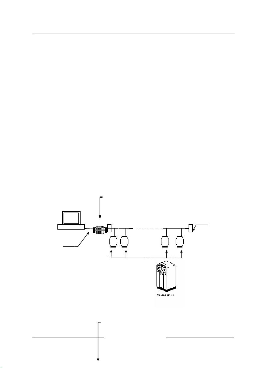
1.6 NuDAM RS-485 Network Configurations
T
r
NuDAM-6000 series is designed under RS-485 multi-drop network architecture.
Up to 256 NuDAM modules can be controlled in a multi-drop network. The limit
of 256 is due to command code. The network can be connected by simple
topology (Figure 1-1) or branch topology (Figure 1-2) or free topology (Figure
1-3).
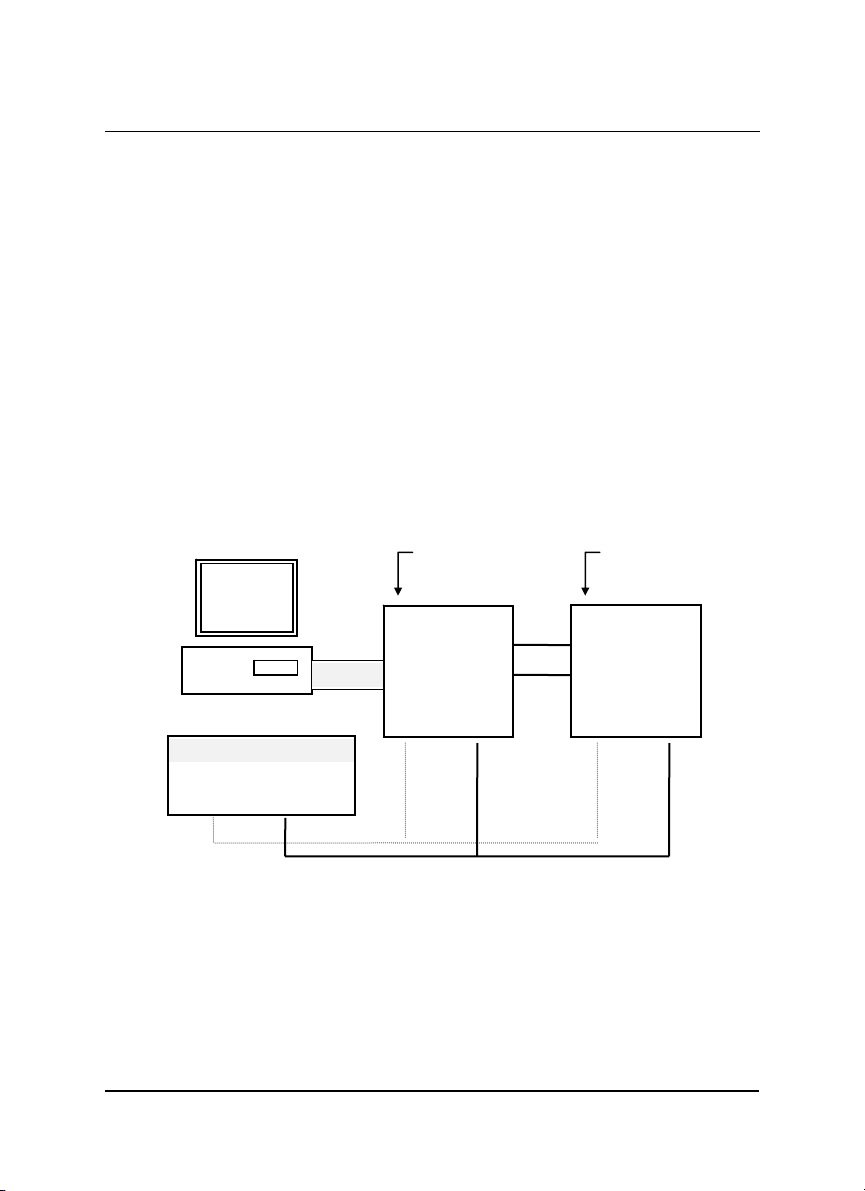
The ND-6520 and ND-6510 are the two basic communication modules to
construct a RS-485 network. The ND-6520 is a RS-232 to RS-485/RS-422
converter. The ND-6520 is used to build a RS-485 port for the host computer by
converting standard RS-232 signal into RS-485 signal.
The ND-6510 is the RS-485 signal repeater which is used to extend or to
lengthen the network distance. A NuDAM bus can connect up to 256 modules,
each segment is up to 128 modules. Whenever the numbers of the modules
excess 128, the repeater should be used. In addition, the length of a standard
RS-485 bus is up to 4000 feet, the repeater should be used whenever the length
of a signal bus is more than 4000 feet.
The ND-6530 is the USB to RS-485/RS-422/RS-232 converter, and it used to
build the USB signal into RS-485/RS-422/RS-232 signal.
The ND-6521 is an addressable RS-485/RS-422 to RS-232 converter, it allows
the RS-232 devices easily link to Host by the RS-485/422 bus.
Host
RS-232
NuDAM Modules
ND-6520: RS-232 to
ND-6520
RS-485/RS-422
RS-232/RS-485
ND-6530: USB to
Converter
RS-232/RS485/RS-422
Converter.
RS-485 bus
Converter
erminato
ND-6521
Figure 1-1 Simple Topology
ND-6520: RS-232 to
RS-485/RS-422
ND-6530: USB to
RS-232/RS485/RS-422
Converter.
Converter
Introduction • 5
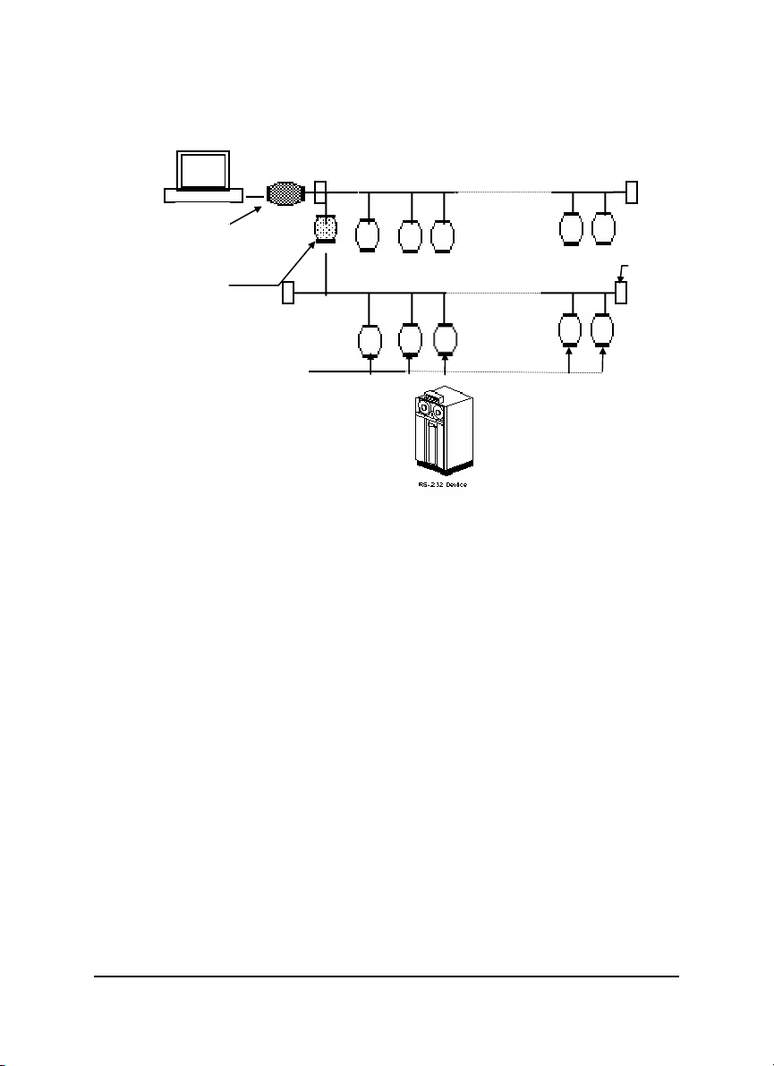
T
r
Host
RS-232
ND-6510
Repeater
RS-485 bus
RS-485 bus
erminato
NuDAM Modules
ND-6521
6 • Introduction
Figure 1-2 Branch Topology
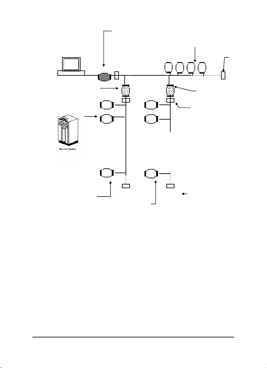
ND-6520: RS-232 to
T
r
T
r
T
r
Host
ND-6510
Repeater
RS-485/RS-422
ND-6530: USB to
RS-232/RS485/RS-422
Converter.
RS-485 bus
ND-6521
Converter
NuDAM Modules
ND-6510
Repeater
erminato
erminato
NuDAM I/O
modules
NuDAM I/O modules
Figure 1-3 Free Topology
erminato
Introduction • 7
1.7 Constructing a NuDAM Network
Go through the following steps, the user can construct a NuDAM network easily.
1. Setup a ND-6520 or ND-6530.
2. Connect the host computer with the ND-6520 or ND-6530.
3. Setup one or more ND-6510 if necessary.
4. Connect the ND-6510 to extend to RS-485 bus if necessary.
5. Install the NuDAM utility software or ND-6530 driver from disk.
6. Initialize the brand-new NuDAM modules.
7. Add the new NuDAM modules into RS-485 network.
Refer to chapter 2 and chapter 4 for executing step 1 and 2. Refer to chapter 3
for executing step 3, 4 and for understanding the time to install ND-6510. The
knowledge about the software for operating the NuDAM is in chapter 6. For
executing the step 6 and step 7, please refer to the install procedures of each
module and chapter 6.
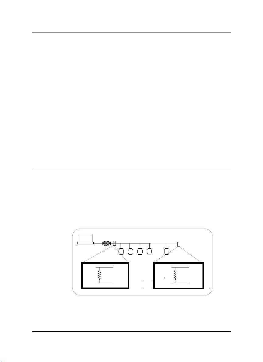
1.8 Termination Bus
In order to avoid signal reflections on the bus, each bus segment has to be
blanked off at its physical beginning and at its end with the characteristic
impedance. An termination resister ( Rt) is intalled for this purpose. The Rt value
- 120Ω ± 2% is recommended, and the detailed connection of Rt can be referred
from the “Terminator Connection” diagram below.
8 • Introduction
Host
Data+
Data-
120 ohms
Data+
Data-
Terminator Connection
120 ohms
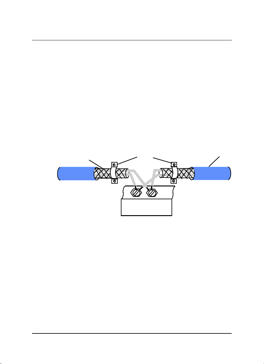
1.9. Shielding
In case of increased interference, a shielded bus cables is recommended to use
for wiring between module and modules. In addition, a shielding also should be
done for the cable of power supply and for the signal cables.
Some experiences and recommendations are concerning for shield connection.
1. The shield should be connected with protective earthing at each bus
connection.
2. The shield should be applied additionally several times along the course of the
cable.
3. The Computer should be applied the shield directly to the appliance or to
separate shield rails.
braided shield
RS-485 Connection Cable
Earthing Point
DATA+
DATA -
Isolation
NuDAM Module
Introduction • 9

1.10. How to Calculate Checksum Value
Format of NuDAM Commands
(LeadingCode)(Addr)(Command)(Data)
When checksum is enable then [Checksum] is needed, it is 2-character.
[Checksum] =
Example 1: checksum is
Example 2: checksum is
B7 = (
0x24 + 0x30 + 0x31 + 0x32
AC= (
0x24+ 0x30+ 0x31+ 0x34+ 0x30+ 0x30+ 0x36+ 0x30+ 0x30)
(LeadingCode)+(Addr)+(Command)+(Data)
(
disable
User Command : $012<CR>
Response : !01400600
enable
User Command :
Response :
‘$’ = 0x24 ‘0’ = 0x30 ‘1’ = 0x31 ‘2’ = 0x30
‘!’ = 0x24 ‘0’ = 0x30 ‘1’ = 0x31 ‘4’ = 0x34
‘6’ = 0x36
[Checksum]
$012B7<CR>
!01400600AC
) MOD 0x100
<CR>
) MOD 0x100
MOD 0x100
10 • Introduction

2
NuDAM-6520
2.1. Overview
What is NuDAM-6520 ?
NuDAM-6520 is a RS-232 to RS-422/RS-485 converter, it converts the RS-232
signal to the RS-422/RS-485 signals. The ND-6520 can be considered as an
extension RS-422/RS-485 serial port for the host computer. A standard 9-pin
D-type connector is used to connect the host computer and the ND-6520.
Hence, the ND-6520 can connect with all kinds the PC, IPC or Notebook PC,
which install a standard RS-232 interface.
Features of NuDAM-6520
♦ RS-422/RS-485 transceiver
♦ Differenial 2-wire half-duplex RS-485
♦ Easily setup and installation
♦ Auto direction flow control
♦ Maximum 128 NuDAM on a bus without using repeaters
♦ Maximum 256 addressable NuDAM modules
♦ High transfer speed
♦ High isolation voltage
♦ Lower power consumption
NuDAM-6520 • 11

Specifications of NuDAM-6520
Input
♦ Interface : standard RS-232 9 pin female D-type connector
♦ Speed (bps) : 1200(115.2K
1
), 2400, 4800, 9600, 19.2K, 38.4K, RTS
♦ Data Format : 9 bits, 10 bits, 11 bits, or 12 bits
Output
♦ Interface :RS-485, differential, 2 half-duplex wires RS-422, differential,
4 full-duplex wires
♦ Speed (bps) : 1200(115.2K
1
), 2400, 4800, 9600, 19.2K, 38.4K, RTS
♦ Max RS-485 network bus distance : 4000 ft. (1200m)
Isolation
♦ Isolation voltage : 5000 Vrms(between RS-422/RS-485 network and
host computer)
Bus
♦ Max loading : 128 NuDAMs on a RS-485 network
♦ Max modules : 256 NuDAMs with one ND-6510 repeater
Power
♦ Power Supply : +10V to +30V
♦ Power Consumption : 0.95 W
Note 1: 115.2K is supported by Firmware version A1.2 or later.
12 • NuDAM-6520
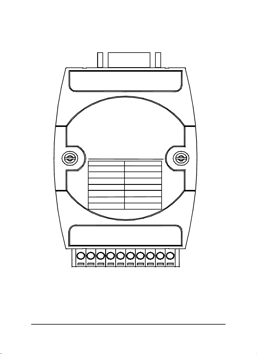
A Look at NuDAM-6520 & Pin Assignment
(
)
N
(Y) DATA+
)
bp
bp
RS-232 IN
RS-232 to RS-485
D-6520
Switch Position
SW1: ON
SW2: ON
SW3: ON
SW4: ON
SW5: ON
SW6: ON
SW7: ON
/RS-422Converter
Baud Rate
RTS CTRL
115.2K bps
2400
s
4800 bps
9600 bps
19.2K bps
38.4K
s
DATAG
TX-
TX+
RX+
TX-
(B)GND
(R)+Vs
NuDAM-6520 • 13
Pin Definitions
r
Pin # Signal Name Description
1 (Y)DATA+ RS-485 transmission line, positive
2 (G)DATA- RS-485 transmission line, negative
4 TX+ RS-422 transmission line, positive
5 TX- RS-422 transmission line, negative
6 RX+ RS-422 receiving line, positive
7 RX- RS-422 receiving line, negative
9 (R)+VS NuDAM power supply, +10V~+30V
10 (B)GND NuDAM ground
-- RS-232 IN 9-pin RS-232 connector
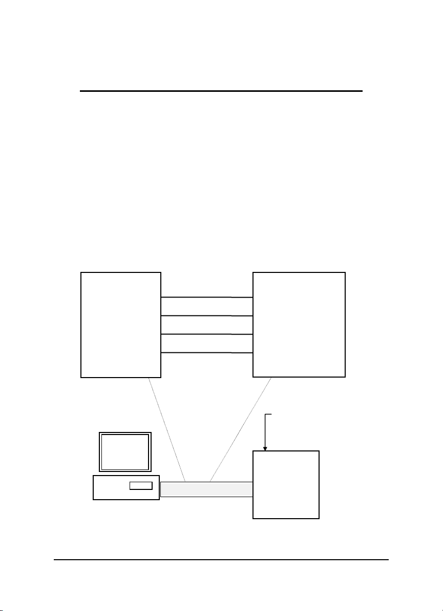
Connection Between Host and ND-6520
Host RS-232
RTS t
GND r
TXD p
RXD o
Host
Computer
RS-232
ND-6520 RS-232
i RTS
g GND
e TXD
d RXD
NuDAM-6520
RS-232/RS-485
Converte
DATA +
DATA -
+Vs GND
14 • NuDAM-6520
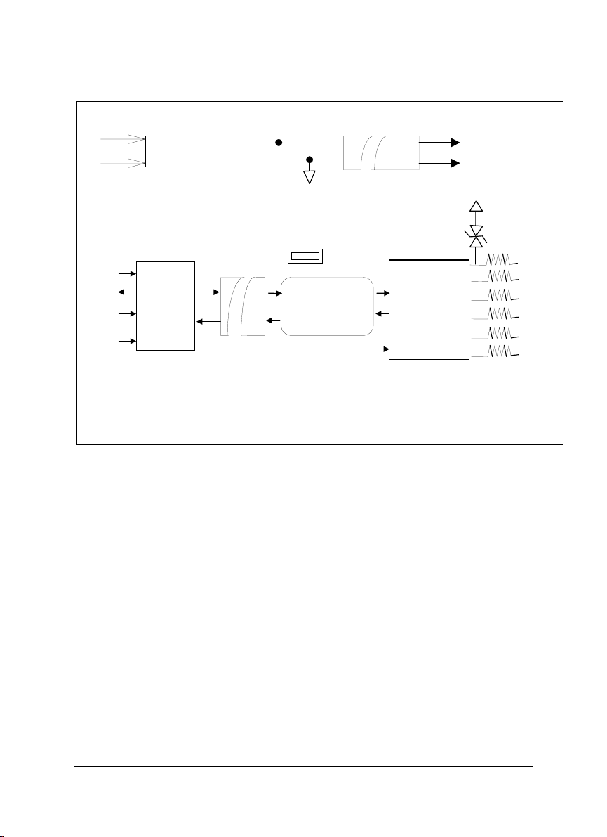
Functional Block Diagram
r
r
r
p
VS
Power Regulato
& Filte
Power Input
+10V ~ +30V
+5V
GND
Isolation +5V
Isolation GND
DC to DC
Converte
TXD
RXD
RTS
RS-232
Receiver
/ Driver
GND
Opto-Isolation
TVS : Transient Voltage Suppresser
PTC : Positive Tem
SW1
Communication
Switching
Controller
Communication
Direction Control
erature Coefficient
T
RS-422/RS-485
Receiver/Driver
PTC
Data+
Data-
Rx+
Rx-
Tx+
Tx-
NuDAM-6520 • 15

2.2 Setup
Objective of Setup
In normal condition, it is not necessary to setup the NuDAM-6520. The default
configuration of this communication module is 9600 bps and data format of 8
data bits with 1 start bit, 1 stop bit, and no parity check. Note that the data format
is reserved to be compatible with other brand‘s communication port, it should not
be modified if only NuDAM is used in a system. The baud rate can be
configured according applications’ requirement.
Setup Equipments
Only screw driver is used to open the case. Software, power supply, and wiring
are not necessary.
Setup Procedure
Only hardware switch setting can be setup in ND-6520. The user can set the
speed of the serial interface ( RS-232 and RS-422/RS-485 ), and the serial data
format. The speed and the data format on the whole RS-485 network must be
identity otherwise the communication will be not correct.
To setup the ND-6520, use the screw driver to open the case, then change the
switch setting. The new setting is available after power on. The case must be
put back and locked carefully. Note that do not scratch the surface of the circuit
while setting up, otherwise the surface coating or even the circuits will be
damaged.
(Note: For Harware Rev.C1 or upper, there is switchless for
Baudrate adjust. It is auto baudrate and parity, data bits
adjust.)
Default Setting
♦ 9600 baud rate
♦ 10 bits series data format : one start bit, eight data bits, one stop bit,
no parity check
16 • NuDAM-6520
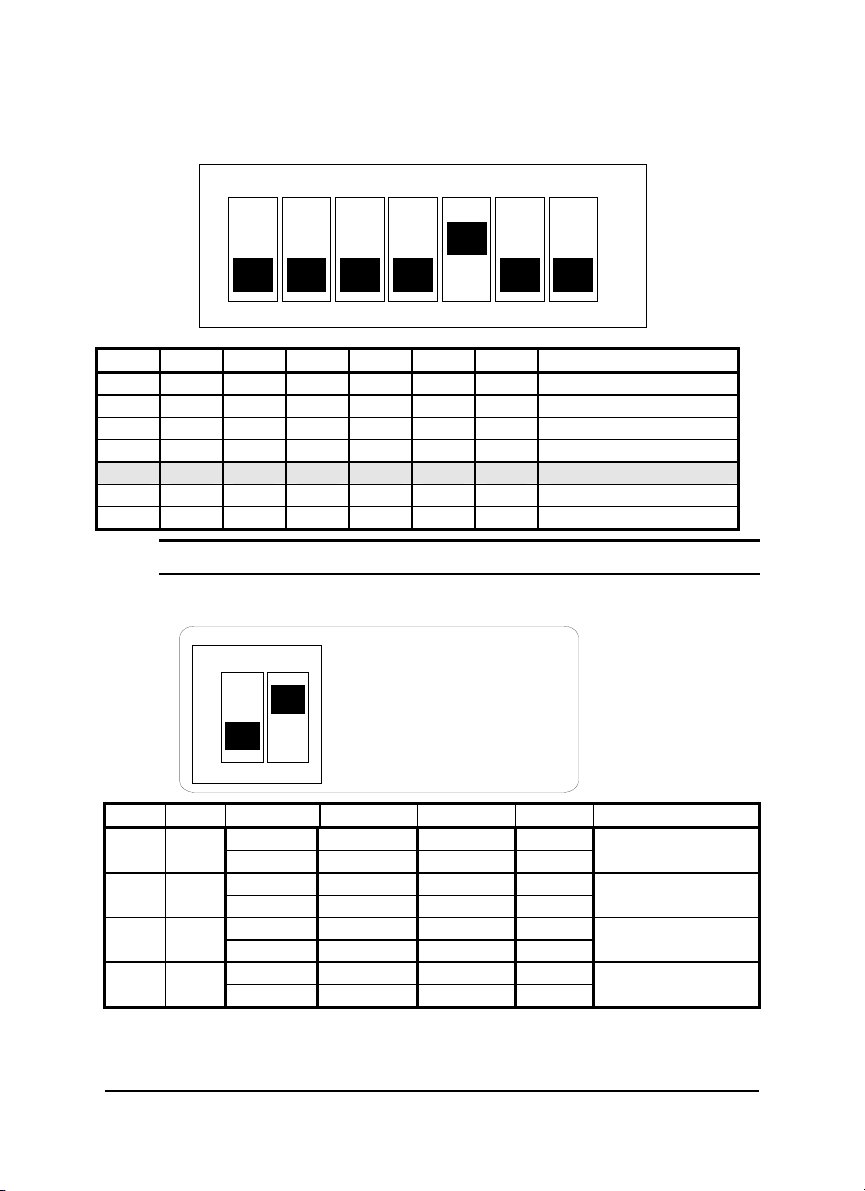
SW1 Setting
g (
)
p
SW 1 D efault S e ttin
ON
1 2 3 4 5 6 7
OFF
9600 bps
1 2 3 4 5 6 7 Baud Rate
ON OFF OFF OFF OFF OFF OFF RTS Control
OFF ON OFF OFF OFF OFF OFF 1200 or 115.2k1 bps
OFF OFF ON OFF OFF OFF OFF 2400 bps
OFF OFF OFF ON OFF OFF OFF 4800 bps
OFF OFF OFF OFF ON OFF OFF 9600 bps
OFF OFF OFF OFF OFF ON OFF 19200 bps
OFF OFF OFF OFF OFF OFF ON 38400 bps
Note 1: 115.2kbps is supported by version A1.2 or later.
SW2 Setting
ON
12
S W 2 D e fa u lt Settin g
S tart B its : 1
Data Bits : 8
Sto
Bits : 1
P arity : N o n e
1 2 Start Bit Data Bits Stop Bit Parity Packet Data Bits
1 7 1 0 OFF OFF
9
1 6 1 1
1 8 1 0 OFF ON
10
1 7 1 1
1 9 1 0 ON OFF
11
1 8 1 1
1 10 1 0 ON ON
12
1 9 1 1
NuDAM-6520 • 17
2.3. Installation
r
Software Utility
Software is not necessary for this module.
Equipments for Installation
A host computer with RS-232 port
RS-232 cable (DB-9 female)
DC Power supply (+10V~+30V) (NDP-243u is recommended)
Wires (shielded and grounded is recommended)
Installation Procedure
1. Make sure the host computer is power off.
2. Use RS-232 cable to connect NuDAM-6520 with host computer.
3. Wire the power supply to NuDAM. Note that the power supply should meet
the specification.
4. Wire other NuDAMs.
Application Wiring
The Figure 2-1 shows the application wiring of NuDAM-6520.
Host
Computer
RS-232
Local Power Supply
+10 V to +30 V
+Vs GND
Figure 2-1 Application wiring of NuDAM-6520
NuDAM-6520
RS-232/RS-485
Converte
DATA +
DATA -
+Vs GND
NuDAM
module
+ DATA
- DATA
+Vs GND
18 • NuDAM-6520

2.4 Programming
The NuDAM-6520 is a communication module, it is not necessary to be
programmed
NuDAM-6520 • 19

3
NuDAM-6510
3.1. Overview
What is NuDAM-6510 ?
The ND-6510 is the RS-422/RS-485 signal repeater which is used to extend or
to lengthen the network distance. A NuDAM bus can connect up to 128 modules.
The repeater should be used when the numbers of the modules excess 128. In
addition, the repeater should also be used when the length of a signal bus is
more than 4000 feet.
Features of NuDAM-6510
z RS-422/RS-485 signal transceiver & repeater
z Bi-directions signal transmission for both RS-422/RS-485 ports
z Automatic transmission direction control
z Easily setup and installation
z Maximum 128 NuDAM on a bus
z Maximum 256 addressable NuDAM modules
z High transfer speed
z Surge protection
z Lower power consumption
Specifications of NuDAM-6510
20 • NuDAM-6510

Input / Output
♦ Interface : RS-485, differential 2 half-duplex wires RS-422, differential, 4
full-duplex wires
♦ Speed (bps) : 1200(115.2K
1)
, 2400, 4800, 9600, 19.2K, 38.4K
♦ Data Format : 9 bits, 10 bits, 11 bits, or 12 bits
♦ Max RS-485 network bus distance : 4000 ft. (1200m)
Note 1: 115.2k is supported by version A1.2 or later.
Bus
♦ Max Loading : 128 NuDAMs on a bus
Power
♦ DC Power Supply : +10V to +30V
♦ Power Consumption : 0.9 W
NuDAM-6510 • 21
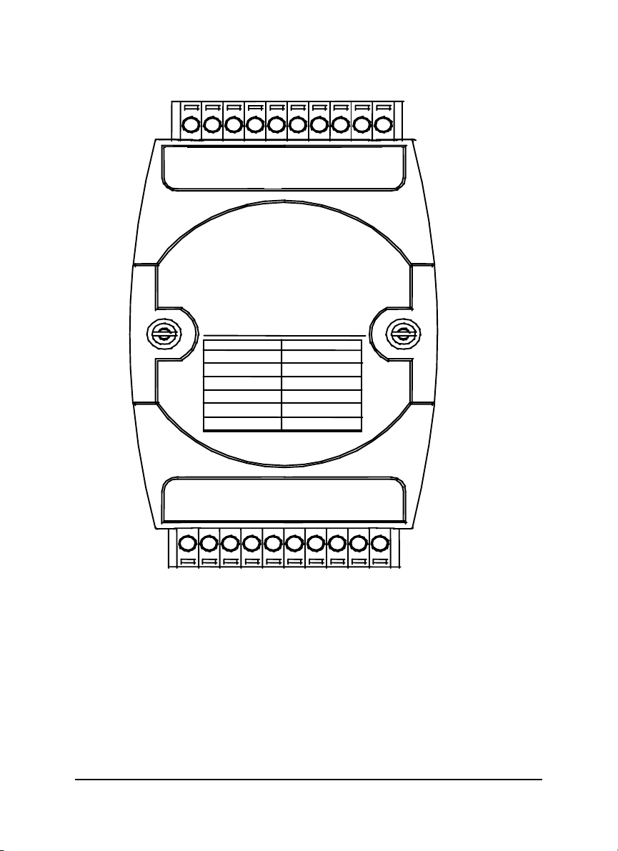
A Look at NuDAM-6510 & Pin Assignment
N
)
bp
r
20
DATA+ (Y)
DATA- (G)
D-6510
Switch Position Baud Rate
SW1-1: ON 115.2K bps
SW1-2: ON
SW1-3: ON
SW1-4: ON
SW1-5: ON
SW1-6: ON
DATAG
(Y)DATA+
Tx+
Rx-
Rx+
RS-422/RS-485
Repeapte
2400
s
4800 bps
9600 bps
19.2 K bps
38.4 K bps
RX-
Rx+
Tx-
11
(R)+Vs
(B)GND
22 • NuDAM-6510
Pin Definitions
r
r
V
V
D
r
+
n
g
r
+
Pin # Signal Name Description
1 (Y)DATA+ RS-485 transmission line, positive
2 (G)DATA- RS-485 transmission line, negative
4 TXIN+ RS-422 transmission input line, positive
5 TXIN- RS-422 transmission input line, negative
6 RXOUT+ RS-422 receiving output line, positive
7 RXOUT- RS-422 receiving output line, negative
9 (R)+VS NuDAM power supply, +10V~+30V
10 (B)GND NuDAM ground
14 RXIN- RS-422 receiving input line, negative
15 RXIN+ RS-422 receiving input line, positive
16 TXOUT- RS-422 transmission output line, negative
17 TXOUT+ RS-422 transmission output line, positive
19 (G)DATA- RS-485 transmission line, negative
20 (Y)DATA+ RS-485 transmission line, positive
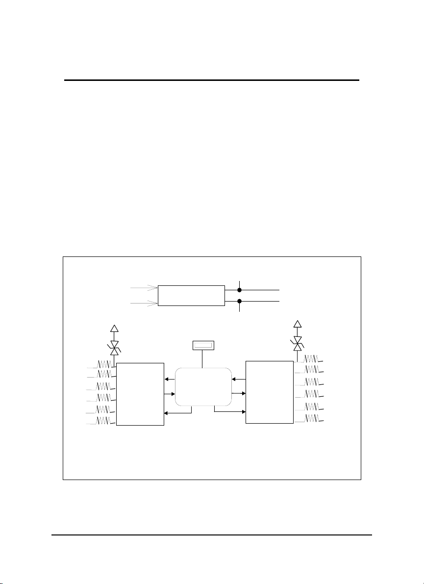
ND-6510 Functional Block Diagram
+5
Power Input
+10V ~ +30
Power Regulato
& Filte
GN
Data
Data-
Rx+
Rx-
Tx+
Tx-
RS-422/RS-485
Receiver/Dr iver
SW1
Communicatio
Switchin
Controlle
Communication
T
RS-422/RS-485
Receiver/Dr iver
PTC
Data
Data-
Rx+
Rx-
Tx+
Tx-
Direction
Control
TVS : Transient Voltage Suppresse
PTC : Positive Temperature Coefficient
NuDAM-6510 • 23

3.2. Setup
Objective of Setup
In normal condition, it only needs to setup the NuDAM-6510 when the NuDAM
bus with more than 128 modules or the distance exceeds 4000 feet long. The
default configuration of this communication module is 9600 bps and data format
of 8 data bits with 1 start bit, 1 stop bit, and no parity check. Note that the data
format is reserved to be compatible with other brand‘s communication port, it
should not be modified if only NuDAM is used in a system. The baud rate can
be configured according user’s requirement.
Setup Equipments
Only screw driver is used to open the case. Software, power supply, and wiring
are not necessary.
Setup Procedure
Only hardware switch setting can be setup in ND-6510. The user can set the
speed and the data format of the RS-422/RS-485 interface. The speed and the
data format on the whole network must be identity otherwise the communication
may be not correct.
To setup the ND-6510, use the screw driver to open the case, then change the
switch setting. The new setting is available after power on. The case must be
put back and locked carefully. Note that do not scratch the surface of the circuit
while setting up, otherwise the surface coating or even the circuits will be
damaged.
(Note: For Harware Rev.C1 or upper, there is switchless for
Baudrate adjust. It is auto baudrate and parity, data bits
adjust.)
Default Setting
♦ 9600 Baud rate
♦ 10 bits serial data format : one start bit, eight data bits, one stop bit, no
parity check
24 • NuDAM-6510
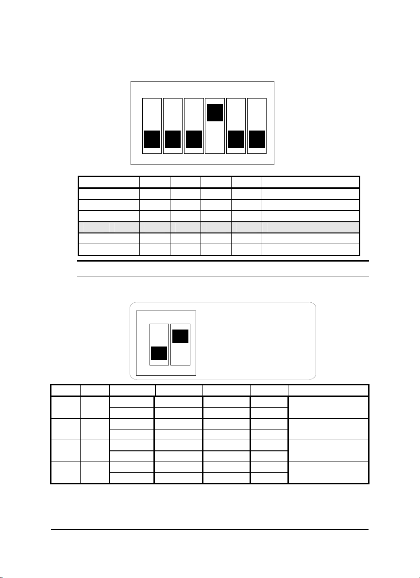
SW1 Setting
)
p
SW1 Default Setting (9600 bps
ON
OFF
1 2 3 4 5 6 Baud Rate
ON
OFF
OFF OFF OFF OFF OFF 1200 or 115.2k
ON
OFF OFF
OFF OFF OFF
OFF OFF OFF OFF
OFF OFF OFF OFF OFF
2 3 4 5 6
1
OFF OFF OFF OFF 2400 bps
ON
OFF OFF OFF 4800 bps
ON
OFF OFF 9600 bps
ON
OFF 19200 bps
ON
38400 bps
1
bps
Note 1: 115.2kbps is supported by version A1.2 or later.
SW2 Setting
ON
12
S W 2 D e fa ult S e ttin g
S tart B its : 1
D ata B its : 8
B its : 1
Sto
P ar ity : N o n e
1 2 Start Bit Data Bits Stop Bit Parity Packet Data Bits
1 7 1 0 OFF OFF
1 6 1 1
1 8 1 0 OFF ON
1 7 1 1
1 9 1 0 ON OFF
1 8 1 1
1 10 1 0 ON ON
1 9 1 1
9
10
11
12
NuDAM-6510 • 25
 Loading...