

Page 1
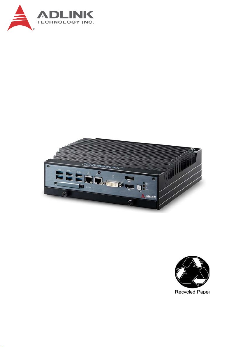
MXE-5400 Series
MXE-5401
Fanless Embedded Computer
User’s Manual
Manual Rev.: PRELIMINARY
Revision Date: Dec. 20, 2013
Part No: 50-PRE
Advance Technologies; Automate the World.
Page 2
PRELIMINARY
Revision History
Revision Release Date Description of Change(s)
PRELIMINARY Dec.20, 2013 Pre-Initial Release
Please note that this is a PRELIMINARY version of the
User’s Manual. While every effort has been made to
NOTE:
NOTE:
ensure the contents hereof are currently accurate, subsequent releases may contain changes to the specification and operations, both minor and major, as well as
entirely new chapters and modules not represented
here.
For more information or if you have any questions,
please visit our website at http//.www.adlinktech.com or
contact your local Sales Center, as detailed in Getting
Service.
ii
Page 3

PRELIMINARY
MXE-5400
Preface
Copyright 2014 ADLINK Technology, Inc.
This document contains proprietary information protected by copyright. All rights are reserved. No part of this manual may be reproduced by any mechanical, electronic, or other means in any form
without prior written permission of the manufacturer.
Disclaimer
The information in this document is subject to change without prior
notice in order to improve reliability, design, and function and does
not represent a commitment on the part of the manufacturer.
In no event will the manufacturer be liable for direct, indirect, special, incidental, or consequential damages arising out of the use or
inability to use the product or documentation, even if advised of
the possibility of such damages.
Environmental Responsibility
ADLINK is committed to fulfill its social responsibility to global
environmental preservation through compliance with the European Union's Restriction of Hazardous Substances (RoHS) directive and Waste Electrical and Electronic Equipment (WEEE)
directive. Environmental protection is a top priority for ADLINK.
We have enforced measures to ensure that our products, manufacturing processes, components, and raw materials have as little
impact on the environment as possible. When products are at their
end of life, our customers are encouraged to dispose of them in
accordance with the product disposal and/or recovery programs
prescribed by their nation or company.
Trademarks
Product names mentioned herein are used for identification purposes only and may be trademarks and/or registered trademarks
of their respective companies.
Preface iii
Page 4
PRELIMINARY
Conventions
Take note of the following conventions used throughout this
manual to make sure that users perform certain tasks and
instructions properly.
Additional information, aids, and tips that help users perform
tasks.
NOTE:
NOTE:
Information to prevent minor physical injury, component dam-
age, data loss, and/or program corruption when trying to com-
CAUTION:
WARNING:
plete a task.
Information to prevent serious physical injury, component
damage, data loss, and/or program corruption when trying to
complete a specific task.
iv Preface
Page 5

PRELIMINARY
MXE-5400
Table of Contents
Revision History...................................................................... ii
Preface.................................................................................... iii
List of Tables.......................................................................... ix
List of Figures........................................................................ xi
1 Introduction ........................................................................ 1
1.1 Overview.............................................................................. 1
1.2 Features............................................................................... 2
1.3 Specifications....................................................................... 3
1.4 Unpacking Checklist ............................................................ 5
1.5 Mechanical Drawings........................................................... 6
1.6 Front Panel I/O Connectors ................................................. 8
1.6.1 Power Button .............................................................. 8
1.6.2 LED Indicators ............................................................ 9
1.6.3 Reset Button............................................................... 9
1.6.4 Dual DisplayPort Connector ..................................... 10
Multi-Display Option ...................................................... 11
1.6.5 DVI-I Connector........................................................ 11
1.6.6 Dual Gigabit Ethernet Ports...................................... 13
1.6.7 USB 3.0 Ports........................................................... 14
1.6.8 CFast Port ................................................................ 15
1.7 Rear Panel I/O Connectors................................................ 15
1.7.1 DB-62P COM Port and Digital I/O Connector........... 16
Isolated Digital Input Circuits ........................................ 19
Isolated Digital Output Circuits ..................................... 21
1.8 Internal I/O Connectors...................................................... 22
1.8.1 Clear CMOS Jumper ................................................ 23
1.8.2 DC 5V and 3.3V Connectors for GPS Module.......... 23
v
Page 6

PRELIMINARY
1.8.3 USIM Port ................................................................. 24
1.8.4 SATA Connectors (X2) ............................................. 24
1.8.5 Mini-PCIe Connectors............................................... 25
1.8.6 Extendable Power/Reset/LED .................................. 26
2 Getting Started.................................................................. 27
2.1 Installing Hard Disk Drives................................................. 27
2.2 Installing a Mini-PCIe Device............................................. 31
2.3 Internal USB Connector..................................................... 33
2.4 Installing CFast Card ......................................................... 34
2.5 COM Ports and DIO Device............................................... 36
2.6 Connecting DC power........................................................ 38
2.7 Wall-mounting the MXE-5400............................................ 38
2.8 Cooling Considerations...................................................... 41
3 Driver Installation.............................................................. 43
3.1 Installing the Chipset Driver............................................... 43
3.2 Installing the Graphics Driver............................................. 44
3.3 Installing the Ethernet Driver.............................................. 44
3.4 Installing the Audio Driver.................................................. 45
3.5 Installing the SEMA utility, WDT and DI/O Drivers ............ 45
A Appendix: Watchdog Timer (WDT) &
DI/O Function Libraries.....................................................47
A.1 WDT with API/Windows ..................................................... 47
InitWDT ......................................................................... 47
SetWDT ........................................................................ 48
A.2 DI/O with API/Windows...................................................... 50
GPIO_Init ...................................................................... 50
GPI_Read() ................................................................... 50
GPO_Write() ................................................................. 51
GPO_Read() ................................................................. 51
vi
Page 7

PRELIMINARY
MXE-5400
B Appendix: BIOS Setup......................................................53
B.1 Main ................................................................................... 54
B.1.1 BIOS Information ...................................................... 54
B.1.2 System Time/System Date ....................................... 54
B.2 Advanced........................................................................... 55
CPU Configuration ........................................................ 56
Memory Configuration .................................................. 58
Onboard Device Configuration ..................................... 59
Advanced Power Management ..................................... 61
SATA Configuration ...................................................... 62
Serial Port Console Redirection .................................... 63
AMT Configuration ........................................................ 64
Intel® Rapid Start Technology ...................................... 65
Trusted Computing Configuration ................................. 66
System Management (SEMA) ...................................... 67
B.3 Chipset............................................................................... 68
B.4 Boot ................................................................................... 69
Boot Configuration ........................................................ 69
Boot Option Priorities .................................................... 70
B.5 Security .............................................................................. 70
B.6 Exit ..................................................................................... 71
Important Safety Instructions.............................................. 73
Getting Service...................................................................... 75
vii
Page 8

PRELIMINARY
This page intentionally left blank.
viii
Page 9

PRELIMINARY
MXE-5400
List of Tables
Table 1-1: MXE-5400 Front Panel I/O Connector Legend........... 8
Table 1-2: LED Indicators ............................................................ 9
Table 1-3: DisplayPort Pin Assignment ..................................... 10
Table 1-4: Multi-Display Configuration....................................... 11
Table 1-5: DVI-I Connector Pin Assignment .............................. 12
Table 1-6: Gigabit Ethernet Port LED Function ......................... 14
Table 1-7: MXE-5400 Rear Panel I/O Connector Legend ......... 15
Table 1-8: DB-62P COM Port Pin Assignment .......................... 17
Table 1-9: D-SUB 9P COM Pin Assignment.............................. 18
Table 1-10: Digital I/O Specifications........................................... 18
Table 1-11: D-SUB 26P Pin Assignment on Digital I/O Port........ 19
Table 1-12: MXE-5400 Internal I/O Legend................................. 22
Table 1-13: Clear CMOS Jumper Pin Assignment ...................... 23
Table 1-14: DC 5V and 3.3V Connectors Pin Assignments ........ 24
Table 1-15: Extendable Power/Reset/LED Connectors
Pin Assignments....................................................... 26
Table B-1: Restore On Power Loss Settings ............................. 61
List of Tables ix
Page 10

PRELIMINARY
This page intentionally left blank.
xList of Tables
Page 11

PRELIMINARY
MXE-5400
List of Figures
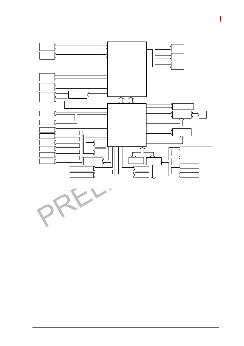
Figure 1-1: MXE-5400 Functional Block Diagram......................... 5
Figure 1-2: Top View..................................................................... 6
Figure 1-3: Front View .................................................................. 7
Figure 1-4: Rear View ................................................................... 7
Figure 1-5: (Left) Side View .......................................................... 7
Figure 1-6: Front Panel I/O ........................................................... 8
Figure 1-7: Gigabit Ethernet Ports .............................................. 14
Figure 1-8: Rear Panel I/O .......................................................... 15
Figure 1-9: DB-62P COM Port .................................................... 16
Figure 1-10: D-SUB 9P COM Connector...................................... 17
Figure 1-11: D-SUB 26P Connector on Digital I/O Port................ 19
Figure 1-12: Isolated Digital Input Circuit...................................... 19
Figure 1-13: Isolated/Differential Digital Input Circuit.................... 20
Figure 1-14: Isolated Digital Input Sample Application Circuit...... 20
Figure 1-15: Isolated Digital Output Circuits ................................. 21
Figure 1-16: Isolated Digital Output Sample Application Circuit ... 21
Figure 1-17: Internal I/O ................................................................ 22
Figure 1-18: Clear CMOS Jumper Pin Settings ............................ 23
Figure 1-19: DC 5V and 3.3V Connectors Configuration .............. 24
Figure 1-20: Mini-PCIe Connector Jumper Settings ..................... 25
Figure 1-21: Extendable Power/Reset/LED Configuration............ 26
List of Figures xi
Page 12

PRELIMINARY
This page intentionally left blank.
xii List of Figures
Page 13
PRELIMINARY
1 Introduction
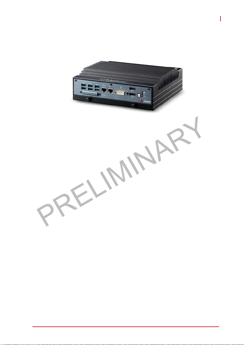
1.1 Overview
MXE-5400
ADLINK’s new Matrix MXE-5400 series of rugged quad-core fanless computers, featuring the latest 4th generation Intel
i7-4700EQ processors (codename: Haswell), delivers outstanding
performance with minimal power consumption. Intel’s Quick Sync
Technology and Core IPG equip the MXE-5400 with market leading performance in image/video related applications.
®
With the implementation of Intel
1.2, Intel VT) technology and ADLINK’s proprietary SEMA (Smart
Embedded Management Agent) tool, the MXE-5400 maximizes
manageability and security for a world of applications. Together
they provide efficient remote monitoring of system activity and
health in real time, system control over a robust secured channel,
and complete fully manageable utilization of system resources.
The MXE-5400 series accommodates rich I/O interfaces in a compact system size, offering versatile connection to a wide range of
applications. Dual mini PCIe slots and USIM socket empower the
MXE-5400 to act as a communications hub for a variety of wireless connections, such as BT/WiFi and 3G. One slot is also configurable to a mini SATA interface, cooperating with internal SATA
storage to deliver RAID 0/1 functionality.
Leveraging proprietary mechanical engineering, the MXE-5400
series continues to offer all the popular features of the Matrix E
series, including cable-free construction, wide operating tempera-
vPro™ (iAMT™ 9.0, TXT, TPM
®
Core
™
Introduction 1
Page 14

PRELIMINARY
ture ranges, and 5 Grms vibration resistance. The entire ADLINK
Matrix line undergoes rigorous testing for operational verification.
Combing superior processor performance, security and manageability, leading wireless capability, and rich I/O in a compact and
robust package, the ADLINK MXE-5400 is an ideal choice for a
wide range of applications supporting intelligent transportation,
in-vehicle multimedia, and surveillance and factory automation.
1.2 Features
X 4th generation Intel
cesor
X Intel
X Intel
X Built-in ADLINK SEMA 2.2 (Smart Embedded Management
X Rich I/O:
X Rugged design for guaranteed cold boot of the system at
®
Quick Sync Video technology supported with Media
SDK+
®
vPro™ technology for security and manageability
(iAMT™ 9.0, TPM 1.2, TXT, Intel
Agent)
Z DVI-I+2x DisplayPorts, 6x USB 3.0, 4x GbE ports, 8x
isolated DI/O
Z 2x SATA-III (6.0 Gb/s) ports, 2x mPCIe (1x switchable to
mSATA) slots
-20°C and fanless operation with 100% loading at 60°C (w/
industrial SSD and Extended Temperature options)
®
Core™ i7-4700EQ quad-core pro-
®
VT™)
2Introduction
Page 15
PRELIMINARY
MXE-5400
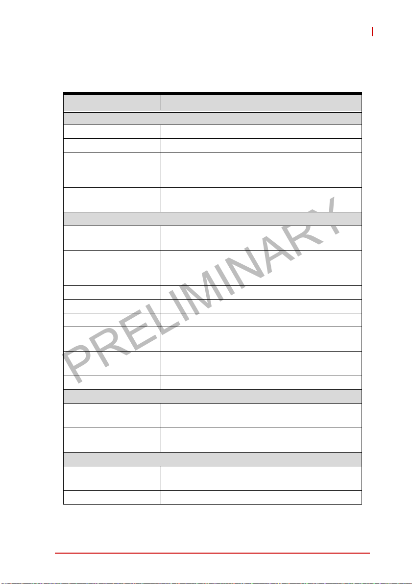
1.3 Specifications
MXE-5401
System
Processor Intel® Core™ i7-4700EQ
Chipset Intel
Video
Memory
I/O Interface
Ethernet
Serial Ports
USB 6 USB 3.0 ports + 1 internal USB 2.0 port
DI/O 8 DI/O w/ 1.5KV isolation
Audio 1 mic-in and 1 line-out
Mini PCIe
USIM
WDT Supports watchdog timer via SEMA
Power Supply
DC Input
AC Input
Storage
SATA HDD
CompactFlash 1 CFAST slot, supporting PIO and DMA modes
®
Mobile Platform Controller Hub (QM87)
3 independent displays out of 4 channels
1x VGA+ DVI by DVI-I connector
2x Dual Mode DisplayPort
4 GB DDR3L 1600 MHz SODIMM module (Up to
16 GB support)
®
4 GbE ports (3x Intel
PHY)
2 BIOS configurable RS-232/422/485 (COM1 &
COM2)
2 RS-232 (COM3 & COM4)
2 internal PCIe mini card sockets w/ 1 mSATA
support
1 USIM socket for 3G communication (for 3G-mini
module)
Built-in 9-32 VDC wide-range DC input
3P pluggable connectors with latch (GND, V-, V+)
Optional 160 W external AC-DC adapter for AC
input
2 onboard SATA-III port for 2.5" HDD/SSD
installation (supports RAID 0,1)
I210IT + 1 Intel® I217LM
Introduction 3
Page 16
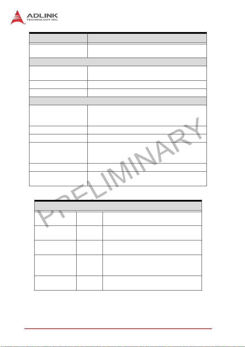
PRELIMINARY
MXE-5401
eSATA
Mechanical
Dimensions
Weight 3.8 kg (8.39 lb)
Mounting Wall-mount kit
Environmental
Operating Temperature
Storage Temperature -40°C to 85°C (excl. HDD/SDD/CFAST)
Humidity Approx. 95% @ 40°C (non-condensing)
Vibration
ESD Contact +/-4 KV and Air +/-8 KV
Shock
Power Consumption
Power off 2.16 W
System Idle 13.44 W
Processor full
load
System full load 92.4 W
Recommended
power supply
1 eSATA interface connectors on rear panel for
storage expansion
230 mm (W) x 205 mm (D) x 75 mm (H) (9” x 8” x
2.5”)
Standard: 0°C to 50°C
Extended temperature: -20°C to 60°C (w/
industrial SSD or CFAST)
Operating, 0.5 Grms, 5-500 Hz, 3 axes (w/ HDD)
Operating, 5 Grms, 5-500 Hz, 3 axes (w/ SSD,
CFast)
Operating, 50 G, half sine 11 ms duration (w/
CFAST or SSD)
In shutdown mode with DC input and
only USB keyboard/mouse
Under Windows Desktop with no
application programs executed
47.04 W
160W
Under Windows with 100% CPU
utilization and 2D/3D graphics load
Under Windows with 100% CPU
utilization and simultaneous access to all
I/O devices.
With consideration of voltage de-rating
under high environmental temperature.
4Introduction
Page 17
PRELIMINARY
MXE-5400
DDR 3 L
SO - D I MM
DDR 3 L
SO - D I MM
Di spl ay
Po r t 2
Di spl ay
Po r t 1
DVI - I
SATA
SSD1
SATA
SSD2
USB3 . 0
Po r t 1
USB3 . 0
Po r t 1
USB3 . 0
Po r t 1
USB3 . 0
Po r t 1
USB3 . 0
Po r t 1
USB3 . 0
Po r t 1
Ch ron t e l
CH 7 3 1 8
VGA
SATA3( 0 )
SATA3( 1 )
USB3( 1 ) / USB2 (0 )
USB3( 2 ) / USB2 (1 )
USB3( 3 ) / USB2 (2 )
USB3( 4 ) / USB2 (3 )
USB3( 5 ) / USB2 (4 )
USB3( 6 ) / USB2 (5 )
SUMIT CONN_X4 PCIE2(4~7)
Ch an ne l A
Ch an ne l B
USB2 (8 )
USB2 (9 )
Rea lt ek
ALC269Q
DDP D
DDP C
DDP BDVI
USB2 . 0
Po r t 1
USB2 . 0
Po r t 2
HDA
Intel
Haswel l (BGA1364
I7-4700EQ 2.4GHz
/I5-4400E 2.7GHz
/I3-4100E 2.4GHz
Intel
Lyn x Po i n t QM87
QM 8 7 C h i p s e t
Figure 1-1: MXE-5400 Functional Block Diagram
1.4 Unpacking Checklist
SATA2( 2 )
SMBusPCI E2 ( 3 )SUM IT CONN_X1
DMIInte l FDI
TPM
AT97SC3204
CFAST slot
SEMA BMC
PC I E3 ( X 8 )
PC I E3 ( X 4 )
PC I E3 ( X 4 )
)
PCIE2(2)
USB2 ( 1 0 )
PCIE2(1) /SATA3 (5)
USB2 ( 1 1 )
LPC
SIO
ITE8786E
Dig i tal IO
8in/out(Isolation)
LAN2I210IT
LAN3I210IT
LAN4I210IT
LAN1- I2 17 -LM
(CLARKVILLE)
MINI PCIE1PCIE2(0)
MINI PCIE2
/ mSATA
COM1
RS-232/422/485
COM2
RS-232/422/485
COM3
RS23 2
COM4
RS23 2
USIM
Before unpacking, check the shipping carton for any damage. If
the shipping carton and/or contents are damaged, inform your
dealer immediately. Retain the shipping carton and packing
materials for inspection. Obtain authorization from your dealer
before returning any product to ADLINK. Ensure that the following items are included in the package.
X MXE-5400 unit
X Screw pack for wall-mounting and HDD installation
X DB62 to COM/DIO splitter cable
X Quick Start Guide
X ADLINK All-in-One DVD
Introduction 5
Page 18
PRELIMINARY
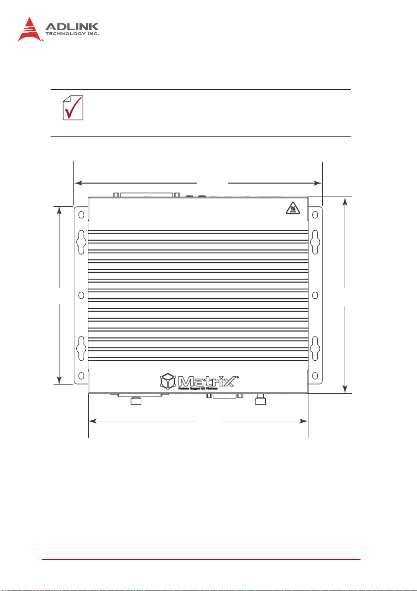
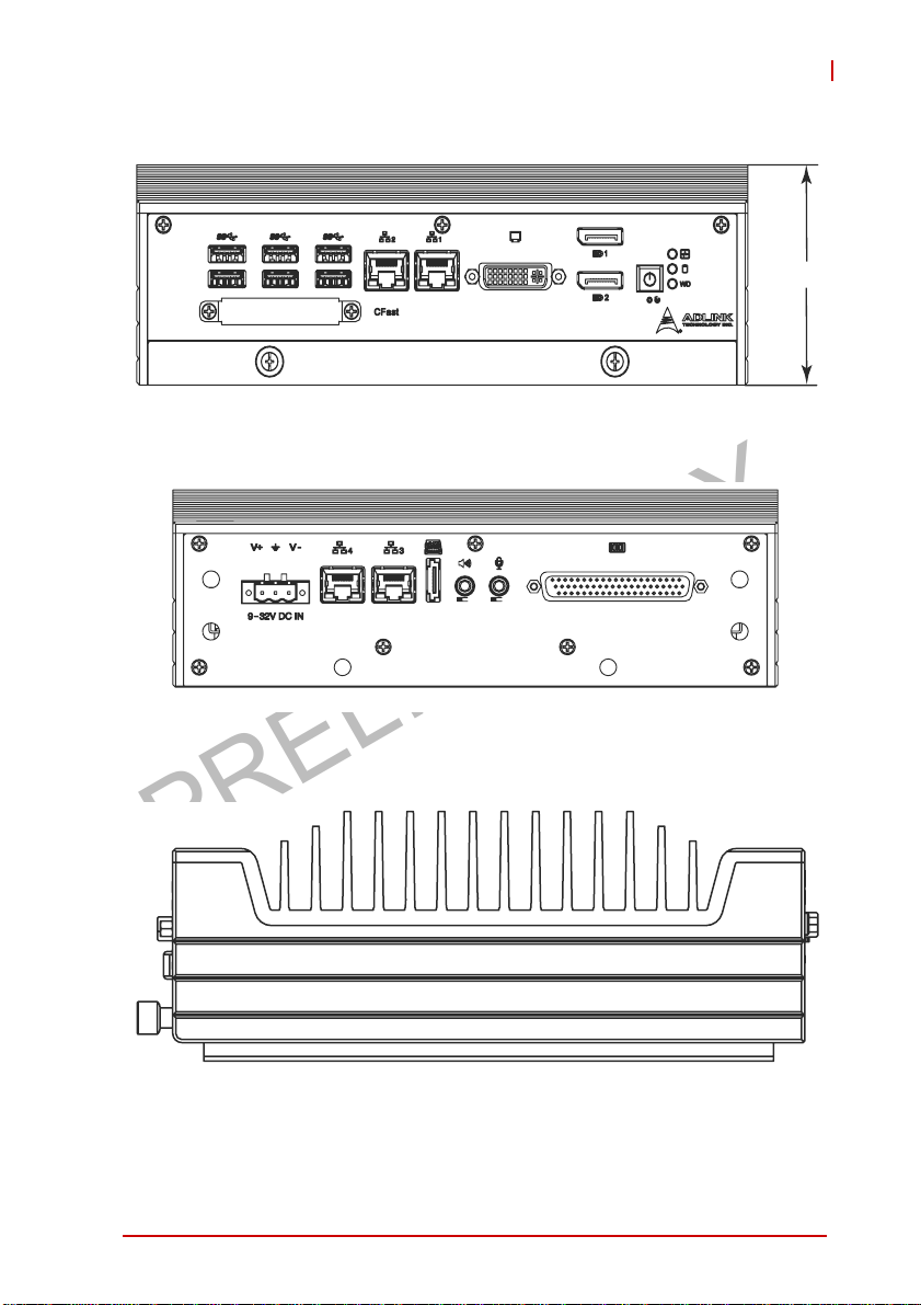
1.5 Mechanical Drawings
All dimensions shown are in millimeters (mm) unless otherwise
stated.
NOTE:
NOTE:
259.2
185
230
Figure 1-2: Top View
6Introduction
205.2
Page 19
PRELIMINARY
Figure 1-3: Front View
MXE-5400
63
Figure 1-4: Rear View
Figure 1-5: (Left) Side View
Introduction 7
Page 20
PRELIMINARY
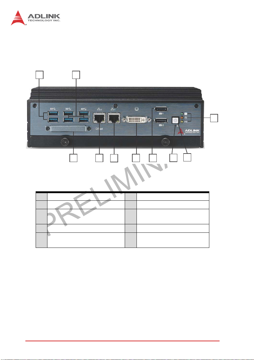
1.6 Front Panel I/O Connectors
This section describes the I/O connectors located on the front
panel of the MXE-5400.
I J
B
D
H
A LED indicators F I217 Gigabit Ethernet port
B Power button G I210 Gigabit Ethernet port
C Reset button H
D Dual DisplayPort connector I Dual USB 3.0 port
E DVI-I connector J
Table 1-1: MXE-5400 Front Panel I/O Connector Legend
G
F
Figure 1-6: Front Panel I/O
E
CFast connector
(Push-Push, Type II)
Dual USB 3.0 ports
(1600mA supported)
C
A
1.6.1 Power Button
The power button is a non-latched push button with a blue LED
indicator. System is turned on when button is pressed, and the
power LED lit. If the system hangs, depressing the button for 5
seconds powers down the system.
8Introduction
Page 21

PRELIMINARY
MXE-5400
1.6.2 LED Indicators
In addition to the LED of the power button, three LEDs on the front
panel indicate the following operations.
Indicator Color Description
Indicates watchdog timer status.
Watchdog (WDT) Yellow
Hard disk drive Orange
Diagnostic Green
T able 1-2: LED Indicators
1.6.3 Reset Button
The reset button executes hard reset for the MXE-5400.
Flashes when watchdog timer starts,
and when timer is expired, system will
auto-reboots.
When blinking, indicates the SATA hard
driver is active
If lit continuously, indicates no physical
storage is connected.
If blinking, indicates no memory is
installed on either SO-DIMM socket.
Introduction 9
Page 22
PRELIMINARY
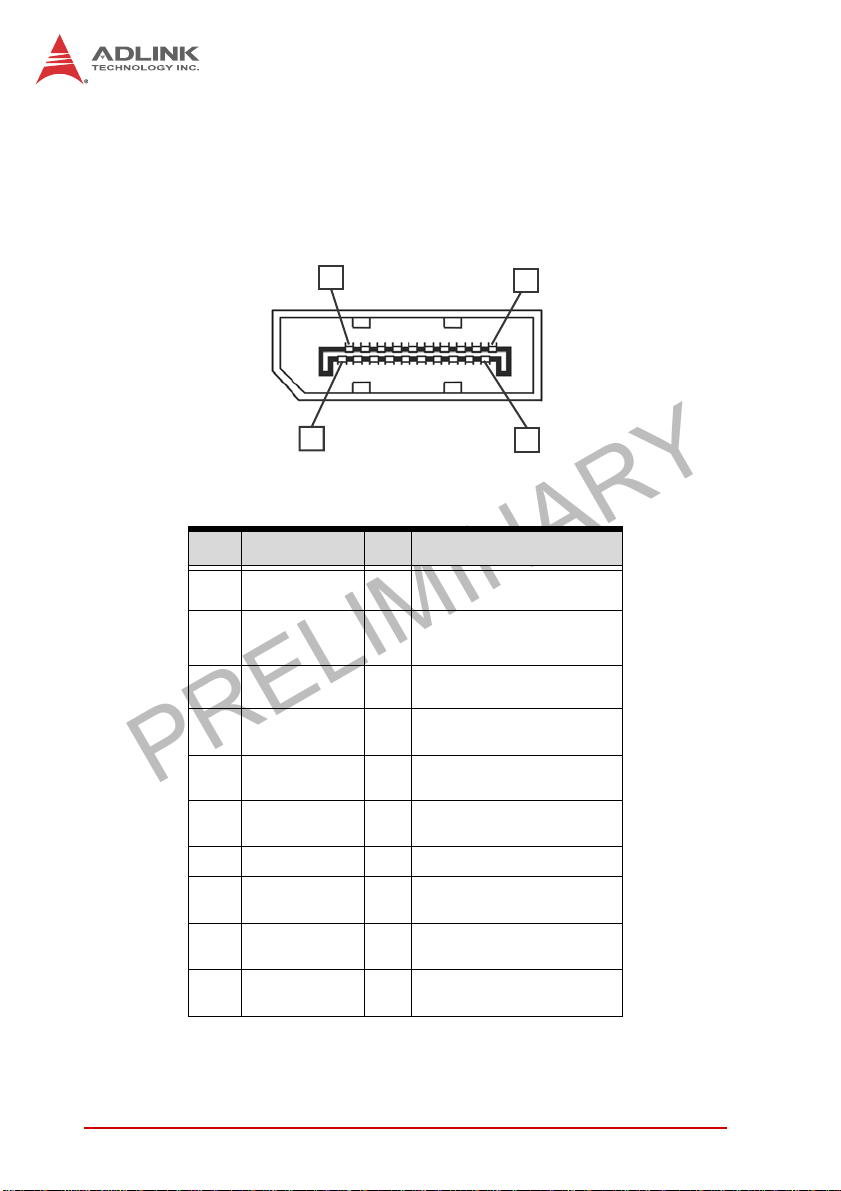
1.6.4 Dual DisplayPort Connector
A dual DisplayPort connector on the front panel provides connection to VGA, DVI, HDMI monitor via DisplayPort to VGA adapter
cable, to DVI adapter cable, and to HDMI adapter cable.
19
20
Pin Signal Pin Signal
1 CN_DDPx0+ 11 GND
2 GND 12 CN_DDPx3-
3 CN_DDPx0- 13 CN_DDPx_AUX_SEL
4 CN_DDPx1+ 14 CN_DDPx_CONFIG2
5 GND 15 CN_DDPx_AUX+
6 CN_DDPx1- 16 GND
1
2
7 CN_DDPx2+ 17 CN_DDPx_AUX-
8 GND 18 CN_DDPx_HPD
9 CN_DDPx2- 19 GND
10 CN_DDPx3+ 20 +V3.3_DDPx_PWR
Table 1-3: DisplayPort Pin Assignment
10 Introduction
Page 23
PRELIMINARY
MXE-5400
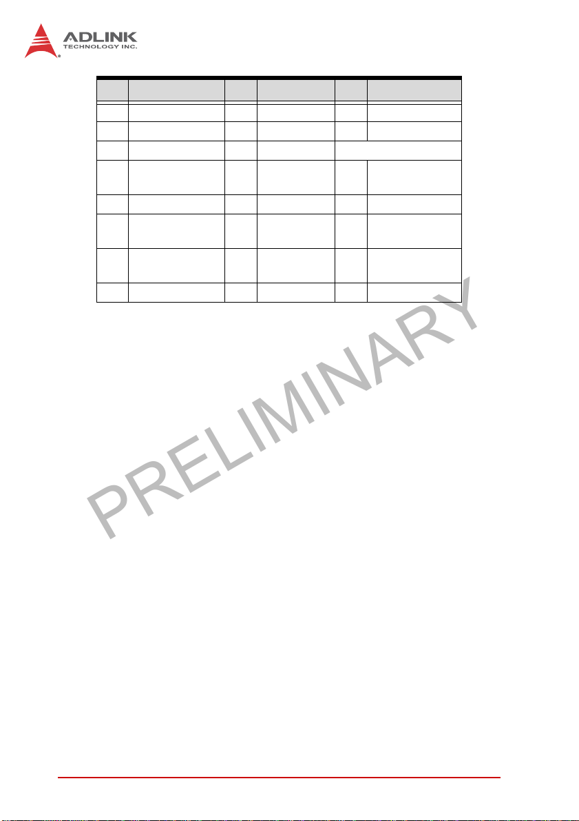
Multi-Display Option
With the computing and graphic performance enhancements of
4th generation Intel processor, the MXE-5400 fully supports three
independent displays, configured as follows.
Display 1 DP DP DVI
Display 2 DP DP VGA
Display 3 DVI VGA DP
Max. Res
Display1
Max. Res
Display2
Max. Res
Display3
2560 x 1600
@60Hz
2048 x 1152
@60Hz
Table 1-4: Multi-Display Configuration
2560 x 1600
@60Hz
2048 x 1280
@60Hz
2048 x 1152
@60Hz
2048 x 1280
@60Hz
2560 x
1600@60Hz
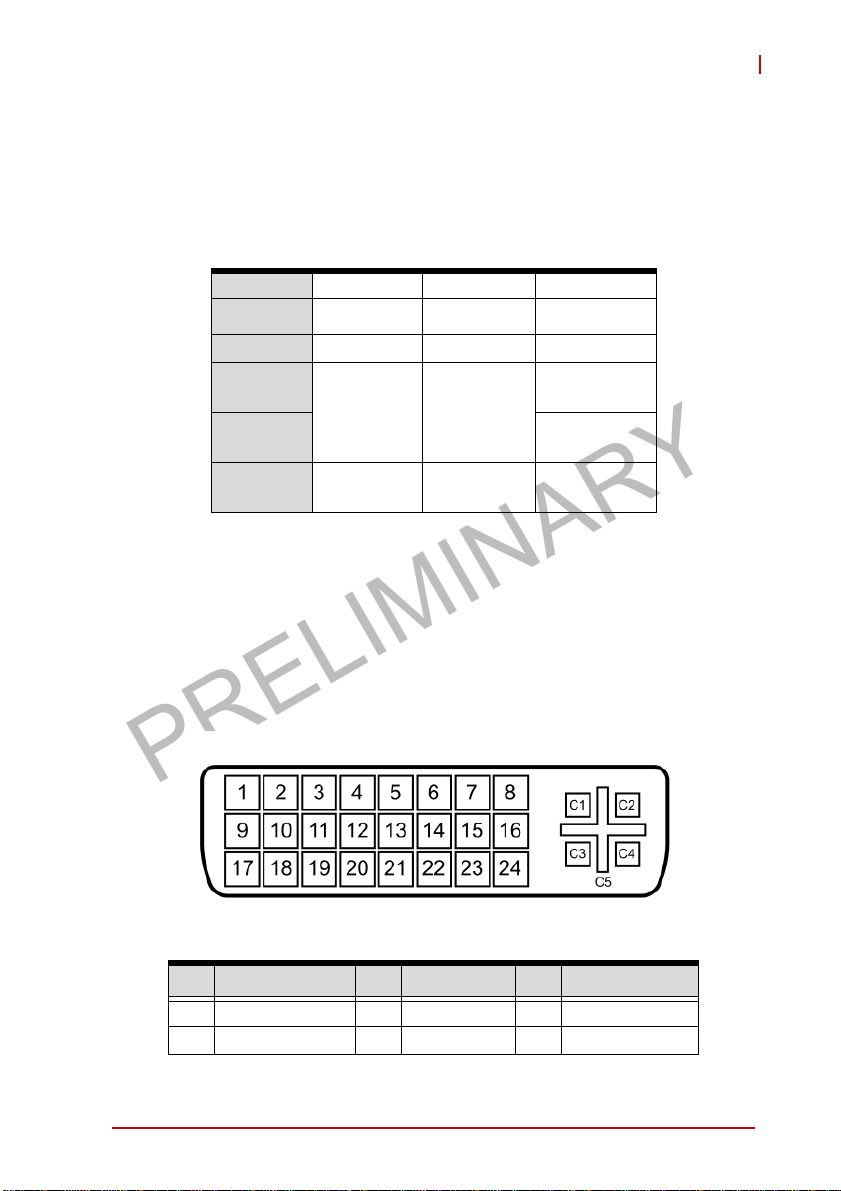
1.6.5 DVI-I Connector
The MXE-5400 provides a DVI-I connector for connection to external monitor, which can separate to individual VGA and DVI-D (single link) interfaces.
Pin Signal Pin Signal Pin Signal
1 DVI_Data2- 11 GND 21 N/C
2 DVI_Data2+ 12 N/C 22 GND
Introduction 11
Page 24
PRELIMINARY
Pin Signal Pin Signal Pin Signal
3 GND 13 N/C 23 DVI clock+
4 CRT DDC clock 14 +5V 24 DVI clock-
5 CRT DDC data 15 GND
6 DVI DDC clock 16
7 DVI DDC data 17 DVI_Data0- C2 Analog Green
Analog vertical
8
sync
9 DVI_Data1- 19 GND C4
10 DVI_Data1+ 20 N/C C5 Analog GND
Table 1-5: DVI-I Connector Pin Assignment
Hot plug
detect
18 DVI_Data0+ C3 Analog Blue
C1 Analog Red
Analog
/horizontal sync
12 Introduction
Page 25

PRELIMINARY
MXE-5400
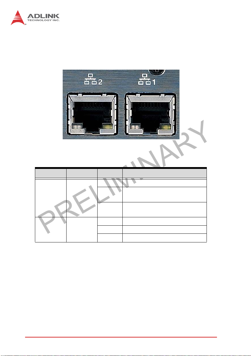
1.6.6 Dual Gigabit Ethernet Ports
The two Gigabit Ethernet ports consist of an Intel WGI210IT GbE
controller and a WGI217LM Gigabit Ethernet PHY.
The WG210IT supports:
X IEEE 802.3az Energy Efficient Ethernet
X IEEE 1588/802.1AS precision time synchronization
X IEEE 802.3av traffic shaper
X Interrupt moderation, VLAN support, IP checksum offload
X PCIe OBFF (Optimized Buffer Flush/Fill) for improved sys-
tem power management
X Four transmit and four receive queues
X RSS and MSI-X to lower CPU utilization in multi-core sys-
tems
X ECC - error correcting memory in packet buffers
X Wake-On-LAN
X NC-SI for greater bandwidth passthrough
X SMBus low-speed serial bus to pass network traffic
X Preboot eXecution Environment (PXE) flash interface sup-
port
X Jumbo frame support
X LAN Teaming
The WGI 217LM supports:
X IEEE 802.3u auto-negotiation conformance
X Energy Efficient Ethernet (EEE) IEEE 802.3az support [Low
Power Idle (LPI) mode]
X Energy Efficient Ethernet(EEE)802.3az
X 10/100/1000 IEEE 802.3-compliant
X Automatic MDI/MDIX crossover at all speeds
X Wake-On-LAN
X Intel® AMT 9.0
X Reduced power consumption during normal operation and
power down modes
Introduction 13
Page 26
PRELIMINARY
X Preboot eXecution environment (PXE) flash interface
X 9 KB jumbo frame support
X LAN Teaming
Figure 1-7: Gigabit Ethernet Ports
LED LED Color Status Description
OFF Ethernet port is disconnected
Ethernet port is connected with no
activity
Ethernet port is connected and
active
Active/Link Yellow
Speed
Green/
Orange
Table 1-6: Gigabit Ethernet Port LED Function
ON
Flashing
OFF 10 Mbps
Green 100 Mbps
Orange 1000 Mbps
1.6.7 USB 3.0 Ports
The six USB 3.0 ports supporting Type A connection are all compatible with SuperSpeed, Hi-Speed, full-speed and low-speed
USB devices, with support for multiple boot devices, including
14 Introduction
Page 27
PRELIMINARY
MXE-5400
USB flash, USB external HDD, and USB CD-ROM drivers and
boot priority and boot device configured in BIOS.
X When using USB CD-ROM via USB 3.0 port to
re-install or repair the OS, cold boot should be
NOTE:
NOTE:
utilized
X Four USB 3.0 ports support additional current up
to 1600mA, positioned as shown in Table 1-1 on
page 8
1.6.8 CFast Port
A type II push-push CFast host connector on the front panel connects to the host controller by SATA interface, with data transfer
rates up to 3.0Gb/s(300MB/s)/1.5Gb/s(150MB/s) supported.
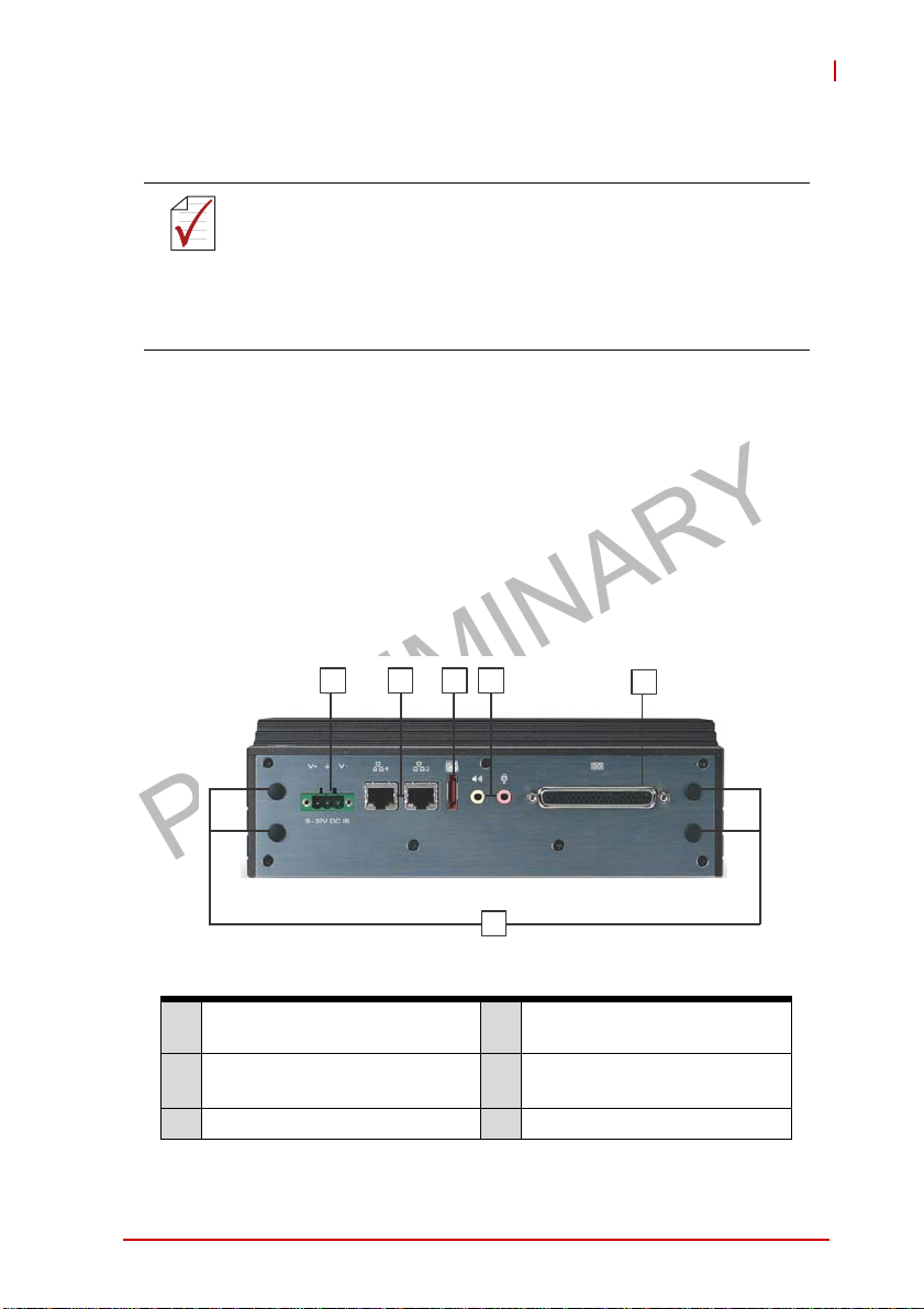
1.7 Rear Panel I/O Connectors
This section describes I/O connectors located on the rear panel of
the MXE-5400.
CDEF
A
Figure 1-8: Rear Panel I/O
Antenna connection plugs
A
(X4)
DB-62P COM ports and digital
B
I/O connector
C Audio jacks F DC power supply connector
Table 1-7: MXE-5400 Rear Panel I/O Connector Legend
Introduction 15
D eSATA connector
I210 Gigabit Ethernet ports
E
(X2)
B
Page 28

PRELIMINARY
1.7.1 DB-62P COM Port and Digital I/O Connector
4 COM ports and 8-channel isolated digital input and 8-channel
isolated digital output are provided by the DB-62P connector with
the included cable, terminating in four D-SUB 9-pin connectors
and one 26-pin digital I/O connector. COM1 and COM2 ports
selectively support RS-232/ RS-422/ RS-485 according to BIOS
setting. Residual COM3 and COM4 ports support only RS-232
function.
21
42
62
Figure 1-9: DB-62P COM Port
Pin Signal Pin Signal Pin Signal
1 COM3_TXD 22 N/C 43 N/C
2 COM3_DTR# 23 COM3_DSR# 44 COM3_RTS#
3 COM3_RI# 24 COM3_DCD# 45 GND
4 COM4_TXD 25 COM4_RXD 46 COM4_CTS#
5 COM4_DTR# 26 COM4_DSR# 47 COM4_RTS#
6 COM4_RI# 27 COM4_DCD# 48 GND
7 COM1_TXD 28 COM1_RXD 49 COM1_CTS#
8 COM1_DTR# 29 COM1_DSR# 50 COM1_RTS#
1
43
22
9 COM1_RI# 30 COM1_DCD# 51 GND
10 COM2_TXD 31 COM2_RXD 52 COM2_CTS#
16 Introduction
Page 29

PRELIMINARY
MXE-5400
Pin Signal Pin Signal Pin Signal
11 COM2_DTR# 32 COM2_DSR# 53 COM2_RTS#
12 COM2_RI# 33 COM2_DCD# 54 GND
13 IDI_67L 34 IDI_7H 55 IDI_0H
14 IDI_5H 35 IDI_6H 56 IDI_0L
15 IDI_4H 36 IDI_45L 57 IDI_1H
16 IDI_3H 37 IDI_3L 58 IDI_1L
17 EOGND 38 IDI_2L 59 IDI_2H
18 IDO_6 39 IDO_7 60 +V5DIO_ISO
19 IDO_4 40 IDO_5 61 +VDD
20 IDO_2 41 IDO_3 62 +VDD
21 IDO_0 42 IDO_1 N/C
Table 1-8: DB-62P COM Port Pin Assignment
1 5
6
Figure 1-10: D-SUB 9P COM Connector
Introduction 17
9
Page 30

PRELIMINARY
Pin Signal
RS-232 RS-422 RS-485
1 DCD# TXD422- 485DATA-
2 RXD TXD422+ 485DATA+
3 TXD RXD422+ N/C
4 DTR# RXD422- N/C
5 GND N/C N/C
6DSR# N/C N/C
7RTS# N/C N/C
8CTS# N/C N/C
9 RI# N/C N/C
Table 1-9: D-SUB 9P COM Pin Assignment
8CH Isolated DI 8CH Isolated DO
Logic high: 5 to 24 V
Logic low: 0 to 1.5 V
Input resistance: 8.2 k @ 0.5 W Supply voltage: 5 to 35 VDC
Interrupt source: DI
Isolation voltage: 1.5KV DC
channel 0 to 7
Output: Open Drain N- Channel
Power MOSFET driver
250 mA for all channels @ 60°C,
100% duty
Isolation voltage: 1.5KV DC
channel 0 to 7
200 mA for +V5DIO_ISO (max)
Table 1-10: Digital I/O Specifications
18 Introduction
Page 31

PRELIMINARY
MXE-5400
18
9
26
Figure 1-11: D-SUB 26P Connector on Digital I/O Port
Pin Signal Pin Signa Pin Signal
1 EOGND 10 IDO_0 19 IDI_3H
2 +V5DIO_ISO 11 EOGND 20 IDI_2L
3 IDO_7 12 IDI_7H 21 IDI_2H
4 IDO_6 13 IDI_67L 22 IDI_1L
5 IDO_5 14 IDI_6H 23 IDI_1H
6 IDO_4 15 IDI_5H 24 IDI_0L
7 IDO_3 16 IDI_45L 25 IDI_0H
8 IDO_2 17 IDI_4H 26 N/C
9 IDO_1 18 IDI_3L
19
1
10
Table 1-11: D-SUB 26P Pin Assignme nt on Digital I/O Port
Isolated Digital Input Circuits
The input can accept voltages up to 24V, and input resistors are
8.2KΩ. Connections between outside signals are as follows.
IDI_nH
ISO_COM
R67 0 8.2 K_+ -5 %08.2K_+-5%
1
D20
D20
1
2
TVS
TVS
2
1 1
2
2
Figure 1-12: Isolated Digital Input Circuit
Introduction 19
4
4
3
3
DI
GND
Page 32

PRELIMINARY
IDI_nH
IDI_nL
Power
R671 8.2K_+-5%R671 8.2K_+-5%
D21
D21
TVS
TVS
IDI_6 7L
1 1
1
1
2
2
2
2
4
4
3
3
Figure 1-13: Isolated/Differential Digital Input Circuit
DI
GND
4
4
3
3
GND
ISO_COM
8.2 K _+ -5 %8.2 K _+ -5 %
D20
D20
TVS
TVS
1 1
1
1
2
2
2
2
Power
IS 1IS 1
4
4
3
3
GND
ISO_COM
R670 8.2 K_+-5%R670 8.2 K_+-5%
D20
D20
TVS
TVS
1 1
1
1
2
2
2
2
Figure 1-14: Isolated Digital Input Sample Application Circuit
20 Introduction
DI
DI
Page 33

PRELIMINARY
MXE-5400
Isolated Digital Output Circuits
Each isolation digital output channel adopts a MOSFET transistor,
capable of driving peak current up to 250mA (sustained current up
to 100 mA) with voltage ranges from 5V to 35V.
The VDD pin is connected in serial with a fly-wheel diode to protect the driver during inductance loading, such as relay, motor, or
solenoid. The VDD must connect to external power to form a
fly-wheel current loop.
+VDD
D29
D29
BAV99
BAV99
DO_n IDO_n
R682 680 R3R682 680 R3
4
4
6
6
3
3
MO S F E T S i 9 9 4 5 BD Y - T 1- G E 3 N- C HMO S F E T S i 9 9 4 5 BD Y - T 1- G E 3 N- C H
C606 C15 N50 VKX7C606 C15 N50 VKX7
EOG ND
5
5
Figure 1-15: Isolated Digital Output Circuits
D29
D29
BAV99
BAV99
6
6
5
5
Load
+
-
DC
(5 to 35V)
R682 680R3R682 680R3
EOGND
Q2 6B
Q2 6B
4
4
3
3
MOS FET Si9945BDY -T1-GE3 N-CH
MOS FET Si9945BDY -T1-GE3 N-CH
C606 C15N50VKX7C606 C15N50VKX7
Figure 1-16: Isolated Digital Output Sample Application Circuit
Introduction 21
Page 34

PRELIMINARY
1.8 Internal I/O Connectors
I
J
A
B
C
Figure 1-17: Internal I/O
GH
F
E
D
A Internal USB 2.0 wafer (reserved)
B Controls CN23 function
C Clear CMOS jumper
D SATA slots (X2)
E USIM slot
F DC 5V and 3.3V connectors for GPS module
G Mini PCIe slot
H Mini PCIe/mSATA slot
I USB 2.0 connector
J Extended Power/Reset/LED wafer
Table 1-12: MXE-5400 Internal I/O Legend
22 Introduction
Page 35

PRELIMINARY
MXE-5400
1.8.1 Clear CMOS Jumper
Under conditions in which the MXE-5400 fails to boot, clearing the
BIOS content stored in CMOS and restoring the default settings
may be effective. To clear CMOS, short Pin#1 and Pin#2 of CN3
and remove the jumper, after which the CMOS will be restored to
factory default settings.
Normal Clear
1
2
CN3 CN4
Figure 1-18: Clear CMOS Jumper Pin Settings
T able 1-13: Clear CMOS Jumper Pin Assignment
1.8.2 DC 5V and 3.3V Connectors for GPS Module
The two power connectors, for GPS module use, carry a maximum current rating of 1A each.
1
2
1
2
CN3 CN4
Pin Description
1 RTCRST#
2Gnd
1
2
Introduction 23
Page 36

PRELIMINARY
2
1
2
1
Figure 1-19: DC 5V and 3.3V Connectors Configuration
Pin Description
CN19
1+5V
2Gnd
CN20
1 +3.3V
2Gnd
T able 1-14: DC 5V and 3.3V Connectors Pin Assignments
CN19
CN20
1.8.3 USIM Port
Use of 3.5G mini-PCIe module requires a SIM card for communication with a telecom operator. The MXE-5400 provides a USIM
port connected to the mini-PCIe connector, with which a SIM card
and 3.5G mini-PCIe module can be installed to facilitate 3.5G
communication.
1.8.4 SATA Connectors (X2)
The SATA connectors support data transfer up to 6.0Gb/s(600MB/
s), with a SATA host controller supporting legacy mode using I/O
space and AHCI mode using memory space. The SATA connector
is compatible with a 2.5in. hard disk drive (HDD) or solid state disk
24 Introduction
Page 37

PRELIMINARY
MXE-5400
2
2
3
(SSD), requiring installation into the SATA connector with a HDD
bracket.
1.8.5 Mini-PCIe Connectors
The MXE-5400 features two mini-PCIe connectors, following the
revision 1.2 standard. While both CN16 and CN 23 support versatile mini-PCIe modules, the USIM slot is set to interact with CN16,
accepting WWAN modules. In addition to mini PCIe support,
CN23 provides mini SATA access via jumper CN24 selection, as
shown.
mSATA Mini-PCIe
123
Figure 1-20: Mini-PCIe Connector Jumper Settings
123
Introduction 25
Page 38

PRELIMINARY
1.8.6 Extendable Power/Reset/LED
The MXE-5400 provides internal LED connectors powering indicators for the Power button (from CN40), Reset button (CN39), and
Power for external controllable devices (CN41), assigned as
shown.
1
2
1
2
1
2
CN39 CN41 CN40
Figure 1-21: Extendable Power/Reset/LED Configuration
Pin Description
CN40
1 Power Button
2Gnd
CN41
1 +V3.3SB
2 Power LED
CN39
1 Reset Button
2Gnd
Table 1-15: Extendable Power/Reset/LED Connectors Pin Assignments
26 Introduction
Page 39

PRELIMINARY
2 Getting Started
This chapter discusses installation of hard disk drive, mini-PCIe
module, mSATA, and CFast card. In addition to connection and
use of DIO and COM ports, wall-mount installation is also
described.
2.1 Installing Hard Disk Drives
The MXE-5400 provides two SATA connectors for installation of
one hard disk drive each.
1. Remove the thumbscrews on the front panel by hand or
screwdriver.
MXE-5400
2. Withdraw the thumbscrews and remove the bottom
cover by pulling and lifting.
Getting Started 27
Page 40

PRELIMINARY
28 Getting Started
Page 41

PRELIMINARY
MXE-5400
3. Place the two HDD brackets on left and right sides of a
2.5’’ HDD or SSD and use the 4 M3-F-head-L4 screws to
fix the brackets.
Getting Started 29
Page 42

PRELIMINARY
4. Install the hard disk drive and fasten the 2 M3-head-L4
screws on the top of the HDD brackets. Two hard disk
drives are supported.
5. Re-assemble the bottom cover and fasten the thumbscrews on the front panel by hand or screwdriver.
30 Getting Started
Page 43

PRELIMINARY
MXE-5400
2.2 Installing a Mini-PCIe Device
The MXE-5400 provides two mini-PCIe slots supporting mini-PCIe
wireless modules and mSATA devices.
1. Remove bottom cover as detailed previously.
2. Insert the mini-PCIE wireless module into the slot at an
angle.
3. Depress the mini-PCIe wireless module into place and
use the 2 M2.5-P-head-L5 screws to fix the module.
Getting Started 31
Page 44

PRELIMINARY
For details of Mini SATA connection, please see “Mini-PCIe Connectors” on page 25.
32 Getting Started
Page 45

PRELIMINARY
MXE-5400
2.3 Internal USB Connector
The MXE-5400 provides an internal USB2.0 connector to accommodate one USB dongle.
Use the M2.5-I-head-L4 screw and USB bracket included in the
accessory package to fix the USB dongle.
Getting Started 33
Page 46

PRELIMINARY
2.4 Installing CFast Card
The MXE-5400 provides an external CFast socket to accommodate one CFast card for additional storage.
1. Remove the 2 screws and the CFast cover from the front
panel.
34 Getting Started
Page 47

PRELIMINARY
2. Gently insert the CFast card into the CFast socket.
MXE-5400
3. Re-assemble the CFast cover and fasten the 2 screws
on the front panel.
Getting Started 35
Page 48

PRELIMINARY
2.5 COM Ports and DIO Device
4 COM ports, 8 digital input and 8 digital output ports are available
on the included breakout cable, for connecting COM ports and
DIO devices.
Connect the cable to the connector on the rear panel.
The 4 COM port cables are numbered 1 to 4, with 1 and 2 (COM1
& COM2) BIOS configurable and connecting to RS-232/422/485
devices and 3 and 4 (COM3 & 4) to RS-232 interface devices.
Cable #
COM1 1 Yes
COM2 2 Yes
36 Getting Started
BIOS
configurable
Device Compatibility
RS-232/422/485
Page 49

PRELIMINARY
MXE-5400
Cable #
COM3 3 No
COM4 4 No
The DIO cable connects to a terminal board for digital input and
digital output.
BIOS
configurable
Device Compatibility
RS-232
ADLINK provides the following optional accessories:
X DB26-to-DIN37 cable (Part Number
NOTE:
NOTE:
Getting Started 37
30-01143-0000)
X DIN37 terminal board (Part Number
91-14025-1020)
Page 50

PRELIMINARY
2.6 Connecting DC power
Before introducing DC power to the MXE-5400, ensure the
voltage and polarity provided are compatible with the DC input.
WARNING:
The DC power input connector of the MXE-5400 utilizes V+, V- ,
and chassis ground pins, and accepts input voltage as shown previously.
Improper input voltage and/or polarity can be responsible for
system damage.
1. Connect DC power.
2. Fix the DC connector using the 2 screws.
2.7 Wall-mounting the MXE-5400
The MXE-5400 is shipped with wall-mount brackets and accessory screws, with mounting procedures as follows.
1. Prepare the two wall-mount brackets and 4 M4-P head
screws included in the package.
38 Getting Started
Page 51

PRELIMINARY
MXE-5400
2. Remove the 4 plastic pads from the corners of the chas-
sis underside.
Getting Started 39
Page 52

PRELIMINARY
3. Fix the 2 wall-mount brackets, also included, to the chassis with the 4 included M4-P head screws, according to
the spacing dimensions of the screw holes and brackets,
as shown. (All units are in millimeters (mm)
40 Getting Started
Page 53

PRELIMINARY
MXE-5400
4. Once final assembly as shown is complete, mount the
MXE-5400 series controller on the wall via the screw
holes.
2.8 Cooling Considerations
Heat-generating components of the MXE-5400 (such as CPU and
PCH) are all situated on the left side of the system. These components directly contact the heat sink via thermal pads and dissipate
heat generated by the components. To maximize efficiency of heat
dissipation, maintain a minimum of 2 inches (5 cm) clearance on
the top of the MXE-5400.
Getting Started 41
Page 54

PRELIMINARY
This page intentionally left blank.
42 Getting Started
Page 55

PRELIMINARY
3 Driver Installation
After installing the operating system, all related drivers must be
installed for the system to function properly. This section describes
the drivers needed for Windows operating systems and the
procedures to install them. For other OS support, please contact
ADLINK for further information.
Install drivers as follows.
1. Fully install Microsoft Windows OS before installing any
drivers. Most standard I/O device drivers have been
included in Microsoft Windows OS. For Windows 7
users, please note that you need Administrator privilege
to install the drivers properly.
2. Install the chipset driver.
3. Install the graphics driver.
4. Install the Ethernet driver.
5. Install the audio driver.
6. Install the SEMA utility, WDT and DI/O drivers.
MXE-5400
3.1 Installing the Chipset Driver
This section describes installation of the chipset driver for the
MXE-5400. The chipset driver directs the operating system to configure the Intel
the following features function properly:
X SATA Storage Support
X USB Support
X Identification of Intel
Manager
Microsoft Windows 7 must be fully installed and running on the
system before installing this software:
The following steps install the chipset driver for the MXE-5400
1. Close any running applications.
2. Insert the ADLINK All-in-One DVD. The chipset driver is
located in the directory
Driver Installation 43
®
QM87 chipset components in order to ensure that
®
Chipset Components in the Device
Page 56

PRELIMINARY
x:\Driver Installation\Matrix\MXE-5400\Chipset
where x: denotes the DVD-ROM drive.
3. Execute Setup.exe and follow onscreen instructions to
complete the setup.
4. After installation is complete, reboot the system.
3.2 Installing the Graphics Driver
This section describes installation of the graphics driver for the
MXE-5400. The MXE-5400 is equipped with the Intel
Media Accelerator Driver package, which supports Windows 7.
To install the graphics driver:
1. Close any running applications.
2. Insert the ADLINK All-in-One DVD. The graphics driver
is located in the directory
x:\Driver Installation\Matrix\MXE-5400\Graphics
where x: denotes the DVD-ROM drive.
3. Execute Setup.exe and follow onscreen instructions to
complete the setup.
4. After installation is complete, reboot the system.
®
Graphics
3.3 Installing the Ethernet Driver
This section describes installation of the Ethernet driver for the
MXE-5400. To install the driver for the Intel 1210/1217 Gigabit
Ethernet controller:
1. Close any running applications.
2. Insert the ADLINK All-in-One DVD. The Ethernet driver
is located in the directory
x:\Driver Installation\Matrix\MXE-5400\LAN-Intel\
where x: denotes the DVD-ROM drive.
3. Execute setup.exe and follow onscreen instructions to
complete the setup.
4. After installation is complete, reboot the system.
44 Driver Installation
Page 57

PRELIMINARY
MXE-5400
3.4 Installing the Audio Driver
This section describes installation of the audio driver for the
MXE-5400. The MXE-5400 supports High Definition audio using
the Realtek ALC269 audio codec. To install the audio driver:
1. Close any running applications.
2. Insert the ADLINK All-in-One DVD. The audio driver is
located in the directory
x:\Driver Installation\Matrix\MXE-5400\Audio\
where x: denotes the DVD-ROM drive.
3. Execute Setup.exe and follow onscreen instructions to
complete the setup.
4. After installation is complete, reboot the system.
3.5 Installing the SEMA utility, WDT and DI/O Drivers
This section describes installation of the SEMA utility, WDT and
DI/O drivers for the MXE-5400.
The MXE-5400 supports ADLINK Smart Embedded Management
Utility with features as follows.
X System Health for real time CPU, system temperature,
total/current uptime
X User-defined 1KB Flash
X Watchdog Timer
X Hardware Monitoring for input voltage levels and current
power consumption
X Digital Input/Output control utility (sample)
X S.M.A.R.T. Information for storage
A WDT (watchdog timer) is a hardware mechanism resetting the
system when the operating system or application is halted. A typical usage of WDT is to start the timers and periodically reset the
timer, and when timer is expired, the system resets. SEMA utility
installation is required to access the WDT function.
MXE-5400 also provides 8 channel DI and 8 channel DO, and
SEMA provides a reference for the DIO control along with its API.
Driver Installation 45
Page 58

PRELIMINARY
To install the SEMA utility, WDT and DI/O drivers:
1. Close any running applications.
2. Insert the ADLINK All-in-One DVD. The utility is located
in the directory:
x:\Driver Installation\Matrix\MXE-5400\WDT_SEMA_DIO\
where x: denotes the DVD-ROM drive.
3. Execute Setup.exe and follow onscreen instructions to
complete the setup.
After installation is complete, reboot the system.
Administrator privilege is required to use the API in Windows 7.
NOTE:
NOTE:
46 Driver Installation
Page 59

PRELIMINARY
MXE-5400
Appendix A: Watchdog Timer (WDT) &
DI/O Function Libraries
This appendix describes use of the watchdog timer (WDT) function library for the MXE-5400.
The watchdog timer is a hardware mechanism provided to reset
the system if the operating system or an application stalls. After
starting, the watchdog timer in the application must be periodically
reset before the timer expires. Once the watchdog timer expires, a
hardware-generated signal is sent to reset the system.
DI/O provides input/output to support inter-device communications. Simple programming guides allow easy transmission of digital signals between the system and attached peripherals.
A.1 WDT with API/Windows
Matrix WDT API library files and a demo program (incl. source
code) can be found on the included driver CD or downloaded from
http://www.adlinktech.com.
To use the WDT function library for MXE-5400 series, include the
header file matrix_wdt.h and linkage library matrix_wdt.lib in the
C++ project.
InitWDT
Initializes watchdog timer function of MXE-5400. InitWDT must
be called before the invocation of any other WDT function.
@ Syntax
C/C++
BOOL InitWDT()
@ Parameters
None
@ Return code
TRUE if watchdog timer is successfully initialized.
FALSE if watchdog timer fails to initialize.
Watchdog Timer (WDT) & DI/O Function Libraries 47
Page 60

PRELIMINARY
SetWDT
Sets the timeout value of the watchdog timer. There are two
parameters for this function to indicate the timeout ticks and
unit. ResetWDT or StopWDT should be called before the expiration of watchdog timer, or the system will reset.
@ Syntax
C/C++
BOOL SetWDT(BYTE tick, BYTE unit)
@ Parameters
tick
Specify the number of ticks for watchdog timer. A valid value
is 1 - 255.
unit
Specify the timeout ticks of the watchdog timer.
Value Description
The unit for one tick is one second. For example, when one
0
tick is specified as 100 and the unit as 0, the timeout value is
100 seconds.
The unit for one tick is one minute. For example, whenone
1
tick is specified as 100 and the unit as 1, the timeout value is
100 minutes.
@ Return codes
TRUE if timeout value of watchdog timer is successfully set.
FALSE if timeout value of watchdog timer is failed to set.
StartWDT
Starts watchdog timer function. Once the StartWDT is invoked,
the watchdog timer starts. ResetWDT or StopWDT should be
called before the expiration of watchdog timer, or the system
will reset.
@ Syntax
C/C++
48 Watchdog Timer (WDT) & DI/O Function Libraries
Page 61

PRELIMINARY
BOOL StartWDT()
@ Parameters
None
@ Return codes
TRUE if watchdog timer is successfully started.
FALSE if watchdog timer is failed to start.
ResetWDT
Resets the watchdog timer. The invocation of ResetWDT
allows restoration of the watchdog timer to the initial timeout
value specified in SetWDT function. ResetWDT or StopWDT
should be called before the expiration of the watchdog timer, or
the system will reset.
@ Syntax
C/C++
BOOL ResetWDT()
@ Parameters
None
@ Return codes
TRUE if watchdog timer is successfully reset.
MXE-5400
FALSE if watchdog timer fails to reset.
StopWDT
Stops the watchdog timer.
@ Syntax
C/C++
BOOL StopWDT()
@ Parameters
None
@ Return codes
TRUE if watchdog timer is successfully stopped.
Watchdog Timer (WDT) & DI/O Function Libraries 49
Page 62

PRELIMINARY
FALSE if watchdog timer fails to stop.
A.2 DI/O with API/Windows
Matrix DI/O API library files and a demo program (incl. source
code) are located on the included driver CD or downloaded from
http://www.adlinktech.com.
To use the DI/O function library for MXE-5400 series, include the
header file matrix_dio.h and linkage library matrix_dio.lib in the
C++ project.
DI/O functions are as follows.
GPIO_Init
Reserves system resources for digital input/output API service.It is necessary to call this function before using other MXE5400 DI/O functions.
@ Syntax
C/C++
I16 GPIO_Init(void)
@ Parameters
None
@ Return code
NoError
ErrorOpenDriverFailed
ErrorDeviceIoctl
GPI_Read()
Reads the digital logic state of the digital input line..
@ Syntax
C/C++
I16 GPI_Read(U16 *pwState)
@ Parameters
pwState
50 Watchdog Timer (WDT) & DI/O Function Libraries
Page 63

PRELIMINARY
Returns the digital logic state of MXE-5400 digital input channels 1 to 8 (bit 0 to 7)
@ Return code
NoError
ErrorOpenDriverFailed
ErrorDeviceIoctl
GPO_Write()
Sets the digital logic state of the digital output line.
@ Syntax
C/C++
I16 GPO_Write(U16 wState)
@ Parameters
State
Sets the digital logic state of MXE-5400 digital output channels
1 to 8 (bit 0 to 7) to 0 or 1.
@ Return code
NoError
ErrorOpenDriverFailed
ErrorDeviceIoctl
MXE-5400
GPO_Read()
Reads the digital logic state of the digital output line.
@ Syntax
C/C++
I16 GPO_Read(U16 *pwState)
@ Parameters
pwState
Returns the digital logic state of MXE-5400 digital output channels 1 to 8 (bit 0 to 7).
@ Return code
Watchdog Timer (WDT) & DI/O Function Libraries 51
Page 64

PRELIMINARY
NoError
ErrorOpenDriverFailed
ErrorDeviceIoctl
This page intentionally left blank.
52 Watchdog Timer (WDT) & DI/O Function Libraries
Page 65

PRELIMINARY
Appendix B BIOS Setup
BIOS options in the manual are for reference only, and are
subject to configuration. Users are welcome to download the
NOTE:
NOTE:
The Basic Input/Output System (BIOS) is a program that provides
a basic level of communication between the processor and
peripherals. In addition, the BIOS also contains codes for various
advanced features applied to the MXE-5400. The BIOS setup
program includes menus for configuring settings and enabling
features of the MXE-5400 series. Most users do not need to use
the BIOS setup program, as the MXE-5400 ships with default
settings that work well for most configurations.
WARNING:
latest BIOS version from the ADLINK website.
Changing BIOS settings may lead to incorrect controller behavior and possible inability to boot. In such a case, Section 1.8.1
on page 23 provides instruction on clearing the CMOS and
restoring default settings
MXE-5400
BIOS Setup 53
Page 66

PRELIMINARY
B.1 Main
B.1.1 BIOS Information
Shows current system BIOS core version, BIOS version and
Board version.
B.1.2 System Time/System Date
Changes system time and date. Highlight System Time or System
Date using the up or down <Arrow> keys. Enter new values using
the keyboard then <Enter>. Use < Tab > to move between fields.
The date must be entered in MM/DD/YY format. The time is
entered in HH:MM:SS format.
The time is in 24-hour format, for example, 5:30 A.M. appears
as 05:30:00, and 5:30 P.M. as 17:30:00.
NOTE:
NOTE:
54 BIOS Setup
Page 67

PRELIMINARY
B.2 Advanced
MXE-5400
Setting incorrect or conflicting values in Advanced BIOS Setup
may cause system malfunction.
CAUTION:
BIOS Setup 55
Page 68

PRELIMINARY
CPU Configuration
Hyper-Threading
Enabled for OS optimized for Hyper-Threading Technology and
disabled for those not optimized. When disabled only one
thread per enabled core is enabled
Active Processor Cores
Number of cores to enable in each processor package.
Limit CPUID Maximum
Limits the CPUID return value, should be disabled in older OS
to avoid system error.
Execute Disable Bit
Can prevent certain classes of malicious buffer overflow.
Intel Virtualization Technology
When enabled, a VMM can utilize the additional hardware
capabilities provided by Vanderpool Technology
56 BIOS Setup
Page 69

PRELIMINARY
MXE-5400
Hardware Prefetcher
Enables/disables the Mid Level Cache (L2) streamer
prefetcher
Adjacent Cache Line Prefetch
Enables/disables prefetching of adjacent cache lines.
CPU AES
Enables/Disables CPU Advanced Encryption Standard instructions.
EIST
Enables/disables Intel SpeedStep Technology.
Turbo Mode
Enables/disables Intel TurboBoost Technology.
Energy Performance
Optimizes performance/power saving ratio.
CPU C state
Enables/disables CPU C states
Package C State limit
CPU Package C State limit.
ACPI CTDP BIOS
Enables/Disables ACPI CTDP BIOS support.
Configurable TDP Level
Allows reconfiguration of TDP levels based on current power
and thermal delivery capabilities of the system.
Config TDP Lock
Locks the Config TDP Control register.
TCC Activation Offset
Offset from the factory TCC activation temperature
Intel TXT (LT) Support
®
Enables/Disables Intel
BIOS Setup 57
TXT(LT) support.
Page 70

PRELIMINARY
Memory Configuration
Memory Frequency Limiter
Maximum memory frequency, set in MHz.
Memory Remap
Enables/Disables memory remap over 4G.
58 BIOS Setup
Page 71

PRELIMINARY
Onboard Device Configuration
MXE-5400
COM1 Control
Select COM1 mode from among RS232, RS422 or RS485.
COM2 Control
Select COM2 mode from among RS232, RS422 or RS485.
LAN #1 (Intel I217)
Enables/disables onboard Intel I217 LAN controller.
Launch PXE OpROM
Enables/Disables execution of LAN boot-rom to add boot
option for legacy network devices.
LAN #2 (Intel 210)
Enables/Disables onboard Intel 210 LAN controller.
BIOS Setup 59
Page 72

PRELIMINARY
Launch PXE OpROM
Enables/Disables execution of LAN boot-rom to add boot
option for legacy network devices.
LAN #3 (Intel 210)
Enables/disables onboard Intel 210 LAN controller.
Launch PXE OpROM
Enables/disables execution of LAN boot-rom to add boot option
for legacy network devices.
LAN #4 (Intel 210)
Enables/disables onboard Intel 210 LAN controller.
Launch PXE OpROM
Enables/disables execution of LAN boot-rom to add boot option
for legacy network devices.
SATA Controller(s)
Enables/disables SATA Device.
Legacy USB Support
AUTO option disables legacy support if no USB devices are
connected, DISABLE option keeps USB devices available only
for EFI applications.
USB 3.0 Support
Enables/Disables USB 3.0 (XHCI) controller support, allowing
USB 3.0 devices to be used in DOS environment.
XHCI Hand-Off
Enables BIOS support of XHCI Hand-Off feature. Default
option is Enabled.
60 BIOS Setup
Page 73

PRELIMINARY
Advanced Power Management
MXE-5400
Restore On AC Power Loss
Determines the state entered when power is restored after a
power loss, from among Last State, Power On, and Power Off.
Power Off
Power On
Last State
Table B-1: Restore On Power Loss Settings
BIOS Setup 61
When set, powers the system down
when power is restored.
When set, powers the system on
when power is restored.
When set, powers the system down
or on depending on the last system
power state when power is restored.
Page 74

PRELIMINARY
Wake System Wi th Fixed Time
Enables/Disables System Wake on Alarm event. When
enabled, system will wake at the hr::min::sec specified.
Wake On Ring
Disables/Enables RI ping for Wake On Ring function.
OS Watchdog
Enables/Disables OS Watchdog.
BIOS POST Watchdog
Sets watchdog timer for BIOS POST process.
SATA Configuration
SATA Mode Selection
Allows selection of the SATA channel configuration from
among (1) IDE Mode, (2) AHCI Mode, or (3) RAID Mode.
62 BIOS Setup
Page 75

PRELIMINARY
MXE-5400
SATA Port 0 / SATA Port 1 / CFAST Card / eSATA / mSATA /
mSATA
Port X: Enables or disables SATA Port X
Hot Plug: Sets the port as hot pluggable.
Serial Port Console Redirection
COM 1 to 4, SOL (Serial Over LAN) COM Console Redirection
Enables console redirection of COM 1 to 4, SOL COM.
Console Redirection Setting
Miscellaneous parameters for COM Port 1 to 4, SOL COM.
BIOS Setup 63
Page 76

PRELIMINARY
Serial Port for Out-of-Band Management/Windows
Emergency Management Services (EMS)
Enables console redirection for remote management of a Windows Server OS through the designated Out-of-Band Mgmt
Port.
Out-of-Band Mgmt Port
Selects the COM Port for remote management of a Windows
OS.
Terminal Type
Selects the transmission protocol for the remote terminal console.
AMT Configuration
BIOS Hotkey Pressed / MEBx Selection Screen
Miscellaneous settings for iAMT function.
64 BIOS Setup
Page 77

PRELIMINARY
Intel® Rapid Start Technology
MXE-5400
Intel® Rapid Start Technology
Enables/Disables Intel
Entry on S3 RTC Wake
Invokes RapidStart upon S3 RTC Wake.
Entry After
Enables RTC wake timer at S3 entry, ranging from 0 (Immediately) to 120 minutes.
Active Page Threshold Support
Supports RST with small partition.
Hybrid Hard Disk Support
Hybrid Hard Disk Support.
BIOS Setup 65
®
Rapid Start Technology.
Page 78

PRELIMINARY
RapidStart Display Save/Restore
RapidStart Display Save/Restore.
Trusted Computing Configuration
Security Device Support
Enables/Disables BIOS support for security device. OS does
not show Security Device. TCG EFI protocol and INT1A interface are not available.
TPM State
Enables/Disables Security Device. The computer reboots during restart to change status of the device.
Pending Operation
Schedules an operation for the Security Device. The computer
reboots during restart to change status of the security device.
66 BIOS Setup
Page 79

PRELIMINARY
MXE-5400
System Management (SEMA)
HW monitoring information from ADLINK Smart Embedded Management Agent (SEMA)
BIOS Setup 67
Page 80

PRELIMINARY
B.3 Chipset
Intel VT-d Technology
Enables Intel
tion.
®
Virtualization Technology for Directed I/O func-
Aperture Size
Allows selection of aperture size.
DVMT Pre-Allocated
Selects DVMT 5.0 pre-allocated (fixed) graphics memory size
used by the internal graphics device.
DVMT Total Gfx Mem
Selects total DVMT5.0 graphic memory size used by the internal
graphics device.
Gfx Low Power Mode
This option is applicable for SFF only.
68 BIOS Setup
Page 81

PRELIMINARY
B.4 Boot
MXE-5400
Boot Configuration
Setup Prompt Timeout
Number of seconds to wait for setup activation key (DEL).
Bootup Num-Lock State
Allows Number Lock setting to be modified during boot.
Quiet Boot
When Disabled, directs BIOS to display POST messages.
When Enabled, directs BIOS to display the OEM logo.
Fast Boot
Enables or disables boot with initialization of a minimal set of
devices required to launch active boot option. Has no effect on
BBS boot options.
BIOS Setup 69
Page 82

PRELIMINARY
Boot Option Priorities
Specifies the priority of boot devices, with all installed boot devices
detected during POST displayed. Boot Option # specifies the
desired boot device.
B.5 Security
If only the Administrator’s password is set, only access to Setup is
limited and the password only requested when entering Setup. If
only the user’s password is set, power on requires a password
which must be accepted to boot or enter setup. In Setup the user
has Administrator rights.
Administrator Password
Sets Administrator password
User Password
Sets boot/setup User password
70 BIOS Setup
Page 83

PRELIMINARY
B.6 Exit
MXE-5400
Discard Changes and Exit
Exits system setup without saving any changes
Save Changes and Reset
Resets the system after saving the changes
Discard Changes
Discards changes made to any of the Setup options.
Restore Defaults
Returns all BIOS options to default settings, designed for maximum system stability, but not performance. Applicable in the
event of system configuration problems.
Save as User Defaults
Saves changes made as User Defaults
BIOS Setup 71
Page 84

PRELIMINARY
Restore User Defaults
Restores User Default settings to all Setup options
Launch EFI Shell from filesystem device
72 BIOS Setup
Page 85

PRELIMINARY
MXE-5400
Important Safety Instructions
For user safety, please read and follow all instructions,
WARNINGS, CAUTIONS, and NOTES marked in this manual and
on the associated equipment before handling/operating the
equipment.
X Read these safety instructions carefully.
X Keep this user’s manual for future reference.
X Read the specifications section of this manual for detailed
information on the operating environment of this equipment.
X When installing/mounting or uninstalling/removing
equipment:
Z Turn off power and unplug any power cords/cables.
X To avoid electrical shock and/or damage to equipment:
Z Keep equipment away from water or liquid sources;
Z Keep equipment away from high heat or high humidity;
Z Keep equipment properly ventilated (do not block or
cover ventilation openings);
Z Make sure to use recommended voltage and power
source settings;
Z Always install and operate equipment near an easily
accessible electrical socket-outlet;
Z Secure the power cord (do not place any object on/over
the power cord);
Z Only install/attach and operate equipment on stable
surfaces and/or recommended mountings; and,
Z If the equipment will not be used for long periods of time,
turn off and unplug the equipment from its power source.
Important Safety Instructions 73
Page 86

PRELIMINARY
X Never attempt to fix the equipment. Equipment should only
be serviced by qualified personnel.
X A Lithium-type battery may be provided for uninterrupted,
backup or emergency power.
Risk of explosion if battery is replaced with an incorrect type;
please dispose of used batteries appropriately.
WARNING:
X Equipment must be serviced by authorized technicians
when:
Z The power cord or plug is damaged;
Z Liquid has penetrated the equipment;
Z It has been exposed to high humidity/moisture;
Z It is not functioning or does not function according to the
user’s manual;
Z It has been dropped and/or damaged; and/or,
Z It has an obvious sign of breakage.
Please pay strict attention to all warnings and advisories
appearing on the device, to avoid injury or damage.
74 Important Safety Instructions
Page 87

PRELIMINARY
Getting Service
Contact us should you require any service or assistance.
ADLINK Technology, Inc.
Address: 9F, No.166 Jian Yi Road, Zhonghe District
New Taipei City 235, Taiwan
ᄅקؑխࡉ৬ԫሁ 166 ᇆ 9 ᑔ
Tel: +886-2-8226-5877
Fax: +886-2-8226-5717
Email: service@adlinktech.com
Ampro ADLINK Technology, Inc.
Address: 5215 Hellyer Avenue, #110, San Jose, CA 95138, USA
Tel: +1-408-360-0200
Toll Free: +1-800-966-5200 (USA only)
Fax: +1-408-360-0222
Email: info@adlinktech.com
ADLINK Technology (China) Co., Ltd.
Address: Ϟ⍋Ꮦ⌺ϰᮄᓴ∳催⾥ᡔು㢇䏃 300 ো(201203)
300 Fang Chun Rd., Zhangjiang Hi-Tech Park,
Pudong New Area, Shanghai, 201203 China
Tel: +86-21-5132-8988
Fax: +86-21-5132-3588
Email: market@adlinktech.com
ADLINK Technology Beijing
Address: ࣫ҀᏖ⍋⎔Ϟഄϰ䏃 1 োⲜ߯ࡼ E ᑻ 801 ᅸ(100085)
Rm. 801, Power Creative E, No. 1,
Shang Di East Rd., Beijing, 100085 China
Tel: +86-10-5885-8666
Fax: +86-10-5885-8626
Email: market@adlinktech.com
MXE-5400
ADLINK Technology Shenzhen
Address: ⏅ഇᏖቅ⾥ᡔು催ᮄϗ䘧᭄ᄫᡔᴃು
Tel: +86-755-2643-4858
Fax: +86-755-2664-6353
Email: market@adlinktech.com
LiPPERT ADLINK Technology GmbH
Address: Hans-Thoma-Strasse 11, D-68163, Mannheim, Germany
Tel: +49-621-43214-0
Fax: +49-621 43214-30
Email: emea@adlinktech.com
Getting Service 75
A1 2 ὐ C (518057)
2F, C Block, Bldg. A1, Cyber-Tech Zone, Gao Xin Ave. Sec. 7,
High-Tech Industrial Park S., Shenzhen, 518054 China
Page 88

PRELIMINARY
ADLINK Technology, Inc. (French Liaison Office)
Address: 15 rue Emile Baudot, 91300 Massy CEDEX, France
Tel: +33 (0) 1 60 12 35 66
Fax: +33 (0) 1 60 12 35 66
Email: france@adlinktech.com
ADLINK Technology Japan Corporation
Address: ͱ101-0045 ᵅҀ䛑ҷ⬄⼲⬄䤯ފ⬎ 3-7-4
Tel: +81-3-4455-3722
Fax: +81-3-5209-6013
Email: japan@adlinktech.com
ADLINK Technology, Inc. (Korean Liaison Office)
Address: 昢殾柢 昢爎割 昢爎壟 1675-12 微汾瘶捒娯 8猻
Tel: +82-2-2057-0565
Fax: +82-2-2057-0563
Email: korea@adlinktech.com
ADLINK Technology Singapore Pte. Ltd.
Address: 84 Genting Lane #07-02A, Cityneon Design Centre,
Tel: +65-6844-2261
Fax: +65-6844-2263
Email: singapore@adlinktech.com
ADLINK Technology Singapore Pte. Ltd. (Indian Liaison Office)
Address: 1st Floor, #50-56 (Between 16th/17th Cross) Margosa Plaza,
Tel: +91-80-65605817, +91-80-42246107
Fax: +91-80-23464606
Email: india@adlinktech.com
⼲⬄ 374 ɛɳ 4F
KANDA374 Bldg. 4F, 3-7-4 Kanda Kajicho,
Chiyoda-ku, Tokyo 101-0045, Japan
8F Mointer B/D,1675-12, Seocho-Dong, Seocho-Gu,
Seoul 137-070, Korea
Singapore 349584
Margosa Main Road, Malleswaram, Bangalore-560055, India
ADLINK Technology, Inc. (Israeli Liaison Office)
Address: 6 Hasadna St., Kfar Saba 44424, Israel
Tel: +972-9-7446541
Fax: +972-9-7446542
Email: israel@adlinktech.com
76 Getting Service
 Loading...