

Page 1

user manual
1
Page 2

NOTES
2 39
Page 3

NOTES
TABLE OF CONTENTS
WARNINGS 4
Warning 4
Caution 5
Notice 5
Overview 7
How it works 7
What it Measures 7
Metrics 8
Heart Rate 8
Power 8
Speed 8
Distance 9
Acceleration / Deceleration 9
Field Position 9
COMPONENTS OVERVIEW 10
Base Station 10
Base Station Front 11
Base Station Back and Bottom 12
CELLS Chargers 13
Cell 14
Pcone 14
T-Shirt 15
CONNECTING COMPONENTS 18
Insert cell into t-shirt 18
Insert cell into Charger 19
CONNECTING COMPONENTS 19
Connecting CELL chargers Together 20
Connecting chargers to Base Station 21
Assembling pCone Antenna and connect-
ing to Base Station 22
STARTING NEW SESSION 23
Base Station Steps 23
iPad Steps 23
BASE STATION LED’S 24
Power Button LED 24
Base Station Battery LED 25
Central Web System (CWS) Connection
LED 26
Base Station WiFi LED 27
pCone Antenna LED 28
CELLS Chargers LED 29
SHUTTING DOWN BASE 30
Normal Shutdown 30
Hard reset 31
Force Shutdown 31
CENTRAL WEB SYSTEM 32
Getting Started on the web 32
Preparation 32
Create User Accounts 32
Defi ne zones and load weights 32
Customize for your club 32
Customize your settings 33
Enter your athletes 33
Build your schedule 33
Sync with the base station 33
IPAD APPLICATION 34
Getting started on the fi eld 34
Check WiFi 34
Logging in 34
Check the Status 34
Starting Session 35
Live monitoring on the fi eld 35
Ending a session 35
SYNCING CELLS 36
Offl ine Sync 36
Online Sync 37
NOTES 38
38
3
Page 4
WARNINGS
SYNCING CELLS
Carefully read and follow the safety information, precautions,
and equipment warnings below.
Only trained, qualifi ed personnel should perform repairs to this
equipment.
WARNING
Electrical voltage can cause fi res, electrical shocks, burns, or other
severe personal injuries.
To help prevent the risk of equipment damage and personal injuries,
observe the following general precautions for using and working with
your system:
Do not block vents.
Do not push any foreign objects into the openings of your system
components.
Doing so can cause fi re or electric shock by shorting out interior
components.
Never pour liquid into the equipment openings. It can cause fi re
or electric shock by shorting out interior components.
Always ensure the voltage setting of the power source is correct
before connecting the equipment to a power outlet.
Only use a power cable that has been approved for the voltage and
current of this product.
To help prevent electric shock, plug the power cable into properly
grounded electrical outlets.
Do not use adapter plugs or remove the grounding prong from a
cable. If you must use an extension cord, use a three-wire cord
with properly grounded adaptors.
Observe extension cord and power strip ratings. Make sure that
the total ampere rating of all products plugged into the extension
cord or power strip does not exceed 80 percent of the extension
cord or power strip ampere ratings limit.
Carefully position cables and power cords. Route cables and
power cords so that they cannot be stepped on or tripped over.
Be sure that nothing rests on your system components’ cables or
power cord.
Always disconnect the equipment from any AC outlet before per-
forming repairs or any other work.
Only connect the battery charger to a grounded wall socket. If
your outlet does not support this type of plug, contact a qualifi ed
electrician to replace the outlet before using the product.
ONLINE SYNC
Online Sync is transferring data from Base Station to Central Web System.
STEP 1 A
Connect Base
Station to Internet,
using a Ethernet
Cable.
BASE
STATION
STEPS
STEP 1 B
Connect Base Sta-
tion to Internet,
via WiFi, using
the miCoach Elite
iPad app.
STEP 2
In a while CWS LED
will start fast blinking
green. When blinking
stops, online sync is
completed.
4
37
Page 5
SYNCING CELLS
WARNINGS
OFFLINE SYNC
Offl ine Sync is transferring data from Cells to Base Station.
CHARGERS
STEPS
STEP 1 STEP 2
Connect chargers
Put all Cells
into the chargers.
to the Base Station
as on the
“Connecting
Components”
tutorial.
BASE
STATION
STEPS
STEP 3 STEP 4
In a while, chargers
LED will start fast
blinking green.
When the chargers
LED will stop fast
blinking green.
Offl ine Sync is
completed.
CAUTION NOTICE
If any of the following conditions occur, unplug the product from the
electrical outlet and contact your authorized service provider.
The power cable, extension cord, or plug is damaged.
Liquid has penetrated the equipment.
An object has fallen into the product.
The product has been dropped or damaged and is no longer func-
tioning.
The product does not operate correctly when you follow the user
manual.
The equipment has visible signs of breakage.
To help prevent product damage, always observe the following:
Never cover the cooling elements and the openings on the power
supply housing, which allow air fl ow and prevent the equipment
from overheating.
Use and store the equipment only under conditions described in
this user guide.
Install the equipment only on fi rm, level ground. Equipment can
be damaged if dropped.
Never place heavy objects on the equipment.
36
5
Page 6
IPAD APPLICATION
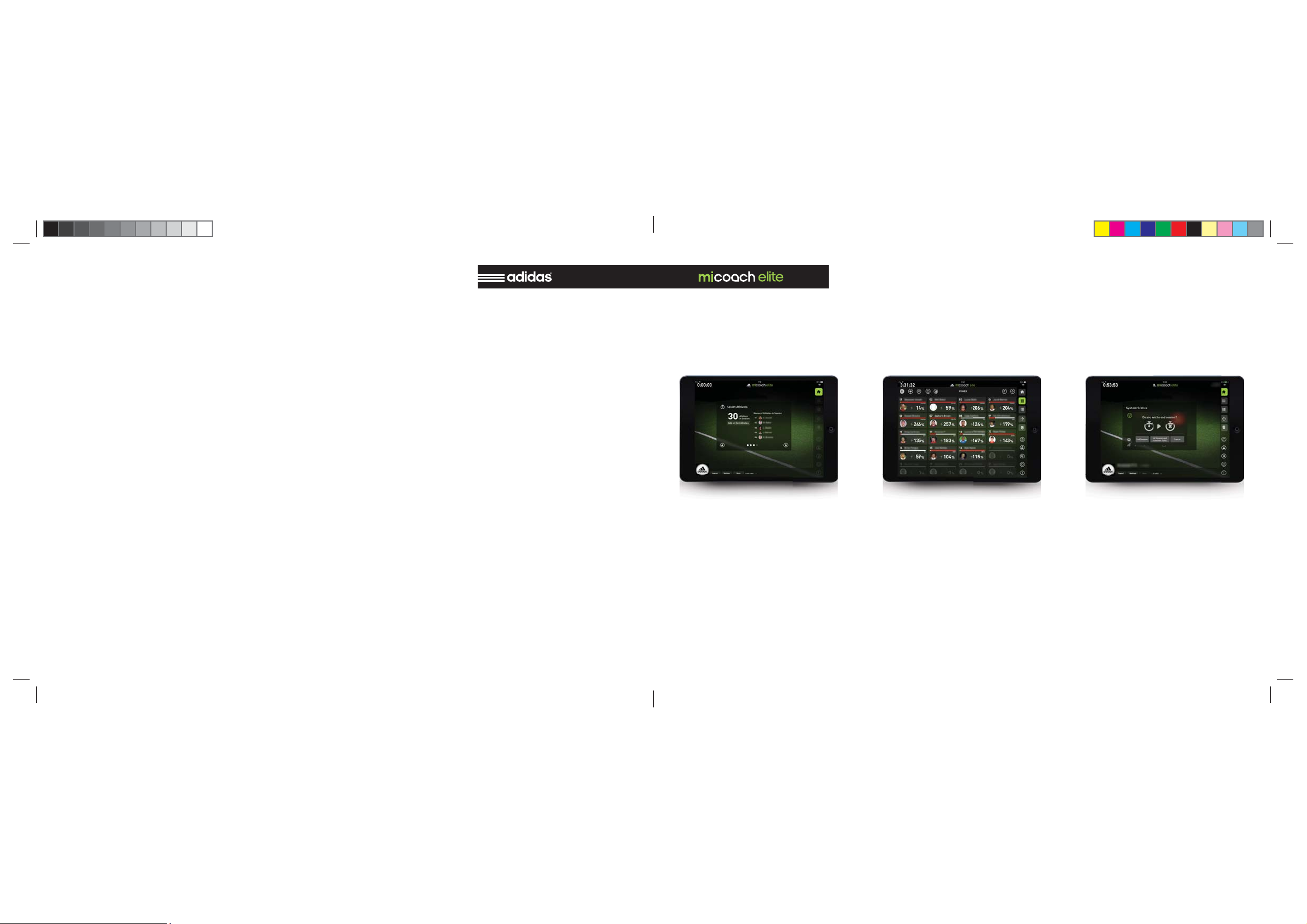
STARTING SESSION
Continue through the start up screens
and start your session. Select “Cells” to
confi rm that the assigned player cells
are correct and live data is streaming.
Select “Drills” to start a drill and begin
associating your data with a drill.
LIVE MONITORING ON THE FIELD
Select “Grid” and “List” to monitor your
live dashboards. Tap any athlete to view
a detailed athlete dashboard.
ENDING A SESSION
When your training session is complete,
stop the session from the “home” page.
Collect Cells and plug them into the
Cells Chargers for charging and uploading.
6 35
Page 7
IPAD APPLICATION
ABOUT THE SYSTEM
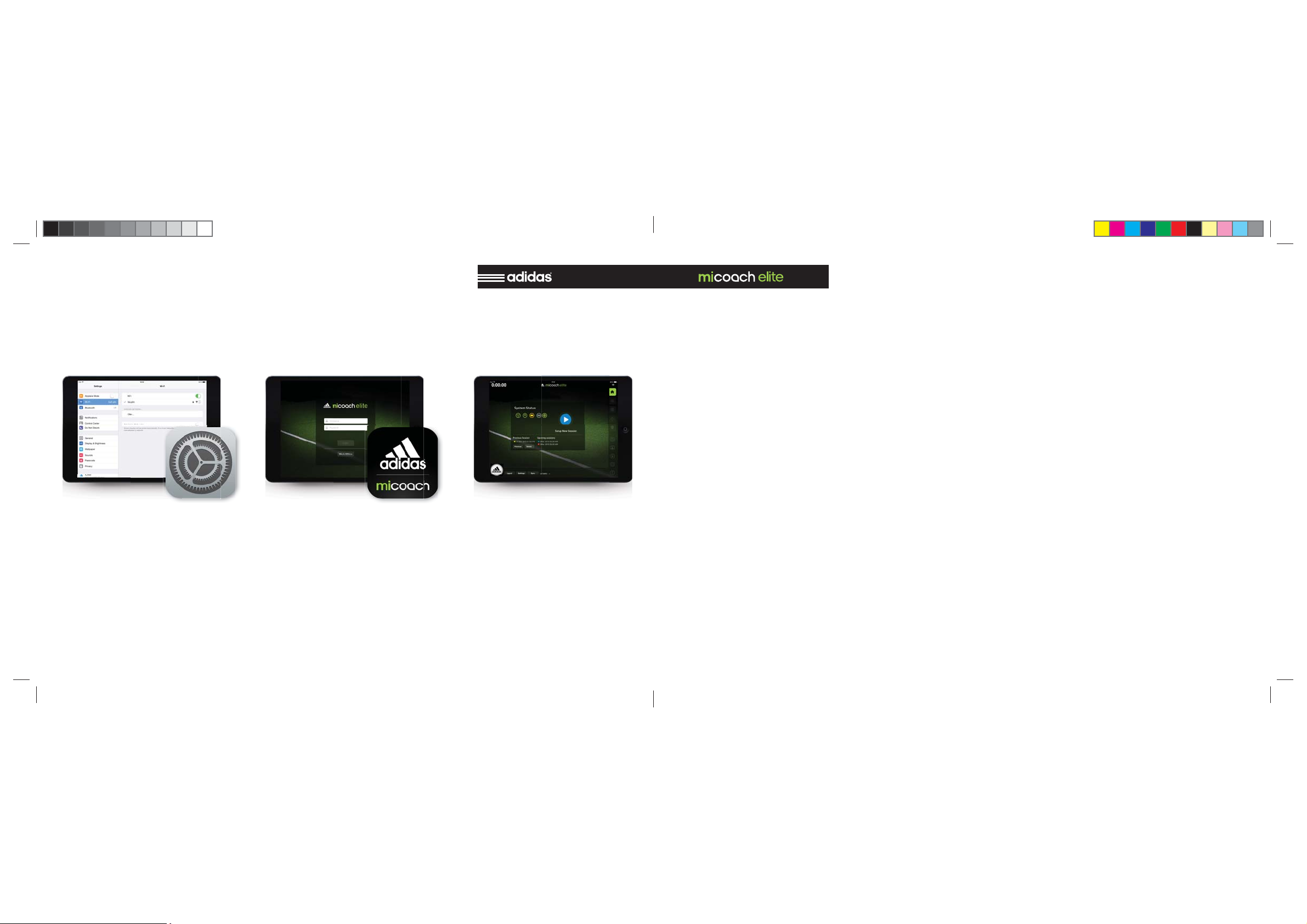
GETTING STARTED ON THE FIELD
CHECK WIFI
Make sure your iPad is connected to the
Base Station WiFi network. Name of the
WiFi starts with “bs2-...”.
LOGGING IN
Log into the app with the user name and
password you created on the miCoach
web site. Each iPad must be signed in
with a different user name.
CHECK THE STATUS
Check the status indicators to make
sure all connections and sensors are
working.
OVERVIEW
miCoach Elite represents the latest advancement in performance monitoring.
The state-of-the-art system gives athletes and teams a powerful, yet easy to
use tool to help them achieve and maintain peak physical performance and gain
an edge on their competition.
Teams can now accurately plan, monitor, analyze and report on the performance of athletes with one integrated
system.
The micoach elite Team System is designed to perform tasks that aid training
and coaching staff, including:
Provide real-time insights during
training
Track total training impact and ben-
efi ts
Simplify the collection and manage-
ment of data
Add fl exibility with a highly portable
system
HOW IT WORKS
miCoach Elite Team system uses state
of the art sensor technologies along with
compact electronics, specialized fabrics/
fi bers and wireless communication to
provide non-invasive monitoring of athletes in real-time.
adidas brings together GPS, inertial
sensors, heart rate monitoring, and
other technologies along with an understanding of elite athletes and their
training and developmental needs. Sophisticated algorithms process millions
of data points to bring simple, actionable
insights.
WHAT IT MEASURES
miCoach elite was designed to take
millions of data points and boil them
down to simple, intelligent feedback for
coaches who want to understand how
training is impacting athletes and their
performance.
34
7
Page 8

ABOUT THE SYSTEM
METRICS
HEART RATE POWER SPEED
During a training session, a coach can
use the live dashboard to monitor heart
rate recovery making sure not to begin
the next training interval until the majority of athletes are ready.
This is a precise measure of how hard
the athlete is working. Power training is
widely used in cycling where it has been
possible to measure with a meter on the
bike. Advanced sensor technology and
algorithms in the miCoach elite team
system will now enable power to be
used in fi eld sports.
By combining power and heart rate,
coaches now have a complete picture of
how hard an athlete is working and how
their body is responding to the work.
This combination of metrics allows
coaches to look at the overall effi ciency
of an athlete. Athletes that are putting
out more work per heart beat are in better condition.
By monitoring speed, a coach can see
if athletes are training at the level that
is required to succeed in a game. When
a coach plans a speed training session,
he can customize the live dashboard to
view speed related data including peak
speed, average speed, and number of
high-intensity sprints. The ability to
manage speed training carefully is essential to prevent over training and risk
of injury.
ENTER YOUR ATHLETES
Create an athlete profi le for each play-
er. Set threshold values for the various
metrics.
CUSTOMIZE YOUR SETTINGS
Select your metric preferences.
CENTRAL WEB SYSTEM
BUILD YOUR SCHEDULE
Add games, practice and rest days. Create training session plans and add drills.
SYNC WITH THE BASE STATION
A base station sync is done by connecting the base station to the web. A confi rmation of the sync can be found at the
top of the web pages.
8
33
Page 9

CENTRAL WEB SYSTEM
ABOUT THE SYSTEM
GETTING STARTED ON THE WEB
PREPARATION
Before using the miCoach system for
a training session, you must perform
multiple steps via the miCoach elite web
app. The app is intuitive and will guide
you through the following steps.
CREATE USER ACCOUNTS
Enter profi les and set up access levels
for users.
DEFINE ZONES AND LOAD WEIGHTS
Enter profi les and set up access levels
for users.
CUSTOMIZE FOR YOUR CLUB
Enter profi les and set up access levels
for users.
METRICS
DISTANCE
The distance an athlete runs during
a game or scrimmage can vary. A real-time measure of distance allows a
coach to set individual or team targets
for distance and ensure that all athletes
meet their goals. During or at the end of
a scrimmage, a coach can use the live
app to check distance covered. Athletes
that fall short of the target will continue
to train.
ACCELERATION / DECELERATION FIELD POSITION
These measures are critical in sports
where rapid change of direction is required. Understanding the rate and
frequency of accelerations and decelerations is an important part of overall
training load.
This allows a coach to see where the
athletes have been on the fi eld giving
insight into tactical movements of the
players.
32
9
Page 10

COMPONENTS OVERVIEW
SHUTTING DOWN BASE
BASE STATION
The Base is a portable receiver that collects
data from up to 30 Cells and can transmit that
data in real-time to the miCoach Elite Dash via
WiFi. Data from three sessions can be stored
locally on the Base.
When connected to the Internet, the Base
uploads data to a team’s secure web server for
post-session analysis and reporting. The Base
also serves as a storage and charging port for
the Cells used with the Team System.
The unit is portable, rugged and
weather-resistant.
HARD RESET
Using of Hard Reset is not recommended,
only when system seems stuck and not
responding to normal operation.
Press the
Reset Button on back of the
Base Station with a long pin.
At fi rst, Power Button will start
blinking yellow.
Reset takes several
minutes.
FORCE SHUTDOWN
Using of Force Shutdown is not recommended,
to use only when the system is stuck.
Press the
Power Button
for 5 seconds.
Base Station will start
shutting down
immediately.
10
31
Page 11

SHUTTING DOWN BASE
COMPONENTS OVERVIEW
NORMAL SHUTDOWN
Normal Shutdown should always be used when you want
to turn off the system.
If shutdown is rejected (Power Button blinks 3 times red),
you might need to wait for the training session to fi nish.
Short Press the
Power Button
,
it will start
blinking yellow.
Shutting down takes
about a minute.
BASE STATION FRONT
PCONE ANTENNA INPUT
For connecting pCone antenna.
PCONE ANTENNA LED
Indicates pCone antenna status.
BASE STATION WIFI LED
Indicates Base Station
WiFi status.
BASE STATION BATTERY LED
Indicates Base Station
battery status.
CELLS CHARGERS LED
Indicates cells chargers
status.
CENTRAL WEB SYSTEM LED
Indicates connection to CWS (Cen-
tral Web System) status.
POWER BUTTON
For turning ON/OFF Base
Station, and status indicator.
30
11
Page 12

COMPONENTS OVERVIEW
BASE STATION LED’S
BASE STATION BACK AND BOTTOM
USB PORTS
For connecting Cells Chargers USB cable.
ETHERNET CABLE PORT
For connecting Ethernet
cable.
POWER SUPPLY INPUT
For connecting Base
Station power adapter.
BACK SIDE
BOTTOM SIDE
RESET BUTTON
Only for the Customer
Support usage.
HDMI PORT
Only for the Customer
Support usage.
HARD POWER BUTTON
For turning off power
completely (e.g. in Flight
Mode when traveling).
CELLS CHARGERS LED
OFF SOLID GREEN SOLID RED
DISCONNECTED
No chargers connected
to the Base Station.
2 CHARGERS
2 charger units connected to
the Base Station.
BLINKING GREEN
1 CHARGER
1 charger unit connected to
the Base Station.
FAST BLINKING GREEN
SYNC IN PROGRESS
Data from Cells is transfered
to the Base Station.
SYNC ERROR
An error occurred while
synchronizing data from Cells.
Contact Customer Support
if this persists.
12
29
Page 13

BASE STATION LED’S
COMPONENTS OVERVIEW
PCONE ANTENNA LED
OFF SOLID GREEN SOLID YELLOW SOLID RED
DISCONNECTED
No pCone antenna attached.
READY
pCone antenna is attached and
ready to start session.
ONGOING SESSION
Session in progress. Data from
Cells is transfered real-time
to the Base Station.
SOFTWARE UPDATE
pCone antenna software
update, please wait
until it’s fi nished.
FAST BLINKING YELLOW BLINKING REDFAST BLINKING GREEN
SOFTWARE UPDATE
pCone antenna software
update, please wait
until it’s fi nished.
INVALID SOFTWARE
Invalid software version on
pCone antenna, please con-
nect Base Station to Internet.
PCONE ERROR
Please reconnect pCone an-
tenna. Please contact Custom-
er Suppor if this persists.
CELLS CHARGERS
CELL CHARGING
INDICATOR
Yellow when
charging, green when
CELL SLOTS
When plugged into
the slots cells are
charging. Also used
to transfer data via
USB cable.
POWER OUTPUT CHARGER IPAD BASE POWER INPUT POWER INDICATOR
For sharing
power with
secondary charger.
For connecting
secondary charger to
transfer Cells data.
For connecting
iPad to charge.
For sending data
from Cells to Base
Station.
For connecting Cells
Chargers power
adapter.
When is green, power adapter is properly
connected.
charged.
28
13
Page 14

COMPONENTS OVERVIEW
BASE STATION LED’S
CELL PCONE
ON / OFF BUTTON PCONE ANTENNA
Long press for ON, and
long press for OFF.
SENSOR CONNECTORS
Connectors to the t-shirt
sensors, clip into
the pocket of the t-shirt.
For communication
with Cells.
EXTRA ROD
For extending the height
of pCone antenna,
for better signal
reception.
BASE STATION WIFI LED
OFF SOLID REDSOLID GREEN
WIFI IS OFF
Base Station WiFi is OFF. You
cannot connect with the iPad
app to the Base Station.
WIFI IS ON
Base Station WiFi is ready to
operate. You can connect to
Base Station with iPad.
Base Station network name
starts with “bs2-...”.
WIFI ERROR
Base Station WiFi
had a problem.
Please contact
Customer Support
if this persists.
14
27
Page 15

BASE STATION LED’S
COMPONENTS OVERVIEW
CENTRAL WEB SYSTEM (CWS) CONNECTION LED
OFF SOLID GREEN BLINKING RED
NO CONNECTION
No connection to CWS, you
cannot synchronize data with
web servers.
READY TO SYNC
Connection with CWS estab-
lished, system is ready to syn-
chronize data with servers.
FAST BLINKING GREEN
SYNC IN PROGRESS
CWS connection active.
Synchronization with web
servers in progress.
26
CONNECTION ERROR
Limited Internet connection,
CWS unreachable. Try to
connect to a different Internet
source, and try again.
Please contact Customer
Support if this persists.
T-SHIRT
CELL POCKET HEART RATE SENSORS
Pocket for a Cell.
Each athlete is outfi tted with a me-
dium compression base layer that
works with the Cell.
Specialized fi bers are integrated into
the base layer to transmit data to the
Cell. The base layer is available in
a range of sizes for optimum fi t and
accurate data collection. The Cell
rests between the shoulder blades
so it does not interfere with training
or game play.
Sensors detect and read
athletes heart rate.
15
Page 16

COMPONENTS OVERVIEW
BASE STATION LED’S
T-SHIRT
SENSOR CONNECTORS
Best way to know what size to put on a player is to measure the circumference of his torso under his pectoral muscles.
If you do not have access to that measurement you can also estimate the
shirt fi t using height and weight. Consult the sizing chart.
FIT
The heart rate sensors on the front of the Techfi t elite smart shirt must lay
fl at on the rib cage and not shift around as the athlete moves. This is most
effectively accomplished when the smart shirt fi ts like a second skin.
Athletes may request a larger shirt but if the sensors do not fi t fl at on the
chest wall, they will not collect data consistently.
It is also important that the Techfi t elite smart shirt be the base layer. The
sensors must make contact with the skin to record heart rate.
STARTUP
Depending on a player unique body chemistry, heart rate may be detected
immediately on the Cell. However, many athletes may need a warm up period before the heart rate can be detected.
Pre wetting the sensors with tap water or electrogel can help reduce the
length of the warm up period signifi cantly.
Do not use more than fi ngertip-sized amount of gel to spread over the sen-
sor. Too much will cause the sensor to slide around and give a poor signal.
16
80 85 90 95 100 105 110
X-Small
32 33 34 35 36 37 38 39 40 41 42 43
230
220
210
200
190
180
170
Weight (Pounds)
160
150
140
130
120
Centimeters
Small
Medium
60 62 64 66 68 70 72 74 76 78 80 82 84
S
60 62 64 66 68 70 72 74 76 78 80 82 84
Large
Inches
Height (inches)
XL
L
M
Height (cm)
X-Large
BASE STATION BATTERY LED
OFF SOLID GREEN
NO CHARGING
Hard switch is on position ‘0’,
105
100
95
90
85
80
Weight (kg)
75
70
65
60
55
to enable power, put the hard
Switch to position “I”.
DRAINING 100% - 50%
Battery is draining, the level
is between 100% - 50%, or
battery is fully charged.
PULSING
BATTERY CHARGING
Battery level is in accordance
with the info above. Base Sta-
tion power adapter
is plugged in.
SOLID YELLOW SOLID RED
DRAINING 50% - 25%
Battery is draining, the level is
between 50% - 25%.
DRAINING 25% - 10%
Battery is draining, the level is
between 25% - 10%.
Battery is draining, the level is
FAST BLINKING RED
Make sure BS is in tempera-
ture between -10
it won’t fi x the problem, please
contact Customer Support.
BLINKING RED
DRAINING 10% - 0
lower than 10%.
CHARGING ERROR
O
C / 40OC., if
25
Page 17

BASE STATION LED’S
COMPONENTS OVERVIEW
POWER BUTTON LED
OFF
SYSTEM IS NOT STARTED
To enable power, put the hard
Switch to position “I”,
and short press Power Button.
BLINKING GREEN
BOOTING UP
Base Station prepares
the system to operate.
SOLID GREEN
BASE STATION ON
Base Station is ready
to operate.
BLINKING YELLOW 3x BLINKS RED
SHUTTING DOWN
Base Station is closing the
system.
ONGOING PROCESS
Rejected shutdown.
You might need to wait for the
training session to fi nish.
If this persists please contact
Customer Support.
T-SHIRT
SHIRT ASSIGNMENT
A specifi c Techfi t elite smart shirt can be assigned to a player or a different shirt can be used in
each session.
This is the kit manager’s choice.There is a writable label at the back inside hem of the shirt to
assign a player to a specifi c smart shirt or identify each garment for tracking purposes.
REMOVING THE SMART SHIRT
Since the Techfi t elite smart shirt fi ts like a second skin, it can be more diffi cult to remove than
a loosely fi tting shirt, especially after a workout.
Do not pull from the neckline. Instead, please try one of these suggestions:
Pull up from the bottom hem of the shirt and remove, twisting the torso and shoulders as needed. Ask another player to pull the shirt over the head while pulling from the back, bottom hem.
CARE INSTRUCTIONS
Remove micoach elite Cell from the pocket on the back of the Techfi t elite smart shirt.
Wipe the micoach elite Cell off with a soft, dry cloth and set aside.
Wash the Techfi t elite smart shirt as soon as possible after use—at least within a few hours.
DO NOT let it sit wet overnight.
Machine wash with warm water, laundry detergent and hang dry.
Do not bleach, iron the harness area or tumble dry .
Air dry completely before packing in a bag.
24
17
Page 18

CONNECTING COMPONENTS
INSERT CELL INTO T-SHIRT
INSERT CELL INTO POCKET
Insert Cell into pocket on the
back of the t-shirt.
CLICK THE BUTTONS
Close the Cell in the pocket by
pressing the pins.
BASE
STATION
STEPS
IPAD
STEPS
STARTING NEW SESSION
STEP 1 STEP 2 STEP 3 STEP 4
Connect all com-
ponents as on the
“Connecting
Components”
tutorial.
Connect iPad
to the Base Station
WiFi. Name of the
Base Station WiFi
Set the
Hard Switch Button
on bottom
of Base Station
to position “ I “
STEP 5 STEP 6
Launch
miCoach Elite
application
starts with:
“bs2-...”
THAT’S ALL
You are ready to
launch your fi rst
training session.
Short press
“Power Button” on
the Base Station
STEP 7
Follow
the instructions
on iPad application.
Wait until
WiFi LED is
Solid Green.
18
23
Page 19

CONNECTING COMPONENTS
CONNECTING COMPONENTS
ASSEMBLING PCONE ANTENNA AND CONNECTING TO BASE STATION
RED DOT TO RED DOT SCREW THE LID
Connect pieces in place
of dots (antenna on
top).
Put the lid down and turn
it till you feel resistance.
INSERT CELL INTO CHARGER
PINS TO GAPS
Put the Cell into Charger, so
that the pins on Cells fi t to
gaps on Cells Charger. Press
the Cell into Cell Charger
until you feel the Click.
CONNECTION INDICATOR
If Cell is properly connected,
the light should appear. Green,
when Cell is fully charged, amber, when Cell is charging.
22
19
Page 20

CONNECTING COMPONENTS
CONNECTING COMPONENTS
CONNECTING CELL CHARGERS TOGETHER
POWER SOURCE
Connect OUT slot with IN slot
in the second Charger, using
the provided cable. For sharing
power.
DATA TRANSFER
Connect CHARGER slot with
BASE slot in the second Charger, using the provided cable.
Serialize USB connection.
CONNECTING CHARGERS TO BASE STATION
SYNCING DATA
Connect BASE slot in Cells
Charger with the USB slot on
Base Station with the provided
cable.
20
21
Page 21

Specifications
Base Station
Charger
Player_Cell
Power
Input 19Vdc (+20%, -15%) 5A max
Input 19Vdc (+20%, -15%) 5A max
Input 5Vdc(+/- 5%) 0.5A max
7.2V 8.4Ah 126Wh Lithium Ion
Rechargeable Battery
3.7Vdc 0.8Ah 3.0Wh Lithium Ion
Rechargeable Battery
RF Protocol
IEEE 802.15.4
IEEE 802.15.4
Frequency (MHz)
2400
2400
Technology
ZigBee®
ZigBee®
Wireless
IEEE 802.11 a / b / g / n
Bands
Dual Band 2.4GHz / 5GHz
Operating Frequency Range (MHz)
2402 - 2472
5170 - 5710 *
Security
64 / 128 - bits WEP, WPA, WPA2, 802.1x
Operating Temperature Range
0 °C to 40 °C
0 °C to 40 °C
0 °C to 40 °C
Input Power Requirements
AC Input 100 - 240Vac 50 / 60Hz 1.5A
AC Input 100 - 240Vac 50 / 60Hz 1.5A
DC Output 19.5Vdc 4.47A
19.5Vdc 4.47A
Note: * Some Frequency Channels will be closed due to individual country
regulations
1
 Loading...