


 Loading...
GTP-870HD Preamp/Processor
User’s Manual
G |
T P - 8 |
7 |
0 |
H |
D |
|
standby |
|
|
|
|
roomtwo |
|
on/off |
setup |
FM/AM
tune/preset
video1
video2 |
video3 |
video4
tape
CD
ext7.1
up
down
surmode
volume
|
• The latest version of the firmware is |
|
required to enable all functionality |
STOP |
described in this manual. |
• Check the Adcom website |
|
|
(www.adcom.com) for firmware |
|
updates. |
Congratulations on your purchase of the Adcom GTP-870HD
You have made a wise choice that will reward you with exceptionally accurate musical sound reproduction for years to come. To realize the full potential of your new preamp/processor, please read these operating and installation instructions thoroughly before attempting to make any connections to it.
The GTP-870HD is not only designed to reproduce the highest quality sound and picture but also to deliver the greatest possible value. It is our engineers’ passion for perfection that has enabled our components to be judged the equivalent of others costing two, three, or even five times as much. Our engineering team consistently strives to develop and design products that will exceed your expectations. Our goal at Adcom is to let more consumers hear high-end quality sound and see high-end video without paying high-end prices.
All Adcom components are the result of a long-standing dedication to innovation, quality, simplicity, and value. Adcom: We have the power — and now, so do you!
This symbol is intended to alert the user to the presence of uninsulated dangerous voltage within the product’s enclosure that may be of sufficient magnitude to constitute risk of fire or electric shock.
This symbol is intended to alert the user to the presence of important operating and maintenance instructions in the literature accompanying this product.
Do not place this unit on an unstable cart, stand, tripod, bracket, or table. The unit may fall, causing serious injury to a child or adult, and serious damage to the unit. Use only with a cart, stand, tripod, bracket, or table recommended by the manufacturer or sold with the unit. Any mounting of the device should follow the manufacturer’s instructions, and should use a mounting accessory recommended by the manufacturer.
Copyrights/Trademarks
Published by Adcom
Copyright © 2006 Adcom, LLC
All rights reserved
Adcom and the Adcom logo are registered trademarks of Adcom, LLC.
This unit is manufactured under license from Dolby Laboratories Licensing Corporation. It is additionally licensed under one or more of the following patents: U.S. number 3,959,GTP880, Canadian numbers 1,004,603 and 1,037,877.
Dolby® Pro Logic®, Dolby ProLogic II®, Dolby Digital EX®, and Dolby Digital® are registered trademarks of Dolby Laboratories Licensing Corporation.
Manufactured under license from Digital Theater Systems, Inc. US Patent Number 5,451,942 and other world-wide patents issued and pending. “DTS®,” “dts®,” “DTS Digital Surround®,” “DTS-ES®,” “DTS NEO:6®” are trademarks of Digital Theater Systems, Inc. Copyright 2003 Digital Theater Systems, Inc. All rights reserved.
HDMI, the HDMI logo and High-Definition Multimedia Interface are trademarks or registered trademarks of HDMI Licensing LLC.
No part of this manual may be reproduced or electronically transmitted without the express written consent of Adcom, LLC.

Chapter 1 - Welcome
Introduction ………………………………………………… 5 Key Features………………………………………………… 5 Unpacking the GTP-870HD ………………………… 5 Placing the GTP-870HD ……………………………… 6 About the Remote Control ………………………… 6 Front Panel Overview ………………………………… 7 Remote Control Overview…………………………… 8 Rear Panel Overview……………………………………10
Display Overview …………………………………………12
Chapter 2 - Connections
Connections Overview …………………………………13
Before You Begin …………………………………………13
AM/FM Antenna Connections ………………………14
Basic Audio/Video Connections …………………15
DVD Player Connections ………………………………16
Component/Progressive Scan Connections …17 Digital Audio Connections ……………………………18
HDMI Connections ………………………………………19
External Decoder Connections ……………………20
CD/Tape Player Connections ………………………21
TV/Monitor Connections…………………………… 22 Speaker Placement…………………………………… 23 Amplifier Connections (XLR) ………………………24
Amplifier/Subwoofer Connections (RCA) … 25 Video Recorder Connections ………………………26
Tape Out/Aux Connections …………………………27
Room 2 Connections ………………………………… 28 Control Connections ……………………………………29
Power Connections …………………………………… 30
Chapter 3 - Setup
Setup Overview……………………………………………31
Setup Navigation …………………………………………32
Input Configuration………………………………………33
HD Scaler Configuration …………………………… 34 Picture Controls……………………………………………35
Volume/Tone Configuration……………………… 36 Speaker Configuration …………………………………37
Delay Configuration ………………………………… 38 Channel Balance …………………………………………39
Pro Logic IIx/Neo:6 Configuration …………… 40 Room 2 Basic Configuration …………………………41
Room 2 Advanced Configuration …………………42
System Configuration……………………………………43
Input Labeling…………………………………………… 44 Analog Input Level …………………………………… 45 Remote Control Setup ……………………………… 46 Using Preprogrammed Commands ………………47
Programming Remote Commands …………… 50 Deleting Remote Commands ………………………51
Programming Macro Buttons ………………………52
Discrete Remote Control Commands …………53
Chapter 4 - Operations
Operations Overview……………………………………55
Basic Audio/Video Playback……………………… 56 Picture Format ………………………………………… 56 External 7.1 Playback ……………………………… 56 Tape Playback…………………………………………… 56 Selecting Surround Modes……………………………57
Tone Control……………………………………………… 58 Basic Recording ……………………………………………59
Tuner Operations ……………………………………… 60 System Operations ………………………………………61
Room 2 Operations ………………………………………62
Chapter 5 - Help
Customer Support ………………………………………63
Adcom Protection Plan ………………………………63
Product Care & Maintenance ………………………63
System Reset ………………………………………………63
Troubleshooting………………………………………… 64 Technical Specifications ………………………………65
Index ………………………………………………………… 66
Contents of Table
www.adcom.com |
GTP-870HD Owner’s Manual |
3 |
Important Safety Instructions
Important Safety Instructions
•Read all the safety and operating instructions before connecting or using this unit.
•Retain this notice and the owner’s manual for future reference.
•All warnings on the unit and in its operating instructions should be adhered to.
•All operating and use instructions should be followed.
•Do not use this unit near water. For example, near a bathtub, washbowl, kitchen sink, laundry tub, in a wet basement, or near a swimming pool.
•The unit should be installed so that its location or position does not interfere with its proper ventilation. For example, it should not be situated on a bed, sofa, rug, or similar surface that may block the ventilation openings; or placed in a built-in installation, such as bookcase or cabinet, that may impede the flow of air through its ventilation openings.
•The unit should be situated away from heat sources such as radiators, heat registers, stoves, or other devices (including amplifiers) that produce heat.
•The unit should be connected to a power supply outlet only of the voltage and frequency marked on its rear panel.
•This Class I apparatus shall be connected to a MAINS socket outlet with a protective earthing connection.
•As the plug is used as the disconnect device, the disconnect device shall remain readily operable.
•The power supply cord should be routed so that it is not likely to be walked on or pinched, especially near the plug, convenience receptacles, or where the cord exits from the unit.
•Clean unit only as recommended in its instruction manual.
•The power supply cord of the unit should be unplugged from the wall outlet when it is to be unused for a long period of time and during electrical storms.
•Care should be taken so that objects do not fall, and liquids are not spilled, into the enclosure through any openings.
•This unit should be serviced by qualified service personnel when:
a.The power cord or the plug has been damaged; or
b.Objects have fallen, or liquid has been spilled, into the unit; or
c.The unit has been exposed to rain, or liquids of any kind; or
d.The unit does not appear to operate normally, or exhibits a marked change in performance; or
e.The device has been dropped, or the enclosure damaged.
Regulatory Information
FCC Part 15 This product has been tested and found to comply with the limits for a Class B digital device,
of the FCC Rules. These limits are designed
able protection against harmful interference when the
is operated in a residential installation. This product generates, uses, and can radiate radio frequency energy and, if not installed and used in accordance with the instruction
harmful interference to radio communications
no guarantee that interference will not occur in a particular installation. If this product does cause harmful interference to radio or television reception, which can be determined by turning the product off and on, the user is encouraged to try to correct
the interference by one or more of the following measures:
•Reorient or relocate the receiving antenna.
•Increase the separation between the product and receiver.
•Connect the product into an outlet on a circuit different from that to which the receiver is connected.
•Consult the dealer or an experienced radio/TV technician for help.
WARNING
TO REDUCE THE RISK OF FIRE OR ELECTRIC SHOCK, DO NOT EXPOSE THIS UNIT TO RAIN OR MOISTURE.
CAUTION
TO PREVENT ELECTRIC SHOCK DO NOT USE THIS POLARIZED PLUG WITH AN EXTENSION CORD, RECEPTACLE OR OTHER OUTLET UNLESS THE BLADES CAN BE FULLY INSERTED TO PREVENT BLADE EXPOSURE.
THERE ARE NO USER SERVICEABLE PARTS IN THIS PRODUCT. DO NOT ATTEMPT SERVICING OF THIS UNIT YOURSELF. REFER SERVICING TO QUALIFIED SERVICE PERSONNEL.
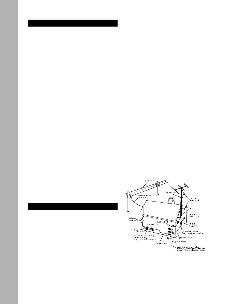
CAUTION POWER LINES
Any outdoor antenna must be located away from all power lines.
OUTDOOR ANTENNA GROUNDING
If an outside antenna is connected to your tuner or tuner/preamplifier, be sure the antenna system is grounded so as to provide some protection against voltage surges and built-up static charges. Section 810 of the National Electrical Code, ANSI/NFPA No. 701984, provides information with respect to proper grounding of the mast and supporting structure, grounding of the lead-in wire to an antenna discharge unit, size of grounding conductors, location of antenna discharge unit, connection to grounding electrodes, and requirements for the grounding electrode.
a.Use No.10 AWG (5.3 mm2) copper, No.8 AWG (8.4 mm2) aluminum, No.17 AWG (1.0 mm2) copper clad steel or bronze wire, or larger, as a ground wire.
b.Secure antenna lead-in and ground wires to house with stand-
|
off |
spaced from 46 feet (1.221.83 m) apart. |
|
c. |
Mount |
|
unit as close as possible to where |
|
lead-in enters |
|
. |
d. |
Use |
not |
than No.6 AWG (13.3 mm2) cop- |
|
per, |
|
antenna grounding |
|
. See |
810-21 |
|
EXAMPLE |
GROUNDING AS PER |
ELEC- |
|
TRICAL |
|
IN ARTICLE 810. RA- |
|
DIO AND |
|
|
|
|
at- |
|
pro- |
vides |
|
that |
|
of the |
. |
4GTP-870HD Owner’s Manual
Chapter 1 - Welcome
Introduction
Introducing Adcom’s new take on the Preamp/Processor: the no-nonsense GTP-870HD.
Who hasn’t grown weary of manufacturers claiming every product on offer as redefining some elusive “standards” or idealizing the ever popular catch-all, “state of the art?” Well, so have we.
So instead of assaulting you with yet another slew of marketing buzzwords and hyperbolic claims, we’ll just proudly introduce to you Adcom’s latest no-non- sense product: The GTP-870HD Preamp/Processor.
Intended to satisfy your requirements for a convenient, uncomplicated home entertainment solution, here’s a single-chassis package of Adcom separatesperformance pedigree, with plenty of power and the stability into low impedance loads to drive any loudspeaker encountered.
Offering a comprehensive list of useful features and digital signal processing modes, the GTP-870HD forgoes costly cosmetic flourishes in exchange for a long-lasting high level of overall build quality, with changeable internal circuit-card construction and functioning serial port communication for future u dates and upgrades.
No hype, no nonsense. Just superior performance and lasting value for your money. What you’ve come to expect from Adcom.
Key Features
•HDMI™ video switcher routes all HDMI and upconverted legacy sources (composite, S-video, and component video) through a single HDMI cable
•Built in Video DSP converts standard NTSC 480i and PAL 576i signals to the output resolution of your display device (up to 1080p)
•Dolby Digital EX, DTS ES and Pro Logic IIx
•Upgradable: Hardware and software-addressable for accommodation of future advancements
•Low voltage protection minimizes effects of power line dips
•Flexible bass management & system calibration
•Independent Room 2 Out with advanced equalization
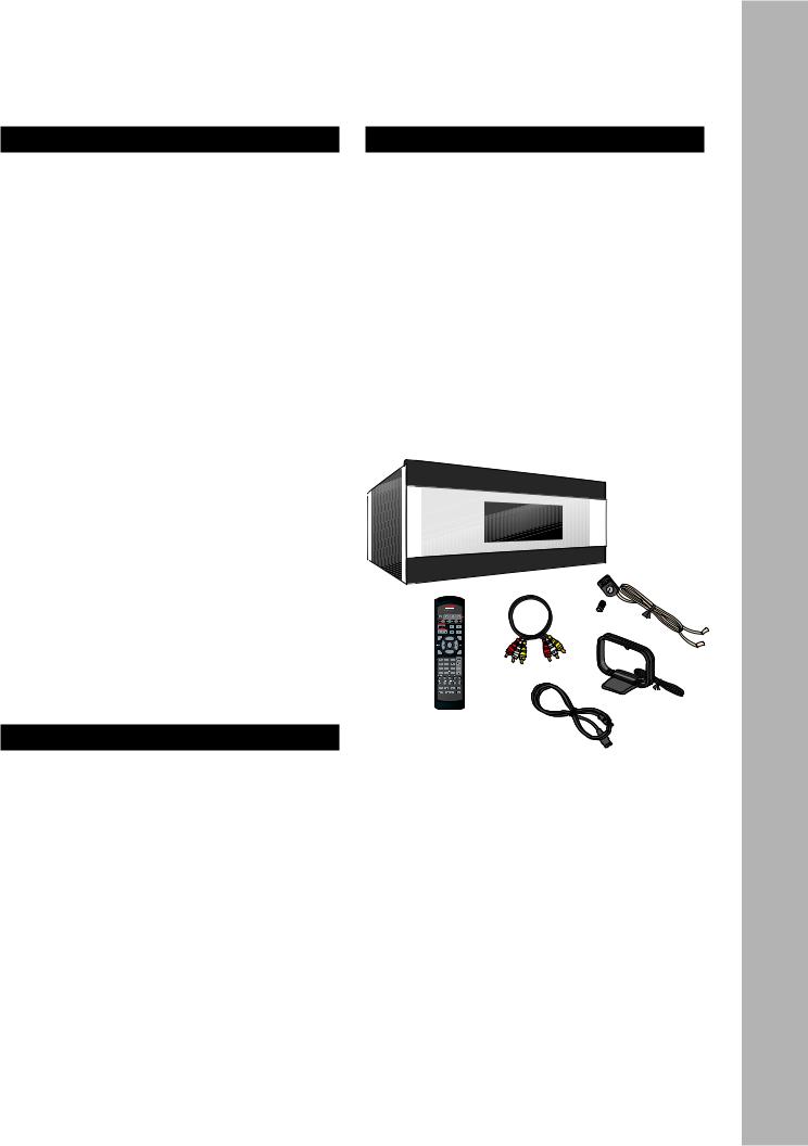
Unpacking the GTP-870HD
Before you begin, please take a moment to make sure the following items were included with your GTP-870HD:
•GTP-870HD
•Remote control
•1.5V AAA batteries (4)
•Audio/video cable
•FM antenna
•FM antenna adapter
•AM loop antenna
•Power cord
•Warranty card & statement
•Quick Reference Guide
•User’s guide CD
Welcome - 1 Chapter
www.adcom.com |
GTP-870HD Owner’s Manual |
5 |
Chapter 1 - Welcome
Placing the GTP-870HD |
About the Remote Control |
Place the GTP-870HD on a stable, vibration-free surface away from moisture and out of direct sunlight. Your Adcom dealer will be pleased to show you many different types of audio/video equipment racks and cabinets.
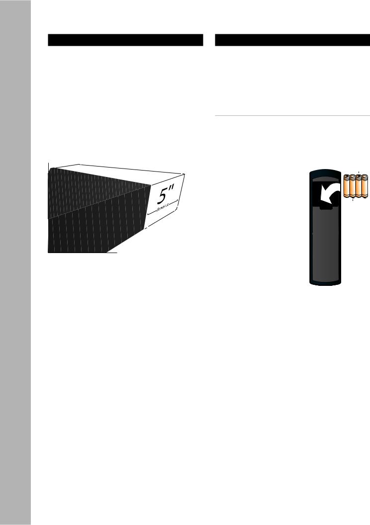
The GTP-870HD’s rear panel is the central connecting point for almost every component in your audio/ video system. Be sure to leave sufficient room behind the rear panel to accommodate cables, antenna leads, power cords, etc. We recommend a minimum of 5 inches of free space for maximum flexibility.
A distance of 1/2” should be maintained around the GTP-870HD for ventilation. Keep your GTP-870HD in a room where temperatures remain fairly moderate, and never cover it with table cloths, curtains, newspapers, etc., to avoid potential overheating.
The GTP-870HD comes with a universal, programmable, backlit, ergonomic remote control that is ready for action in every sense of the word.
•For an overview of each remote button, see page 8.
•To program the remote, see page 46.
Inserting the Remote Batteries
1Remove the cover on the back panel of the remote control.
2Insert four AAA alkaline batteries, paying attention to the correct polarities.
3Replace the cover.
6GTP-870HD Owner’s Manual
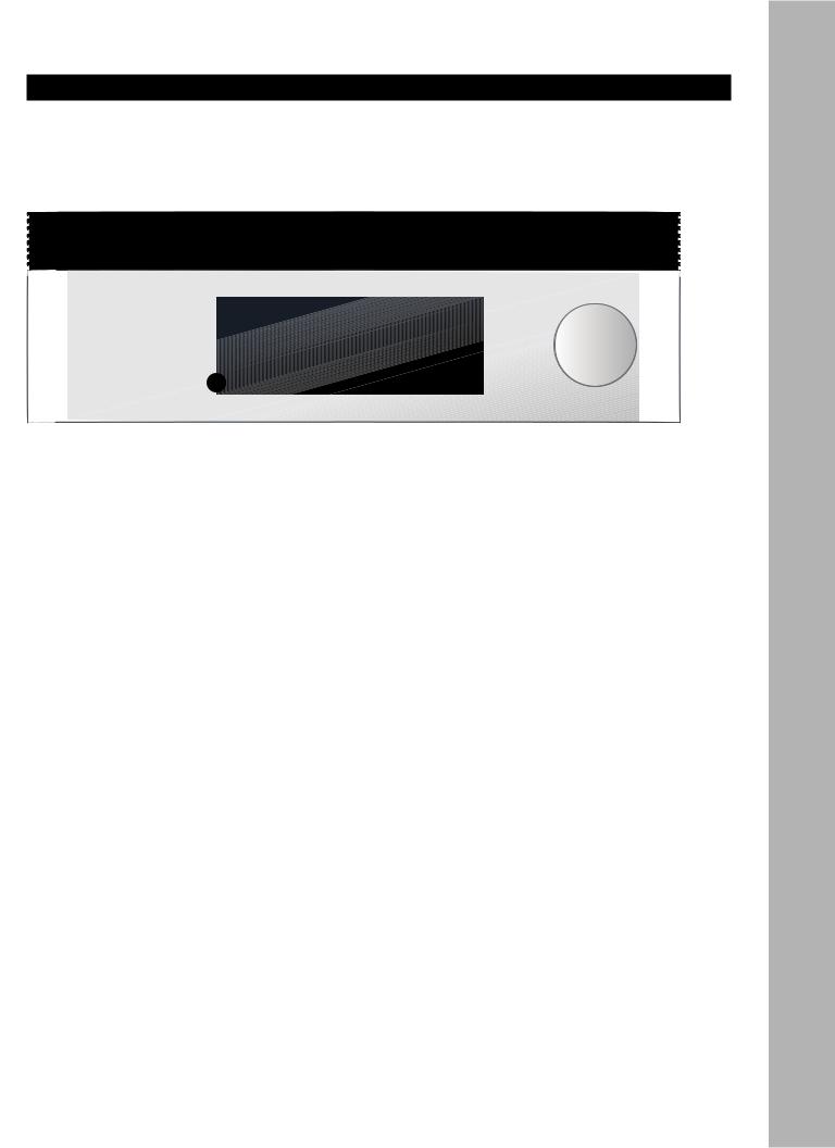
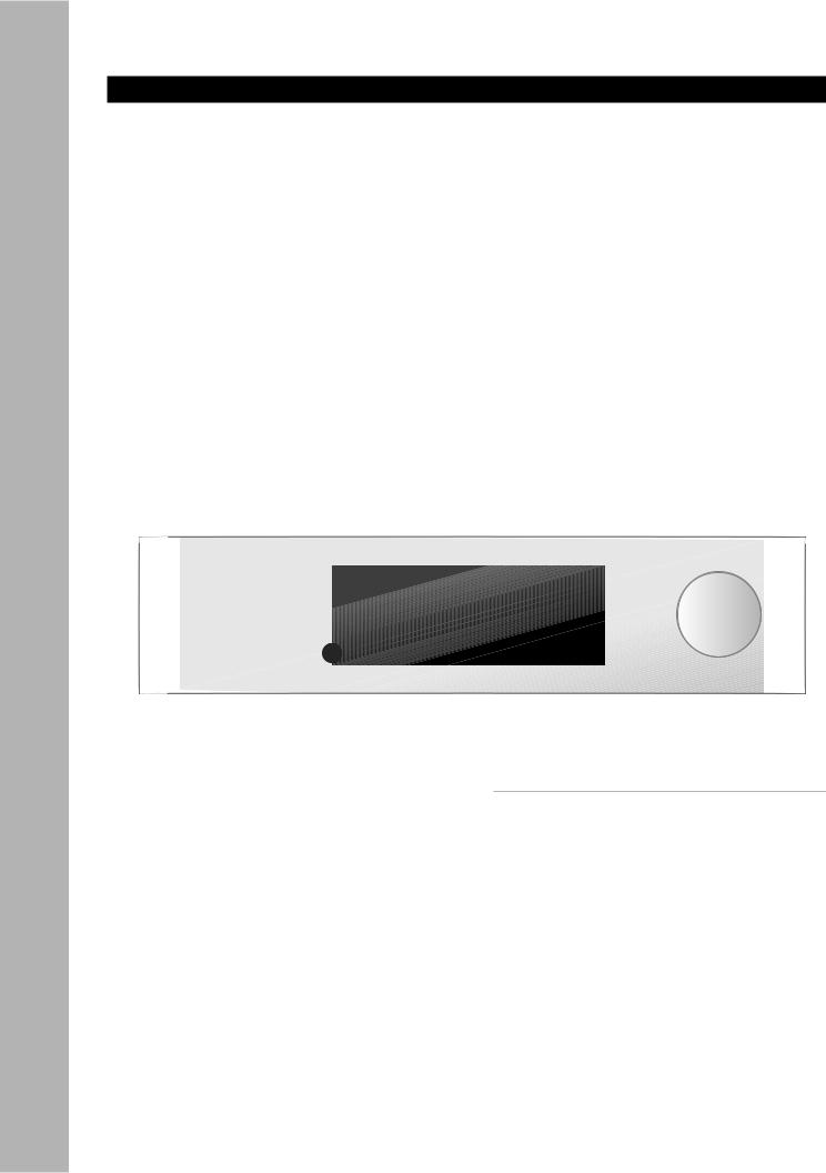
Front Panel Overview
The following is an overview of the GTP-870HD front panel.
1 |
Standby button |
7 |
Ext 7.1 button |
|
|
Powers the GTP-870HD on/off (Standby mode). |
|
Selects the Ext 7.1 inputs, usually connected to |
|
|
• The rear panel power switch must be on |
|
a DVD, DVD-Audio, or SACD player. |
|
|
(1) for this button to function. |
8 |
Surr Mode button |
|
|
• The Power LED glows amber in Standby |
|
||
|
mode and red in On mode. |
|
Steps through all available surround modes |
|
2 |
Room Two On/Off button |
|
(e.g., Dolby Digital, DTS, etc.) for the selected |
|
|
input. |
|
||
|
Activates the GTP-870HD’s Zone 2 outputs, |
|
• Your selection will override the default |
|
|
usually connected to an amplifier/receiver in a |
|
surround mode for the input. |
|
|
second room. |
9 |
FM/AM button |
|
3 |
Room Two Setup button |
|
||
|
Selects Tuner mode. Press repeatedly to switch |
|
||
|
Displays the Zone 2 configuration menu. |
|
between the FM and AM tuner bands. |
|
|
• Press repeatedly to step through the Room |
10 |
Tune/Preset button |
|
|
2 menu options and use the Volume knob |
|
||
|
to make selections. |
|
In Tuner mode, switches between manual and |
|
4 |
Video 1~4 buttons |
|
preset tuning. |
|
11 |
Front panel display |
|
||
|
Selects the Video 1~4 inputs. |
|
||
|
• Selecting an input activates its audio, vid- |
|
Displays GTP-870HD menus and status informa- |
|
|
eo, and configuration settings. |
|
tion (see page 12). |
|
5 |
Tape button |
12 |
Up/Down buttons |
|
|
Monitors the Tape output, usually connected to |
|
In Tuner mode, selects stored presets or manu- |
|
|
a recording device (e.g., a VCR or tape deck). |
|
ally scans the selected tuner band. |
|
6 |
CD button |
13 |
Volume knob |
|
|
Selects the CD input, usually connected to a |
|
Adjusts the volume level for the selected input. |
|
|
CD player. |
|
|
|
www.adcom.com |
|
GTP-870HD Owner’s Manual |
7 |
|
Welcome - 1 Chapter
Chapter 1 - Welcome
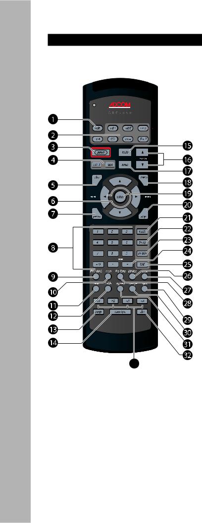
Remote Control Overview
The following is an overview of the GTP-870HD remote control buttons and their operations.
Note: The  remote that can be “taught” to control virtually any component in your home theater system. To program the remote for each input source, see page 46.
1Main button
Selects the GTP-870HD itself, and sets the remote control to the command set associated with the main unit (see page 47).
•In Main mode, pressing any button on the remote control will cause the Main button to glow indicating that the GTP-870HD is active.
2Source Selector buttons
•Vid 1~4 - Selects the Video 1, Video 2, Video 3, or Video 4 input, including the video, audio, and configuration settings associated with that input. Also sets the remote control to the command set associated with that input (see page 47).
•CD - Selects the CD input, including all configuration settings associated with that input. Also sets the remote control to the CD command set (see page 48).
•Tuner - Selects the Tuner input, including all configuration settings associated with that input. Also sets the remote control to the Tuner command set (see page 49).
•Rm 2 - Selects the zone 2 outputs, including all configuration settings associated with that output. Also sets the remote control to the Room 2 command set (see page 49).
3Power button
Powers the GTP-870HD on and off (Standby).
•The rear panel power switch must be on (1) for this button to function.
4Input Select buttons
•Ext7.1 - Selects the Ext 7.1 inputs, usually connected to a DVD, DVD-Audio, or SACD player.
•Tape - Monitors the Tape output, usually connected to a recording device (e.g., a VCR or tape deck).
5Play button
Programmable button. Can be taught to start playback of the selected source component.
6Arrow buttons
Use to navigate the front panel display and onscreen menus.
7Pause button
Programmable button. Can be taught to pause playback of the selected source component.
80-9, 10+ buttons
Programmable buttons. Can be taught to make direct selections (e.g., of DVD chapters or CD tracks) for the selected source component.
9FM/AM/HD button
In Tuner mode, switches between the FM and AM tuner bands.
10Mem button
In Tuner mode, stores the selected station as a preset.
8GTP-870HD Owner’s Manual

11Bass button
When Tone Control is on (by pressing the Bypass button), displays a Bass adjustment display. Use / to set the desired Bass level.
12Treble button
When Tone Control is on (by pressing the Bypass button), displays a Treble adjustment display. Use / to set the desired Treble level.
13Sleep button
Sets the sleep timer to power the GTP-870HD off after a specified length of time (30~180 minutes).
14Backlight button
Turns the remote control backlight on.
•The backlight times out after ~8 seconds.
15Mute button
Mutes the audio for the selected input.
16Volume / buttons
Adjust the volume level for the selected input from -80 dB to +18 dB.
17Setup button
Displays the GTP-870HD Setup menu on the front panel and on-screen displays.
18Menu button
Programmable button. In Main mode, displays the Setup menu. Can be taught to display the Disc Menu on your DVD player.
19Select button
Displays the Picture Format menu. Use / to select a preset format (Auto, Full, Zoom, Squeeze, or Non Linear Stretch) to suit your display device and source material.
•Also use the Select button to make selections in setup menus and on-screen displays.
20Stop button
Programmable button. Can be taught to stop playback of the selected source component.
21Mode button
Steps through all available surround modes (e.g., Dolby Digital, DTS, etc.) for the selected input.
•The Mode button overrides the preset surround mode for the selected input.
22TH-EQ button
Turns Theater EQ sound on and off.
23Ch-Trim button
Displays the Channel Balance menu, which allows you to make custom adjustments to individual speaker levels during playback. A test tone option is provided.
24Tune -/+ buttons
In Tuner mode, manually scans the selected tuner band, or selects stored presets.
25Test button
Plays a test tone for a few seconds in each speaker to aid in setting channel balance.
26St/Mon button
In Tuner mode, switches between Stereo and Mono reception.
•Choosing Mono may improve reception of a poor quality FM station.
27Seek button
In Tuner mode, scans the selected band and automatically tunes in stations with strong signals.
28Preset/Tune button
In Tuner mode, switches between manual and preset tuning.
29Sync button
Displays the Lip Sync Delay menu. If the picture and soundtrack are out of sync, use / to delay the audio signal from 0-169mS.
•While the Lip Sync Delay menu is displayed, press the Sync button again to toggle lip sync delay on and off.
30Dynamic Range button
Adjusts the dynamic range; i.e., the difference between the loudest and quietest passages in an audio soundtrack.
•The default setting is 100% (maximum range).
31Bypass button
Toggles Tone Control on and off. When Tone Control is on, use the Bass and Treble buttons to manually adjust the tone.
32Dim button
Steps through three brightness level for the front panel display.
33Macro buttons (1~4)
Programmable buttons. Can be taught to store and execute up to ten button presses; see page 52.
www.adcom.com |
GTP-870HD Owner’s Manual |
9 |
Welcome - 1 Chapter

Chapter 1 - Welcome
Rear Panel Overview
The following is an overview of the GTP-870HD rear panel.
|
|
|
|
|
|
|
|
|
|
|
|
|
|
|
|
|
|
|
|
|
|
|
|
|
|
|
|

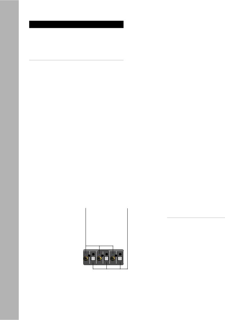
1Tuner inputs
•AM - Connects to an AM loop antenna (included).
•FM - Connects to an FM antenna (included).
2Zone 2 outputs
•Variable (R/L) - Connects to the line inputs of a power amplifier in a second room. With this connection, use the GTP-870HD remote to adjust the volume.
•Fixed (R/L) - Connects to the line inputs of an audio receiver in a second room. With this connection, use the secondary receiver’s controls to adjust the volume.
•12V DC trigger - Use to power on the secondary amplifier/receiver when the Room 2 button is pressed.
3Tape inputs/outputs
•In (R/L) - Connects to the line outputs of a tape player or other analog audio source component.
•Out (R/L) - Connects to the line inputs of a tape recorder or other analog audio recording component. Press the Tape button on the remote control or front panel to monitor the tape output.
4CD inputs (R/L)
Connects to the line outputs of a CD player or other analog audio source component.
5Ext 7.1 inputs
Connects to the multi-channel analog outputs of a DVD, DVD-Audio, or SACD player.
10 |
GTP-870HD Owner’s Manual |
6Analog audio inputs/outputs
•Audio 1~4 inputs (R/L) - Connects to the line outputs of up to four analog audio source components.
•Audio 3~4 outputs (R/L) - Connects to the line inputs of up to two analog audio recording components.
•Aux output (R/L) - Connects to the line inputs of an analog audio component.
7Composite/S-video inputs/outputs
•Video 1~4 inputs (CVBS/S-video) - Connects to the Composite/S-video outputs of up to four video source components.
•Video tape output (CVBS/S-video) - Connects to the Composite/S-video inputs of a video recording component.
8Monitor outputs/HD bypass transcoder
•Video out (CVBS/S-video) - Connects to the Composite/S-video inputs of a TV, monitor, or other display device.
•Video out (Y/Pb/Pr) - Connects to the Component/Progressive Scan inputs of a TV, monitor, or other display device.
9HDMI switcher/scaler
•Video 1~2 in - Connects to the HDMI outputs of an HDMI-compatible source component, such as a DVD player, cable box, satellite receiver, etc.
•Monitor output - Connects to the HDMI inputs of an HDMI-compatible display device.
10Zone 2 IR input
Connects to an IR remote sensor to control the GTP-870HD from Room 2.
11RS232 control
Use to control the GTP-870HD with a PC or home automation system or to upgrade the receiver’s firmware.
12Main controls
•Main IR input - Use to connect a remote IR sensor to control the GTP-870HD if the front panel display is obstructed (e.g., behind closed doors).
•Main 12V DC trigger - Used to power on a compatible component (e.g., an amplifier/receiver or motorized screen) when the GTP-870HD is turned on. This trigger is programmable and can be associated with a specific device.
13Digital audio inputs
•Coaxial 1~3 (75 ohm) - Connects to the coaxial digital audio outputs of up to three digital audio source components.
•Optical 1~3 - Connects to the optical digital audio outputs of up to three digital audio source components.
14Voltage switch
Sets the GTP-870HD voltage to 120V (U.S. standard) or 230 V (international standard).
15Main power switch
Switches the GTP-870HD’s main power on (1) or off (0).
16AC input
Connects the GTP-870HD to a standard electrical outlet using the supplied power cord.
17Balanced audio outputs
Connects to the balanced audio inputs of a power amplifier using XLR cables to feed up to seven speakers (RF/RS/RB/C/LB/LS/LF).
18Component Video inputs
•Video 1~4 (Y/Pb/Pr) - Connects to the Component/Progressive Scan outputs of up to four video source components.
19Subwoofer output
Connects to a powered subwoofer for all speaker configurations.
207.1 Preamp outputs
Connects to the 7.1-channel inputs of a power amplifier.
Welcome - 1 Chapter
www.adcom.com |
GTP-870HD Owner’s Manual |
11 |
Chapter 1 - Welcome
Display Overview
The following is an overview of the GTP-870HD on-screen and front panel displays.
VIDEO 1 |
DOLBY D |
COAXIAL 1 |
-40.0 dB |
On-Screen Display
Front Panel Display
1Video source
Displays the selected video source.
2Audio source
Displays the selected audio source.
•In Tuner mode, displays the selected tuner frequency.
3Surround mode
Displays the selected Surround mode.
•To step through Surround modes, press the Sur Mode button on the front panel or the Mode button on the remote control.
4Volume level
Displays the selected volume level.
Notes:
•The on-screen display and front panel display show the same information; however, in setup menus only one menu item is shown at a time on the front panel display.
•The on-screen display times out after ~5 seconds.
•The front panel display remains visible at all times.
•To dim the front panel display, press the Dim button on the remote control.
12 |
GTP-870HD Owner’s Manual |
Chapter 2 - Connections
Connections Overview
The GTP-870HD is the heart and soul of your entertainment system. All roads lead to it (from your input devices), and all roads lead from it (to your output devices). In this chapter, you will connect the GTP-870HD to the various components in your home theater system. These connections are presented in three stages:
Input Connections |
|
These are the input connections for your source com- |
|
ponents, such as DVD, CD and tape players; cable |
|
boxes, satellite receivers and HDTV tuners; media |
|
PCs and iPod docking stations; or antennas for AM & |
|
FM broadcast reception: |
|
• AM/FM antennas.................................... |
14 |
•Basic audio/video components (including
|
Media PCs and iPod docking stations)........... |
15 |
• |
DVD players ......................................... |
16 |
• |
Component/Progressive Scan components ..... |
17 |
• |
Digital audio components......................... |
18 |
• |
HDMI components .................................. |
19 |
• |
External decoders................................. |
20 |
• |
CD/Tape players................................... |
21 |
Output Connections |
|
|
These are the output connections for devices that |
||
display the video imagery, produce sound, or record |
||
the video and audio signals: |
|
|
• |
TV/Monitors........................................ |
22 |
• |
Speakers............................................ |
23 |
• |
Amplifiers (XLR) ................................... |
24 |
• |
Amplifiers/Subwoofers (RCA).................... |
24 |
• |
Video recorders ................................... |
26 |
• |
Tape recorders..................................... |
27 |
• |
Secondary amplifiers/receivers ................. |
28 |
Other Connections |
|
|
These are the devices that control or power your sys- |
||
tem, including: |
|
|
• |
IR sensors........................................... |
29 |
• |
Triggers ............................................. |
29 |
• |
PC/Control systems ............................... |
29 |
• |
Power sources ..................................... |
30 |
Before You Begin
Before you begin connecting your devices, it is recommended that you read all instructions, including the instructions for each device you plan to connect.
•For complex setups, it is useful to draw both a logical and physical diagram of how and where you plan to set up your components.
•DO NOT CONNECT THE GTP-870HD POWER CORD, DEVICE POWER CORDS OR TURN THE POWER TO THE GTP-870HD OR DEVICES UNTIL ALL GTP-870HD AND DEVICE CONNECTIONS ARE COMPLETE. CONNECTING OR DISCONNECTING INPUT OR OUTPUT DEVICES WHILE THE PREAMP AND/OR THE DEVICES ARE POW-
ERED CAN RESULT IN SEVERE DAMAGE TO THE PREAMP AND/OR THE DEVICE.
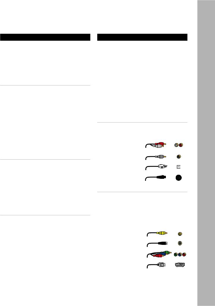
About Audio Cables
•RCA Cables - Use for stereo audio connections. Match red to red and white to white.
•Digital coaxial cables - Use for digital audio connections.
• Digital optical cables
(aka “Toslink”) - Use as an alternative
to coaxial cable for digital audio connections.
•XLR cables - Use
for amplifier connections.
About Video Cables
•Video cables - Use for composite video connections. Match yellow to yellow.
•S-Video cable - Use for higher quality video connections to standard TVs and analog components.
•Component video cables - Use for best quality analog video connections to TVs and components. Match
green, blue, and red respectively.
•HDMI cables - Use
for superior, alldigital audio/video quality to and from HDMI compatible components.
Connections - 2 Chapter
www.adcom.com |
GTP-870HD Owner’s Manual |
13 |
Chapter 2 - Connections
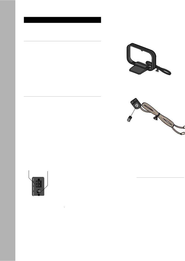
AM/FM Antenna Connections
Follow these steps to connect the supplied AM/FM antennas to the GTP-870HD.
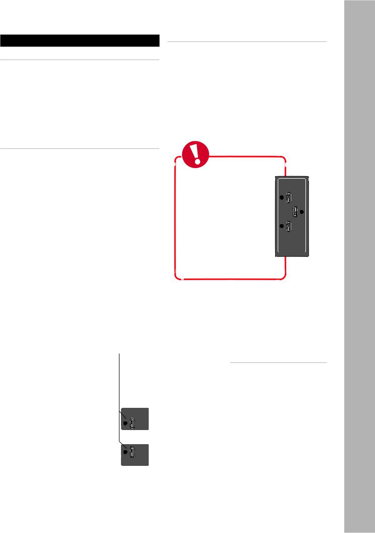
Connecting the AM Loop Antenna
1Assemble the antenna.
•Rotate the base until it snaps into place. 2 Connect the antenna.
•Locate the AM antenna inputs.
•Press the lever next to one of the terminals and insert one of the antenna leads into the terminal. Release the lever to lock the lead in place.
•Repeat for the other lead.
3Position the antenna for best reception.
•To mount the antenna permanently, use screws through the two holes in the base.
Connecting the FM Antenna
1Assemble the antenna.
• Connect the supplied adapter to the FM an-
tenna as shown.
2Connect the antenna.
•Locate the FM antenna input, and securely attach the FM adapter.
3Position the antenna for best reception.
•Fully extend the antenna and experiment with its position to obtain the strongest signal. You can attach it to a wall or other surface (e.g., using push pins).
•The supplied antenna is for indoor use only.
AM |
FM |
Antenna |
Antenna |
Input |
Input |
AM Loop Antenna
Adapter
FM Antenna
Notes:
•To switch to Tuner mode,
press the Tuner button on the remote control, or the FM/AM button on the front panel.
•For Tuner operations, see page
60.
14 |
GTP-870HD Owner’s Manual |
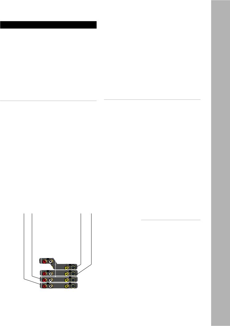
Basic Audio/Video Connections
This section provides a general connection method that is suitable for virtually any audio/video source component, including:
•DVD players
•Laser disc players
•CableTV boxes
•Satellite receivers
•HDTV set-top boxes
•VCRs (see notes below)
•PVRs
•Media PCs
•iPod docking stations
Connecting Audio/Video Components
1Choose a Video input (1~4) for your component. A typical scenario might be:
•Video 1 - DVD or Laser disc player.
•Video 2 - Digital set-top box (CableTV, satellite receiver, or HDTV tuner).
•Video 3 & 4 - Device with dual playback/recording capability (e.g., VCR, DVD Recorder, PVR, etc.).
2Connect video.
•Using a composite video cable, connect the video output on your source component to the video input on the GTP-870HD.
•For higher quality video, use an S-video cable to connect the S-video output on the source component to the S-video input on the GTP870HD.
3Connect audio.
•Using RCA cables, connect the audio outputs on your source component to the audio inputs on the GTP-870HD.
4Configure your input settings.
• See page 33.
For Advanced Connections:
Depending on the capabilities of your components, follow these links to add some sizzle to these basic connections:
•For upgraded DVD connections, see page 16.
•For Component/Progressive Scan video connections, see page 17.
•For digital audio connections, see page 18.
•For HDMI connections, see page 19.
•For recording connections, see pages 26 and 27.
Video 1 |
Video 2 |
Video 4 |
Video 3 |
Input |
Input |
Input |
Input |
Notes:
• If you plan to use a VCR as an input device, it MUST have an integral Time Base Corrector!
• To select the source component you connected, press the corresponding Video 1~4 button on the remote control or front panel.
• To configure your video source, see page 33.
• For basic audio/video playback operations, see page 56.
Connections - 2 Chapter
www.adcom.com |
GTP-870HD Owner’s Manual |
15 |
Chapter 2 - Connections
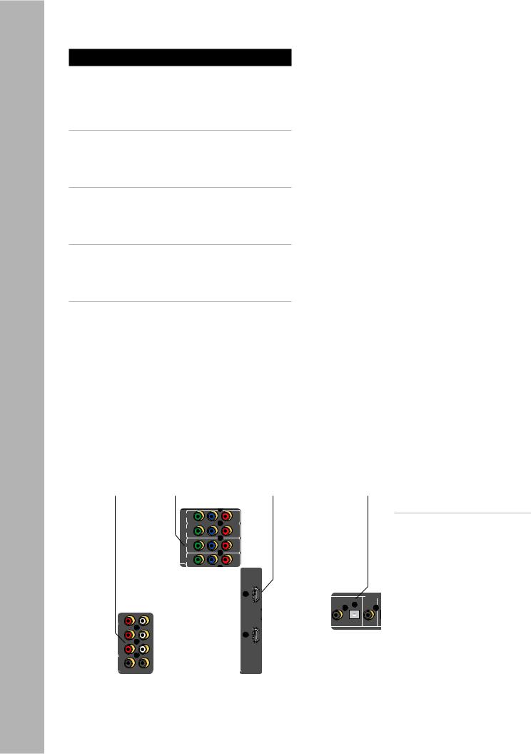
DVD Player Connections
The GTP-870HD is a movie lover’s dream. Choose from the following special options when connecting your DVD player.
Component/Progressive Scan Connections
To take the video quality up a notch, use your DVD player’s Component/Progressive Scan outputs.
•See page 17.
Digital Audio Connections
For crystal-clear multi-channel digital audio, use your DVD player’s digital audio outputs.
•See page 18.
HDMI Connections
If your DVD player supports HDMI, you’re in for an all-digital audio/video feast.
•See page 19.
External 7.1 Connections
If your DVD player supports DVD-Audio or SACD playback, use the External 7.1 inputs.
•See page 20.
|
Component/ |
|
Ext. 7.1 |
Progressive |
|
Audio |
Scan Video |
HDMI |
Inputs |
Inputs |
Inputs |
Digital
Audio
Inputs
Notes:
•These superior quality connec-
tions are covered in detail on pages 17-20.
16 |
GTP-870HD Owner’s Manual |
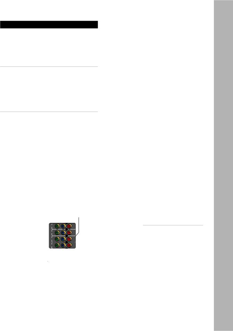
Component/Progressive Scan Connections
The GTP-870HD features four Component video inputs for connection to DVD players, digital CableTV boxes, digital satellite receivers, HDTV receivers/ tuners, and more. Component video is the best quality analog connection method to an HDTV display.
Special Note on Progressive Scan DVD Players
If you want to use the GTP-870HD’s built-in video scaling capability, you MUST set the output of your Progressive Scan DVD player to standard 480i resolution. Extended Definition (480p) and High Definition analog sources connected to the component video inputs are “bypassed” (i.e., sent to the component output) as is—NOT scaled.
Component/Progressive Scan Connections
1Choose an available Component Video input
(1~4).
2Connect Component video cables.
•Using a set of Component video cables, connect the Y/Pb/Pr outputs on your source device to the corresponding Y/Pb/Pr inputs on the GTP-870HD.
•Be sure to match the red, green, and blue connectors accordingly.
Component Video/
Progressive Scan
Inputs
Connections - 2 Chapter
Notes:
•To select the Component/Progressive Scan inputs, press the corresponding Video 1~4 button on the remote control or front panel.
•To connect the Component/ Progressive Scan outputs to your TV, see page 22.
www.adcom.com |
GTP-870HD Owner’s Manual |
17 |
Chapter 2 - Connections
Digital Audio Connections
The GTP-870HD features six digital audio inputs— three coaxial and three optical—to receive multichannel bitstreams from your DVD player or other digital audio source component.
Connecting Digital Audio Components
1 Choose an available digital audio input.
2Connect digital audio cable(s).
•Using a digital coaxial audio cable, connect the coaxial output on your source device to the corresponding coaxial input on the GTP870HD.
•Alternatively, use an optical (Toslink) cable to connect the optical output on your source device to the corresponding optical input on the GTP-870HD.
3Associate the digital audio input with a Video input.
•See page 33 to associate the digital audio input with the Video 1-4 or CD input.
Coaxial |
Optical |
Digital Audio |
Digital Audio |
Inputs 1~3 |
Inputs 1~3 |
Notes:
•The digital audio inputs are assignable to the Video 1-4 or CD inputs; see page 33.
18 |
GTP-870HD Owner’s Manual |
HDMI Connections
About HDMI
HDMI (High Definition Multimedia Interface) is an advanced audio/video connection method that transfers full-bandwidth, uncompressed digital audio and video signals over a single cable.
As a result, pure digital signals can pass unfettered from your HDMI-compatible source components to the GTP-870HD and out to your digital TV for superior picture and sound quality.
About the HDMI Scaler
The GTP-870HD is more than just a switch for HDMI source components. The GTP-870HD comes with a built-in scaler, a powerful video signal processor that allows you to scale the 480i or 576i NTSC/PAL inputs of your source components and output the precise resolution for your display device up to 1080p.
That means you can run your legacy video sources through the GTP-870HD to your HDMI display device through a single cable. The powerful, integrated processor deinterlaces and scales standard NTSC/PAL signals to the native resolution of your display .
HDMI
Inputs
Connecting HDMI Components
1 Choose an available HDMI input.
2Connect HDMI cable(s).
•Using an HDMI cable, connect the HDMI output on your source device to one of the HDMI inputs on the GTP-870HD.
3Assign the HDMI input to an input source and configure it.
• See pages 33-35.
4Connect the HDMI output to your TV.
• See page 22.
Tip
The HDMI connections pass both audio and video signals from your source device to your output device;however,to use the full audio processing power of the GTP-870 we recommend
that you connect a separate audio cable (analog or digital) from your source device to the appropriate input on the GTP-870.See page 15 for analog audio connections or page 18 for digital audio connections.
Notes:
•The HDMI inputs are assignable to any source; see page 33.
•To connect the HDMI output to
your TV, see page 22.
Connections - 2 Chapter
www.adcom.com |
GTP-870HD Owner’s Manual |
19 |
Chapter 2 - Connections
External Decoder Connections
If you’re a true audiophile, you’re probably familiar with DVD-Audio and SACD, multi-channel audio formats that require their own decoding and unique connection methods. Follow these steps to connect a DVD, DVD-A, or SACD player with up to 7.1-channel analog outputs.
Connecting a DVD-A/SACD Player
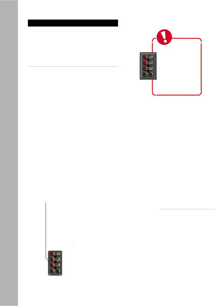
1Using eight RCA cables, connect the 7.1 channel analog audio outputs from your DVD player to the corresponding Ext 7.1 inputs on the GTP-870HD.
2If your DVD player has 5.1-channel analog outputs, use six RCA cables and omit the RB and LB connections.
Ext. 7.1
Inputs
Tip
The External 7.1 inputs bypass the internal Analog to Digital Converter.
As a result,they can also be used as a “high-end” analog 2-channel input for those who desire a ‘direct’analog input.
Notes:
•To switch to External 7.1 mode, press the Ext 7.1 button on the remote control or front panel.
•For Ext 7.1 operations, see page 56.
20 |
GTP-870HD Owner’s Manual |
CD/Tape Player Connections
Follow these steps to connect a CD or tape player to the GTP-870HD.
Connecting a CD Player
1Using RCA cables, connect the audio outputs on your CD player to the CD inputs on the GTP870HD.
•If your CD player is equipped with a digital audio output (e.g. to play back a DTS CD), see Digital Audio Connections on page 18.
Connecting a Tape Player
1Using RCA cables, connect the audio outputs on your tape player to the Tape inputs on the GTP870HD.
Tape |
CD |
Input |
Input |
Connections - 2 Chapter
Notes:
•To switch to CD mode, press the CD button on the remote control or front panel.
•To switch to Tape mode, press the Tape button on the remote control or front panel.
•For CD configuration settings, see page 33.
•For CD operations, see page 56.
•For digital audio connections, see page 18.
www.adcom.com |
GTP-870HD Owner’s Manual |
21 |
Loading...