


OWNER’S MANUAL
GFA-7805 & GFA-7807
Multi-channel High-Current PowerAmplifiers

WELCOME
Dear fellow ADCOM product owner,
Welcome to the ADCOM family! For more than twenty years, ADCOM products have delivered excellent performance and value for customers around the world. Our products are designed by our experienced and demanding engineering team, built to the highest standards in our factory, and sold and serviced through dealers, custom installers, and other retailers whose primary goal is your complete satisfaction.
We know you are anxious to hear your new amplifier in action, but please take a few minutes to read this owner’s manual before connecting the amplifier to your system. Because ADCOM amplifiers can put out tremendous power, it is particularly important that you connect your amplifier to your pre-amplifier and speakers while the amplifier is unplugged and your other equipment is turned off. This will protect the amplifier and other equipment from potential short circuits that may occur during installion. In addition, it is important that you allow for adequate ventilation around your amplifier and other equipment, since excessive heat buildup can shorten the life of any electronic product, including the amplifier. Once you have correctly connected your pre-amplifier and speakers to your new amplifier, you should be able to enjoy many troublefree years of performance.
We conduct a thorough quality and performance test on each and every amplifier we build in our factory prior to shipment. In the rare case of a defect that may occur after shipment, we stand behind our amplifiers with a five-year parts and labor warranty. To register for this warranty, please complete and mail the enclosed warranty card back to ADCOM. Also, please keep a copy of your sales receipt with the owner’s manual so you may provide proof of eligibility for the warranty should the need arise.
We know you will be very happy with the sound and performance of your new amplifier. We hope you will also consider other ADCOM products, such as our line of pre-amplifiers and DVD and CD players. In addition, we design and manufacture complementary products such as line conditioners/surge suppressors and speaker selectors. Please visit our web site, www.adcom.com, to learn more about our complete line of stereo, home theater, and distributed audio/video products.
On behalf of all of us at ADCOM, I want to thank you for selecting our product for your home or business entertainment system.
Sincerely,
Douglas Klein
President
ADCOM
2
TABLE OF CONTENTS
WELCOME ........................................ |
2 |
SAFETY INFORMATION ........................... |
4 |
DESCRIPTION OF UNIT |
|
GFA-7805 FEATURES .............................. |
5 |
GFA-7807 FEATURES .............................. |
5 |
WARRANTY INFORMATION ......................... |
5 |
INSTALLATION & HOOKUP |
|
UNPACKING THE GFA-7805/7807 .................. |
6 |
INSTALLING THE GFA-7805/7807 .................. |
6 |
OPERATION |
|
FRONT AND REAR PANEL DIAGRAMS ................ |
7 |
DESCRIPTION OF UNIT: REAR PANEL ............... |
8 |
DESCRIPTION OF UNIT: FRONT PANEL ............ |
8-9 |
CONNECTIONS DIAGRAM ......................... |
10 |
CONNECTING THE GFA-7805/7807 ................ |
11 |
TROUBLESHOOTING |
|
RESOLVING PROBLEMS ........................... |
12 |
CARING FOR YOUR GFA-7805/7807 ............... |
13 |
SERVICE INFORMATION .......................... |
13 |
GFA-7805 SPECIFICATIONS ....................... |
14 |
GFA-7807 SPECIFICATIONS ....................... |
15 |
THE FOLLOWING PRECAUTIONS AND SAFETY INSTRUCTIONS ARE REQUIREMENTS OF UL AND CSA SAFETY REGULATIONS
Warning: To reduce the risk of fire or electric shock, do not expose this unit to rain or moisture.
CAUTION |
RISK OF ELECTRIC SHOCK |
DO NOT OPEN |
The graphic symbol of a lightning flash with an
arrow point |
within a triangle signifies that there |
is dangerous |
voltage within the unit and it poses |
a hazard to anyone removing the cover to gain access to the interior of the unit. OnIy qualified service personnel should make any such attempt.
The graphic symbol of an exclamation point within an equilateral triangle warns a user of the device that it is necessary to refer to the instruction manual and its warnings for proper operation of the unit.
Donotplacethisunitonanunstablecart,stand,tripod, bracket, or table. The unit may fall, causing serious injury to a child or adult, and serious damage to the unit. Use only with a cart, stand, tripod, bracket, or table recommended by the manufacturer or sold with the unit. Any mounting of the device should follow the manufacturer’sinstructions,andshoulduseamounting accessory recommended by the manufacturer.
Read all the safety and operating instructions before connecting or using this unit.
Retain this notice and the owner’s manual for future reference.
All warnings on the unit and in its operating instructions should be adhered to.
All operating and use instructions should be followed.
Do not use this unit near water. For example, near a bathtub, washbowl, kitchen sink, laundry tub, in a wet basement, or near a swimming pool.
The unit should be installed so that its location or position does not interfere with its proper ventilation. For example, it should not be situated on a bed, sofa, rug, or similar surface that may block the ventilation openings; or placed in a built-in installation, such as bookcase or cabinet, that may impede the flow of air through its ventilation openings.
The unit should be situated away from heat sources such as radiators, heat registers, stoves, or other devices (including amplifiers) that produce heat.
The unit should be connected to a power supply outlet only of the voltage and frequency marked on its rear panel.
The power supply cord should be routed so that it is not likely to be walked on or pinched, especially near the plug, convenience receptacles, or where the cord exits from the unit.
Clean unit only as recommended in its instruction manual.
The power supply cord of the unit should be unplugged from the wall outlet when it is to be unused for a long period of time.
Care should be taken so that objects do not fall, and liquids are not spilled, into the enclosure through any openings.
This unit should be serviced by qualified service personnel when:
A.The power cord or the plug has been damaged; or
B.Objects have fallen, or liquid has been spilled, into the unit; or
C.The unit has been exposed to rain, or liquids of any kind; or
D.The unit does not appear to operate normally, or exhibits a marked change in performance; or
E.The device has been dropped, or the enclosure damaged.
DO NOT ATTEMPT SERVICING OF THIS UNIT YOURSELF. REFER SERVICING TO QUALIFIED SERVICE PERSONNEL.
ATTENTION
POUR PREVENIR LES CHOCS ELECTRIQUES NE PAS UTILISER CETTE FICHE POLARISEE AVEC UN PROLONGATEUR, UNE PRISE CE COURANT OU UNE AUTRE SORTIE CE COURANT, SAUF SI LES LAMES PEUVENT ETRE INSEREES A FOND SANS EN LAISSER AUCUNE PARTIE A DECOUVERT.
CAUTION
TO PREVENT ELECTRIC SHOCK DO NOT USE THIS POLARIZED PLUG WITH AN EXTENSION CORD, RECEPTACLE OR OTHER OUTLET UNLESS THE BLADES CAN BE FULLY INSERTED TO PREVENT BLADE EXPOSURE.
CAUTION POWER LINES
Any outdoor antenna must be located away from all power lines.
OUTDOOR ANTENNA GROUNDING
If an outside antenna is connected to your tuner or tuner/preamplifier, be sure the antenna system is grounded so as to provide some protection against voltage surges and built-up static charges. Section 810 of the National Electrical Code, ANSI/NFPA No. 701984, provides information with respect to proper grounding of the mast and supporting structure, grounding of the lead-in wire to an antenna discharge unit, size of grounding conductors, location of antenna discharge unit, connection to grounding electrodes, and requirements for the grounding electrode.
a.Use No.10 AWG (5.3 mm2) copper, No.8 AWG (8.4 mm2) aluminum, No.17 AWG (1.0 mm2) copper clad steel or bronze wire, or larger, as a ground wire.
b.Secure antenna lead-in and ground wires to house with stand-off insulators spaced from 46 feet (1.221.83 m) apart.
c.Mount antenna discharge unit as close as possible to where lead-in enters house.
d.Use jumper wire not smaller than No.6 AWG (13.3 mm2) copper, or the equivalent, when a separate antenna grounding electrode is used. See NEC Section 810-21 (j).
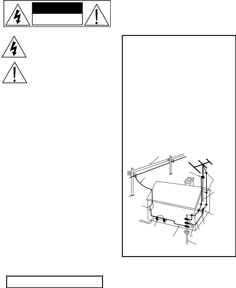
EXAMPLE OF ANTENNA GROUNDING AS PER NATIONAL ELECTRICAL CODE INSTRUCTIONS CONTAINED INARTICLE 810. RADIOAND TELEVISION EQUIPMENT.
power lines
ground clamp
service entrance conductors
service entrance equipment
ground wire, a,b ground clamps 
power service grounding electrode system
(e.g. interior metal water pipe)
bonding jumper, d
standoff insulators, b
mast
antenna  lead-in wire
antenna discharge unit, c
to external antenna terminals of radio receiver
ground wire, a,b ground clamps
optional antenna grounding electrode driven 8 feet (2.44 M) into the earth if required by local codes.
NOTE TO CATV SYSTEM INSTALLER
This reminder is provided to call the CATV system installer’s attention to Article 82022 of the National Electrical Code that provides guidelines for proper grounding and, in particular, specifies that the cable ground shall be connected to the grounding system of the building, as close to the point of cable entry as practical.
GFA-7805 FEATURES
•Precision-matched devices used throughout the signal path
•112,000 µF of power supply-filter capacitance to optimize transient response
•Independent power supplies for each channel
•Fewer gain stages improve signal reproduction accuracy
•Custom toroidal power transformer provides better regulation and greater peak current capability
•Independent thermal-overload and distortion LEDs for all 5 channels
•High quality, gold-plated 5-way binding posts
•Balanced XLR inputs
•High quality, gold-plated RCA jacks
•Large independent internal heatsinks for greater cooling capability of output devices
•Convenient 12V DC power ON/OFF triggering
•Heavy gauge, anodized aluminum front panel
•Powder-coated, baked chassis and top cover for greater durability
•Cooling vents for greater efficiency and cooler operation while driving low impedance loads
•Forced convection temperature sensitive cooling
GFA-7807 FEATURES
•Precision-matched devices used throughout the signal path
•156,800 µF of power supply-filter capacitance to optimize transient response
•Independent power supplies for each channel
•Fewer gain stages improve signal reproduction accuracy
•Custom toroidal power transformer provides better regulation and greater peak current capability
•Independent thermal-overload and distortion LEDs for all 7 channels
•High quality, gold plated 5-way binding posts
•Balanced XLR inputs
•High quality, gold-plated RCA jacks
•Large independent, internal heatsinks for greater cooling capability of output devices
•Heavy gauge, anodized aluminum front panel
•Powder-coated, baked chassis and top cover for greater durability
•Cooling vents for greater efficiency and cooler operation while driving low impedance loads
•Forced convection temperature sensitive cooling
ADCOM PROTECTION PLAN (USA Only)
ADCOM offers the enclosed valuable Limited Warranty. Please read the details on the Warranty Card carefully to understand the extent of the protection offered by the Warranty, its reasonable limitations, and what you should do in order to obtain its benefits. Be sure to verify that the serial number printed on the rear panel matches the serial number on the outer carton. If any number is altered or missing, or if the ADCOM Warranty Card is not included in the carton, you should notify us immediately in order to ensure that you have received a genuine ADCOM product which has not been opened, mishandled, or tampered with in any way. Always retain your original sales receipt as a proof of purchase.
5
 Loading...