

Page 1

/DOOM
details you can hear
GSP-560
Surround Sound
Processor/Amplifier
OWNER’S MANUAL
Page 2
THE FOLLOWING PRECAUTIONS AND SAFETY INSTRUCTIONS
ARE REQUIREMENTS OF UL AND CSA SAFETY REGULATIONS
Warning; To reduce the risk of fire or eiectric shock, do not expose
this unit to rain or moisture.
CAUTION
RISK OF ELECTRiC SHOCK
A
DO NOT OPEN
AVIS: RISQUE DE CHOC ELECTRIQUE-NE PAS OUVRIR
The graphic symbol of a lightning flash with an arrow
point within a triangle signifies that there is dangerous
voltage within the unit and it poses a hazard to anyone
removing the cover to gain access to the interior of the
unit Only qualified service personnel should make
any such attempt.
The graphic symbol of an exclamation point within an
equilateral triangle warns a user of the device that it is
necessary to refer to the instruction manual and its
warnings for proper operation of the unit
Do not place this unit on an unstable cart, stand, tripod,
bracket, or table The unit may fall, causing serious
injury to a child or adult, and serious damage to the
unit Use only with a cart, stand, tripod, bracket, or table
recommended by the manufacturer, or sold with the
unit Any mounting of the device should follow the man
ufacturer’s instructions, and should use a mounting ac
cessory recommended by the manufacturer.
Read all the safety and operating instructions before connecting or using
this unit
Retain this notice and the owner’s manual for future reference
All warnings on the unit and in its operating instructions should be adhered to
All operating and use instructions should be followed
Do not use this unit near water, for example, near a bathtub, washbowl,
kitchen sink, laundry tub, in a wet basement, or near a swimming pool
Ì
ATTENTION
POUR PRÉVENIR LES CHOCS ÉLECTRIQUES NE PAS UTILISER
CETTE FICHE POLARISÉE AVEC UN PROLONGATEUR, UNE PRISE
DE COURANT OU UNE AUTRE SORTIE DE COURANT, SAUF SI LES
LAMES PEUVENT ÊTRE INSÉRÉES À FOND SANS EN LAISSER AU
CUNE PARTIE À DÉCOUVERT
CAUTION
TO PREVENT ELECTRIC SHOCK DO NOT USE THIS POLARIZED PLUG
WITH AN EXTENSION CORD, RECEPTACLE OR OTHER OUTLET UN
LESS THE BLADES CAN BE FULLY INSERTED TO PREVENT BLADE
EXPOSURE
CAUTION
POWER LINES
Any outdoor antenna must be located away from all power lines.
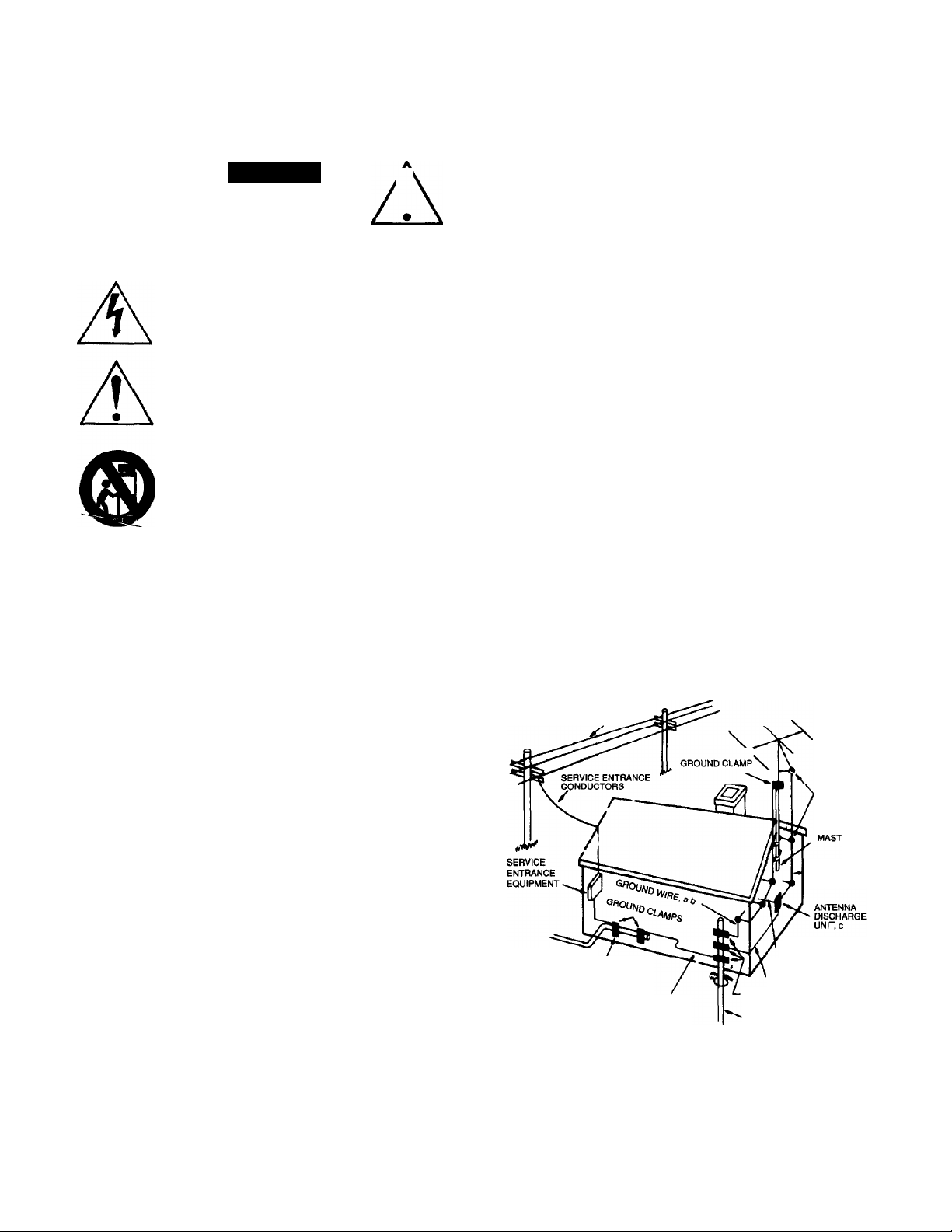
OUTDOOR ANTENNA GROUNDING
if an outside antenna is connected to your tuner or tuner-preamplifier, be
sure the antenna system is grounded so as to provide some protection
against voitage surges and built-up static charges. Section 810 of the
National Electrical Code, ANSI/NFPA No. 70-1984, provides information with
respect to proper grounding of the mast and supporting structure, grounding
of the lead-in wire to an antenna discharge unit, size of grounding
conductors, location of antenna discharge unit, connection to grounding
electrodes, and requirements for the grounding electrode.
a. Use No.10 AWG (5.3 mm®) copper, No.8 AWG (8.4 mm®) aluminum.
No.17 AWG (1.0 mm®) copper-clad steel or bronze wire, or larger, as a
ground wire
b. Secure antenna lead-in and ground wires to house with stand-off
insulators spaced from 4-6 feel (1.22-1.83 m) apart.
c. Mount antenna discharge unit as close as possible to where lead-in
enters house.
d. Use jumper wire not smaller than No.6 AWG (13.3 mm®) copper, or the
equivalent, when a separate antenna-grounding electrode is used. See NEC
Section 810-21 Q).
EXAMPLE OF ANTENNA GROUNDING AS PER NATIONAL ELECTRICAL CODE INSTRUCTIONS
CONTAINED IN ARTICLE 810 - RADIO AND TELEVISION EQUIPMENT
The unit should be installed so that its location or position does not intertere
with Its proper ventilation For example, if should not be situated on a bed,
sofa, rug, or similar surface that may block the ventilation openings, or
placed in a built-in installation, such as bookcase or cabinet, that may
impede the flow of air through its ventilation openings.
The unit should be situated away from heat sources such as radiators, heat
registers, stoves, or other devices (including amplifiers) that produce heat
The unit should be connected to a power-supply outlet only of the voltage
and frequency marked on its rear panel
The power-supply cord should be routed so that it is not likely to be walked
on or pinched, especially near the plug, convenience receptacles, or where
the cord exits from the unit
Clean unit only as recommended in its instruction manual
The power-supply cord of the unit should be unplugged from the wall outlet
when It IS to be unused for a long period of time
Care should be taken so that objects do not fall, and liquids are not spilled,
into the enclosure through any openings
This unit should be sen/iced by qualified service personnel when
A The power cord or the plug has been damaged; or
B Objects have fallen, or liquid has been spilled, into the unit, or
C The unit has been exposed to ram, or liquids of any kind, or
D The unit does not appear to operate normally, or exhibits a
marked change in performance; or
E The device has been dropped, or the enclosure damaged
DO NOT ATTEMPT SERVICING OF THIS UNIT YOURSELF.
REFER SERVICING TO QUALIFIED SERVICE PERSONNEL.
POWER LINES
STANDOFF
INSULATORS, b
ANTENNA
LEAD-IN WIRE
TO EXTERNAL ANTENNA
POWER SERVICE GROUNDING
ELECTRODE SYSTEM
(e g intenor metal water pipe)
BONDING JUMPER, d
OPTIONAL ANTENNA GROUNDING
ELECTRODE DRIVEN S FEET (2 44 M) INTO
THE EARTH IF REQUIRED BY LOCAL
CODES SEE NEC SECTION 810-21 (f)
NOTE TO CATV SYSTEM INSTALLER
This reminder is provided to call the CATV system installer’s attention to
Article 820-22 of the National Electrical Code that provides guidelines for
proper grounding and, in particular, specifies that the cable ground shall be
connected to the grounding system of the building, as close to the point of
cable entry as practical
TERMINALS OF RADIO RECEIVER
GROUND WIRE, a.b
GROUND CLAMPS
Page 3

INTRODUCTION
Congratulations on your decision to purchase the ADCOM GSP-560 Surround Sound Processor/Amplif ler. We thinkyou’ve
made a wise choice The GSP-560 is the first product of its type to combine advanced Dolby Pro Logic decoding circuitry,
simplified controls and award winning amplification, In short, the GSP-560 brings aud loph ile standards to the world of home
theater.
Enjoy your movies'
A NOTE ON YOUR OWNER’S MANUAL
In a hurry'? The QUICKSTARTSection will soon have you up and running However, we strongly recommend that you
refer to the expanded instructions in EVERYTHING YOU NEED TO KNOW to "fine tune" your system for enhanced
enjoyment once everything is working.
If you're more patient or want more background, start with EVERYTHING YOU NEED TO KNOW. You’ll be rewarded with
a much better understanding of how the GSP-560 works and what its capabilities are
This unit is manufactured under license from Dolby Laboratories
Licensing Corporation. It is additionally licensed under one or more of
the following patents. U.S. number 3,959,590; Canadian numbers
1,004,603 and 1,037,877 "Dolby,” “Pro Logic,” and the double-D
symbol are trademarks of Dolby Laboratories Licensing Corporation.
Page 4
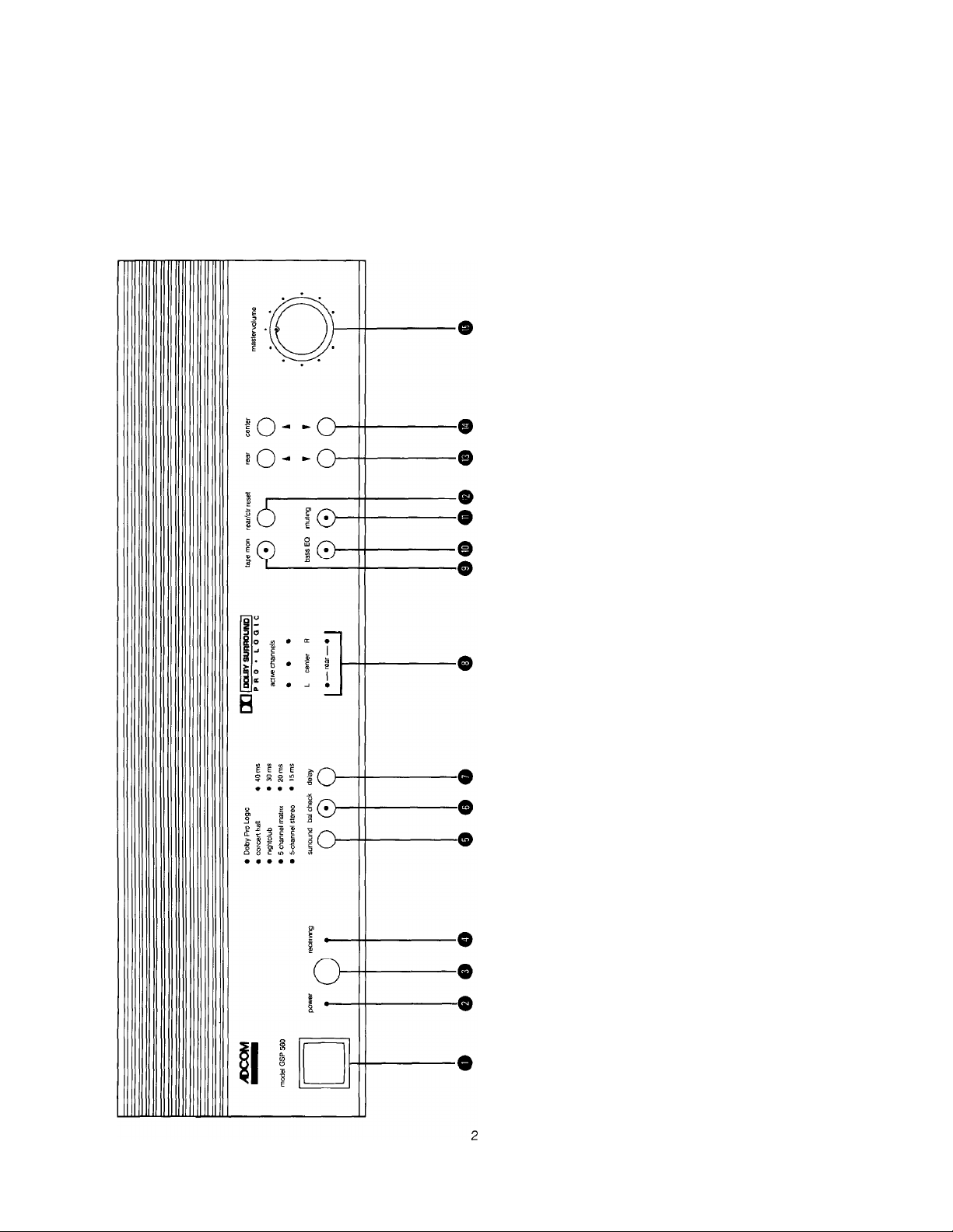
FRONT and REAR PANELS
We carefully designed the GSP-560 with your enjoyment in mind Controls are at a minimum and we've arranged them in
functional groups so that their use is almost intuitive The rear panel also benefits from the same design goals Take a
momentto familiarize yourself with them You’llfindreferencestothecircledIDnumbersthroughouttherestofthismanual
GSP - 560 FRONT PANEL DIAGRAM
o
Q
O
CD
Q
C/5
QL
0)
QC
k—
_0)
c
CD
O)
CJ
c
CO
CD
q:
0 0 0 0 0
D
CD
>
CD
CC
CD
cr
0
£
03
>
o
CD
>
CO
c
CD
CD
O
C
o
o
13
o
JD
o
sz
C/Ì
o
Z3
CO
CL
k.
o
2
<D
o
2
O
CP
CD
CO
O
c
CD
CD
CD
Q
o o o o ©
Q
LU
O
it:
ro
O
Q
T3
c
c
O
o3
5
o
o
CL
Q.
e o
CO
Q
LU
—I
Q.
03
Q
o3
c
c
CD
JZ
O
0
>
o
<
o
■a
c
o
CP
c
CD
CO
cz
o
0
Q.
CD
Q
LU
_J
O)
c
>
0
o
0
□:
e e
o
CO
CO
03
CQ
o
o
_0
0
CO
■Q
c
D
O
k_
k_
CO
Page 5
o
0)
■0
Cl
S
jj
m
>
J3
z
m
I"
g
>
o
JJ
>
00
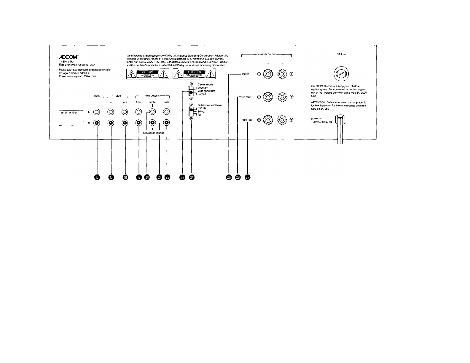
0 Mam Inputs (L&R)
0 Tape Inputs (L&R)
0 Tape Outputs (L & R) © Line Outputs - Rear (L & R)
0 Line Outputs - Front (L & R)
© Line Output - Center
0 Line Output - Subwoofer (mono) © Speaker Output - Center
© Center Mode Switch
© Subwoofer Crossover Switch
© Speaker Output - Left Rear
© Speaker Output - Right Rear
Page 6

GSP - 560 REMOTE CONTROL
® Power On/Off
® Muting
0 Surround
0 Delay
0 Tape Monitor
0 Bass EQ
0 Rear/Center Reset
0 Balance Check
© Volume - Up/Down
0 Subwoofer Level - Up/Down
© Center Level - Up/Down
0 Rear Level - Up/Down
QUICK START
1) Unpack the GSP-560 carefully MAKE SURE YOU REMOVE THE REMOTE CONTROL FROM THE BOX. Put the
foam cocoon and other packing materials back in the carton and save it if at all possible
2) Selectastable, vibration-free location fortheGSP-560ascloseaspossibletoyourotheraudioand videocomponents.
REMEMBER THAT THE GSP-560 HAS THREE HIGH CURRENT AMPLIFIERS INSIDE! Make sure you have
enough air space for proper ventilation.
3) Turn off all the other components in your system. That means everything. And don’t plug the GSP-560 into the AC
outlet yet
4) If your system’s control center (a receiver, integrated amplifier, or preamplifier) has connections designed for an
external signal processor, follow these steps. If not, go to QUICKSTARTParagraph 5 below.
a) Connect your control center’s Processor Out jacks to the GSP-560’s “Main Input” jacks 0 These are to the far
left of the jack array on the GSP-560’s rear panel.
b) Connect your oontrol center’s Processor In jacks to the GSP-560’s “Line Outputs - Front” 0 jacks
c) Activate the control center’s Processor loop by engaging the appropriate switch
5) It your control center does not have external processor connections, use the tape jacks instead
a) If you have a tape deck connected to your control center’s Tape In and Tape Out jacks (sometimes marked Play
and Record respectively), remove these connections.
b) Connect your control center’s Tape Out jacks to the GSP-560’s “Main Input” jacks 0 These are to the far left of
the jack array on the GSP-560’s rear panel.
c) Connect the GSP-560’s “Line Outputs - Front” 0 to your control center’s Tape In jacks.
d) Reconnect your tape deck to the GSP-560’s “Tape In”
0
and “Tape Out” 0 jacks
Page 7

e) Put the Tape Monitor switch on your control center to the “In” or active position
f) Use the GSP-560’s “Tape Monitor” pushbuttons (0on the front panel and ® on the remote controller) as needed
to play or monitor a tape
6) If you have a center channel speaker
a) Connect the speaker to the GSP-560’s “Speaker Outputs - Center” binding posts ® Make sure you connect
the “+” or red terminal on the GSP-560 to the “+” terminal on the speaker Then connect the GSP-560’s or black
terminal to the terminal on the speaker
b) Make sure the “Center Mode” switch ® on the rear panel is in either the “Wide” or “Normai” position (See
EVERYTHING YOU NEED TO KNOWior details )
7) If you do NOT have a center channel speaker, make sure that the “Center Mode” switch ® is in the “Phantom”
position
We strongly suggest a center channel speaker You’ll find it makes dialog more intelligible and increases system
flexibility (Again, see EVERYTHING YOU NEED TO KNOWior details )
8) Connect the two rear speakers to the “Speaker Outputs - Left Rear” ® and “Speaker Outputs - Right Rear” ®
binding posts respectively Observe the same polarity continuity (“+” to “+” and to outlined in Paragraph 6a
above
9) Make sure the “Master Voiume” control on the GSP-560 Q and the gam control on the control center are turned
down
10) Plug the GSP-560 into an AC outlet and turn it on by pressing the “Power” switch O Then turn the other system
components on
11) Turn your control center’s gam control to the position you normally use for comfortable listening.
12) Turn the GSP-560’s “Master Voiume” ® control clockwise to about 10 o’clock. THIS ISN’T A HARD AND FAST
RULE—you’ll know if you need to move this adjustment up or down a bit higher after you’ve started Step 14 below
13) Verify that you’re in Dolby Pro Logic mode by making sure that the appropriate LED (the one to the left of “Dolby Pro
Logic Surround”) is lighted If some other mode is indicated, press the “Surround” pushbutton 0 until the Dolby
ProLogic LED lights
14) Activate the GSP-560’s Balance Check circuit by pressing the “Bal Check” pushbutton 0 on the front panel
15) AdjusttheGSP-560’scenterandrearchanneloutputssothatthe sequential “rushingwater” noise isequally loud when
heard through each speaker Sit in yourfavorite chair and use the remote control for these adjustment (See Paragraph
15 in EVERYTHING YOU NEED TO KNOW for details.)
16) Turn off the sequential test tone by pushing the “Bai Check”
0
control again
17) Remember that the GSP-560’s “Master Voiume” control is now the volume control for the entire system If you
inadvertently move your control center’s gam adjustment after you've gone through the balancing process outlined
in Paragraph 15 above and detailed m Paragraph 15 of EVERYTHING YOU NEED TO KNOW, you’ll have to
rebalance for optimal listening
18) Select your source material and enjoy'
EVERYTHING YOU NEED TO KNOW
This section uses the same paragraph numbers as the preceding QUICKSTARTsechon We hope you tind the additional
information useful and enjoyable
1) PACKING MATERIAL
As part of ACCOM’s quality control procedures, yourGSP-560 was carefully inspectedfor physical imperfections and
electrical performance before it leftour plant In theevent of physical damage, notify your ACCOM dealer immediately
and request help in filing a written damage claim
Page 8

THE RIGHT TO A CLAIM AGAINST A COMMON CARRIER CAN BE FORFEITED IF THE CARRIER IS NOT
NOTIFIED PROMPTLY IN WRITING AND IF THE SHIPPING CARTON AND PACKING MATERIALS ARE NOT
AVAILABLE FOR INSPECTION. SAVE ALL PACKING MATERIALS UNTIL THE CLAIM HAS BEEN SETTLED.
The foam cocoon and carton were specifically designed to protect your GSP-560 Even though space is often at a
premium in today’s homes, we recommend that you save the packing materials in case you need to ship the unit
anywhere in the future
2) INSTALLING
The GSP-560 is heavier than you might expect due to the high capacity toroidal transformer and large heat sink
assembly forthepoweramplifiers Astable supporting surface is necessary We won’t go into the endless and mostly
unproven theories about extraneous vibrations and their deleterious effects on audio/video components except to
say that the more massive and firmly anchored the supporting surface is, the less likely you’ll be to experience any
problems.
Proper airflow is important. Don’t block the ventilation slots on the bottom plate and top cover of the unit. The feet
will insure enough air space below the GSP-560 for adequate circulation DO NOT STACKOTHER UNITS ON TOP
OF THE GSP-560. We recommend 4" of open space above the GSP-560 to allow for cooling.
3) SAFETY
Turning off system components before initial installation and connection avoids the nasty buzzes, thumps and other
sounds of electronic distress that occasionally accompany hooking up components Remember to give any power
amplifiers sufficient time to fully discharge their power supplies before you begin your connections. 30 seconds after
turn-off IS usually sufficient.
4~5) LINE LEVEL CONNECTIONS
Patience and common sense will help to avoid almost all of the errors you might make during the initial installation
Rememberto connect LeftChannel to Left Channel and Right Channel to Right Channel, etc. Thejacks on all ADCOM
products follow conventional color coding: White for Left Channel and Red for Right Channel. Most interconneot
cables observe this general guideline the connectors on each end of the cable are usually color coded.
We’ve received many questions about the sonic attributes of premium interconnect cables We do suggest that you
make sure any cable you use is a “low oapacitance’’ design (Most are ) Your ADCOM salesperson will be happy
to make cost-effective recommendations based on individual component characteristics and system complexity
6) CENTER CHANNEL SPEAKER CONNECTIONS
The “Center Mode” switch ® has three positions. The bottom two, “Wide Spectrum” and “Normai,” are important
here
“Wide Spectrum” sends afull range signal to the center channel speaker Use this position when your center channel
speaker is capable of extended bass reproduction and is acoustically similar to your mam left and right speakers
“Normai” restricts bass output (below 100 Hz) to the center channel speaker and redirects it to the mam left front
and rightfrontfull range speakers Use this position when you’ve chosen asmaller center channel speaker that might
not be capable of extended bass reproduction Under these circumstances, “Normal’’ reduces speaker distortion
and improves center channel clarity
NOTE: The center channel speaker is an essential component In a Dolby Pro Logic equipped home theater system.
It should be placed as close toyourTV screen as is physically possible and must be magnetically shielded to prevent
image distortion and possible damage to your picture tube.
In conjunction with Dolby Pro Logic’s “adaptive matrix” decoding, the center channel speaker improves coherency
by anchoring the soundfield to the screen’s Image Dialog, for example, always appears to be coming from yourTV
regardless of where you’re sitting in the room
Page 9

il”
îg'
If you’re not using a cen>tef'Channel speaker, piaee the “Centoi Mode” sft^itch® in the top or “Phantom” position.
This position ^Its tl^№l,pg|gd^p^||^centerchanndoutput bett^ both main speakers to synthesize a center
The “Phwttom" posttan ¡ywides anekcettent interim step in creating a home theater system. It allows you to benefit
from the improved toc^ii^iohinheriftitta'Pm Logic deciding; t-towever,'the “Phantom” position is not as effective
as using a center chanheLspeakeT; fnliiakssni&imagds are rrtafe vague spd ttey shift as you move about the room
rather thdrt bein^ ^rdem* Wattdng^reconwnpnd a^^ channel speaker. Your ADCOM dealer
’ ■■ ¡h . ..r
Rearspeaker^ ^
Pro Logic cteccdp^'ls'
processed' sgr#l|'dtStff péê®
This has led sxne pô(0e:t& pûùtde^fM'àufrowxf leakers dah be ine^nsfve •'atterthoughts* in a home theater
system. Such is definitely WOT thé ca«©. While Pro Logic processedYear channel information doesn’t contain
extended bass or treble, the surrodnd Speakers should tnm fairly flat frequency response over the required
bandwidth. Inex^nsf^ speakers ùètiaîly exhibit \^ry uneven or “peaky" fesponse that can älter the effects intended
by the creators of Dolby Surrdund'eftcbded'rmteridt. . :
i'll df“mUiWehc«iited material. However, the rear output of the
fhA'lhal» tiattt^r'speakers, at least when reproducing Pro Logic
1 nftjch lo^f than 1C30'te.#’’fhudh hi’^ier than 7 kHz
ij;
modes (“S CHannif Maffix” and “S Channel Sfereo“) that send full-bandwidth signals to the rear channels, Here,
severe speaker fimtetionS will be' even more dSvfous and detfimental. |Again, your ADCOM dealer will show you
appropriate choices. ' • -
Once you've chosen your rearchanrielspeakefs, the nextissi^ is placerrient - where doyou put them? Unfortunately
there are no hard and fa^ rules to make ybur if© easifer liere. Cenefsiy, tjie surround speakers should not be aimed
directly at you.' Cotnrrtbn' practice h^sthem widely spaced’high on the rear wall of your entertainment room. A
variation? Place them on the Sidewalls, sllghtlybehfnd arct above yourfavorite listening and watching position. Some
experitmentation Will probably be peiSassary. ' lfioyl ’’ '
woLuMisiQ«^^ : ' Y'"
Nothing to add here except fo port but that this is a standard safety|procedure designed to protect amplifiers,
speakers andibfcddrsefyoufearsinte unlikely event of amis-matched'connectionoramalfuhctioning component.
10) IWmLtURN-ON
When 5»u plug the GSP-560 into an AC outlet, an internal microprocessor automatically activates to control initial
operation. Pushing the front panel ‘Vower” switch ® or the ‘^ower”' button on the remote controller® turns the
unit on.i The^oiufer liuBcalw LED” ©changes from yellow (standby status) to red (fully operational status,) the
red LEDori tie “MatterVolume” control ©turns on, and all processor and amplifier stages are fully energized. After
a brief Interval to insure stebte operation, relays connect the line level stages to the rear panel RCA jacks and power
amptifierinputs. NdtethatADCOMdoesnotplacerelaysattheoutputoftheamptifiersthemselves. Ourconsiderable
experience suggesis that amplifier giiput relays inevitably malfunction or degrade sonic performance.
When theGSP-500 is’ttrfiiedoiff. Ihd rel%s open immediately to mute all fine outputs, including the internal connections
to the power amplifiers, -This protects agdinSt any transierit pops that may be unsettling.
Page 10

11) SOME NOTES ON VOLUME CONTROL USE
Once you've connected the GSP-560, a major functional change occurs in your system
The volume control of your original control center (preamplifier, integrated amp, or receiver) no longer adjusts total
system volume Instead, thatcontrolnowadjusts only front channel levels—the sound going to the left front and right
front speakers If you turn it down all the way, you'll still have output from the center and rear channels. Turning it up
all the way overshadows the center channel and therefore defeats the mam benefit of Pro Logic decoding Continued
use of this control will also alter the relative contibution of the rear channels to the overall soundfield, thereby reducing
the system's ability to recreate the sonic experience intended by the soundtrack’s creators
In effect, the level control on your system’s original control center SHOULD BE SET ONCE, THEN IGNORED. The
best way of doing this is to turn your control center's gam control to the position you previously associated with
comfortable to slightly loud listening. All subsequent adjustments will be done via the GSP-560’s front panel “Master
Volume” control O or the pushbuttons on the GSP-560’s hand held remote controller®
12) INITIAL LEVEL ADJUSTMENTS
Because the GSP-560’s “Master Volume” control increases or decreases levels to ALL outputs simultaneously, it
IS the new level control for the entire system
However, you still must adjust the relative levels of the center and rear channels (subwoofer, too, if you are using one)
before you’re completely ready.
To do this, turn the “Master Volume” control ® to about 10 o’clock. THIS ISN’T A HARD AND FAST RULE—you’ll
know if you need to change this adjustment a bit after you’ve started the procedure detailed In Paragraph 15 below
13) SELECT DOLBY PRO LOGIC MODE
Without going into endless details, the Pro Logic decoding 1C in the GSP-560 is designed to accurately recreate the
original soundfield intended by the creators of the Dolby Surround encoded media you will be playing
14) INTRODUCTORY NOTES ON THE BALANCE CHECK CIRCUIT
The Balance Check circuit does exactly what its name implies. An internal signal generator interrupts the normal
audio information and sends a test tone to all loudspeakers sequentially. The test tone is a filtered broadband signal
close in overall balance to the normal distribution of tones encountered in real life
DO NOT PLAY ANY OTHER SOURCE THROUGH THE GSP-560 WHEN USING THE BALANCE CHECK
CIRCUIT: if you need tooheck balances when playing a source, simply put the source on “Pause,” go through the
balance check routine explained in Paragraph 15, then resume playing the source
15) USING BALANCE CHECK
The goal of the balance check circuit is to enhance the spatial accuracy of your playback system by matching the
acoustic levelsof all system speakers in your room as closely as possible Once you’ve done this, any level differences
from left to center or from center to rear, etc , are differences intended by the creators of the original soundtrack, not
some unwanted aberration caused by the acoustics of your room
BECAUSE EVERY ROOM IS ACOUSTICALLY DIFFERENT AND THE RELATIVE CHANNEL-TO-CHANNEL
LEVELS WILL CHANGE AS YOU MOVE AROUND THE ROOM, WE STRONGLY RECOMMEND THAT YOU
PERFORM THIS CHECK FROM YOUR FAVORITE CHAIR USING THE GSP-560’S HAND HELD REMOTE
CONTROLLER.
a) Press the “Bal Check” button on the hand held remote controller® The tone generator will “step” through all
speakers sequentially beginning with the left front After approximately two seconds of left front output, the tone
will shift to the center channel
b) Use the “Center Level Up/Down” pushbuttons ® to adjust center channel output to match left channel volume
as closely as possible.
Page 11

c) After approximately two seconds, the center channel will mute and you’ll hear the test tone through the right front
speaker, probably at the same level as that of the left channel If left and right levels match, do nothing
If there IS a substantial difference between left front and right front outputs, correct the difference with your
control center’s balance control. Significant placement differences for left and right front speakers may cause
this imbalance Ideally, these speakers should be spaced symmetrically on either side of the TV screen If room
decor makes this placement difficult, or if you prefer to sit off-center from the TV screen, you may need left-right
balance correction
d) The test tone will shift to the rear speakers First, make sure that both rear speakers are functioning, then use the
“Rear Level Up/Down” pushbuttons ® to adjust the rear channel output to match that of the front left, center,
and front right speakers.
Remember to use the “Active Channel Display” O on the GSP-560's front panel as a visual reference. As the
tones cycle through all speakers, the Active Channel Display will indicate which speaker is currently receiving
the test tone
You’ll probably need to let the Balance Check test tones cycle through all speakers three orfour times until you’ve
matched levels closely Don’t worry about how quickly you can accomplish this balance adjustment—just take
your time and do it carefully
If you find yourself abit intimidated bythis procedure, rememberthatyou begin again simply by pushing the “Rear/
Center Reset” button 0. This will return all your gam adjustments to a neutral reference point From here, you
can start the level calibration process again. The front panel “Rear/Center Reset” button 0 serves the same
purpose
One note of caution Do not use either “Rear/Center Reset” button after you’re satisfied with channel-to-channel
balances. They are intended only to provide a reference point from which to START the balancing procedure
detailed here.
16) RESUMING NORMAL OPERATION
Push the “Bal Check” button ©again to turn off the test tone The GSP-560 is now ready for normal operation See
Paragraph 19 below for additional information on choosing the proper Surround and Delay options
17) MASTER VOLUME OPERATION
When you use the remote controller for volume, the GSP-560 will give you two visual clues that the circuit is operating
First, the “Receiving” LED on the front panel © will flash. The LED on the “Master Volume” knob ©will change color
from red to green as the knob moves in response to commands from the hand held controller Flowever, the LED will
NOT change color if you move the “Master Volume” knob by hand.
18) GETTING THE MOST OUT OF YOUR FAVORITE SOURCE MATERIAL
The GSP-560 IS an enormously flexible unit and will increase your enjoyment of a wide variety of audio and video
sources This section is the most subjective in the entire Owner’s Manual’ Feel free to take the suggestions here as
starting points for your own experimentation Above all, enjoyi
a) Choosing the proper Operating Mode
The GSP-560 provides six operating modes seiected by the “Surround” pushbutton on the front panel O or the
remote controller © These are Dolby Pro Logic, Concert Hall, Nightclub, 5 Channel Matrix, 5 Channel
Stereo and Bypass (2 channel stereo ) Each of the first five modes is indicated by an LED to the left of each mode
ID. In “Bypass” mode, no Mode LED lights.
DOLBY PRO LOGIC is the preferred mode for properly processing Dolby Surround encoded video soundtracks,
a growing number of CDs, and even the audio portion of some video games' in this mode, the GSP-560 presents
a spatially correct soundstage with precise lateral imaging and front to back depth
Rear channel delay choices 30.20. and 15 milliseconds (See 18B below for more information on delay )
Page 12

CONCERT HALL, recreates a fairly big and acoustically reverberant environment well suited for playback of full
orchestral works and other music that is usually performed in large indoor spaces
Rear channel delay choices 40 and 30 milliseconds.
NIGHTCLUB, synthesizes a smaller and more intimate soundfield ideal for many types of jazz and popular music
Rear channel delay choices- 20 and 15 milliseconds
5 CHANNEL MATRIX is ideal for mono sources — the soundtracks of older videotapes, for example — and
creates a dimensionally enhanced, diffuse soundfield for increased enjoyment
No rear channel delay is available in this mode
5 CHANNEL STEREO differs from the MATRIX mode in that no dimensional enhancement is performed 5
CHANNEL STEREO Simply sends a mono (L + R) signal to the center channel speaker. Left Front Information to
the Left Rear speaker and Right Front data to the Right Rear.
No rear channel delay is available in this mode
b) Choosing the proper rear channel delay setting
Rear channel delay (available only in Dolby Pro Logic, Concert Hall and Nightclub modes) is a technique that
has been used in consumer audio equipment since the early '70s Sometimes confused with the various
quadraphonic technologies popular in the mid '70s, time delay is a much more defined and exact process
Time delay takes front channel information, “stores” it for a brief period of time (usually less than one tenth of a
second), and then sends itto the rear speakers While a useful technique to enhance apparent spaciousness and
ambience, time delay also serves a specific purpose in Dolby Surround playback it prevents front channel
information (usually dialog) from “leaking” into the rear speakers The reasons for this benefit are complex and
based on a psychoacoustic effect called “masking ” Dolby Surround decoding limits time delay to a maximum
of 30 millliseconds in order to optimize the intelligibility of the dialog information in a video soundtrack
If you delay rear channel information longer than 30 milliseconds, you grandually lose the “masking” effect and
become aware of a growing discontinuity between front and rear outputs Eventually, you’ll perceive the rear
channel output as a discrete echo rather than as an integral part of a coherent soundfield
Somewhere in the middle of this range of effects, time delay has some interesting and useful applications For
example, longer delay times often give us the impression that we are in a larger room — the longer the delay, the
larger the apparent space is If we’re not particularly concerned about the "masking effect” necessary for proper
Dolby Surround processing, we can experiement
THE PRACTICAL APPLICATION OF THIS INFORMATION IS SIMPLE: IF YOU WANT TO CREATE A
SMALLER ACOUSTICAL ENVIRONMENT, CHOOSE A SHORT DELAY TIME. IF YOU WANT TO BETTER
APPROXIMATE THE ACOUSTICS OF A LARGER SPACE, CHOOSE A LONGER DELAY TIME. That s why,
for example, the Concert Hall mode allows you to choose either 40 or 30 rTiilliseconds delay and the Nightclub
position restricts your choices to 20 or 15 milliseconds
19) BASS BOOST AND SUBWOOFER USE: INCREASING THE THUNDER
The “Bass EQ” circuit, activated byeitherthefront paneiorremotecontroilerbuttons(©and©respectively) increase
bass content in Left Front and Right Front outputs by approximately 8 dB at 80 FIz This adds substantial low trequency
energy or “punch” to music or a video soundtrack.
For even more bass output capability, the GSP-560 has a separate “Subwoofer” line output © for connection to a
dedicated separate amplifier/subwoofer combination or a self-contained powered subwoofer
When using this output, make sure to adjust the “Subwoofer Crossover Switch” ® to the position best suited to
the subwoofer you are using. This switch has three positions “150”, “60” and “flat”. In the “150” position, the
subwooferoutput isfiltered sothatthere is little audio information above 150 Hz The “60” position screens information
above 60 Hz while the “flat” position sends an unfiltered, broadband signal to the subwoofer output
Consult your subwoofer’s owner’s manual for specific recommendations
20) CUSTOM INSTALLATIONS: USING MORE POWERFUL AMPLIFIERS WITH THE GSP-560
The GSP-560’s center and rear line outputs (© through ©) provide an additional measure of flexibility While most
10
Page 13

users will find the QSP-560’s internal amplifiers more than adequate, afew may require additional power to cope with
the requirements of custom installations or very large rooms.
In these cases, simply connect the appropriate line outputs to the corresponding external amplifier inputs, connect
the appropriate speakers to the amplifier outputs, and complete the balancing process detailed in Paragraph 15
This custom installation mode is, for lack of a more imaginative phrase, “user transparent ” Once you’ve connected
and properly balanced your system, follow all the instructions exactly as if you were using the GSP-560’s internal
amplifiers.
21) CARE AND FEEDING OF THE GSP-560
ADCOM has taken great care to assure that your GSP-560 is as flawless in appearance as it is electrically. The front
panel IS aheavy-gauge, high grade anodized aluminum extrusion bead blastedfordurability The chassis, rear panel
and top cover are painted and baked heavy gauge steel.
If the outer cover or front panel becomes dusty or fingerprinted, please clean with a soft, lintless cloth, SLIGHTLY
DAMPENED with a very mild detergent solution.
DO NOT SPRAY OR USE LIQUIDS OF ANY KIND ON YOUR UNIT!
NEVER USE HARSH SCOURING POWDERS!
22) SERVICING
ADCOM’s Technical Service Department will be happy to answer all questions pertaining to the installation and
operation of your unit. In the unlikely event of difficulty, please contact usfor prompt advice If we can’t help you resolve
the problem immediately, we may refer you to an authorized repair agency, or authorize the return of your unit to our
plant.
Ail written inquiries should be addressed to;
ADCOM Service Department
11 Elkins Road
East Brunswick, NJ 08816
USA
Telephone inquiries are welcomed from Monday through Friday between 9 AM and 4 PM, Eastern Time.
Please call (908)390-1130.
We’ll also be happy to answer FAX inquiries sent to (908) 390-9152 Please include your FAX number so we can
respond.
When inquiring about your unit, please include the serial number, the name of the dealer from whom you purchased
the unit and the date or purchase.
If we ask you to return the unit to us for service, we will issue a specific Return Authorization number for your use
UNDERNOCIRCUMSTANCESSHOULDTHEUNITBESHIPPEDTOUSWITHOUTPROPERAUTHORIZATION
OR PACKED IN ANYTHING OTHER THAN ITS ORIGINAL PACKING.
If the original packing has been lost, discarded or damaged, we will be happy to supply a replacement at a nominal
charge. Please mention your need when you call or write.
Always ship PREPAID via UPS (United Parcel Service) or other appropriate carrier. FREIGHT COLLECT
SHIPMENTS WILL BE REFUSED. DO NOT SHIP VIA PARCEL POST as the packaging will not necessarily
withstand handling by our Postal Service.
11
Page 14

GSP560/1.0/693
ACCOM
11 Elkins Road
East Brunswick, NJ 08816 U.S.A.
Telephone (908) 390-1130
Fax (908) 390-9152
Printed in USA
 Loading...