


GSA-700
Surround Sound Processor/Amplifier
OWNER'S MANUAL
THE FOLLOWING PRECAUTIONS AND SAFETY INSTRUCTIONS ARE REQUIREMENTS OF UL AND CSA SAFETY REGULATIONS
Warning: To reduce the risk of fire or electric shock. do not expose this unit to rain or moisture.
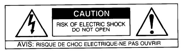
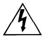
The graphic symbol of a lightning flash with an arrow point within a triangle signifies that there is dangerous voltage within the unit and it poses a hazard to anyone removing the cover to gain access to the interior of the unit Only gualified service personnel should make any such attempt

The graphic symbol of an exclamation point w equilateral triangle warns a user of the device that it is necessary to refer to the instruction manual and its warnings for proper operation of the unit

Do not place this unit on an unstable cart, stand, tripod bracket, or table The unit may fall, causing serious injury to a child or adult, and serious damage to the unit Use only with a cart, stand, tripod, bracket, or table recommended by the manufacturer, or sold with the unit. Any mounting of the device should follow the man ufacturer's instructions, and should use a mounting accessory recommended by the manufacturer
Read all the safety and operating instructions before connecting or using
Retain this notice and the owner's manual for future reference
All warnings on the unit and in its operating instructions should be adhered to
All operating and use instructions should be followed
Do not use this unit near water, for example, near a bathtub, washbowl, kitchen sink, laundry tub, in a wet basement, or near a swimming pool
with its proper ventilation. For example, it should not be situated on a bed sofa, rug, or similar surface that may block the ventilation openings, or placed in a built-in installation, such as bookcase or cabinet, that may impede the flow of air through its ventilation openings
The unit should be situated away from heat sources such as radiators, heat registers, stoves, or other devices (including amplifiers) that produce heat
The unit should be connected to a power-supply outlet only of the voltage and frequency marked on its rear panel
The power-supply cord should be routed so that it is not likely to be walked n or pinched, especially near the plug, convenience receptacles, or where the cord exits from the unit
Clean unit only as recommended in its instruction manual
The power-supply cord of the unit should be unplugged from the wal when it is to be unused for a long period of time
Care should be taken so that objects do not fall, and liquids are not spilled. into the enclosure through any openings
This unit should be serviced by qualified service personnel when
- The power cord or the plug has been damaged, or
- Objects have fallen, or liquid has been spilled, into the unit, The unit has been exposed to rain, or liquids of any kind, or
- The unit does not appear to operate normally, or exhibits a marked change in performance, or
- E The device has been dropped, or the enclosure damaged
DO NOT ATTEMPT SERVICING OF THIS UNIT YOURSELF. REFER SERVICING TO QUALIFIED SERVICE PERSONNEL
ATTENTION
POUR PRÉVENIR LES CHOCS ÉLECTRIQUES NE PAS UTILISER POLABISÉE AVEC UN PROLON CETTE FICHE POLARISEE AVEC UN PROLONGATEUR, UNE PRISE DE COURANT OU UNE AUTRE SORTIE DE COURANT SAUE SU ES LAMES PEUVENT ÊTRE INSÉRÉES A FOND SANS EN LAISSER AU-CUNF PARTIE À DÉCOUVERT
CAUTION
TO PREVENT ELECTRIC SHOCK DO NOT USE THIS POLARIZED PLUG WITH AN EXTENSION CORD, RECEPTACLE OR OTHER OUTLET UN-LESS THE BLADES CAN BE FULLY INSERTED TO PREVENT BLADE
CAUTION
POWER LINES
Any outdoor antenna must be located away from all power lines.
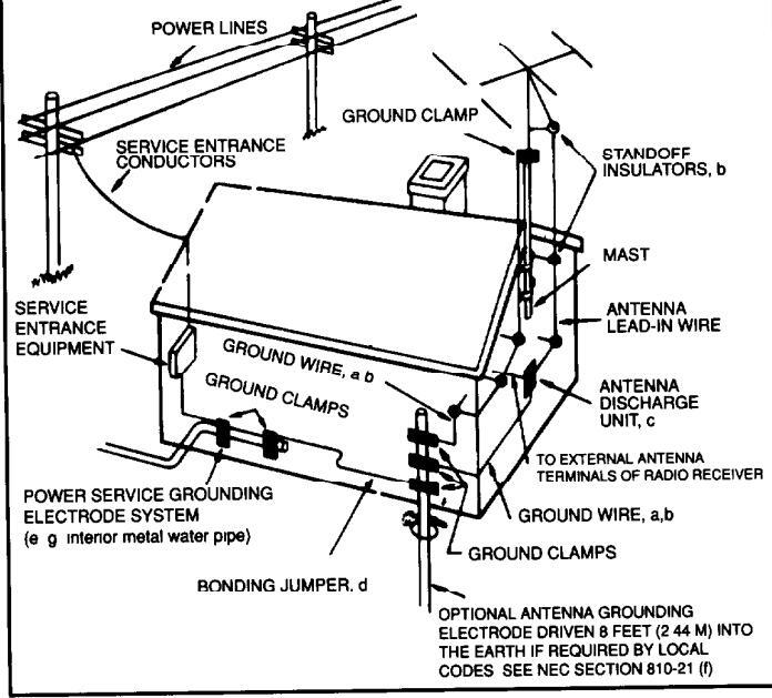
OUTDOOR ANTENNA GROUNDING
If an outside antenna is connected to your tuner or tuner-pream sure the antenna system is grounded so as to provide some protection against voltage surges and built-up static charges. Section 810 of the National Electrical Code. ANSI/NFPA No. 70-1984, provides information with respect to proper grounding of the mast and supporting structure, grounding of the lead-in wire to an antenna discharge unit, size of grounding conductors, location of antenna discharge unit, connection to grounding electrodes, and requirements for the grounding electrode
a Lise No.10 AWG (5.3 mm²) copper. No.8 AWG (8.4 mm²) aluminum. No.17 AWG (1.0 mm2) copper-clad steel or bronze wire, or larger, as a around wire.
b. Secure antenna lead-in and ground wires to house with stand-off insulators spaced from 4-6 feet (1.22-1.83 m) apart.
c. Mount antenna discharge unit as close as possible to where lead-in
d. Use jumper wire not smaller than No 6 AWG (13.3 mm²) cooper. or the equivalent, when a separate antenna-grounding electrode is used. See NEC Section 810-21 (i)
EXAMPLE OF ANTENNA GROUNDING AS PER NATIONAL ELECTRICAL CODE INSTRUCTIONS CONTAINED IN ARTICLE 810 - RADIO AND TELEVISION EQUIPMENT
NOTE TO CATV SYSTEM INSTALLER
This reminder is provided to call the CATV system installer's attention to Article 820-22 of the National Electrical Code that provides guidelines for proper grounding and, in particular, specifies that the cable ground connected to the grounding system of the building, as close to the point of cable entry as practical
INTRODUCTION
FEATURES:
- 100 Watt high-current Center-channel amplifier
- ✓ 50 Watts X 2 high-current Rear-channel amplifiers
- ✓ 2 Audio, 2 Video Inputs. 1 Audio, 1 Video Output
- Full function Remote Control
-
✓ On Screen display for most-used information
- Dolby Pro Logic®, Concert Hall and Night Club soundfields
- Adaptable to Dolby Digital® Surround w/outboard processor
- ✓ 4 independent user-programmable memories
- Bass EQ circuit for more dynamic movie soundtracks
TABLE OF CONTENTS:
| INTRODUCTION |
|---|
| Front Panel Diagram2 |
| Rear Panel Diagram |
| Description of Front Panel Controls4 |
| Description of Rear Panel Controls4 |
| Remote Control Diagram |
| Description of Remote Control Functions |
| INSTALLATION |
| Unpacking8 |
| Placement |
| Which Configuration to Select9 |
| Connection Guidelines9 |
| Connection Diagrams |
| Additional Connections14-15 |
| OPERATION |
| Turning your System On and Off16 |
| Putting the GSA-700 in the Signal Path 16 |
| Saving the Configuration in Memory 17 |
| Setting the Input Levels 17 |
| Setting the Volumes 17 |
| Setting the Subwoofer Volume |
| Choosing a Surround Mode |
| Choosing Delay Times 19 |
| Using the Balance Check 19 |
| Using the On Screen Display 19 |
| MISCELLANEOUS |
| Troubleshooting |
| Servicing |
| Specifications |
DESCRIPTION OF GSA-700:
Congratulations on your purchase of the GSA-700 Surround Amplifier/Processor. You have made a wise choice that will bring you years of entertainment.
The GSA-700 is a unique addition to the Home Theater industry, being a 3-channel, high-current, quality amplifier system combined with a Dolby Pro Logic Processor and including a port to incorporate an Adcom Dolby Digital® Surround Processor (the GDD-1). The GSA-700 is designed to be added to an existing 2-channel audio system to convert it into a 5-channel Audio/Video Home Theater Surround System with the convenience of On Screen display and full-function remote control.
The GSA-700 has 4 independent memories for storing the total configuration, one for each input source. The configuration includes Input Level, Center Volume, Rear Volume, Subwoofer Volume, Surround Mode, and Delay Time. Every time you choose an input source, the configuration changes to your specific needs.
This unit is manufactured under license from Dolby Laboratories Licensing Corporation It is additionally licensed under one or more of the following patents: US number 3,959,590; Canadian numbers 1,004,603, 1,037,877 "Dolby", "Pro Logic", "Dolby Digital" and the double-D symbol (
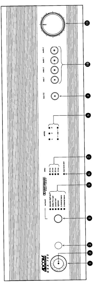
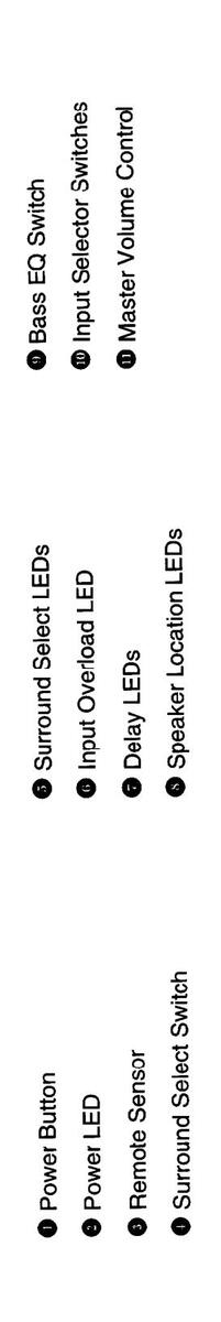
GSA-700 FRONT PANEL DIAGRAM
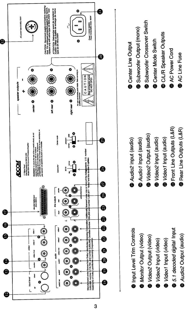
GSA-700 BACK PANEL DIAGRAM
DESCRIPTION OF FRONT PANEL CONTROLS:
-
Power Switch: This momentary-type switch turns the GSA-700 on and off. Depressing the switch gently once A will turn the unit on, depressing it again will turn the unit off. When turning on, there will be a less than 1 second delay before you hear a "click". At this point, the GSA-700 is ready to operate. Power LED: This LED glows red when unit is on and it glows yellow when in standby mode (off). If the LED does 2 not glow at all, then that indicates the unit is not receiving power. Check to make sure it is plugged in and that the AC Line Fuse 🕮 is intact. If both of these conditions are true, then see the "Servicing" section on page 21. A
Remote Sensor
1 This area receives the signal from the remote control. It should be kept clear so the remote control has a clear line of sight to it. Surround Select Button: This momentary button selects the surround mode desired. Depressing the button will 4 advance the sound field to the next one "down" the list. Successively depressing the button will repeat the sequence from top to bottom of the indicated sound fields Surround Select LEDs: These LEDs indicate the current surround mode selected. 5 6 Input Level Alert LED: This LED glows when the input source's signal is too high (loud). If this LED blinks, even slightly, you may hear distortion in your system. When this occurs, the Input Level Trim P needs to be reduced. Delay Select LEDs: These LEDs indicate which delay time is currently selected. Delay Time can be changed A with the Remote Control Delay button I If you are in a surround mode which does not utilize a delay, no LEDs will light Speaker Location LEDs: These LEDs indicate which speakers should be operational in the mode you have 8 chosen. They will also reflect Center-Channel Mode choices with the Center Mode Switch 🕮 on the back panel. When changing the volume of the center or rear speakers, the corresponding LED(s) will blink slowly 6 times. If you have reached the highest or lowest volume obtainable, the LED(s) will blink rapidly many times to indicate that you have reached a limit. Bass EQ: This switch engages the Bass EQ feature. The Bass EQ increases the bass (all frequencies up to 80 9 Hz) by 8dB. It is very useful for extending the "feel" of video soundtracks. Input Selector Switches: These switches select the input source. Also, holding one button down will engage the 10 "save" mode for that input. See "Saving The Configurations In Memory" on page 17. Master Volume Control: This controls the volume level of all speakers and subwoofer(s). The LED in the knob a will glow when the unit is on, and it will blink when you are in the Mute mode (see Mute Button
①
). DESCRIPTION OF BACK PANEL CONTROLS Input Level Trim Control: When the Input Level Alert LED 6 blinks or glows, you may experience distorted P sound (at the peak volumes of the program). By depressing the down button, you will decrease the overall level of that source. By depressing the up button, you will increase the overall input level. (See "Setting the Input Levels" on page 17.) B Video Monitor Output: This output carries the video (picture) plus the On Screen Display information to the TV. Video2 video Output: This carries the video (picture) without the On Screen display information to a video А
- recording device (VCR, etc.). The video signal is determined by which Input Selector Switch 🖤 is pressed.
- Video2 video Input: This jack accepts the video signal from the Video2 source (VCR, LD, etc.).
- Wideo1 video Input : This jack accepts the video signal from Video1 source (DSS, LD, etc.).
- decoded digital input: This DB-25 socket accepts the 5.1 channel signal from the Adcom GDD-1 Dolby Digital adapter. Configurations for this setup are in the GDD-1 owner's manual.
- Audio2 audio Output: These carry the audio Left and Right (sound) to a recording device (Tape, DAT, etc.). The audio signal is determined by which Input Selector Switch ( ) is pressed.
- Audio2 audio Input: These accept the audio Left and Right (sound) from Audio2 source (Tape, etc.).
- Audio1 audio Input: These accept the audio Left and Right (sound) from Audio1 source (CD, etc.).
Video2 audio Output : These carry the audio Left and Right (sound) to a recording device (VCR, Camcorder, etc.). The audio signal is determined by which Input Selector Switch (19) is pressed.
- 22 Video2 audio Input: These accept the audio Left and Right (sound) from Video2 source (VCR, etc.).
- Video1 audio Input: These accept the audio Left and Right (sound) from Video1 source (LD, etc.).
- Front Line Outputs : These jacks carry the Front Left and Right signals to the appropriate Preamplifier input or amplifier input depending on your system configuration. See the "Connection Diagrams" starting on page 10.
- Rear Line Outputs : These jacks carry the rear channel signals to a stereo amplifier. These jacks are used only when bypassing the rear channel amplifiers that are built into the GSA-700.
- Center Line Output: This jack carries the center channel signal to a center channel amplifier. This jack is used only when bypassing the center channel amplifier that is built into the GSA-700.
- Subwoofer Line Output: This jack carries a mono (left and right combined) signal to either a powered subwoofer or an amplifier that drives a non-powered subwoofer. The frequency range of the signal is determined by the setting of the Subwoofer Crossover Switch .
Sy the county of the cashedror of content of content of content of content. Subwoofer Crossover Switch: This switch determines the subwoofer line output frequency content.
120Hz : The subwoofer output carries information from 120Hz and lower at a slope of 12dB per octave. The main outputs are not affected.
80Hz: The subwoofer output carries information from 80Hz and lower at a slope of 12dB per octave.
The main outputs are not affected.
30
Flat: The subwoofer output carries the entire signal. Use this setting with powered subwoofers that have their own built-in crossovers.
Center Mode Switch : This switch allows for a variety of center channel conditions. It will affect line-level ( a) and the speaker-level ( b) outputs.
Wide setting is if your center channel speaker is the same type and size of your front left and right speakers. it sends a full-range signal (all frequencies) to the center channel speaker.
Phantom setting is if you don't have a center channel speaker. It separates the center channel information between the main left and right outputs.
Normal setting is for smaller, more common and esthetic center channel speakers. It removes the bass from the center channel and sends it into the front left and right outputs.

AC Line Cord: This is a detachable cord that is to be plugged into a household AC wall socket or Adcom ACE-515 (see "Turning Your System On and Off" on page 16). Do not plug it into a Receiver or Preamplifier's switched outlet unless that outlet is rated at, or over 600 Watts.
AC Line Fuse: The fuse is accessed by using a large Philips-head screw driver to gently unscrew (counterclockwise) the fuse-cap. It is a 5A, 250 volt MDL-type Slo-Blo fuse. Replace it with ONLY an exact replacement.
NOTES: Video1 should be a non-recording-type video source such as a Laserdisc or Satellite dish. Video2 should be a recording-type video source such as a VCR or Camcorder. Audio1 should be a non-recording-type audio source such as a CD player or Tape Deck. Audio2 should be a recording-type audio source such as a Cassette Deck or DAT machine. (If need be, you can plug an "audio source" into a "video" input such as a CD player into Video1.)
GSA-700 REMOTE CONTROL DIAGRAM
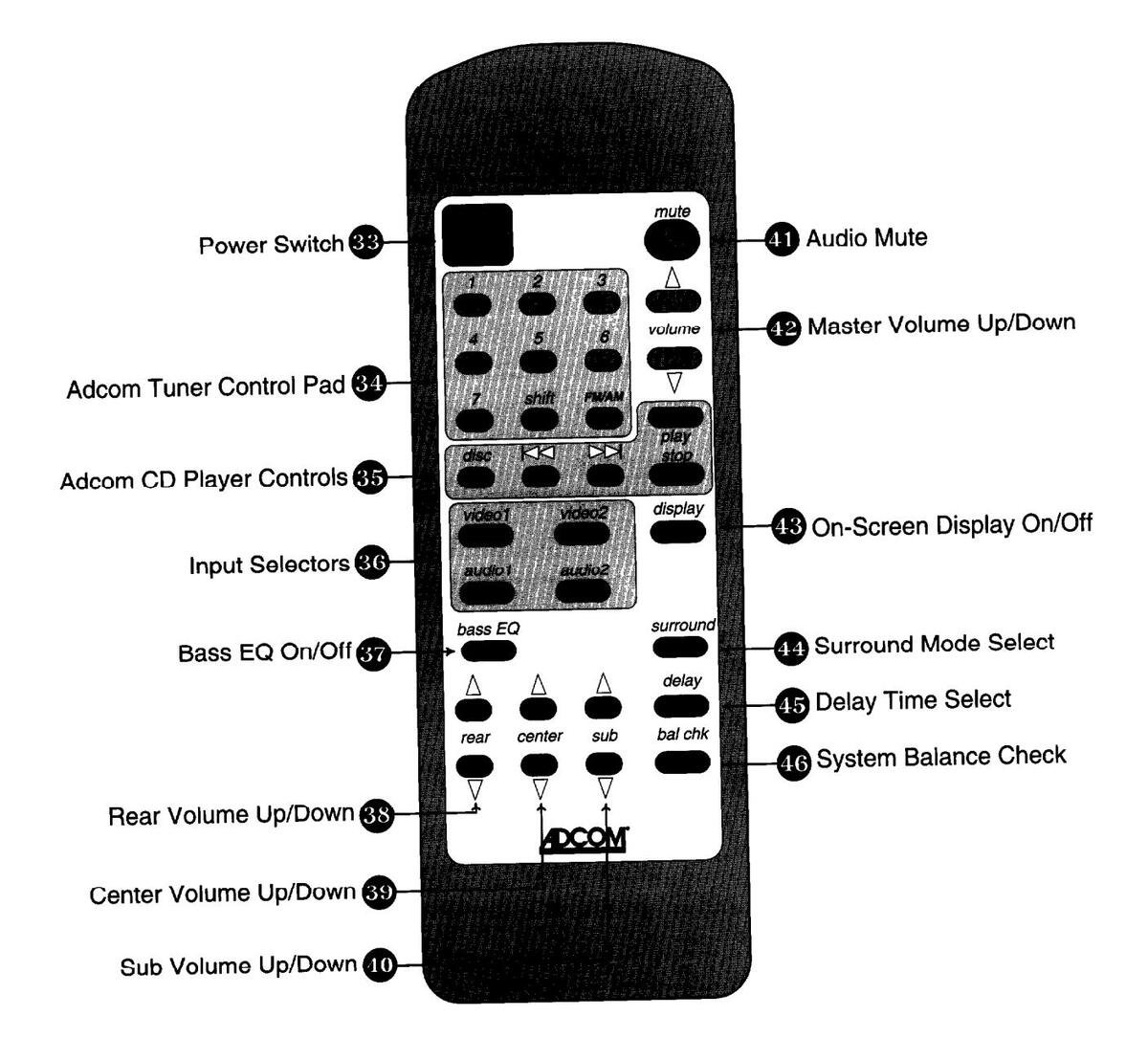
DESCRIPTION OF REMOTE CONTROL FUNCTIONS:
- B Power On/Off: Depressing this switch turns the GSA-700 on, pressing it again will turn the GSA-700 off.
- Adcom Tuner Control Pad: If you own a newer remote-controlled Adcom Tuner/Preamp, this set of buttons will access the tuner presets of that unit. Pressing a numbered button will select that preset station. Pressing the shift button and then a numbered button will access presets # 8 through #14. The FM/AM button toggles between the FM and AM bands.
INSTALLATION
UNPACKING
As part of Adcom's quality control procedure, your GSA-700 was carefully inspected for physical imperfections and electrical performance before it left our building. In the event of physical damage, notify your Adcom dealer immediately and request help in filing a written damage claim.
THE RIGHT TO CLAIM AGAINST A COMMON CARRIER CAN BE FORFEITED IF THE CARRIER IS NOT NOTIFIED PROMPTLY IN WRITING AND IF THE SHIPPING CARTON AND PACKING MATERIALS ARE NOT AVAILABLE FOR INSPECTION. SAVE ALL PACKING MATERIALS UNTIL THE CLAIM HAS BEEN SETTLED. IT IS IMPORTANT TO PLACE ALL THE PACKING MATERIALS INSIDE THE BOX AND TO STORE THE BOX IN A DRY AREA.
PLACEMENT
Since the GSA-700 utilizes high-current amplifiers, it can get warm during normal operation. The chassis has air vents on the top and bottom panels to facilitate the constant flow of air. During prolonged and boisterous operation the GSA-700 could produce significant heat, therefore it is best to follow these guidelines to ensure a long and trouble-free life.
Do not place the unit in an area where heat is produced, such as over a radiator or in front of a heat-vent. Do not place it in an area that can be subject to receiving any amount of moisture and try to avoid extremely dusty areas.
The GSA-700 should be placed in an open environment whenever possible. Since this is usually not practical, an enclosed stereo cabinet is acceptable with a few considerations: At the very least, it is best to have the back of the cabinet open, and if possible, the front as well. If this is not possible, then fans should be integrated into the stereo cabinet to help circulate the air. It is suggested to allow at least 2 inches of air space above the GSA-700 to permit the air to flow freely.
The front panel of the GSA-700 incorporates a remote signal sensor (•) that receives the signal from the remote control. It is advisable that this sensor have a clear line-of-sight to your listening positions. If this remote sensor is obstructed (by side walls of the cabinet or smoked glass doors), you will observe limited (or no) operation from the remote control.
Since the GSA-700 weighs almost 30 pounds, it would be best to place the unit on a sturdy, vibration-free surface. Dropping this unit will likely result in damage.
CONNECTING THE GSA-700 TO YOUR SYSTEM
Whenever connections are being made to any component of your system, make sure all components are turned OFF!
There are 4 primary ways to connect your GSA-700 to your existing stereo system. This text assumes that you either have a preamp and amplifier or a receiver, and at least one "source unit" such as a VCR, laserdisc, or CD player. There are a lot of possibilities for configurations and exceptions for any one of these. We are going to cover most situations and even some of the exceptions. If there are any problems or questions, contact Adcom's Customer Service Dept. (see Servicing on page 21).
If you are bypassing the GSA-700's internal power and using 3 separate channels of power instead, any of these configurations may be used in conjunction with Diagram #5 (see BYPASSING THE INTERNAL POWER)
There should be no reason to connect the main (volume-controlled) output of a preamp to any input on the GSA-700. Putting too much volume to an input can cause damage to the processor and therefore, should be avoided. If you think that your only alternative is to connect the output of the preamp to the input of the GSA-700, please read the instructions on page 9 carefully to avoid damaging the GSA-700. The internal amplifiers of the GSA-700 are designed to work with speakers rated nominally between 4 and 8
The internal amplifiers of the GSA-700 are designed to work with speakers rated nominally between 4 and 6 ohms (Ω). If there is a need to connect more than one speaker to one speaker-terminal, then additional external amplifiers should be used in conjunction with the internal amplifiers, as opposed to connecting 2 speakers to one speaker terminal. As an example, in connecting two center channel speakers, you connect the Center Speaker connector ( Φ ) to one speaker and the Center Line Output ( Φ ) to a mono amplifier connected to the other speaker. If the internal amplifier is overdriven or if the impedance is too low (less than 3Ω) then the amplifier will cut off momentarily and then try to turn back on. If the volume is not reduced, it will continue to cut off. To remedy this situation, reduce the volume for the speaker(s). Check the impedance of the speaker(s) to insure that they are between 4Ω and 8Ω.
Which Configuration to Select:
Configuration #1: SOURCE SELECTOR: If you have 4 or less source units, and you don't plan to take the GSA-700 out of the signal path, use this configuration.
Advantage: Easiest operation, makes a non-remote preamp into a remote preamp, can be used in conjunction with external processors (EQ's, dbx, etc.).
Disadvantage: Processor is always in the signal path.
Configuration #2: TAPE LOOP (PREFERED): If you have a "Tape Monitor" button or switch or a "Record Out" selector on your preamplifier and if you want to be able to take the GSA-700 out of the signal path ( or you have more than 4 source units), this configuration may be used.
Advantage: You can take the GSA-700 out of the signal path, and/or you can connect more than 4 source units. Disadvantage: Slightly more difficult to operate.
Configuration #3: PROCESSOR LOOP (PREFERED): If your preamp has an "external processor" input and output, (some of them have an in/out button on the front panel), you can connect the GSA-700 this way.
Advantage: same as #1 above, plus if you have a front-panel, in/out button, you can take it out of the signal path. This is the ideal configuration.
Disadvantage: If you have no front-panel button, it cannot be taken out of the signal path
Configuration #4: PREAMP: If you choose to use the GSA-700 as a preamplifier itself, you may do so, providing that your main amplifier is rated to deliver between 80 and 200 watts per channel into your speakers (make certain that the wattage rating is matched to the speakers' impedance. i.e. Our GFA-5300 is rated at 80 watts per channel (wpc) into 8Ω, but will deliver 125wpc into 4Ω).
Advantage: Simplest operation and least costly.
Disadvantage: There are no tone, balance, or filter controls to manipulate the sound.
Connection Guidelines:
Configuration #1: SOURCE SELECTOR: If you use this configuration, you will do all of your source (CD, VCR, Tape, etc.) selecting with the GSA-700 source select button (•). You will no longer need to use most of your preamp controls. This is the simplest operation in that you only need to set the preamp's volume and input selector once, and you may never have to touch them again.
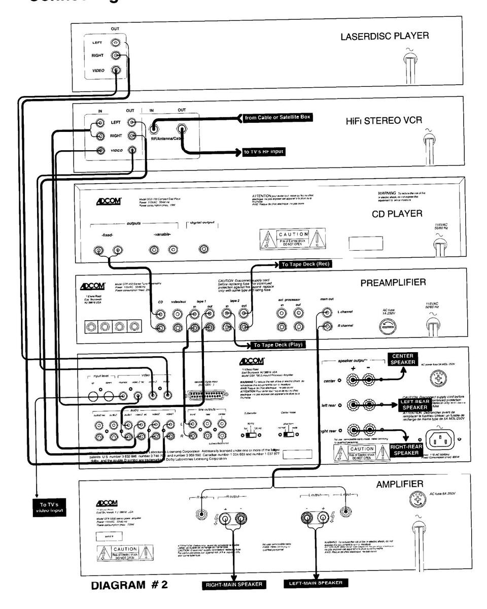
Connections are made as in "Diagram #1" on page 10. If you have a tape deck as well, it can be connected to Audio2 In & Out on the GSA-700. If you own a phonograph, you can either use an external phono preamp and connect it to one of the inputs on the GSA-700, or you can keep it connected to your preamp's phono input but the phono signal cannot get processed by the GSA-700.
Configuration #2: TAPE LOOP: With this configuration, you may keep all or some of your sources connected to your preamp. It is suggested that video-type sources (TV. VCD, etc.) should be connected to the GSA-700 so the video signal can pass through it and "pick up" the On Screen Display on it's way to the TV. This setup enables you to choose whether the GSA-700 is in the signal path or not.
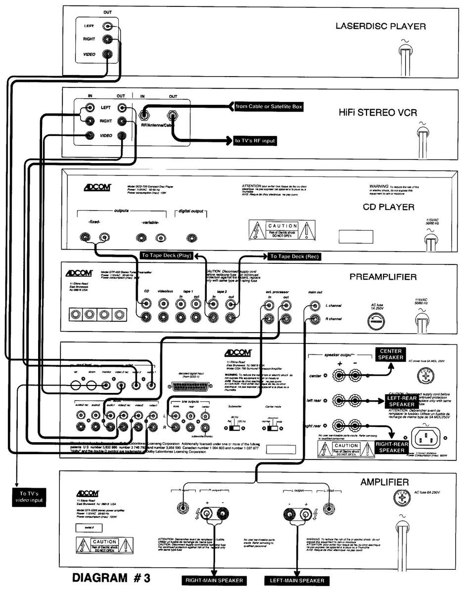
Configuration #3: PROCESSOR LOOP: This configuration has the best of all worlds. Unfortunately, not all preamps come equipped with an external processor button. The connections are according to Diagram #3 and source connections can be made to either the preamp or the GSA-700. As in Configuration #2, it is suggested that video-type sources (TV, VCD, etc.) should be connected to the GSA-700 so the video signal can pass through it and "pick up" the On Screen Display on it's way to the TV.
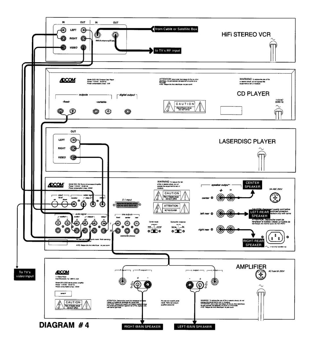
Configuration #4: PREAMP: If you choose to utilize the GSA-700 as the system's preamp, the configuration in Diagram #4 will accomplish this task. There are a maximum of 4 sources that can be connected to the GSA-700. It is suggested that video-type sources (TV, VCD, etc.) should be connected to the GSA-700 so the video signal can pass through it and "pick up" the On Screen Display on it's way to the TV.
If You Have To Connect a Preamp Main Output To an Input on the GSA-700 : Make certain that you do not turn up the preamp's volume control so high that the Overload Indicator LED ( (() ) glows or blinks. If this happen, either turn down the preamp's volume or decrease the input level trim using the buttons on the rear panel ( (() ), (see Setting the Input Levels on page 17).
Connecting The GSA-700 as the primary Source Selector

Connecting the GSA-700 in a Tape Loop (PREFERED)
Connecting the GSA-700 in a Processor Loop (PREFERED)
Connecting the GSA-700 as the Preamplifier
ADDITIONAL CONNECTIONS:
Connecting the Subwoofer
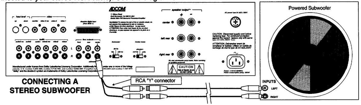
The GSA-700 provides a line-level subwoofer output to be used with either a powered subwoofer, or a passive subwoofer with an external amplifier. If your subwoofer has two inputs (left and right), then simply acquire a highquality RCA "Y" connector with one male end (insert it into the GSA-700's subwoofer out @), and two female ends (connected to your stereo RCA cable). See the diagram below for an illustration on the connection.
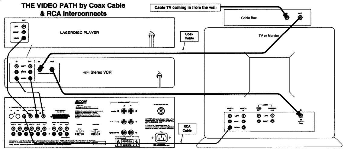
Connecting the Video
A home theater system has 2 parts to it's signal; the audio (sound) and the video (picture) signals. It is very important to "route" the video signal from the sources (VCR, Laserdisc, Satellite receiver, cable box, etc.) through the GSA-700, to the TV. On it's way through the GSA-700 it will "pick up" the On Screen display information. The diagram below shows the signal flow for the 75Ω coaxial cable (carrying the video & audio signals together), and the RCA interconnects (carrying only the video portion of the signal).
The GSA-700 has two video inputs. Video1 is an input for a video-type source, such as a Laserdisc or Satellite receiver. Video2 has an input and an output and should be connected to recording-type video sources, such as a VCR. The GSA-700 has two similar audio inputs. Audio1 is an input for audio-type sources, such as a CD, tuner, or phono preamp. Audio2 has an input and an output and should be used for recording-type audio devices, such as a Tape deck or DAT.
Bypassing the Internal Amplifiers:
Even though the GSA-700 provides you with built-in power for the center and rear speakers, you have the ability to bypass these built-in amps and use other, external amps. Connecting the line-level RCA outputs does not, in any way, affect the speaker level outputs. conversely, connecting the speaker level outputs does not affect the line-level outputs. See diagram #5 for connections to an external amplifier. A GFA-5503 3-channel amplifier is depicted, but any amplifier(s) will work. If you don't have a center channel speaker, you can disregard the center channel outputs and simply connect a 2-channel amplifier for the rear speakers.
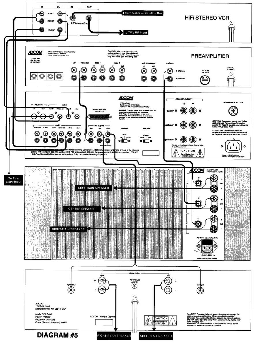
Bypassing the GSA-700's Internal Amplifiers
OPERATION
TURNING YOUR SYSTEM ON AND OFF
There is a proper order in which audio components should be turned on and off. You should be aware of the ramifications of turning your system on and off properly and improperly.
Turn the system ON in this order: 1: All source units. 2: The Preamp (if there is one). 3: The GSA-700 and 4: the Amplifier(s).
Turn the system OFF in this order: 1: The Amplifier(s) (wait for them to totally discharge, up to 30 seconds). 2: The GSA-700 3: the Preamp (if any) and 4: All the sources.
It is normal for any Adcom amplifier to create a small noise a few seconds after turning the unit off. This is the power-supply capacitors discharging and is perfectly normal. Adcom does not put any impeding devices in the signal path, which could affect sound quality, this is why the noise appears at the output. The noise(s) that are created vary greatly from amp to amp and from system to system. There may also be a slight turn-on thump when powering the system up. Turn-on and turn-off thumps will be slightly more pronounced with the GSA-because it employs a basic preamp along with power amplifiers.
If you want to automatically turn the system on and off with one remote control switch, Adcom manufactures a component called the ACE-515. Not only is it a system on-off sequencer, but it also acts as a surge suppressor and an AC-line Enhancer and filter. Since the GSA-700 utilizes a small back-up power supply to maintain it's memory if the power that is supplying the unit is turned off, the GSA-700 can be easily used with an ACE-515 and will retain it's memory for several days before the 4 memories have to be reset. If you are employing an ACE-515, make certain that the GSA-700 is plugged into one of the "Amplifier" outlets. When the system is turned on with the ACE-515, the GSA-700 will go into "standby" mode. The GSA-700 will then need to be turned on with the power switch ( ① ) or the remote power switch ( ① ).
PUTTING THE GSA-700 IN THE SIGNAL PATH
Configuration #1: SOURCE SELECTOR: To operate the system, you will need to choose the input selector on the preamp to which the GSA-700's main outputs are plugged into. For example, in diagram #1, the input selector would be the video/aux , input. The only time it would be necessary to change the input selector is if you want to play another source which is not connected to the GSA-700, such as a turntable. Remember to follow the directions for setting the preamp's volume (see "Setting The Volumes" on page 17).
Configuration #2: TAPE LOOP: There are two ways to put the GSA-700 in the signal path. In both cases, the Input selector on the GSA-700 ( • ) should be set to audio1 .
The first way to insert the GSA-700 is if you have a "Tape Monitor" button or switch on your preamp. If this is the case, simply press or select the Tape Monitor button or switch. If the source that you want to listen to is connected to the GSA-700, then simply choose that source on the Input Selector of the GSA-700 ( @ ). When the GSA-700 is in the signal path, simply follow the directions for setting the preamp's volume (see "Setting The Volumes" on page 17).
Signal pain, simply follow the directions for setting the preamp's volume (see "Setting The volumes" on page 17). The second way to incorporate the GSA-700 is if you have a "Record Output" selector. Simply set your Input selector to "Tape 1" and set your Record Out selector to the source you want to listen to. If the source you wish to play is connected to the GSA-700 and not the preamp, then it doesn't matter where the Record Out selector is set as long as the Input selector on the preamp is set to Tape 1, then you simply choose the appropriate input on the Input Selector of the GSA-700 ( ① ). When the GSA-700 is in the signal path, simply follow the directions for setting the preamp's volume (see "Setting The Volumes" on page 17).
Configuration #3: PROCESSOR LOOP: To put the GSA-700 into the signal path, simply press the "processor" button to the in position. If there is no processor button, there will be a pair of RCA connections on the back panel with metal jumpers inserted in them, Simply remove the jumpers and connect the GSA-700 as in diagram #3. This way, the GSA-700 will always be in the signal path. When the GSA-700 is in the signal path, follow the directions for setting the preamp's volume (see "Setting The Volumes" on page 17).
Configuration #4: PREAMP: The operation is similar to Configuration #1, except that you have no "preamp volume" to set. The center and rear volumes will be relative to the volume of the main left and right speakers. You cannot vary the volume of the main left and right separately from the rest of the system. As long as your main amplifier is similar in power to the center channel power, this presents no problems. Providing that the front 3 speakers are of equal impedance, it is recommended that the Main amplifier be between 80 and 200 watts per channel (into 80).
SAVING THE CONFIGURATIONS IN MEMORY
The GSA-700 can remember the settings of Input Level, Center Volume, Rear Volume, Sub Volume, Surround Mode and Delay Time for each of the four individual inputs. The levels and settings of these 6 parameters are know as a configuration . Every time that you choose a new input source by using the Input Selector switches on the front panel ( () ) or the remote control ( () ), it will recall the specific configuration that was previously saved.
To save a configuration, select an input source. Then you will need to choose the settings for: Input Level, Center Volume, Rear Volume, Sub Volume, Surround Mode and Delay Time as described in the next few sections. Once you have chosen the settings that will most likely be used with the source chosen, you have the GSA-700 remember the settings by pressing and holding the Input Selector (either front panel or remote control buttons). The LED in that button will blink 3 times and the input source indicator in the On Screen display will blink 3 times. When they have blinked 3 full times , the configuration is saved.
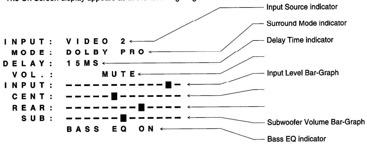
Here is an example of a setting for video2 which has a Laserdisc connected to it. Input level is down by 1 (segment on the On Screen display), center volume is -1, rear volume is +2, sub volume is 0 (center segment in bar graph), surround mode is Dolby Pro Logic and delay time is 15ms. now every time that you choose video2 this configuration will be recalled. The On Screen display diagram in the "Using the On Screen Display" section shows this very configuration.
All inputs that have sources connected to them should have corresponding configurations set to memory. If you choose a new configuration and then repeat the "saving" process, it will replace the old memory with the new settings.
SETTING THE INPUT LEVELS
Occasionally, a source unit may deliver higher voltages (louder volumes) than the input of the Dolby Pro Logic decoder circuit can safely handle. When this happens you will see the Input Level Alert LED ( ① ) blink, and hear distortion (a crackling or "breaking up") when louder sounds occur. This is detrimental to the Pro Logic decoder circuit and should be avoided. To remedy this situation, we have incorporated an Input Level Trim on the rear panel ( ④ ). It is possible to "trim" the input level on each input individually so that trimming one source (i.e. VCR) does not effect another source (i.e. CD). You may also trim an input source to "match" the sources so that they have equal volumes when you switch among them. For example, if your tape deck has the lowest volume, you may trim all the other setting to the same level as the tape deck.
To trim an input, select the source with the Input Selector Switch ( • ) or remote buttons ( • ). You may either reduce it by ear or by using the On Screen Display. To set the level by ear, make sure you have a very loud program on. If you are setting the VCR, choose a movie with explosions or gunshots. Simply press the "-" Input Level Control ( • ) until the distortion stops and the Input Level Alert LED ( • ) stops blinking. The best method is to press the "-" button once, then check the LED for a few minutes. If it blinks at all, press the "-" button again. Repeat this procedure until the input level alert LED does not blink at all.
To set the input levels by using the On Screen display, make sure that your TV is on and set to the proper input mode (video 1 or similar). On the GSA-700's remote control, turn on the On Screen display by pressing the Display button ( @ ). You can be in any surround mode except Dolby Digital, although we suggest using the surround mode that will be used most with that input source (i.e. Dolby Pro Logic for Video1). Each time that you press the "-" Input Level Control ( @ ) button, the indicator square (on the "Input Bar-Graph") will move to the left. Each time you press the "+" Input Level Control ( @ ) button, the indicator square will move to the right. Set all the input levels the same way as described above.
SETTING THE VOLUMES
If you are adding the GSA-700 to an existing system, you will notice that you now have two volume controls. The overall system volume control will be handled by the GSA-700 volume control ( ① ), while the preamp's volume control will effect only the left and right main speakers. This section will explain how to set the volume of the whole system and when the functions of each volume control changes.
To set the preamp volume, follow this procedure: 1: On Surround Select ( ① on the remote), choose Dolby Pro Logic. 2: Turn the GSA-700 volume to a comfortable level and the preamp's volume to off. 3: Press the On Screen Display button ( ④ ) and adjust the center and rear volumes using the controls on the remote ( ⑤ and ⑥ ) to approximately center. 4: Use the Balance Check feature to set the relative volume levels (see "Using The Balance Check" on page 19. 5: Slowly turn up the preamp's volume until the Left and Right main speakers are approximately the same volume as the center channel.
The preamp's volume control is now set to the GSA-700. As long as the GSA-700 Is in the signal path, you will operate the GSA-700 volume control ( 0 ) as the "system" volume. You should not have to touch the preamp's volume
control except for fine tuning the system. If, however, you take the GSA-700 out of the signal path, be sure to reduce the preamp's volume level before you do.
Once the system volumes are set, IT WILL NOT BE UNUSUAL TO TURN THE GSA-700'S VOLUME CONTROL WELL PAST HALF-WAY TO ACHIEVE ADEQUATE LISTENING VOLUMES . Since everything is relative to the volume setting on the preamp , half-volume on the GSA-700 is actually half of the volume of where the preamp is set. Once the system is completely balanced, it is suggested to mark the preamp's volume level so that it can be easily accessed again at any time.
SETTING THE SUBWOOFER'S VOLUME
Most self-powered subwoofers that are available today have their own volume controls. If this is the case in your subwoofer, follow this simple procedure to properly set the volume control on the subwoofer to your system.
First, choose a source and some program material which might be an average representation of your listening style. We recommend something that has a significant bass content such as a movie with a lot of action or a dynamic soundtrack. Turn your whole system on (including the subwoofer), and start the movie (or CD, etc.). Make sure that your subwoofer level is set at mid-point by pressing the Display button ( ① ) on the remote control. Turn up the Master volume ( ① or ① ) to an average, or above-average listening level. Go to your subwoofer and set the volume to what seems to be a similar level. Sit in your listening position and try to discern whether the bass content seems too loud of too soft (sometimes the bass will increase or decrease when you move from spot to spot in a room). If it is too loud or soft, re-adjust the subwoofer's volume control. Once you have an acceptable level set on the subwoofer's volume control, it is then resolved and should not have to be touched again (unless the subwoofer is re-positioned). You can now increase or decrease the subwoofer level with the Sub Volume Up/Down controls ( ① ) on the remote control from your listening position.
CHOOSING A SURROUND MODE
The GSA-700 offers 6 soundfields for listening to your program material. That material will dictate which soundfield is best to listen to, with the exception of Dolby Digital and Dolby Pro Logic, all other selections are suggestions. Selecting the surround mode is done with either the Surround Select switch ( ① ) on the front panel or the Surround Select button ( ① ) on the remote control. Pressing either button once will advance the mode to the next one "down" the list. There is a red LED next to the currently selected mode, or you can see the selected mode on the On Screen display in the Input Select indicator section. Here is a comprehensive summary of each soundfield.
Dolby Pro Logic: In this mode, the GSA-700 presents a spatially correct soundstage with precise lateral imaging and front to back depth. It is to be used only when you have a Dolby Surround signal. To determine if you have a Dolby Surround signal, you can check for a Dolby Surround logo on the box. You may also select Dolby Pro Logic mode and listen to the system. If almost all the sound is coming from the center channel speaker, then you do not have a Dolby Surround signal, and you should choose any of the other surround modes to listen to. Some TV stations now transmit their signal in surround (there is usually a "surround" logo at the beginning of the show). and most cable companies offer stereo transmission with their service, enabling all premium channels (HBO, Cinemax, etc.) to be enjoyed in surround. You do, however, need a stereo (or MTS) VCR or TV to receive these signals. There is an increase in the amount of shows transmitted in surround, including sitcoms and most notably, sporting events.
Concert Hall: This mode recreates a fairly large environment such as a music hall or church. Front channel frequency response is kept flat for musical clarity while diminishing multiple delays are added to the rear to enhance the sense of spaciousness. The center channel speaker continues to work to fill in the front soundfield. Both stereo and mono sources can be used with this mode. Live recordings, orchestral work and any music that is performed in large indoor spaces are optimized by this mode. You may also find that sporting events sound more realistic in this mode.
Night Club: This mode synthesizes a smaller, warmer and more personal soundfield. Front channel highfrequency information is slightly equalized for a warm, intimate front soundstage, and the rear channels contain only the single delay selected. During Night Club operation the center channel speaker is switched off to retain front stage imaging. This mode is ideal for many types of jazz and popular music. TV programs that are transmitted in stereo or mono, yet are not surround, also sound full and true with this mode.
5-Channel Stereo: This mode makes full use of the home theater's speaker compliment without adding any processing or delay. This is the only mode where the rear speakers operate in stereo (as opposed to mono). The center channel speaker will produce a mono (L+R) signal, while the left-rear speaker will reproduce the left signal and the right-rear speaker will reproduce the right signal. By adjusting the center and rear volumes, you can create a dynamic and complete soundfield without the slight blurring effect of a delay line. There is no delay time to choose in this mode.
2-Channel Stereo: This is also considered "Bypass" mode. The center and rear speakers are turned off, and the signal is passed through the GSA-700 with no alteration. There is no delay time to choose in this mode.
CHOOSING A DELAY TIME
In addition to adding a sense of spaciousness and ambiance, rear channel time delay serves a specific purpose in Dolby Pro Logic playback. It prevents us from hearing front channel information, particularly dialog, from the rear speakers. Based on a psychoacoustical effect called "masking", this technique preserves the proper directional clues intended by the source's producer.
Longer delay periods defeat the "masking" effect and create awareness of a growing discontinuity between the front and rear outputs. Eventually, the rear channel output becomes a discrete echo rather than an integral part of a coherent soundfield. For this reason, Dolby Pro Logic intentionally limits rear channel time delay to relatively small amounts.
USING THE BALANCE CHECK
In the Dolby Pro Logic mode, it is important to match the volume settings on all the speakers so that they are as close as possible. This measurement is usually done with your ears and is an accepted practice, however some people prefer to use a hand held SPL (sound pressure level) meter for matching levels.
To use the System Balance Check, you must be in Dolby Pro Logic mode and it is recommended that no source be playing at the time. If you are not in Dolby Pro Logic mode when you run through the Balance Check, the GSA-700 will automatically revert to Pro Logic mode when the Balanced Check is done. The optimum manner to set the volume level is to utilize the remote control and sit in the primary listening position. Press the Bal Chk button ( ① ) on the remote. You will notice a "waterfall" type sound emanating from the front-left speaker. It will last until you press the button again, then it will move to the center speaker. Successively pressing of the button will advance the waterfall noise to the front-right speaker, then the two rear speakers at the same time. After the rear speakers, pressing the button again will deactivate the noise. By listening to the relative loudness of each speaker, you may adjust the independent volumes for the center and the rear speakers relative to the front left and right speakers , by using the Rear Volume Up/Down ( ④ ) and Center Volume Up/Down ( ④ ) on the front panel will blink slowly many times to indicate the change. If you have reached the upper or lower limits of the volume range, the LED(s) will blink 3 times rapidly.
If you have to turn the center or rear channels up to full-on and they aren't loud enough, you will need to reduce the preamp's volume as stated in "Setting the Volumes" on page 17. Similarly, if the center or rears are too overpowering, try bringing the preamp's volume up. Ideally, similar volumes should be achieved while the center and rear indicators on the On Screen display are in (or near) the middle of the bar-graph. Repeat the process of setting the levels until the ideal balance is achieved. Once the system is balanced, it is suggested to mark the preamp's volume level so that it can be easily accessed again at any time.
USING THE ON SCREEN DISPLAY
When the GSA-700 is properly configured and wired to your video monitor (TV), you have the ability to set relative levels and check all the functions of the unit by utilizing the On Screen display function. This gives you a complete visual indication of the status of the GSA-700.
By pressing the Display button ( (() ) on the remote control, you can activate the On Screen display function. The display will replace whatever was on the screen previously. By pressing the Display button ( (() ) again, it will turn this function off and return your previous screen to view.
Whenever the Master Volume ( 0 or @ ) is changed, the Volume Up/Down indicator will reveal that change. Whenever an input is changed with the Input Selector ( 0 or 0 ), the Input Source indicator will reveal which input was
selected. If the source that is selected happens to have an excessive output signal, the Input Level Alert indicator will blink. This is an indication that the input source needs to be trimmed (see "Setting The Input Levels" on page 17).
The MODE and DELAY sections will indicate which surround mode is selected and what the delay time is. The LEVEL section will show the word MUTE when the system is muted via the Audio Mute button ( 0 ) on the remote control. The bottom line will indicated whether the Bass EQ has been activated via the Bass EQ switch ( 0 or 9 ).
The Bar-Graphs (series of boxes) to the right of the labels: INPUT, CENT, REAR, and SUB. are used to gauge the relative volume of each output. When the indicator box is in the middle (as shown in the SUB section, below), this indicates that the volume of that specific output is in the middle (this is also the default setting). The volume can be adjusted Up or Down from this mid-point. When doing a Balance Check, the CENT and REAR should be started at this point, and depending on your system, should be adjusted so that they remain close to center (see "Using the Balance Check" on page 19.

TROUBLESHOOTING
Use the chart on the next page to solve common situations that don't require professional attention. If the steps stated in POSSIBLE SOLUTION do not resolve your problem, then please contact your Adcom Dealer or call the Adcom Customer Service Department. Any problems not covered here should be brought to the attention of your Adcom Dealer or Adcom Customer Service Department.
When there is a low-volume "hum" audible throughout your speakers, even with the main volume turned all the way down, you have a common phenomenon known as a "ground loop". A ground loop is basically a difference in ground voltages between two or more components which are connected electrically and which creates multiple current paths where there must only be one. This difference in potential creates a 60Hz low-level sound (approximately a low A#), that appears to "hum", hence the name.
It can be caused by adding new components to your system, but that does not imply there is anything electrically wrong with any new component. With the advent of audio/video and home theater systems, the problem has become commonplace. Generally, the cause is the Cable-TV incoming signal line. This new incoming line may add an additional ground at a different potential from the AC line ground of your other equipment.
CAUTION: When connecting or disconnecting ANY cables, always be sure that your system has been turned OFF!
Note 1: Cable TV systems can sometimes contribute to ground-loop problems which cause "hum". To determine if your cable system is the contributing factor, disconnect the Cable-TV incoming signal line (round, 75Ω) at the wall, or the first component to which the cable is connected (i.e. the cable box, or VCR). If the hum is no longer present, you must insert a "75Ω Ground Loop Isolator" before reconnecting the line. You should check with your Adcom Dealer to obtain one. If the "75Ω Ground Loop Isolator" works only partially or not at all, then please read Note 2 to complete the troubleshooting procedure.
complete the troubleshooting procedure. Note: Disconnect all RCA connections from the GSA-700. If the hum still persists, then your Dealer or Service Center must examine the unit. If the hum disappears, try another set of RCA cables. Connect one RCA cable at a time to see if one specific cable or component is responsible. Be sure to connect both ends of the RCA cables; one to the GSA-700 and the other to it's destination. If any or all cables cause the hum to appear, try replacing the RCA cables. It that fails to solve the problem, then the preamp or processor or other components should be evaluated for proper operation by your Authorized Dealer, Authorized Service Center, or Adcom Service Department.
| SYMPTOM | POSSIBLE REASON | POSSIBLE SOLUTION |
|---|---|---|
| Power LED ( ) does not | AC Power Cord( ) not plugged in. | Plug in AC Power Cord( ). |
| glow. No sound | AC Fuse() blown. | Replace AC Fuse(. |
| - | Transformer thermal protection engaged | Bring to Dealer or Service Center. |
| In Pro Logic mode, all | You don't have a Pro Logic-encoded | Ensure that you have a Dolby Surround |
| the sound comes from | signal. | encoded signal. |
| the center speaker | The Pro Logic signal is being modified by a | Connect the video source directly to a |
| component that it passes through (EQ, TV) | video input on the GSA-700. | |
| Either center or rear | Speaker connectors disconnected or loose. | Verify connections on that channel. |
| channel not producing | Speaker disconnected. | Verify connection at speaker. |
| any sound | Internal protection engaged | Bring to Dealer or Service Center. |
| No output from the Main | The GSA-700 is not "sending" the signal to | Verify RCA connections from Front Line |
| left and right speakers | the preamp. | Lett & Right outputs ( ) to preamp. |
| Preamp is not "receiving" the signal from | Wiring correct? Read "Putting the GSA- | |
| the GSA-700 | 700 in the Signal Path" on page 16. | |
| Preamp is not "passing" the signal through. | Make sure preamp passes a signal. | |
| Main amplifier is not on, or working. | Make sure amp is on & works properly. | |
| Center or Rears cutting | Internal amps being overdriven | Volume too loud, turn it down. |
| in and out | Speaker impedence too low | Check speaker impedence, or if multiple |
| speakers are on one channel, remove | ||
| one to bring total to above 4Ω. | ||
| Distorted sound on | Source unit has excessive output volume. | Heduce the input level on that source |
| louder passages | ||
| Erratic operation or all | Digital lockup of the microprocessor. | Unplug the unit and let it sit for 1/2 an |
| operations "freeze up". | nour. Mug it back in and resume | |
| Hum from all speakers | Ground loop (difference in ground voltages | |
| at any volume |
| paye 20).
| If Cable TV is not present (see Note 2 on |
|
| nage 20) | ||
| Como major appliance, dimmor, hologon er | Make sure all appliances dimmers and | |
| Hum from the GSA-700 |
Some major appliance, ultimer, halogen of
fluorescent light is creating interference |
suspect lights are off, or on a different |
| lisen | circuit of the house. | |
SERVICING
ADCOM has a Technical Service Department to answer questions pertinent to the installation and operation of your unit. In the event of difficulty, or if any of the POSSIBLE SOLUTIONS in the Troubleshooting section above fail to solve your problem, please call for technical assistance. For fax inquires, please include a return fax or voice number for the reply. When calling or writing about your
For fax inquires, please include a return fax or voice number for the reply. When calling or writing about your GSA-700, be sure to note and refer to its serial number as well as the date of purchase and the dealer from whom it was purchased. In the event the unit must be returned to our factory for service, you will be instructed on the proper procedure when you call or write for a Return Authorization. For warranty coverage, a copy of the original proof of purchase is required. If you have no original copy, please contact your dealer to obtain a duplicate copy.
If the original shipping carton and its fillers have been lost, discarded, or damaged, a duplicate carton may be obtained from our Service Department for a nominal charge.
Always ship PREPAID VIA UNITED PARCEL SERVICE (UPS) OR OTHER APPROVED CARRIER. DO NOT SHIP VIA PARCEL POST, since the packing was not designed to withstand rough Parcel Post handling. FREIGHT COLLECT SHIPMENTS CAN NOT BE ACCEPTED UNDER ANY CIRCUMSTANCES.
UNDER NO CIRCUMSTANCES SHOULD YOUR UNIT BE SHIPPED TO OUR FACTORY WITHOUT PRIOR AUTHORIZATION, OR PACKED IN OTHER THAN ITS ORIGINAL CARTON AND FILLERS.
GSA-700 SPECIFICATIONS
AMPLIFIER SECTIONS
Power Rating (To FTC Requirements)
100 watts continuous average power into 8 ohms at any frequency: 20Hz to 20kHz with all channels driven at less than 0.05% THD for the Center Channel 50 watts continuous average power into 8 ohms (X 2) at any frequency: 20Hz to 20kHz with all channels driven at less
50 watts continuous average power into 8 ohms (X 2) at any frequency: 20Hz to 20kHz with all channels driven at less than 0.05% THD for the Rear Channels
| IM Distortion | |
|---|---|
| (SMPTE) 1 watt to rated power into 8 ohms | ≤ 0.02% |
| (CCIF, from 4kHz to 20kHz) Rated power into 8 ohms | ≤ 0.07% |
| Frequency Response @ 1 watt into 8 ohms (10Hz to 20kHz) | +0, -0.5dB |
| Signal to Noise Ratio, "A" Weighted | |
| 100 watts into 8 ohms (Center) | ≥ 104dB |
| 50 watts into 8 ohms (Bears) | ≥ 104dB |
2-CHANNEL STEREO MODE (Line outputs)
| Frequency Response (20Hz to 20kHz) | +0, -0.5dB |
|---|---|
| THD+N (20Hz to 20kHz) | ≤ 0.025% |
| IM Distortion | |
| SMPTE | ≤ 0.05% |
| CCIF, from 4kHz to 20kHz | ≤ 0.05% |
| Signal to Noise Ratio, "A" Weighted (ref. To 1 volt) | ≥ 97dB |
DOLBY PRO LOGIC© MODE (Line outputs)
| Left, Center and Right Channels | |
|---|---|
| Frequency Response [center in wide mode] (20Hz to 20kHz) |
+0, -0.5dB |
| THD+N (100Hz to 20kHz) |
≤ 0.05% |
| Signal to Noise Ratio, "A" Weighted (ref. To 1 volt) |
≥ 86dB |
| Hear Channels | |
|---|---|
| Frequency Response (20Hz to 7kHz) | .+0, -3dB |
| THD+N (1kHz) | ≤ 0.35% |
| Signal to Noise Ratio, "A" Weighted (ref. To 1 volt) | . ≥ 86dB |
GENERAL
| Power (Available in 230VAC on special order) | 115VAC - 50/60Hz |
|---|---|
| Power Consumption (Continuous, Both Channels Driven) | |
| Quiescent | |
| Maximum | |
| Dimensions | |
| Chassis . | 41/8" (124mm) x 17" (432mm) x 121/8" (327mm) |
| Maximum Dimensions | 5" (127mm) x 17" (432mm) x 14¼" (362mm) |
| Weight | |
| Unpacked | |
| Packed |
Please address mail inquiries to: ADCOM Service Corporation 11 Elkins Road East Brunswick, NJ 08816 U.S.A.
Phone or Fax inquiries to: Voice: (908) 390-1130 or (732) Fax: (908) 390-9152 or (732) Monday through Friday 9:00 AM to 5:00 PM EST
© / DCOM 1996


 Loading...