

ADCOM TUNER GFT-5555
THE FOLLOWING PRECAUTIONS AND SAFETY INSTRUCTIONS ARE REQUIREMENTS OF UL AND CSA SAFETY REGULATIONS
Warning: To reduce the risk of fire or electric shock, do not expose this unit to rain or moisture.
The graphic symbol of a lightning flash with an arrow point within a triangle signifies that there is dangerous voltage within the unit and it poses a hazard to anyone removing the cover to gain access to the interior of the unit.Only qualified service personnel should make any such attempt.
The graphic symbol of an exclamation point within an equilateral triangle warns a user of the device that it is necessary to refer to the instruction manual and its warnings for proper operation of the unit.

Do not place this unit on an unstable cart stand tripod bracket, or table. The unit may fall, causing serious injury to a child or adult, and serious damage to the unit. Use only with a cart, stand, tripod, bracket, or table recommended by the manufacturer, or sold with the unit Any mounting of the device should follow the man-
ufacturer's instructions, and should use a mounting accessory recommended by the manufacturer.
Retain this notice and the owner's manual for future reference
All warnings on the unit and in its operating instructions should be adhered to.
All operating and use instructions should be followed
Do not use this unit near water; for example, near a bathtub, washbowl, kitchen sink, laundry tub, In a wet basement, or near a swimming pool.
The unit should be installed so that its location or position does not interfere with its proper ventilation. For example, it should not be situated on a bed sofa, rug, or similar surface that may block the ventilation openings; or placed in a built-in installation such as bookcase or cabinet, that may impede the flow of air through its ventilation openings.
The unit should be situated away from heat sources such as radiators, heat rs, stoves, or other devices (including amplifiers) that produce heat
The unit should be connected to a nower-supply outlet only of the voltage and frequency marked on its rear panel.
The power-supply cord should be routed so that it is not likely to be walked on or pinched, especially near the plug, convenience receptacles, or where the cord exits from the unit.
Clean unit only as recommended in its instruction manual.
The power-supply cord of the unit should be unplugged from the wall outlet when it is to be unused for a long period of time.
Care should be taken so that objects do not fall, and liquids are not spilled,
This unit should be serviced by qualified service personnel when: The power cord or the plug has been damaged; or
- B. Objects have fallen, or liquid has been spilled, into the unit; or
- The unit does not appear to operate normally, or exhibits a
- marked change in performance: or The device has been dropped, or the enclosure damaged
DO NOT ATTEMPT SERVICING OF THIS UNIT YOUR REFER SERVICING TO QUALIFIED SERVICE PERSONNEL.
ATTENTION
POUR PRÉVÉNIR LES CHOCS ÉLECTRIQUES NE PAS UTILISER CETTE FICHE POLARISÉE AVEC UN PROLONGATEUR, UNE PRISE DE COURANT OU UNE AUTRE SORTIE DE COURANT, SAUF SI LES LAMES PEUVENT ÉTRE INSÉRÉES À FOND SANS EN LAISSER AU-CUNE PARTIE À DÉCOUVERT
CAUTION
TO PREVENT ELECTRIC SHOCK DO NOT USE THIS POLAHIZED PLUG IN PREVENT ELECTRIC SHOCK DO NOT USE THIS POLARIZED PLUG WITH AN EXTENSION CORD, RECEPTACLE OR OTHER OUTLET UN-LESS THE BLADES CAN BE FULLY INSERTED TO PREVENT PLADE
POWER LINES
Any outdoor antenna must be located away from all power lines
OUTDOOR ANTENNA GROUNDING
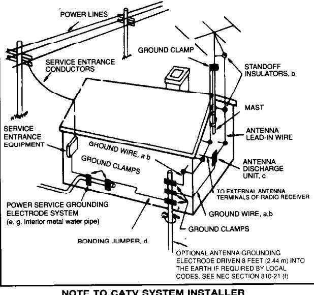
If an outside antenna is connected to your tuner or tuner-preamplifier, be sure the antenna system is grounded so as to provide some protection against voltage surges and built-up static charges. Section 810 of the al Electrical Code, ANSI/NEPA No. 70-1984, provides information with respect to proper grounding of the mast and supporting structure, grounding of the lead-in wire to an antenna discharge unit, size of grounding conductors, location of antenna discharge unit, connection to grounding electrodes, and requirements for the grounding electrode
a. Use No.10 AWG (5.3 mm²) copper. No.8 AWG (8.4 mm²) aluminum No.17 AWG (1.0 mm2) copper-clad steel or bronze wire or larger, as a around wire
ure antenna lead-in and ground wires to house with stand-off insulators spaced from 4-6 feet (1.22-1.83 m) apart.
c. Mount antenna discharge unit as close as possible to where lead-in
d. Lise jumper wire not smaller than No 6 AWG (13.3 mm²) copper, or t equivalent, when a separate antenna-grounding electrode is used. See NEC Section 810-21 (i).
EXAMPLE OF ANTENNA GROUNDING AS PER NATIONAL ELECTRICAL CODE INSTRUCTIONS
This reminder is provided to call the CATV system installer's attention to This reminder is provided to call the CATV system installer's attention to Article 820-22 of the National Electrical Code that provides guidelines for proper grounding and, in particular, specifies that the cable ground shall be connected to the grounding system of the buildina, as close to the point of cable entry as practical.
Features
The design of the GFT-555II, based on that of its predecessor the GFT-555, incorporates many improvements which not only enhance its performance capabilities but insure that these are maintained when interconnected into an audio system. Among these are:
- New extra-low-impedance output (100-ohms) for minimal interaction with interconnecting cables and preamplifiers.
- Buffered outputs using high-speed linear amplifiers with extremely low distortion based on the design of the GFP-555II, to insure optimal operation of the multiplex circuitry without "loading" by any external connections to the tuner.
- Switch-adjustable output with a three-position switch providing 0.5 volt, 1.0 volt and 2.0 volt output level for complete compatibility with all preamps, passive control devices (such as ADCOM's SLC-505) and matching to line levels of all cassette recorders, CD players, etc.
- All 1% Roederstein metal-film resistors and high-grade metallized film capacitors in audio circuits and critical tuner functions.
- Improved IF circuitry with more symmetrical skirts and newly selected ceramic filters.
- Improved AM tuner with flatter frequency response and reduced distortion.
- Low-loss PC board for minimal signal degradation.
- Improved RF circuitry with better image rejection and lower noise.
- May be remotely controlled when interfaced with ADCOM GFB-800 Remote Control System.
IMPORTANT NOTICE
ADCOM PROTECTION PLAN (U.S.A. ONLY)
ADCOM offers the enclosed valuable LIMITED WARRANTY. Please read the details on the Warranty Card carefully to fully understand the extent of the protection offered by the Warranty, its reasonable limitations, and what you should do in order to obtain its benefits.
Be sure to verify that the serial number printed on the back panel matches the serial number on the outer carton. If either number is altered or missing, or if the Warranty Card is not included in the carton, you should notify us immediately in order to insure that you have received a genuine ADCOM product which has not been opened, mishandled or tampered with in any way.
INTRODUCTION
Please read thoroughly the operating instructions for the GFT-555II before connecting or attempting to operate this unit. For your own benefit, follow all the instructions in this manual and save it for future reference.
The ADCOM GFT-555II is the result of a thorough examination of all factors affecting the sonic performance of FM tuners. A great deal of effort was expended in insuring that the audio performance of the GFT-555II would not be degraded by employing often compromising methods of "improving" measured RF specifications. The result is a tuner which is as musical-sounding as any, and with audio performance which is superior to the signal transmitted by more than 99% of the FM stations broadcasting in the U.S.A.
The installation and operation of the GFT-555II are described in the following pages. We sincerely hope you will value and enjoy the considerable attention we have given its design and construction. This manual, and your familiarity with it, are essential to understand the correct operation of the GFT-555II. Please read it carefully to fully comprehend all its features and functions and to derive maximum performance in your system.
UNPACKING
Before each GFT-555II left the factory, it was carefully inspected for physical imperfections as a routine part of ADCOM's systematic Quality Control. This, along with full operational and mechanical testing, should insure a product flawless in both appearance and performance. After you have unpacked the GFT-555II, inspect it for physical damage. Save the shipping carton and all packing materials as they are intended to reduce to a minimum the possibility of transportation damage, should the product ever need to be shipped again. In the unlikely event damage has occurred, notify your dealer immediately and request the name of the carrier so that a written claim to cover shipping damage can be initiated.
THE RIGHT TO A CLAIM AGAINST A PUBLIC CARRIER CAN BE FORFEITED IF THE CARRIER IS NOT NOTIFIED PROMPTLY IN WRITING AND IF THE SHIPPING CARTON AND PACKING MATERIALS ARE NOT AVAILABLE FOR INSPECTION. SAVE ALL PACKING MATERIALS UNTIL THE CLAIM HAS BEEN SETTLED.
INSTALLING THE GFT-55511
Although the GFT-555II does not generate much heat, you will help insure its long-term, trouble-free operation if you keep it away from external sources of heat, such as radiators or hot-air ducts, and provide reasonable ventilation. The GFT-555II should never be placed with other heat-producing components in a cabinet or enclosure lacking free air-flow.
For use in professional installations, the GFT-555II may be mounted in a standard 19-inch rack using the optional RM-3 rack-mount adaptors available through ADCOM dealers.
CONNECTING THE GFT-555II
The performance of the GFT-555II depends on the quality of the interconnection of both the Tuner and its associated equipment. The output signal connections should be made only with high-quality, low-loss audio cables. LEFT and RIGHT OUTPUT jacks are clearly labeled on the rear panel.
NOTE
Whenever connections from the GFT-555II to another component are being made, be certain all associated equipment is turned off .
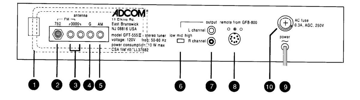
AM LOOP/ANTENNA 1 4 6
The GFT-555II is supplied with a high-sensitivity, ferrite-loop antenna that, for most convenient use, simply snaps into the bracket on the rear panel of the GFT-555II. Once you have mounted the ferrite loop on the bracket, connect the spade lugs on the two wires affixed to the ferrite loop to the two screws labeled G and AM and AM and the rear panel of the GFT-555II, you can "orient" the antenna for best reception of desired stations with minimum noise. In some very noisy locations, it may be necessary, for best reception, to remove the antenna from its bracket and position it away from the chassis of the GFT-555II. The length of the wires on the ferrite loop will permit some mobility. In such an Instance, simply attach the ferrite loop difficult cases, connecting the G and (Ground) terminal to the center screw on your AC-outlet wall plate, or to because of the extended high-frequency response and bandwidth of the AM tuner in the GFT-555II, more high-frequency noise will be received by the GFT-555II compared to ordinary auto or kitchen radios.
Should you find that you cannot get satisfactory reception using the AM ferrite loop, you may make your own AM antenna from a length of insulated wire. With AM, you'll find that the longer the wire, the stronger the signal. Also, an AM antenna made from wire will receive a station only when the antenna is broadside to the source, or transmitter, of the station. The higher the position of the antenna above ground, the better the reception will be. To install this type of antenna to the GFT-555II, connect one end of the antenna wire to the terminal on the rear panel of the GFT-555II labeled AM 1 . The other end of the antenna need not be labeled G 1 to the center screw of your AC-outlet wallplate, cold water pipe, or radiator. Please note that only one ground or "earth" connection can exist in a system. If your system has another ground connection, or plug, and connecting the G 1 screw to your AC-outlet wall plate or cold water pipe may create what is ground will be made through the three-prong AC-plug or ground connection on your other component and the
FM 2 3
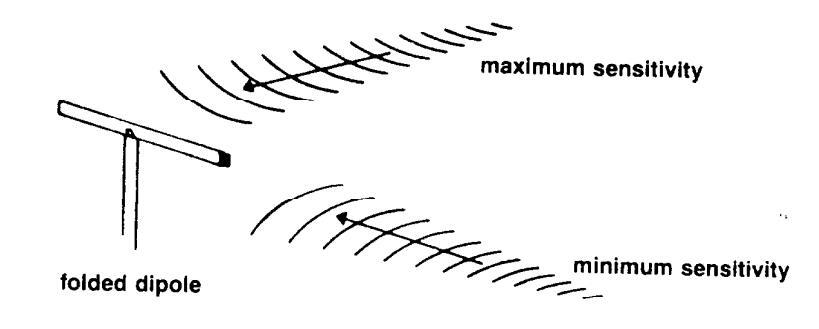
Your GFT-555II is provided with a simple FM folded-dipole wire antenna. Before the FM tuner can operate at all, this or another antenna must be connected. To connect the folded-dipole, attach the spade lugs at the end of the folded-dipole to the two screw terminals on the rear panel labeled 300Ω 3. The GFT-555II is also provided with a coaxial antenna input labeled 75Ω 2 for use with those systems or antennae using this type of wiring. All cable systems, for example, use 75Ω coaxial connections because of its superior noise and interference rejection characteristics.
The basic folded-dipole antenna included with you GFT-555II will allow you reception of strong local stations and signals free from "multipath" effects and interference. The "T" portion of the antenna should be fully extended and oriented for best reception of desired stations. Best reception will be obtained when the "arms" of the "T" face, or are broadside to, the direction of the incoming FM signal. You should try different vertical
and horizontal orientations until reception on most of the stations of interest is satisfactory. The dipole will not function well, if at all, if it is rolled up or casually dropped behind the GFT-555II or a piece of furniture.
If FM reception is particularly important to you, or if you find the dipole is inadequate for your reception needs, there are many inexpensive outdoor antennae that will permit you to realize the full potential of the FM tuner in the GFT-555II. Although an outdoor antenna is the best and easiest way to capture FM signals being broadcast, there are many new "electronic"-type antennae which can improve reception over the simple dipole and make orientation of the antenna a much simpler task. Please contact your ADCOM dealer to obtain further information about which specific antenna will provide the performance characteristics you require.
G d
This screw provides a ground connection to the chassis and is meant to furnish you with a ground terminal for the tuner in case you have need to install an AM-wire antenna (see AMLOOP/ANTENNA 4 5 above) or otherwise ground the tuner. You will find that the G 4 (Ground) connection will be helpful in areas of dry weather. Simply connect the G 4 screw to the center screw of your AC-outlet wall plate, cold water pipe or radiator, using 18-gauge zip cord or similar wire.
LOW/MID/HIGH
This switch permits you to adjust the output level from the OUTPUT jacks in 6dB increments. In the LOW position, the output from the tuner ( at 100% modulation) is 0.5 volt. In the MID position, the output from the tuner will be 1.0 volt and in the HIGH position, the output will be 2.0 volts. It is suggested that, before you connect your GFT-555II to your system, you set this switch to the LOW position. After connection, tune to your favorite station, or a station that you listen to frequently. Scan through the other sources that you may have plugged into your preamplifier (such as a CD Player, Cassette machine, etc.) with appropriate source material playing back from these sources. With your volume control at a comfortable listening level, set the three-position switch on the rear panel of the GFT-555II to that (when the preamplifier's selector switch is on "TUNER") which most closely approximates the volume level from the other sources. If your are using the GFT-555II with a passive control unit, it is recommended that you set the switch to the HIGH position. This will provide the maximum range of adjustment possible in the system. The output impedance of the GFT-555II (100Ω) remains constant regardless of the position of this switch.
OUTPUT
These jacks provide the audio output from the tuner. All that is required is to interconnect the LEFT and RIGHT OUTPUT to the corresponding left and right input jacks on your preamplifier or amplifier labeled "TUNER" or "AUX." Because the output impedance of the GFT-555II is extremely low, the load impedance that the preamplifier or amplifier presents to the OUTPUT is not critical and you will obtain optimal audio performance with virtually any input impedance.
REMOTE FROM GFB-800
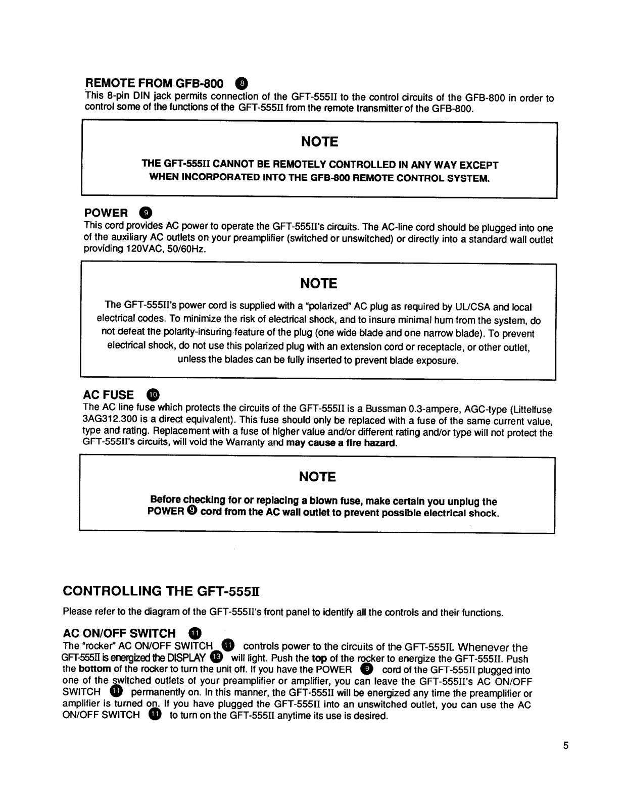
This 8-pin DIN jack permits connection of the GFT-555II to the control circuits of the GFB-800 in order to control some of the functions of the GFT-555II from the remote transmitter of the GFB-800.
NOTE
THE GFT-555II CANNOT BE REMOTELY CONTROLLED IN ANY WAY EXCEPT WHEN INCORPORATED INTO THE GFB-800 REMOTE CONTROL SYSTEM.
POWER
This cord provides AC power to operate the GFT-555II's circuits. The AC-line cord should be plugged into one of the auxiliary AC outlets on your preamplifier (switched or unswitched) or directly into a standard wall outlet providing 120VAC, 50/60Hz.
NOTE
The GFT-555II's power cord is supplied with a "polarized" AC plug as required by UL/CSA and local electrical codes. To minimize the risk of electrical shock, and to insure minimal hum from the system, do not defeat the polarity-insuring feature of the plug (one wide blade and one narrow blade). To prevent
electrical shock, do not use this polarized plug with an extension cord or receptacle, or other outlet,
unless the blades can be fully inserted to prevent blade exposure.
AC FUSE
The AC line fuse which protects the circuits of the GFT-555II is a Bussman 0.3-ampere, AGC-type (Littelfuse 3AG312.300 is a direct equivalent). This fuse should only be replaced with a fuse of the same current value, type and rating. Replacement with a fuse of higher value and/or different rating and/or type will not protect the GFT-555II's circuits, will void the Warranty and may cause a fire hazard.
NOTE
Before checking for or replacing a blown fuse, make certain you unplug the POWER O cord from the AC wall outlet to prevent possible electrical shock.
CONTROLLING THE GFT-555II
Please refer to the diagram of the GFT-555II's front panel to identify all the controls and their functions.
AC ON/OFF SWITCH
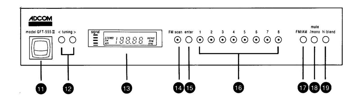
The "rocker" AC ON/OFF SWITCH 11 controls power to the circuits of the GFT-555II. Whenever the GFT-555II is energized the DISPLAY 13 will light. Push the top of the rocker to energize the GFT-555II. Push the bottom of the rocker to turn the unit off. If you have the POWER 9 cord of the GFT-555II plugged into one of the switched outlets of your preamplifier or amplifier, you can leave the GFT-555II's AC ON/OFF SWITCH 11 permanently on. In this manner, the GFT-555II will be energized any time the preamplifier or amplifier is turned on. If you have plugged the GFT-555II into an unswitched outlet, you can use the AC ON/OFF SWITCH 11 to turn on the GFT-555II anytime its use is desired.
TUNING 😰
These two buttons permit you to change the quartz-synthesized frequency shown on the DISPLAY 13 and to which the FM and AM sections are tuned. Pushing the left button will shift the tuned frequency to the next lower frequency. Pushing the right button will shift the frequency to the next higher frequency. The buttons work similarly for both the FM and AM bands. However, when the FM SCAN 14 button is pushed in (the LED in the center of the button will then illuminate), the tuner will automatically seek (either up or down in frequency, depending on which of the two TUNING 12 buttons is pushed) the next station with a good receivable signal. Whenever the LED in the center of the FM SCAN 14 is out, the scan function is inoperative and the normal mode is engaged. Please note that the FM SCAN is operative only on the FM band; it will not permit scanning the AM band.
In the normal mode, if either of the TUNING 1 2 buttons is depressed, the tuner circuitry will shift to the next frequency, up or down. If either button is depressed and held the display will index quickly, up or down in frequency, until the button is released.
DISPLAY
The multifunction fluorescent readout will display:
- 1. Your selection of either FM or AM band.
- 2. The frequency of the station to which you are tuned.
- 3. Whether an FM station is broadcasting stereo (when the signal received by the tuner is in stereo, the STEREO indicator will light in the display). Please note that if the MUTE/MONO B button is depressed, it will permit only mono reception and the STEREO indicator will not light, even if the broadcast itself is in stereo.
- 4. The relative signal strength of the station being received on both FM and AM. The SIGNAL strength indicator is divided into 5 segments. The greater the number of segments lit, the stronger the received signal. You can use the SIGNAL strength indicator to orient both FM and AM antennae for maximum signal and lowest distortion and noise.
- MEMO indicator will light whenever the ENTER 15 button is depressed to show that the station-preset memory is ready to receive instructions. (See ENTER 15 and STATION PRESETS 16 below).
FM SCAN
Depress this button to select the FM SCAN mode or the manual tuning mode. When the FM SCAN mode is activated, the LED in the center of the FM SCAN button will light. Once the FM SCAN mode is selected, pressing either of the TUNING buttons will cause the tuner to search the FM band, up or down in frequency, depending on which button is pressed, until a station with a good receivable signal is reached; the scan function will then stop. If you do not want to listen to the now-tuned station, press one of the tuning buttons and the scan function will be initiated once again.
NOTE
The FM SCAN (function will operate only on the FM band; its function is not available on the AM band. AM stations can be selected only using the manual mode. Whenever the AM band is chosen through the FM/AM (f) button, the LED in the center of the FM SCAN (f) button will be extinguished. Once the FM SCAN function is selected, it will remain activated, even if the GFT-555II is turned off. To deactivate the FM SCAN function, depress its button (f) once. The LED in the center of the button will extinguish and the FM tuner will return to the manual mode.
Whenever the LED in the center of the FM SCAN (4) button is not illuminated, the tuner is in the manual mode. In the manual mode, each time one of the TUNING (2) buttons is momentarily pressed, the tuner, and the DISPLAY (3) will shift to the next higher or lower frequency, depending on which of the TUNING (2) buttons is pushed. If one of the TUNING (2) buttons is pressed and held down , the tuner will index
quickly, up or down in frequency, until the button is released. This manual function is available on both the FM and AM bands.
ENTER 6
This button is used in conjunction with the STATION PRESETS 1 , below, to enter selected FM and AM stations into the GFT-555II's memory.
STATION PRESETS
The GFT-555II has a capability to store 8 separate FM and 8 separate AM stations in its memory. The stations in the memory bank of the GFT-555II can be changed at will, and at random, any time you desire. To program stations in the memory:
- 1. Select either the FM or the AM band through FM/AM 1 button.
- 2. Tune to the frequency of the station you desire to program into the memory through TUNING buttons. If you are programming stations on the FM band, you may find it more convenient to search for the specific station by using the FM SCAN for function.
- 3. Press ENTER 15 button. MEMO will light up in the DISPLAY 13 to show memory is ready to accept instructions.
- 4. Press one of the 8 buttons in the station-preset rack. The MEMO will disappear from the DISPLAY and the LED in the center of the selected button will glow to show that the memory has been programmed for that station's frequency. Now, each time that specific button is pressed, the tuner will automatically return to the programmed frequency and station. The presets do not have to be programmed in any sequence, numerical or otherwise. They can be programmed in any desired order on either FM or AM
- bands.
- 5. Repeat steps 2 to 4 to program any other stations in which you are interested up to a total of 8.
FM/AM
Press this button to switch from FM to AM and vice-versa. The selected band will be indicated on the DISPLAY 13. Whenever you change bands, the tuner will automatically return to the station (frequency) or PRESET 15 to which the band was tuned previously.
MUTE/MONO 13
The GFT-555II features a "muting" circuit to reduce, or eliminate, the normal FM noise present between stations. Were it not for the muting circuit the loud "rushing" noise between stations could soon become annoying. The muting circuit, however, may make it difficult to receive very weak stations which are near the level of the interstation noise. In such instances, the muting circuit will mute not only the noise, but the weak station as well. To defeat the muting circuit, simply push in the MUTE/MONO [13] button. This switch will automatically defeat the muting circuit and "blend" the left and right channels of the original stereophonic broadcast into a monaural signal for maximal noise reduction. This will allow very weak stations to be received in mono mode which would otherwise be unlistenable in stereo mode. (It is very unlikely that a stereophonic signal below the "mute" threshold will be acceptable for listening even if the HI BLEND [19] circuit is activated. See HI BLEND [19] below.) Whenever the MUTE/MONO [13] button is depressed and the tuner is in MONO mode, the STEREO Indicator in the DISPLAY [13] will not light.
HI BLEND
This switch, when depressed, inserts a "high-frequency blend" network which will substantially reduce high-frequency noise present with very weak stations. Due to the formatting of FM stereo signals onto the FM carrier, weak signals permit a considerable amount of noise to creep in and confuse the stereo signal. The ADCOM HI BLEND circuit reduces the high-frequency separation of the stereo signal, without compromising the remainder of the stereophonic information, and thereby cancels out much of the hiss and high-frequency noise in the signal. It is a phenomenon of FM that noise injected into the stereo-channel information is mostly out-of-phase, and simply "blending" the channels partially will cancel out and reduce the noise significantly, without sacrificing signal fidelity or overall separation. Should you find that even with the HI BLEND circuit the received signal is too noisy and further noise reduction is required, depress the MUTE/MONO button. This will automatically remove the stereo information and decrease the noise substantially, albeit at the expense of the stereophonic information. Please note that when the MUTE/MONO button is depressed, the STEREO indicator in the DISPLAY will not light. (See MUTE/MONO button)
CARING FOR YOUR GFT-555II
Great care has been taken by ADCOM to assure that your Tuner is as flawless in appearance as it is electronically. The front panel is a heavy-gauge, high-grade, anodized aluminum extrusion, bead-blasted for durability. The bottom cover, chassis, top cover and rear panel are of heavy-gauge steel, both painted and baked. If the front panel, top or sides should become dusty or fingerprinted, they can be cleaned with a soft lintless cloth, slightly dampened with a very mild detergent solution.
NOTE
DO NOT SPRAY OR USE LIQUIDS OF ANY KIND ON THE SURFACES OF THE GFT-555II
SERVICING
ADCOM has a Technical Service Department to answer questions pertinent to the installation and operation of your unit. In the event of difficulty, please contact us for prompt advice. If your problem cannot be resolved through our combined efforts, we may refer you to an authorized repair agency, or authorize return of the unit to the factory. To aid us in directing you to a convenient service station, it would be helpful if you indicate which major city is accessible to your home.
Please address mail inquiries to: ADCOM Service Corp. 11 Elkins Road East Brunswick, NJ 08816
For telephone inquiries call: Monday through Friday 9 AM to 4 PM Eastern Time (201) 390-1130
For fax inquiries: (201) 390-9152. Please include a return fax number for the reply.
When calling or writing about your GFT-555II, be sure to note and refer to its model and serial numbers as well as the date of purchase and the dealer from whom the unit was purchased. In the event that the unit must be returned to the factory for service, you will be instructed as to the proper procedure when you call or write for a Return Authorization.
UNDER NO CIRCUMSTANCES SHOULD YOUR UNIT BE SHIPPED TO THE FACTORY WITHOUT PRIOR AUTHORIZATION, OR PACKED IN OTHER THAN ITS ORIGINAL CARTON AND FILLERS.
If the original shipping carton and its fillers have been lost, discarded, or damaged, a duplicate carton may be obtained from our Service Department for a nominal charge. Inquire as to the procedure when requesting a Return Authorization.
Always ship PREPAID via United Parcel Service (UPS) or other approved carrier. DO NOT SHIP VIA PARCEL POST, since the packing was not designed to withstand rough Parcel Post handling. FREIGHT COLLECT SHIPMENTS CANNOT BE ACCEPTED.
SPECIFICATIONS
GFT-555II
FM Tuner Section
| Llashla Sansitivity (Mono) | |
|---|---|
| Quieting Sensitivity (50dB) | 2 6uV//13 7dBf |
| Mono | 2.0µV/36dBf |
| Stereo | 54μ 9/5005 |
| Signal-to-Noise (@65dBf, "A" Weighted) | 85dB |
| Mono | 76dB |
| Stereo | |
| THD + Noise (@ 1kHz, 65dBf) | 0.035% |
| Mono | |
| Stereo | 1.5dB |
| Capture Ratio | >75dB |
| Alternate Channel Selectivity (±400kHz) | ≥85dB |
| IF Rejection | ≥90dB |
| Image Rejection (±400kHz) | ≥60dB |
| Separation (@ 1kHz) | 30Hz–15kHz |
| Frequency Response (±0.5dB) | 100Ω |
| Output Impedance | I ∩W~0 5V MFD≈1.0V. HIGH≈2.0V |
| Output Level | LOW~0.0V, MED MOV, COM |
AM Tuner Section
| 300µV/m | |
|---|---|
| Sensitivity | ≥40dB |
| Selectivity (±10kHz) | ≥40dB |
| Image Rejection | ≥80dB |
|
IF Rejection
Signal-to-Noise (@ 5mV/m, "A" Weighted) |
47dB |
General
| which is the such as a provider of the second second order) | 120VAC/50-60Hz |
|---|---|
| Power (available in other voltages on special order) | 10 Watts |
| Power Consumption | 17"(432mm)x11 3/8"(289mm)x3"(76mm) |
| Chassis Dimensions | 17"(432mm)x12 3/4"(324mm)x3 1/4"(83mm) |
| Maximum Dimensions | 10.5lbs.(4.8kg) |
| Weight | |
| Weight, Packed |
SPECIFICATIONS SUBJECT TO CHANGE WITHOUT PRIOR NOTICE
ADCOM 11 Elkins Road East Brunswick, NJ 08816 Telephone (201) 390-1130


 Loading...