

Page 1

A>COM
c/efo//s you can hear
GFP-750
Stereo Preamplifier
©
OWNER’S MANUAL
Page 2
THE FOLLOWING PRECAUTIONS AND SAFETY INSTRUCTIONS
ARE REQUIREMENTS OF UL AND CSA SAFETY REGULATIONS
Warning: To reduce the risk of fire or electric shock, do not expose
this unit to rain or moisture.
CAUTION
RISK OF ELECTRIC SHOCK
A
DO NOT OPEN
AVIS: RISOUE DE CHOC ELECTRIQUE-NE PAS OUVRIR
The graphic symbol of a lightning flash with an arrow
point within a triangle signifies that there is dangerous
voltage within the unit and it poses a hazard to anyone
removing the cover to gain access to the interior of the
unit.Only qualified service personnel should make
any such attempt.
The graphic symbol of an exclamation point within an
equilateral triangle warns a user of the device that it is
necessary to refer to the instruction manual and its
warnings for proper operation of the unit.
Do not place this unit on an unstable cart, stand, tripod,
bracket, or table. The unit may fall, causing serious
injury to a child or adult, and serious damage to the
unit. Use only with a cart, stand, tripod, bracket, or table
recommended by the manufacturer, or sold with the
unit. Any mounting of the device should follow the man
ufacturer's instructions, and should use a mounting ac
cessory recommended by the manufacturer.
Read all the safety and operating instructions before connecting or using
this unit.
Retain this notice and the owner’s manual for future reference.
All warnings on the unit and in its operating instructions should be adhered to
All operating and use instructions should be followed.
Do not use this unit near water; for example, near a bathtub, washbowl,
kitchen sink, laundry tub, in a wet basement, or near a swimming pool.
The unit should be installed so that its location or position does not interfere
with its proper ventilation. For example, it should not be situated on a bed,
sofa, rug, or similar surface that may block the ventilation openings; or
placed in a built-in installation, such as bookcase or cabinet, that may
impede the flow of air through its ventilation openings.
The unit should be situated away from heat sources such as radiators, heat
registers, stoves, or other devices (including amplifiers) that produce heat.
The unit should be connected to a power-supply outlet only of the voltage
and frequency marked on its rear panel.
The power-supply cord should be routed so that it is not likely to be walked
on or pinched, especially near the plug, convenience receptacles, or where
the cord exits from the unit.
1
ATTENTION
POUR PRÉVENIR LES CHOCS ÉLECTRIQUES NE PAS UTILISER
CETTE FICHE POLARISÉE AVEC UN PROLONGATEUR, UNE PRISE
DE COURANT OU UNE AUTRE SORTIE DE COURANT, SAUF SI LES
LAMES PEUVENT ÊTRE INSÉRÉES À FOND SANS EN LAISSER AU
CUNE PARTIE À DÉCOUVERT.
CAUTION
TO PREVENT ELECTRIC SHOCK DO NOT USE THIS POLARIZED PLUG
WITH AN EXTENSION CORD, RECEPTACLE OR OTHER OUTLET UN
LESS THE BLADES CAN BE FULLY INSERTED TO PREVENT BLADE
EXPOSURE.
CAUTION
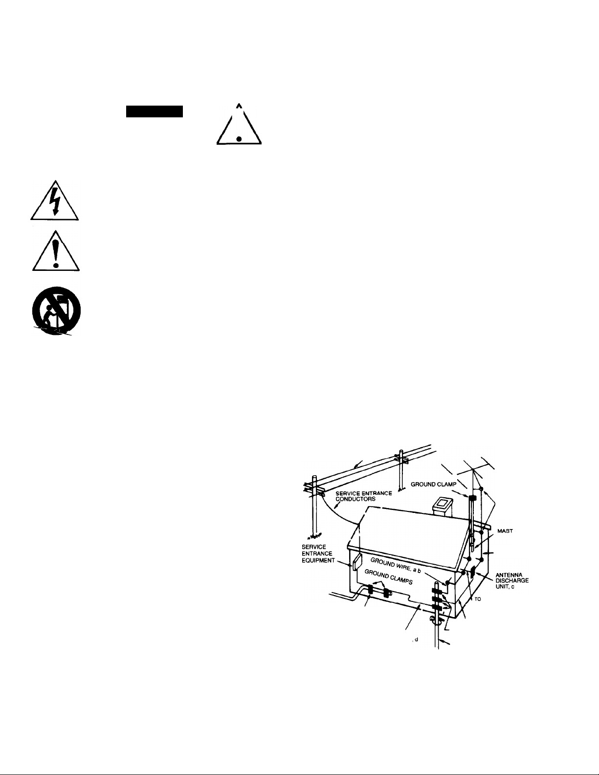
Any outdoor antenna must be located away from all power lines.
POWER LINES
OUTDOOR ANTENNA GROUNDING
If an outside antenna is connected to your tuner or tuner-preamplifier, be
sure the antenna system is grounded so as to provide some protection
against voltage surges and built-up static charges. Section 810 of the
National Electrical Code, ANSI/NFPA No. 70-1984, provides information with
respect to proper grounding of the mast and supporting structure, grounding
of the lead-in wire to an antenna discharge unit, size of grounding
conductors, location of antenna discharge unit, connection to grounding
electrodes, and requirements for the grounding electrode.
a. Use No.10 AWG (5.3 mm^) copper, No.8 AWG (8.4 mm^) aluminum.
No. 17 AWG (1.0 mm") copper-clad steel or bronze wire, or larger, as a
ground wire.
b. Secure antenna lead-in and ground wires to house with stand-off
insulators spaced from 4-6 feet (1.22-1.83 m) apart.
c. Mount antenna discharge unit as close as possible to where lead-in
enters house.
d. Use jumper wire not smaller than No.6 AWG (13.3 mm") copper, or the
equivalent, when a separate antenna-grounding electrode is used. See NEC
Section 810-21 (j).
EXAMPLE OF ANTENNA GROUNDING AS PER NATIONAL ELECTRICAL CODE INSTRUCTIONS
CONTAINED IN ARTICLE 810 - RADIO AND TELEVISION EQUIPMENT.
POWER LINES
STANDOFF
INSULATORS, b
ANTENNA
LEAD-IN WIRE
Clean unit only as recommended in its instruction manual.
The power-supply cord of the unit should be unplugged from the wall outlet
when it is to be unused for a long period of time.
Care should be taken so that objects do not fall, and liquids are not spilled,
into the enclosure through any openings
This unit should be serviced by qualified service personnel when:
A. The power cord or the plug has been damaged; or
B. Objects have fallen, or liquid has been spilled, into the unit; or
C. The unit has been exposed to rain, or liquids of any kind; or
D. The unit does not appear to operate normally, or exhibits a
marked change in performance; or
E. The device has been dropped, or the enclosure damaged.
DO NOT ATTEMPT SERVICING OF THIS UNIT YOURSELF.
REFER SERVICING TO QUALIFIED SERVICE PERSONNEL.
EXTERNAL ANTENNA
POWER SERVICE GROUNDING
ELECTRODE SYSTEM
(e. g. interior metal water pipe)
BONDING JUMPER
OPTIONAL ANTENNA GROUNDING
ELECTRODE DRIVEN 8 FEET (2.44 M) INTO
THE EARTH IF REQUIRED BY LOCAL
CODES. SEE NEC SECTION 810-21 (1)
TERMINALS OF RADIO RECEIVER
GROUND WIRE, a.b
GROUND CLAMPS
NOTE TO CATV SYSTEM INSTALLER
This reminder is provided to call the CATV system installer's attention to
Article 820-22 of the National Electrical Code that provides guidelines for
proper grounding and, in particular, specifies that the cable ground shall be
connected to the grounding system of the building, as close to the point of
cable entry as practical.
Page 3
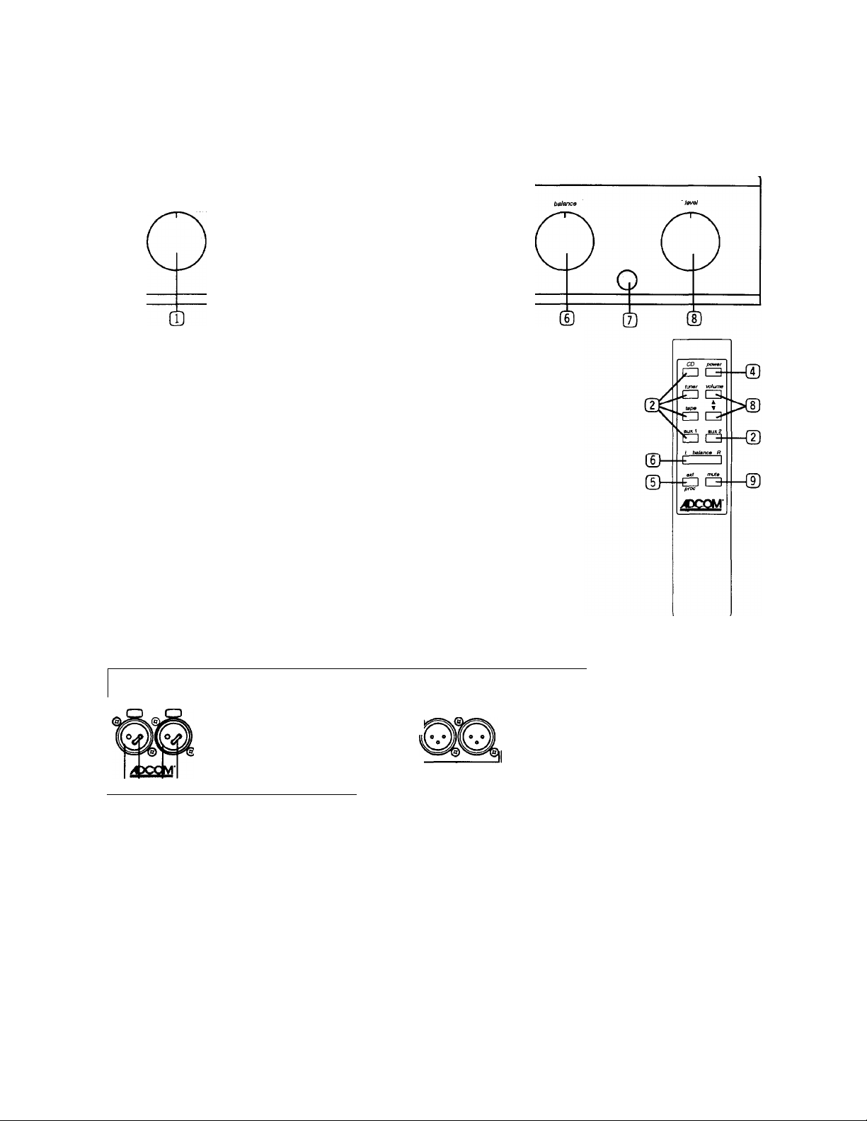
1. PRODUCT DESCRIPTION
1.1. GFP-750 Front Panel Diagram & Remote Control
Ш
0 CD О
pa$siv0 power processor
9 9 9
О
(Ю ® СЮ
Stereo/Reverse/Mono
©
©
©
©
©
©
©
Input Source Selection
Passive Mode On/Off
Power On/Off
External Processor
Balance Control
Infrared Remote
Control Sensor Lens
Volume Control Adjust volume level
Mute
Switch (reverse) or combine (mono) channels
Select input source
Bypass active gain stages
Turn unit on and off.
Engage external processor
Adjust balance level
Receiver for remote control IR signal
Engage Mute circuitry
GFP-750 Rear Panel Diagram
1.2.
balanced CO input unbalanced inputs » laps p processor ^ p unbal outpu& ^ p balancect mam 3 output
Γ
top Is L channel bottom is R channel
@p©p ©p ©p ©p
,,@°® @©.@ъ.@©,@°©, I
Mo0elGFP-7S t siBreo preamplitier Wan ng: To r»6uc» the sk ot elactnc sfioc -, do noi expose this equipm nt to rain or moislure.
10 Timber Lan»
Mariboro, NJ 07746
Power: ItSVAi SO-бОНг
Pbwarcansun itìon(max):30W Avis: Vaque líe choc ek Л1рае-ne pese
0^ ®
® CD Balanced Inputs
(TI) Gold Jumpers
QD Unbalanced Stereo Inputs
(B) Tape Loop Stereo In/Out
@ External Processor
Loop Stereo In/Out
Aire/ ion: pour evitar bv lìrisque de leu au hoc elactrique, ne pas expo:
© ©
Main 1 and Main 2
©
Unbalanced Stereo Outputs
Main 3
©
Balanced Stereo Outputs
Remote Control Infrared
©
repeater outputs (x 2)
Remote Control
©
Sensor Input
1
' се! аррвгеН а Ш phiie с
IR expar/der remote sensor
©
о о.
switched АС outet
©
О.
©
"АН
Master On/Off Switch
AC Power Cord Socket
Switched AC Outlet
Л
Page 4

1.3. Product Features
(T) Stereo/Reverse/Mono Switch
This switch is used to change the polarity of the input signal in relation to the output signal. The
stereo setting allows normal playback of the input signal. The reverse setting inverts the phase of the
input signal. The mono setting combines both channels for a monaural input signal or where
speaker placement does not accommodate stereo playback.
(T) Input Selection
The input selection knob has a digital interface that senses movement of the knob. The knob appears to
turn freely as the interface detects the direction the knob is being turned and indexes through the input
sources accordingly. To go from aux 2 [o tuner or from tuner to aux 2, you must index back through the
other input sources.
(T) Passive
This features allows the active gain stages of the preamp to be bypassed. (A slight drop in volume level is
expected when this feature is engaged.) This feature has no effect when the processor feature is en
gaged.
(T) Power On/Off
The GFP-750 is turned on by pressing either the remote control power button or toggling the front
panel power switch. The LED above the power switch will come on indicating the unit is on. (The
power status LED will glow slightly dimmer when the unit is muted.)
© Processor Switch
Engages the processor loop when activated. See for further information.
© Balance Control
The GFP-750 balance control feature provides finer balance adjustment allowing for greater balance
accuracy and will not entirely mute either channel.
© Infrared Remote Control Sensor Lens
This lens protects the infrared receiver which receives commands from the remote control. The pathway
between the lens and remote control must be free of obstructions for the remote control to operate the
GFP-750.
© Volume Control
The front panel volume control knob is motorized. It may be adjusted either by hand or by the volume
buttons on the remote control. The volume knob’s groove always indicates the present volume level. The
volume control knob may be used to reduce the volume level while the GFP-750 is muted without deac
tivating the mute feature.
© Mute
The GFP-750’s mute feature is engaged by pressing the mute button on the remote control. This feature
fully mutes the outputs. To deactivate the mute feature, press the mute button again or either of the two
volume buttons on the remote control. {Turning the front panel volume knob will not deactivate the mute
feature.)
© Balanced CD Inputs
Before using the balanced CD inputs, it is necessary to remove the gold jumpers located between pins 1
and 3 in both connectors. (See the figure to the right.) When switching from balanced CD inputs to
unbalanced CD inputs, you must replace the jumpers between pins 1 and 3 as shown.
|| DO NOT USE BOTH BALANCED AND UNBALANCED CD INPUTS AT THE SAME TIME.^
di) Gold Jumpers
When using the unbalanced CD inputs, jumpers must be installed to short pins 1 and 3 of the
balanced input jacks.
© Unbalanced Stereo Inputs gold jumpers
Connect the various outputs from each signal source to these unbalanced stereo inputs. Do
not connect both the unbalanced and balanced CD inputs at the same time. See the section
labeled CONNECTIONS for further information regarding these inputs.
3
Page 5

(ID Tapeln/out
The tape outputs are fixed level outputs. The signal is selected by the input source knob or input buttons
on the remote control. (The tape outputs are muted when tape is selected as the input source or when the
processor loop is engaged.)
Processor
The processor in/out connectors allow for convenient connection of an external processor, like ADCOM’s
GSA-700 surround sound processor. The connection diagrams under Audio/Home Theater and Multi-
Channel Audio detail basic connection methods that take advantage of this feature. When the processor
feature is activated the external processor controls the volume and balance of the system.
@ Main Unbalanced Stereo Outputs
Main 1 is an unbalanced line level stereo output to be connected to the amplifier’s unbalanced inputs.
Main 2 accommodates a second amplifier for multi-room or multi-zone operation.
(iD Main Balanced Stereo Outputs
Main 3 is a balanced line level stereo output for use with amplifiers that utilize balanced inputs.
(ID Remote Control Infrared Repeater Output
Connect the ACCOM IRA-50011 infrared repeater to control other remote controlled equipment via the
remote sensor extension.
liD Remote Control Sensor Input
Connect either the ACCOM XR-500II or SPM-500II to extend the remote control capabilities of the GFP750 via an external room or zone.
Master On/Off Switch
The rear panel Master On/Off Switch allows the unit to be electrically disconnected from
the AC power source without having to remove the AC power cord. We recommend the
Master On/Off switch be pushed to the “O” (off) position when the unit will be left unat
tended for an extended period of time.
IF THE GFP-750 DOES NOT RESPOND TO REMOTE CONTROL COMMANDS, AND THE AC POWER CORD IS INSTALLED, CHECK THAT THE
MASTER ON/OFF SWITCH IS IN THE “I” ON POSITION.
2. CONNECTIONS
2.1. Connecting the GFP-750
Page 6

2.2. Adding an External Processor
Note: These diagrams represent a basic audio/video system using the GFP-750 with various other audio
equipment. Additional audio and video sources may easily be added to the system following similar connections
as shown. Refer to your other owner’s manuals for more detailed connection information.
Page 7

3. TROUBLE SHOOTING
Symptoms
Unit does not respond to front panel
power switch or remote control power
-AC power cord not connected
-Master On/Off switch is off
Possible Causes
button.
Power LED is dimmer than the other
-Preamp is muted. (Power LED is dimmed when outputs are muted.)
status LED’s.
No signal at main outputs
-Wrong source selected
-The external processor feature is activated (processor LED is on) without
the external processor either being on or connected properly. (The main
outputs are connected to the processor in inputs when in the external
processor feature is activated.)
-Preamp is muted. (Power LED is dimmed when outputs are muted.)
No signal at tape outputs
-The input device is on tape.
-The external processor feature is activated. (Processor LED is on)
(tape out is disconnected when tape is selected as the
source or the processor feature is activated.)
Volume level is reduced when going to
passive mode
-A slight reduction in volume level is to be expected as the
active gain stages are bypassed when the passive
feature is engaged.
The volume and balance controls do
not function.
-The volume and balance controls are bypassed when
the processor feature is engaged. Either use the controls
on the external processor or switch the processor feature off.
4. CARE AND MAINTENANCE
The GFP-75ffs steel chassis and extruded aluminum front panel are specially coated to provided a durable and
attractive finish. To remove dust and finger smudges, merely dampen a cloth and wipe off the chassis. Do not use
strong solvents or detergents. Many are very abrasive or corrosive. Never spray or pour any liquid onto the
chassis or front panel. In the event of any liquid getting into the chassis, unplug the unit from the AC outlet
immediately.
5. SERVICING
ACCOM’s Technical Service Department will be happy to answer all questions pertaining to the installation and
operation of your unit. In the unlikely event of difficulty, please contact us for prompt advice. If we cannot help you
resolve the problem immediately, we may refer you to an authorized repair agency, or authorize the return of your
unit to our plant.
All written inquiries should be addressed to;
ADCOM Service Department
10 Timber Lane
Marlboro, NJ 07746 USA
(732) 683-2356 Phone (732) 683-9792 Fax
Telephone inquiries are welcome from Monday through Friday between 9 AM and 4 PM, Eastern Standard Time.
We will also be glad to answer any FAX inquiries. Please include your phone and FAX numbers so we can
respond.
When inquiring about your unit, please include the serial number, the name of the dealer from whom you pur
chased the unit, and the date of purchase.
If we ask you to return the unit to us for service, we will issue a specific Return Authorization number for your use.
UNDER NO CIRCUMSTANCES SHOULD THE UNIT BE SHIPPED TO US WITHOUT PROPER AUTHORIZA
TION OR PACKED IN ANYTHING OTHER THAN ITS ORIGINAL PACKING.
If the original packing has been lost, discarded or damaged, we will gladly supply replacement packaging at a
nominal charge. Please mention your need when you contact us.
Always ship PREPAID via UPS (United Parcel Service) or other appropriate carrier. FREIGHT COLLECT SHIP
MENTS WILL BE REFUSED.
DO NOT SHIP VIA PARCEL POST as the packaging will not necessarily withstand the handling by our Postal
Service.
Page 8

6. GFP-750 SPECIFICATIONS
Output Level (Rated) i .ov
THD+N @ Rated Output (20Hz to 20kHz)
Balanced............................................................................................................................... <0.025%
Unbalanced.........................................................:..................................................................<0.095%
THD+N @ Rated Output (1 kHz)
Balanced.................................................................................................................................<0.015%
Unbalanced.............................................................................................................................<0.017%
Output Impedance
Balance...................................................................................................................................<1200£2
Unbalanced Outputs................................................................................................................<60011
Input Impedance
Balanced..................................................................................................................................... 94k£l
Unbalanced.................................................................................................................................. 47kll
Frequency Response (Balanced and Unbalanced)
20Hz to 20KH2...................................................................................................................+0, -0.25dB
IM Distortions (@ Rated Output)
CCIF from 4kHz to 20kHz (Balanced)
CCIF from 4kHz to 20kHz (Unbalanced)................................................................................<0.035%
SMPTE (Balanced).................................................................................................................< 0.05%
SMPTE (Unbalanced).............................................................................................................< 0.05%
....................................................................................
<0.009%
Signai to Noise Ratio (Ref. to 1 volt)
“A” Weighted (Balanced).........................................................................................................>102dB
“A” Weighted (Unbalanced).....................................................................................................>102dB
Input Sensitivity (@ Rated Output)
Balanced...................................................................................................................................183mV
Unbalanced...............................................................................................................................365mV
GENERAL SPECIFiCATiONS
Power (available in 230V by special order)
.................................................................
ii5VAC-50/60Hz
Power Consumption....................................................................................................................................30 va
Chassis Dimensions....................................................................3 1/2” (89mm) x ir (432mm) x 11" (279mm)
Maximum Dimensions...............................................................41/8" (losmm) x 17" (432mm) x i2"(305mm)
Weight....................................................................................................................................................isibs (6.8kg)
Weight, Packed................................................................................................................................. 17 ibs. (7.7kg)
 Loading...