

Page 1
Hydraulic divider
Diviseuse hydraulique
Spezzatrice idraulica
Instructions for us e an d m ainte n anc e
Notice d’utilisation et de maintenance
Istruzioni
uso e manutenzione
Code/codice N° 8H500100 rev. 00
November/Novembre/Novembre 2005
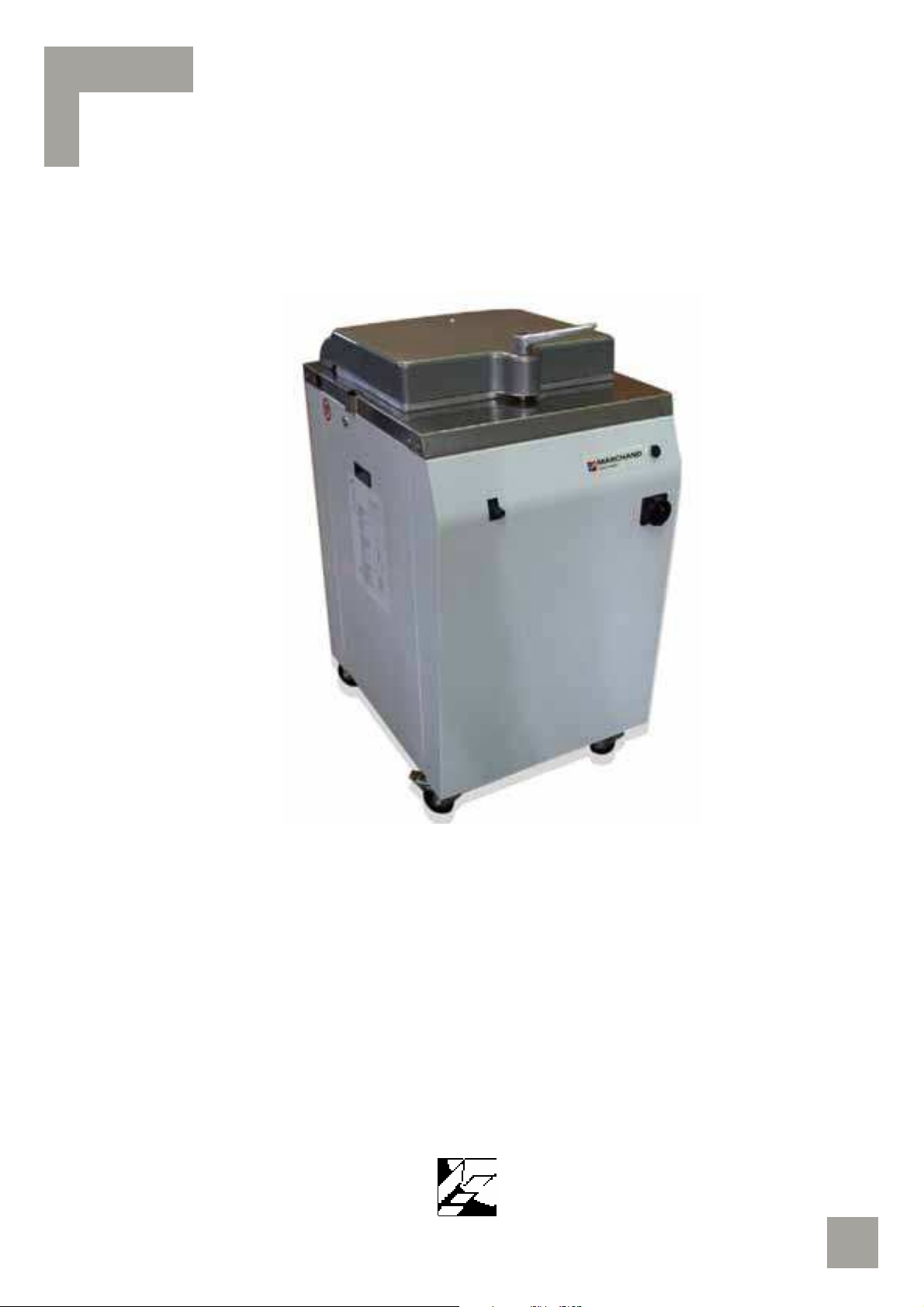
CONCORDE 3
MERCURE 3
Page 2

Page 3

3
ENGLISH
P. 5
FRANCAIS P. 27
ITALIANO P. 49
Tables with spare parts
Planches avec pièces détachées
Tavole con ricambi
P. 71
Wiring diagrams
Schémas électriques
schemi elettrici
P. 101
CAREFULLY READ THIS INSTRUCTION MANUAL
BEFORE OPERATING THE MACHINE
OBSERVE ALL SAFETY REGULATIONS AND INSTRUCTIONS
DURING OPERATION OF THE MACHINE
LIRE ATTENTIVEMENT CE MANUEL D’INSTRUCTIONS
AVANT DE METTRE EN ROUTE LA MACHINE.
OBSERVER LES CONDITIONS ET LES INSTRUCTIONS DE SECURITE PENDANT
LE FONCTIONNEMENT DE LA MACHINE
LEGGERE ATTENTAMENTE IL PRESENTE MANUALE D’ISTRUZIONI
PRIMA DI FAR FUNZIONARE LA MACCHINA.
OSSERVARE LE NORME E LE ISTRUZIONI DI SICUREZZA
DURANTE IL FUNZIONAMENTO DELLA MACCHINA
GENERAL INDEX/INDEX GENERAL/INDICE GENERALE
Page 4

Page 5

5
ENGLISH
Page 6

Page 7

TABLE OF CONTENTS
Page
Presentation, general warnings and warranty rules 9
1. Machine identification 10
2. Technical specifications 11
3. Intended use 13
SECTION A 4. Machine description 13
5. Preventive measures against health and safety hazards 14
6. Safety signs - symbols 16
1. Transport, handling and storage 17
2. Preparing the room - Installing the machine 18
3. Start-up, use and adjustments 19
SECTION B 4. Troubleshooting 21
5. Food hygiene and cleaning 23
6. Maintenance and checks 23
7. Replacing worn parts 26
SECTION C 1. Emergencies 26
2. Decommissioning - scrapping 26
ALPHABETICAL INDEX
emergencies 26
decommissioning, scrapping 26
food hygiene and cleaning 23
general warnings 9
intended use 13
machine controls 19
machine description 13
machine identification 10
machine installation 18
maintenance and checks 23
preparing the room 18
presentation 9
preventive measures against electrical hazards 14
preventive measures against health and safety hazards 14
preventive measures against mechanical hazards 14
preventive measures against noise hazards 16
preventive measures to guarantee hygiene 15
replace of worn out parts 26
safety signs - symbols 16
start-up and work cycle 23
start-up, use and adjustments 19
technical specifications 11
transport, handling and storage 17
troubleshooting 21
warranty rules 10
7
Page 8

Page 9

PRESENTATION, GENERAL WARNINGS AND WARRANTY RULES
PRESENTATION
This instruction manual has been designed and organised for quick easy reference. For this
purpose, in addition to the INTRODUCTION and GENERAL WARNINGS, it contains a TABLE OF
CONTENTS and an INDEX.
For each topic discussed, illustrations and tables are provided beside the corresponding text
to facilitate understanding.
The instruction manual is divided into two SECTIONS.
For the topics discussed in each SECTION, refer to the detailed TABLE OF CONTENTS.
GENERAL WARNINGS
This instruction manual is intended for the owner/user of the machine, the personnel
employed by the latter in positions of responsibility within the company and personnel
assigned to handling, installation, use, supervision, maintenance and scrapping of the
machine etc.
This manual provides information on the technical specifications and scheduled use of the
machine, instructions/indications/information on handling, installation, assembly, adjustment
and use in addition to information on personnel training in order to facilitate maintenance
work, troubleshooting, ordering of spare parts, residual risk assessment etc.
This manual forms an integral part of the MACHINE which is DESIGNED FOR PROFESSIONAL
USE but the manual should never be considered a substitute for adequate user training and
experience. Operations requiring personnel with specific skills are highlighted in the manual.
The manufacturer reminds its customers, i.e. users of the machine, that they are also
required to observe the specific legislation concerning places of work and that adequacy and
conformity of the work place with current regulations are essential conditions for correct
installation and use of the machine.
The manufacturer’s modern facilities - STUDY AND DESIGN DEPARTMENT, AFTER-SALES
SERVICE, ASSEMBLY TEAM - enable it to satisfy all customer requirements extremely quickly.
This manual should be considered part of the machine and must be kept for future reference
until the machine is scrapped.
This manual must be kept in a dry easily accessible place, preferably within easy reach of the
machine.
This manual reflects the state of the art existing at the time the machine is sold and cannot
be considered inadequate simply because it is later updated in the light of further experience.
The manufacturer reserves the right to update the machine and instruction manuals without
being obliged to update machines and/or manuals produced previously, barring exceptional
circumstances. On request, however, the manufacturer will provide customers with any
further information they may require and will be pleased to receive any customer suggestions
for improvement of this manual.
If the machine is sold, customers (users) are kindly requested to notify the manufacturer of
the address of the new owner for the above-mentioned purpose.
9
Page 10

Instructions for use and maintenance
Hydraulic divider
CONCORDE—MERCURE
The manufacturer accepts no liability in the event of the following:
a. inappropriate use of the machine or use by personnel not trained to operate professional
machines
b.use not in compliance with specific national regulations
c.incorrect installation
d.power supply faults
e.lack of maintenance
f.unauthorised modifications or work
g.use of non-original spare parts or parts not specifically intended for the model
h.total or partial failure to observe the instructions
i.exceptional events etc.
WARRANTY RULES
The machine is guaranteed for 12 (twelve) consecutive months from the date of purchase on
condition that it is used according to the instructions contained in this manual. The warranty
lapses if the machine has been used without following the directions contained in the manual
or if the machine has been repaired, disassembled or modified by unauthorised workshops or
after-sales centres. All electrical parts are excluded from the warranty if the damage has been
caused by incorrect use of the machine.
SECTION A - POINT 1
MACHINE IDENTIFICATION
Figure n° 1 shows the plate affixed to the machine in the position indicated by the arrow in
figure n° 2. The plate contains all the information necessary for identifying the machine.
10
Figure n° 2
Page 11

SECTION A - POINT 2
TECHNICAL SPECIFICATIONS
The main technical specifications of the machine are illustrated and indicated in figure n° 3
and in the following table.
Figure n° 3a - Mercure
11
Page 12

12
Instructions for use and maintenance
Hydraulic divider
CONCORDE—MERCURE
Figure n° 3b - Concorde
Page 13

SECTION A - POINT 3
INTENDED USE
The machine is intended for traditional bakeries and small and large food laboratories and is
used to divide dough into dough pieces of different size and weight.
Other uses of the machine may be dangerous for user and machine. Similarly conditions of
installation and/or use other than those given in the chapter “FACILITIES - INSTALLATION”
and “START-UP, USE AND ADJUSTEMENT” may cause damage to user and machine.
SECTION A - POINT 4
MACHINE DESCRIPTION
The machine consists of a tank sealed by a corrosion-proofing
aluminium alloy lid with a plate of plastic material suitable for
food contact, the bottom of which goes up and down on
command. This bottom is made up of small plates coated with a
special plastic to avoid that the dough sticks. Stainless steel
knives lower within these small plates.
The movement of bottoms and knives is ensured by a piston
located in the lower part.
On moving the lever, the small plates smash the dough at a
pressure that is enough to create a homogeneous dough
distribution. Once this homogeneous dough has been obtained,
the knives are automatically raised to have the dough cut into
portions.
This machine has been designed after a careful selection of the
main requirements in terms of food distribution.
Moreover, any suggestions coming from the main users in the
food sector have been collected, also in view of their operating
needs. The idea was developed taking into the highest account the requirements provided for
by the new CE regulations.
Figure n° 4
MANUFACTURING CHARACTERISTICS
-Tank (round for CONCORDE and rectangular for MERCURE versions) made of an alloy fit for
food contact.
-Milled stainless steel knives.
-Tank edge machined so as to allow air outlet.
-Lid locking by means of a hot-pressed eccentric.
-Lid pressure ensured by a double-effect hydraulic system.
-Aluminium casting piston carrier.
-Motorization provided with thermal protection.
-Motor driven by a hydraulic pump fed by a 19 dm3 oil tank.
-Structure mounted on directional wheels, two of which provided with brakes.
-Epoxidated painting fit for food contact.
-The smooth surface (natural polyamide) of the enbloc small plates prevents the dough from
sticking to the tank, thus ensuring hygiene and reduced maintenance operations.
The electrical connections are enclosed in a hermetically sealed box located within the
structure.
13
Page 14

Instructions for use and maintenance
Hydraulic divider
CONCORDE—MERCURE
SPECIFICATIONS FOR USE
The hydraulic divider is a professional machine for dough pressing and distribution.
-Single cut: 20 portions (for Mercure also 24 portions according to the model).
-Capacity: min. 3 kg. – max. 16 kg.
-Manual labour rhythm: 1,200 p/h.
-Oil tank capacity: 17 litres (special oil for hydraulic movement).
Attention: Other details about the machine and related pictures can be found in Section B,
Point 3.
SECTION A - POINT 5
PREVENTIVE MEASURES AGAINST HEALTH AND SAFETY HAZARDS
In design and construction of the machine, the manufacturer has taken into account the
results of a previous assessment of SAFETY AND HEALTH hazards relating to use of the
machine.
The protections and safety devices fitted on the machine are therefore the result of the
company’s considerable efforts to achieve state-of-the-art safety levels as indicated in the
specific EEC directives.
Detailed instructions, information and illustrations concerning said protections and devices are
provided below to enable the machine user to work under the safest possible conditions. Due
to its importance, this topic is also discussed in the specific points below concerning USE,
MAINTENANCE, REPAIR, etc.
PREVENTION MEASURES AGAINST MECHANICAL HAZARDS
MACHINE STABILITY
The machine stands on four wheels, two of which are provided with brakes. In this way the
machine is perfectly fit for any kind of bearing surface and remains stable on the floor during
working.
OPERATING AREA OF THE MOVING GEARS
The safeguard consists in a cast aluminium lid, which totally covers the danger area. This lid
has been designed to conform to CE regulations and in such a way as to prevent the user
from reaching the moving gears.
MOTOR AND TRANSMISSION UNIT - CRUSHING HAZARD -
All driving gears are located inside the machine, shielded by panels. It is possible to reach
them for checking, cleaning, lubrication, maintenance, repair only after:
-opening the lid;
-setting the main switch to “0”;
-unplugging the machine from the socket interlocked by a switch.
The safety signs are affixed to the protective panels by means of metal plates
designed to draw the operator’s attention:
14
Page 15

15
PREVENTIVE MEASURES AGAINST ELECTRICAL HAZARDS
The preventive measures provided for by the EN 60204-1 standard have been adopted
against the danger of direct and indirect contact and all the tests provided for by the above
standard have been performed as certified in the attachment to the EC declaration of
conformity. All the tests provided for by the current technical regulations have also been
carried out for implementation of the EEC directive on EMC.
All the components are guaranteed by the manufacturers and each one is marked.
The machine is supplied with H07RN-F (4x1,5 mm) multi-pole cable with flexible wires in a
polychloroprene sheath, quality EM2.
The socket, interlocked by a switch, must be positioned at a height of approximately 130 cm
from the floor where there is no risk of knocking or damage.
At start-up the following MUST be checked:
correspondence between mains voltage and machine voltage given in the serial number label
described in Section A - point 1
-correct connection of the phases.
The equipment and all other electrical components are installed in closed housings to prevent
any DIRECT contact with live parts; the following electrical current danger sign is affixed to
the protective panel(s):
To protect against INDIRECT contacts, all the metal masses are connected via a yellow-green
wire to the PE terminal in the electrical power box to which the yellow-green wire of the
multi-pole power supply cable is also connected.
Via the plug-socket connection, this wire MUST guarantee electrical continuity between the
machine and the general earth system; the machine user is responsible for ascertaining the
suitability and efficiency of the general system and accessory equipment necessary to cut off
the power supply in the event of a failure.
To prevent the danger of faulty operation of the control circuit, one end of the transformer
secondary circuit is connected to earth; in addition, fuses are fitted both on the primary and
secondary circuits.
The controls and signalling devices together with the symbols indicating their functions are
fitted on a panel; IP 54 protection rating is guaranteed overall by the characteristics of the
individual electrical components and by the seal fitted between the housing and the lid.
The machine as a whole is protected to IP 23.
PREVENTIVE MEASURES TO GUARANTEE HYGIENE
For the machine’s design and construction, we have taken into account the provisions
contained in EC directives 89/392 on food hygiene, and also in the choice of materials coming
into contact with the dough.
Page 16

Instructions for use and maintenance
Hydraulic divider
CONCORDE—MERCURE
PREVENTIVE MEASURES AGAINST NOISE HAZARDS
When the machine is operating empty, which is considered the most unfavourable condition, it
emits a weighted equivalent continuous acoustic pressure level of 70 dB (A).
As it is not possible to establish a set work place for this machine, the measurement was taken
at the point shown in figure n° 5 at a height of 1.6 m from the ground and 0.30 m from the
surface of the machine, in the direction of maximum sound emission.
From these findings it can be affirmed that the machine does not produce irritating or harmful
noise or noise requiring the use of headsets or earplugs.
Figure n° 5
m 0,30
SECTION A - POINT 6
SAFETY SIGNS - SYMBOLS
The safety signs are affixed to the machine by means of stickers designed to draw the
operator’s attention to possible hazards and to ensure his safety.
16
Page 17

SYMBOL DESCRIPTION SYMBOL DESCRIPTION
Make sure that the colours and wording of the signs and symbols are always in perfect
condition. At the first signs of deterioration, immediately request replacements from your
supplier or the manufacturer.
SECTION B - POINT 1
TRANSPORT, HANDLING AND STORAGE
Remember that the machine weighs 250 kg.
The machine is shipped assembled and packed in a case/crate/pallet made of nailed wooden
boards provided with the symbols and indications for handling.
The operators in charge of handling the load must be qualified and adequately trained.
Example of machine unloading
Figure n° 6
Step 1: unload the still packaged machine from the
lorry;
Step 2:place the machine on the ground;
DANGEROUS ENGINE
PARTS IN MOVEMENT
DO NOT REMOVE THE
SAFETY DEVICES
DANGER – LIVE PARTS
CAUTION – DANGER OF
CRUSHING
17
Page 18

18
Instructions for use and maintenance
Hydraulic divider
CONCORDE—MERCURE
Step 3:remove the packaging, take off the rear panel and lift
the machine with fork lift until it is possible to remove the
lower pallet;
Step 4:put the machine down on a level, solid surface, as near as
possible to its permanent site.
The machine should be stored in a dry, well ventilated place where it should be protected by
a sheet.
SECTION B - POINT 2
PREPARING THE ROOM - INSTALLING THE MACHINE
PREPARING THE ROOM
The room where the machine is installed and any existing equipment already installed in the
room must comply with the directives, regulations, standards and technical specifications etc.
in force in the user’s country (E.U. or EFTA).
INSTALLING THE MACHINE
The purchaser/user or his representative must check the condition of the machine upon
unpacking, immediately notifying the manufacturer of any damage or defects encountered.
For installation of the machine, the specifications on the identification label illustrated in
Section A point 1 and the overall dimensions given in Section A point 2 should be taken into
account.
An area of approximately 50 cm must be left free all around the machine for use and
maintenance. The normal working position is not established beforehand.
The machine is designed to operate in the normal temperature and humidity conditions found
in EU and EFTA countries.
The machine must not under any circumstances be used in places where there is the danger
of explosion or fire due to the presence or generation of dust, gas or explosive or flammable
mixtures.
If the machine is installed by the manufacturer’s personnel, the latter will demonstrate to the
purchaser/user or his representative connection to the electrical power source, start-up,
adjustment, use etc., and point out the main instructions contained in this manual.
Page 19

19
OPERATIONS TO BE PERFORMED FOR A CORRECT INSTALLATION OF THE MACHINE
-
Remove the back panel to unwind the electric cable.
-Feed the machine to unlock the lid.
-Check the rotation direction of the hydraulic assembly by moving the lid from the front to
the back (about 30°). Never let the assembly turn in the reverse direction, since the pump
may get broken.
The manual and certificate of conformity are found in the pocket inside the back panel. The
lubricating spray and the key for cleaning are found in a bag located inside the divider.
SECTION B - POINT 3
START-UP, USE AND ADJUSTMENTS
IMPORTANT WARNING !
-Do not start the machine without having previously read and performed what is indicated in
section A, Point 6.
-Check that the machine voltage, which is indicated on the identification plate (see Section A,
Point 1), corresponds to the line voltage existing in the plug in use. Otherwise, do not plug
the machine to the mains and call for the supplier or manufacturer.
-Check the motor rotation direction (lower the distribution lever: the bottom should go up. If
it does not, the motor turns in the opposite direction. Then, invert the two wires to the mains
plug).
STARTING
Make sure there is a quite wide and suitable room to install the machine, in compliance with
Section B, point 2.
Before using the machine, we suggest that you clean it as shown in Section B, Point 5,
following the procedure indicated for daily cleaning.
OPERATIONS TO BE PERFORMED FOR A CORRECT STARTING OF THE MACHINE
-Remove the back panel to unwind the electric cable.
-Feed the machine to unlock the lid.
-Check the rotation direction of the hydraulic assembly by moving the lid to the front (about
30°). If there is no movement, invert the two phases to the plug. Never let the assembly turn
in the reverse direction, since the pump may get broken.
MACHINE CONTROLS
Herein below is a legend of the controls with the related pictures (see figure n° 8) to help you
understand the starting sequence.
Page 20

Instructions for use and maintenance
Hydraulic divider
CONCORDE—MERCURE
Legend
1
2
3
4
Main switch
Lid locking handle
Lid
Hydraulic actuator lever
2
3
4
1
Figure n° 7
START AND WORK CYCLE
One user is required to run the machine, provided he/she is qualified and well trained.
1st operation
Turn the lid locking handle rightwards and open the lid.
nd
operation
2
If necessary, let the bottoms and knives go down, taking away the control lever.
3rd operation
Pour the dough into the machine tank directly from the marl, trying not to knead it. The
machine will take care of distributing the dough. Close the lid, turn the locking handle
leftwards with your left hand and operate the lever with your right hand to let the knives go
up.
20
Page 21

Figure n° 8
4th operation
To unlock the lid, slightly decompress by taking the control lever away for a short time and
make the locking handle turn until it is blocked.
5th operation
Operate the lever again so as to make the bottoms go back to the upper position and use
your right hand to facilitate the opening of the lid.
Then take away the dough portions quickly.
The dough mass to be weighed in the marls depends on the type of bread you would like to
obtain.
USING THE GRID FOR SMALL BREAD (MERCURE ARRANGED BEFOREHAND VERSION
ONLY)
1st operation
Normally divide a piece of dough with a weight equal to 48 small pieces.
2nd operation
Place the grid as shown in figure nr. 8 and hook it using small handles.
3rd operation
Let the bottoms go up by pushing at the same time the control lever downwards with the left
hand, and the hold-to run push button with the right hand. In this way each slice is cut into 2
or 4 small pieces.
21
Page 22

Instructions for use and maintenance
Hydraulic divider
CONCORDE—MERCURE
SECTION B - POINT 4
TROUBLESHOOTING
Operations that can be performed by the user
Warning: before carrying out any repair operations or failure searching disconnect the power
supply by operating the main switch and unplug the machine from the socket (interlocked by
a switch).
WORKING FAILURES POSSIBLE CAUSE POSSIBLE REMEDY
Remove the 4 fastening
screws of the distributor.
Put back in its position the
The machine goes up but it
cannot go back down.
The lockpin of the hydraulic
control lever has skipped.
lockpin of the distributor unit
or, if missing, replace it with a
6x60 bolt with nut and lock
nut.
Reassembly the distributor
and the handle.
The motor gives signals but it
does not start.
The motor turns, but it jams
at the stop; the machine cuts
badly.
The distributor control lever is
broken.
1-Check its power supply
(loose wires) or whether some
fuses on the line have blown.
2-The coil may be burnt.
3-The motor is connected to
the 380 line and fed at 220V.
1-Too low or underfed line.
2-Low motor supply: on
motor, on switch, on socket or
on fuses.
3-Motor connected at 380V
but fed at 220V. Check
voltage and set the motor
jumpers correctly.
4-The 380V coil of the contact
breaker- contact maker has
not been replaced for the
220V supply.
Check whether it is to be
replaced.
2-Replace the motor.
3-Check.
1-Call for an electrician to
check.
2-3-4-Check.
Unscrew the black ball grip of
the rod and fasten the latter
again in its seat in the
distributor, in view to replace
it with a new one.
Oil leaks
22
Identify precisely where oil
comes from. It is necessary to
clean all the organs in the
lower part perfectly by using a
degreasing not inflammable
product and wipe them with a
dry cloth. Let the machine run
several times until you detect
the leak point.
If necessary, fasten the
various unions or replace the
gaskets or a defective pipe.
Page 23

SECTION B - POINT 5
FOOD HYGIENE AND CLEANING
The machine has been designed and manufactured in compliance with the following CE
guidelines:
-Fundamental requirements in terms of safety and health, of the 89/392 Machines Guideline,
modified by the 91/368, 93/44 and 93/68 Guidelines.
-Fundamental requirements of the 89/336 electromagnetic compatibility Guideline.
-General applicable regulations, in particular NF EN 292 (December 91), NF EN 294
(September 92), NF EN 60204-1 (February 93).
VERY IMPORTANT !
Before starting any cleaning operation:
-set the machine in the maintenance position, that is open out the lid, insert the cleaning plugs
and close the lid to have the knives go up;
-disconnect the power supply by operating the main switch;
-unplug the machine from the socket interlocked by a switch.
As regards the machine cleaning stick to the following instructions:
Every week:
Clean the elements that are subject to get dirty and the walls enclosing the food area. Remove
residues of dry dough.
To do so:
-open the two lateral doors;
-put the 4 cylindrical spacers supplied with the machine;
-close the lid, start the machine by pushing the distribution lever; decompress slightly;
-at this stage you can see the knife holders.
Wipe carefully the lateral space included between the knife holders and the bottom-pushing
plates by means of the brush that is supplied with the machine.
Every month:
After taking off the lateral doors, remove the flour residues accumulated around the motor.
- Check, lubricate and adjust, if necessary, the lock eccentric.
Every two years:
-You need change the oil in the hydraulic circuit depending on the machine use. Refer to the
manufacturer.
SECTION B - POINT 6
MAINTENANCE AND CHECKS
FOR CORRECT OPERATION AND LONG LIFE OF YOUR DIVIDER, FOLLOW THE ORDINARY AND
SPECIAL MAINTENANCE PROGRAMME BELOW.
IMPORTANT WARNINGS !!
All maintenance work must be performed after setting the master switch to 0 (zero) and
removing the plug from the electrical power supply socket interlocked with switch.
This means:
Do not clean, oil or grease by hand the moving parts and elements of the machine.
Do not carry out any operation, repair or adjustment on moving parts.
23
Page 24

Instructions for use and maintenance
Hydraulic divider
CONCORDE—MERCURE
The manufacturer accepts no liability for injury to persons or damage to things resulting from
failure to observe these instructions, tampering with the protections and safety devices fitted
on the machine and/or inappropriate use of the machine.
MAINTENANCE TO BE PERFORMED BY THE OPERATOR
These operations and checks are very simple and can therefore be performed by the user,
following the instructions below.
Once a day:
Check the efficiency of the protections and safety devices by operating and inspecting them.
MAINTENANCE TO BE PERFORMED BY SERVICE PERSONNEL AUTHORISED BY THE
MANUFACTURER
Due to their delicate and complex nature, these operations and checks must be performed by
the manufacturer or qualified/specialist personnel.
When necessary:
Replace worn parts and/or broken elements.
Check and adjust the protections and safety devices.
The power supply cable must be replaced if the outer insulation is damaged
MAINTENANCE TO BE PERFORMED BY SERVICE PERSONNEL AUTHORISED BY THE
MANUFACTURER
Due to their delicate and complex nature, these operations and checks must be performed by
the manufacturer or qualified/specialist personnel.
When necessary:
Replace worn parts and/or broken elements.
Check and adjust the protections and safety devices.
The power supply cable must be replaced if the outer insulation is damaged.
Once a year:
Perform general checks on the condition and efficiency of the machine, the protections and
safety devices.
Replace worn parts and/or broken elements if necessary.
Perform electrical tests to check the electrical insulation and continuity tests on the protection
circuit.
Caution: original parts must be used when replacing components.
CAUTION !
Cut off the electrical power supply before carrying out work
on any electrical component
24
Page 25

y
supply before
attempting any maintenance work
ATTENTION !
Couper l'alimentation électri
q
ue avant
toute intervention sur l'appareil.
ATTENZIONE!
Interrom
p
ere l'alimentazione elettrica
p
rima di intervenire sulla macchina.
Use food oil to lubricate the knives (CODEX type)
Utiliser de l'huile alimentaire pour le graissage des couteaux (type CODEX)
Utilizzare olio alimetare per la lubrificazione dei coltelli (tipo CODEX)
Routine maintenance sheet
Fiche d'entretien
Scheda di manutenzion
daily
Journalier
giornaliera
weekly
Semaine
settimanale
Monthly
Mensuel
Mensile
Half-yearly
Semestr.
Semestrale
Periodicity - Périodicité - Frequenza
Cleaning Nettoyage Pulizia
Remove the leftover dough from the tub and clean it
Enlever les dèchets de pâte dans la cuve et nettoyer
Togliere gli scarti di pasta dalla vasca e pulire
Clean theclosing mechanism
Nettoyer le mécanisme de fermeture
Pulire il meccanismo di chiusura
Clean the knives
Nettoyer les couteaux
Pulire i coltelli
Clean the internal space removing the inspection panels
Nettoyer la cage interne en enlevant les panneaux de visite
Pulire il vano interno togliendo i pannelli d'ispezione
Clean the knife holder
Nettoyer le porte couteaux
Pulire la sede dei coltelli
Clean the pressing block holder
Nettoyer le porte taloches
Pulire la sede delle placchette
Clean the inside of the machine
Nettoyer l'intérieur de la machine
Pulire l'interno macchina
Checks
Check the condition of the lid locking mechanism
érifier l'état du verrouillage du couvercle
Verificare il buon funzionamento della chiusura coperchio
Check the elastic coupling of the pump (as appropriate)
Vérifier l'accouplementélastique de la pompe (selon le cas)
Verificare l'accoppiamento elastico della pompa
Check that the hydraulic circuit is not leaking
Vérifier létancheité du circuit hydraulique
Verificare la tenuta del circuito idraulico
Check the oil level
Vérifier le niveau d'huile
Controllare il livello dell'olio
Check all safety contacts
Vérifier tous les contacts de sécurités
Verificare la funzionalità di tutti i dispositivi di sicurezza
Vérification Verificare
SDM
029 00
Lubrification
Grease the knives
Graisser les couteaux
Lubrificare i coltelli
Remarks
Do not wash with high pressure water jet
Ne pas laver au jet haute pression
Non usare getti d'acqua ad alta pressione
Clean with lukewarm water containing washing up liquid
Nettoyer à l'eau tiède, y ajouter du produit vaisselle.
Pulire con acqua tiepida e detergente per stoviglie.
For the hydraulic circuit use AZOLLA 68 oil
Pour le circuit hydraulique utiliser de l'huile type AZOLLA 68.
Per il circuitoidraulico usare olio tipo AZOLLA 68
Operations to be carried out by the operator
Opérations à faire par l'utilisateur
Operazioni a cura dell'operatore
Operations to be carried out by a maintenance technician
Opérations à faire par un technicien d'entretien
Operazioni a cura di un tecnico addetto alla manutenzione
Graissage Lubrificare
Remarques Commenti
SAFETY WARNING !
Cut off the electricit
25
Page 26

26
Instructions for use and maintenance
Hydraulic divider
CONCORDE—MERCURE
SECTION B - POINT 7
REPLACING WORN PARTS
For reasons of safety it is essential to read and observe the IMPORTANT WARNINGS given
below before carrying out any work.
IMPORTANT WARNINGS !
These operations must be performed by specialist expert personnel provided by the
manufacturer or authorised qualified service centres.
Before performing any operation, remove the plug from the electrical power supply socket
interlocked with switch.
SECTION C - POINT 1
EMERGENCIES
If the machine is used correctly, emergencies cannot occur during operation or during
cleaning and maintenance on condition that the latter are performed according to the
instructions provided in this manual.
In the event of imminent mechanical danger, put the main switch on “0” and immediately
remove the plug from the current socket interlocked with switch. This must be followed by
identification of the failure or fault that caused the danger and restoring of machine operation
and protections. If necessary, request the assistance of the manufacturer’s technical support
service or competent personnel.
If current leakage is found upon contact with metal parts of the machine, immediately
remove the plug from the current socket, interlocked with switch, and call an electrician or
the manufacturer’s technical support service.
SECTION C - POINT 2
DECOMMISSIONING – SCRAPPING
DECOMMISSIONING
If the machine has to be temporarily decommissioned for any reason, it must be unplugged
from the socket, interlocked with switch, cleaned as described in Section B, point 5 and
covered to protect it from dust.
For re-commissioning, follow the commissioning instructions (see Section B, point 3).
SCRAPPING
At the end of its working life, the machine must be removed and withdrawn by the
manufacturer or dealer. If the user wishes to perform scrapping himself, he should remember
that various materials are involved such as metals of various types, rubber, plastic, oil etc.
which must be disposed of in compliance with regulations for industrial and special waste, i.e.
by delivering the above materials, suitably selected, to specialist environment-friendly
disposal firms.
 Loading...