

Page 1
Waterproof Digital Platform Scale
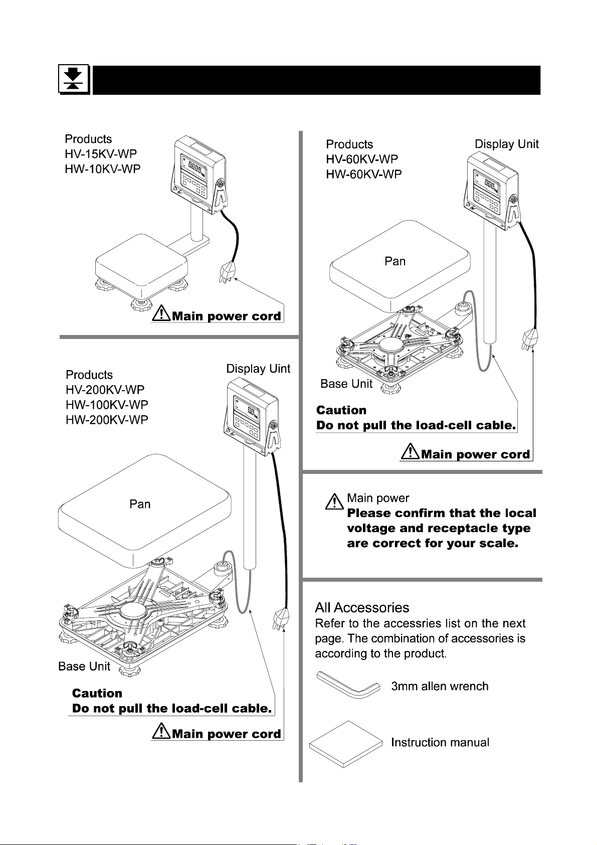
HV-15KV-WP
HV-60KV-WP
HV-200KV-WP
HW-10KV-WP
HW-60KV-WP
HW-100KV-WP
HW-200KV-WP
WM : PD4000211A
Page 2

This is a hazard alert mark.
This mark informs you about the operation of the product.
Note This manual is subject to change without notice at any time to improve the product. No part
of this manual may be photocopied, reproduced, or translated into another language
without the prior written consent of the A&D Company.
Product specifications are subject to change without any obligation on the part of the
manufacture.
Page 3

Contents
1. Compliance........................................................................................ 3
1.1.1. Compliance with FCC rules.......................................................3
1.1.2. Classification of protection provided by enclosures...................3
2. Outline and Features.........................................................................4
3. Unpacking..........................................................................................5
3.1. Accessories and Options list..........................................................6
4. Caution..............................................................................................7
4.1. Precautions for Installing the Scale...............................................7
4.2. Precautions for Operating the Scale..............................................7
4.3. Precautions for Storing the Scale..................................................7
5. Installing the Scale.............................................................................8
5.1. Removing the pole.........................................................................9
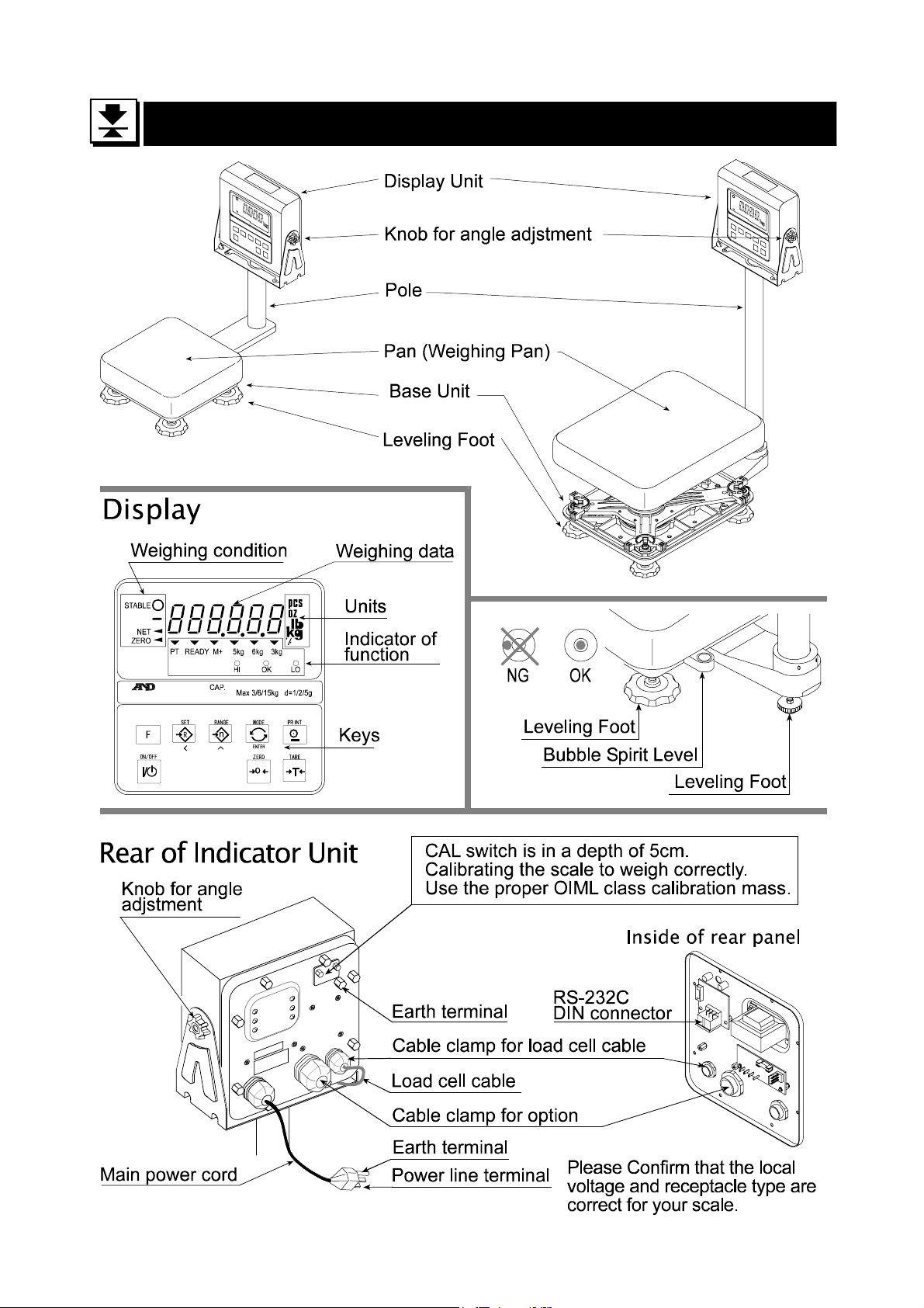
6. Names.............................................................................................11
6.1. Display and Symbols...................................................................12
6.2. Switches......................................................................................14
7. Basic Operation...............................................................................16
7.1. Turing the Scale on/off and Weighing..........................................16
7.2. Tare (And Net Display)................................................................17
7.2.1. The Way of Tare Input by Weighing........................................ 17
7.2.2. The Way of Digital Input (Preset Tare)....................................17
7.3. Weighing Range for the HV-WP series .......................................18
7.4. Mode Switch (Changing Unit and Mode).....................................19
8. Counting Mode ................................................................................21
8.1. Storing a Unit Mass.....................................................................21
8.2. Counting the number of articles...................................................22
9. Percentage Mode............................................................................23
9.1. Storing a 100% Mass ..................................................................23
9.2. Reading percentage....................................................................24
10. Accumulation Function .................................................................... 25
10.1. Preparation (Setting Parameters)................................................26
10.2. Operation and Performance (Examples).....................................27
11. Upper/Lower Comparator Function..................................................28
11.1. Preparation (Setting Parameters)................................................29
11.2. Operation and Performance (Examples).....................................31
12. Full/Dribble Batch Function..............................................................32
12.1. Preparation (Setting Parameters)................................................34
13. Simple Batch Function.....................................................................36
©A&D Co. ltd., HV-WP/HW-WP Series Instruction Manual
International Version 1895-2A-IE 0011
Page 4

13.1. Preparation (Setting Parameters)................................................37
13.2. Operation and Performance (Examples).....................................38
14. Calibration (Adjusting the Scale)......................................................39
14.1.1. The Gravity Acceleration Table...............................................40
14.2. The Complete Calibration Procedure ..........................................41
14.2.1. Gravity Acceleration Correction...............................................41
14.2.2. Preparation..............................................................................41
14.2.3. Calibration of the Zero Point....................................................42
14.2.4. Span Calibration......................................................................42
15. The Function Table..........................................................................43
15.1. The Procedure for Setting Paramet er s........................................43
15.2. Parameter List.............................................................................44
16. RS-232C Serial Interface.................................................................47
16.1. Data Format.................................................................................48
16.2. Stream Mode...............................................................................50
16.2.1. Preparation and Performance (Examples)..............................50
16.3. Command mode..........................................................................51
16.3.1. Command List.........................................................................51
16.3.2. Example of Setting Parameters...............................................54
17. Options............................................................................................55
17.1. Extension cable (OP-02) .............................................................55
17.2. RS-232C/ Relay output/ Buzzer (OP-03).....................................56
17.2.1. Installing OP-03....................................................................... 57
17.3. RS-422/ RS-485 / Relay output (OP-04) ..................................... 58
17.3.1. Installing OP-04....................................................................... 59
17.3.2. Communication Format........................................................... 60
17.3.3. Command List.........................................................................61
17.4. Roller Conveyor (OP-13, OP-14).................................................63
18. Specification ....................................................................................64
19. Maintenance....................................................................................68
19.1.1. Repair......................................................................................68
19.2. Check points Before Calling Maintenance Service......................68
Page 2 HV-WP/HW-WP Series
Page 5

1.
1. Compliance
1.1.
1.1.1.
1.1.1. Compliance with FCC rules
1.1.1.1.1.1.
1.1.2.
1.1.2. Classification of protection
1.1.2.1.1.2.
Compliance with FCC rules
Compliance with FCC rulesCompliance with FCC rules
Please note that this equipment generates, uses and can radiate radio frequency
energy. This eq uipment has be en tested and h as been fou nd to comply with the limits
of a Class A computing device pursuant to Subpart J of Part 15 of FCC rules. These
rules are designed to provide reasonable protection against interference when this
equipment is operated in a commercial environment. If this unit is operated in a
residential area it may cause some interference and under these circumstances the
user would be required to take, at his own expense, whatever measures are
necessary to eliminate the interference.
(FCC = Federal Communications Commission in the U.S.A.)
Classification of protection provided
Classification of protection Classification of protection
Compliance
ComplianceCompliance
provided by enclosures
providedprovided
by enclosures
by enclosures by enclosures
This equipment is designed to comply with the IP Code of IEC 529.
The "IP-65" code is explained as follows:
"IP" International Protection.
"6" Against ingress of solid foreign objects.
Dust-tight. No ingress of dust.
"5" Against ingress of water with harmful effects.
Protected against water jets (no powerful jets). Water projected in jets
against the enclosure from any direction shall have no harmful effects.
Compliance with European Directiv e
This appliance features radio interference suppression and safety of electrical
equipment designed for certain voltage in compliance with valid EC Regulation
89/366/EEC and 73/23/EEC.
Note: The displayed value may be adversely affected under extreme electromagnetic
influences.
HV-WP/HW-WP Series Page 3
2. Outline and Features
Page 6
2.
2. Outline and Feature
2.2.
These scales are designed to comply with IP-65 of IEC 529
The HV-WP series is a platform scale with 1/3000 resolution, and has a "triple
weighing range" function to select the weighing range.
The HW-WP series is a platform scale with 1/10000 resolution.
The scales have a fluorescent displ ay so the weig hing v alue can be read i n dim l ight.
This type uses the AC power line as a power source.
The counting mode function converts the total mass value (total weight) of articles to
be counted, to a count, when each of these articles assume the same mass value.
The scales can display the unit of percentage.
The accumulation functi o n acc um ul at es e ach weighing value and counts the number
of weighings using six figures.
The comparator function compares the display value with the upper limit value (HI),
lower limit value (LO) and displays the result. The result can be output if option OP03 is installed.
Outline and Featuressss
Outline and FeatureOutline and Feature
The simple batch function or full/dribble batch function can be used for filling up to a
target mass value. The status of a weighing value can be output if option OP-03 or
OP-04 is installed. The outputs are zero band, preliminary and Final.
Using the optional RS-422/RS-485 serial interface and a computer, up to 16 scales
can be controled, if this option is installed in place of the RS-232C serial interface.
The following parameters are stored in the product with no power supplied.
Unit mass of the counting mode
100% mass of the percentage mode
Total counts and total mass of the accumulation function
Upper limit value and lower limit value of the upper / lower comparator function,
Final value, preliminary value and zero band of the full / dribble batch function or
Final value, preliminary value and zero band of the simple batch function
Calibration data
Parameters of the function table (f1 ~ f16)
2. Outline and Features
Page 4 HV-WP/HW-WP Series
Page 7
3.
3. Unpacking
3.3.
Unpacking
UnpackingUnpacking
HV-WP/HW-WP Series Page 5
3. Unpacking
Page 8
3.1.
3.1. Accessories and Options list
3.1.3.1.
Accessories and Options list
Accessories and Options listAccessories and Options list
Accessories for the HV-WP series and HW-WP series
Products Accessories
HV-15KV-WP
HW-10KV-WP
Instruction manual
A
A
HV-60KV-WP
HV-200KV-WP
HW-60KV-WP
HW-100KV-WP
HW-200KV-WP
Options List
OP-02 5m extension loadcell cable Tapping screw M4x10
OP-03 RS-232C interface/ Relay output/ Buzzer Connector JA:TCP0586
OP-04 RS-422/485 interface with relay output Connector TM:BLA9
OP-13 Roller conveyor for HV-200KV-WP, H W-100KV-WP and HW-200KV-WP
OP-14 Roller conveyor for HV-60KV-WP and HW-60KV-WP
A
A
3mm Allen wrench
Instruction manual
A
A
Cable or option name Accessories A
A
A
A
A
A
AX-KO577A RS-232C cable, D-sub 25 pin, 2m
AX-KO1786-200 RS-232C cable, D-sub 9 pin, 2m
A
A
3. Unpacking
Page 6 HV-WP/HW-WP Series
Page 9
4.
4. Caution
4.4.
4.1.
4.1. Precautions for Installing the Scale
4.1.4.1.
Ground the scale, so that the user will not be subjected to an electric shock.
Do not handle the Main power cord with wet hands.
The AC plug is not water-resistant. Install it in an area where it does no t get wet.
Do not install the scale where there is flammable or corrosive gas present.
Do not install the scale under water.
Do not pull, fold or arrange cables forcibly.
Consider the following conditions to get the most from your scale.
The best operation is wher e the temperature and r elative humidi ty are stable, the pl ace
to install the scale is a solid floor, there is no dr aft and th e power source is stable.
Do not install the scale in direct sunlight.
Do not install the scale near heaters or air conditioners.
Do not install the scale near equipment which produces magnetic fields.
Do not install the sc ale in a place where it is apt to be char ged with static electrici ty, or
where the relative humidity is lower than 45%RH. Plastic and isolators are apt to be
charged with static electricity.
Do not use an unstable power source.
Caution
CautionCaution
Precautions for Installing the Scale
Precautions for Installing the ScalePrecautions for Installing the Scale
4.2.
4.2. Precautions for Operating the Scale
4.2.4.2.
Periodically ensure that the weighing value is correct.
Calibrate the scale before using and after moving it to another location.
Do not place anything on the weighing pan which is heavier than the weighing capacity
Do not drop anything upon the weighing pan.
Do not use a sharp instr ument such as a pencil or ball-point pen t o press the switches.
Press the switches gently using only your finger.
We reccommend pressing the ZERO or TARE switch before each weighing to
prevent possible error.
4.3.
4.3. Precautions for
4.3.4.3.
Do not disassembol the scale.
Do not use solvents to clean the scale.
For best cleaning of the display unit, wipe with a dry lint free cloth or a lint free cloth
which is moistened with warm water and a mild detergent.
The base unit can be cleaned with gentle water jets while brushing the base unit.
Weigh only after the unit is dry.
Do not use a powerful water jet.
Precautions for Operating the Scale
Precautions for Operating the ScalePrecautions for Operating the Scale
Precautions for Storing
Precautions for Precautions for
Storing the Scale
StoringStoring
the Scale
the Scale the Scale
HV-WP/HW-WP Series Page 7
4. Caution
Page 10
5.
5. Installing the Scale
5.5.
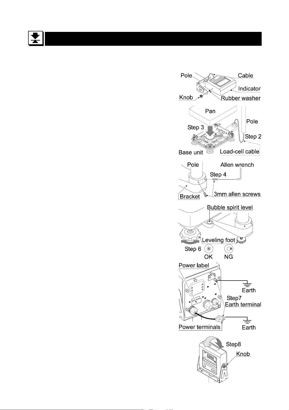
This procedure includes all of the steps for installing the HV-WP series and HW-WP
series. Therefore, on some products, there are some unnecessary steps.
Step 1 Connect the indicator unit to the pole with the
accesory knobs and rubber washers.
Step 2 Take the base unit and pole out, taking care
that the load-cell cable is not pulled.
Step 3 Put the weighing pan on the base unit.
Step 4 Insert the remainder of the load cell cable
into the pole. Attach the pole to the bracket
of the base unit s o as not to damage the load
cell cable. Affix the pole to the bracket using
Installing the Scale
Installing the ScaleInstalling the Scale
two 3mm Allen screws.
Step 5 Select the plac e for installing the scale. Also
consider "4. Caution" on page 7.
Step 6 Adjust the level of the base unit by using the
"Bubble spirit level" and "Leveling foot".
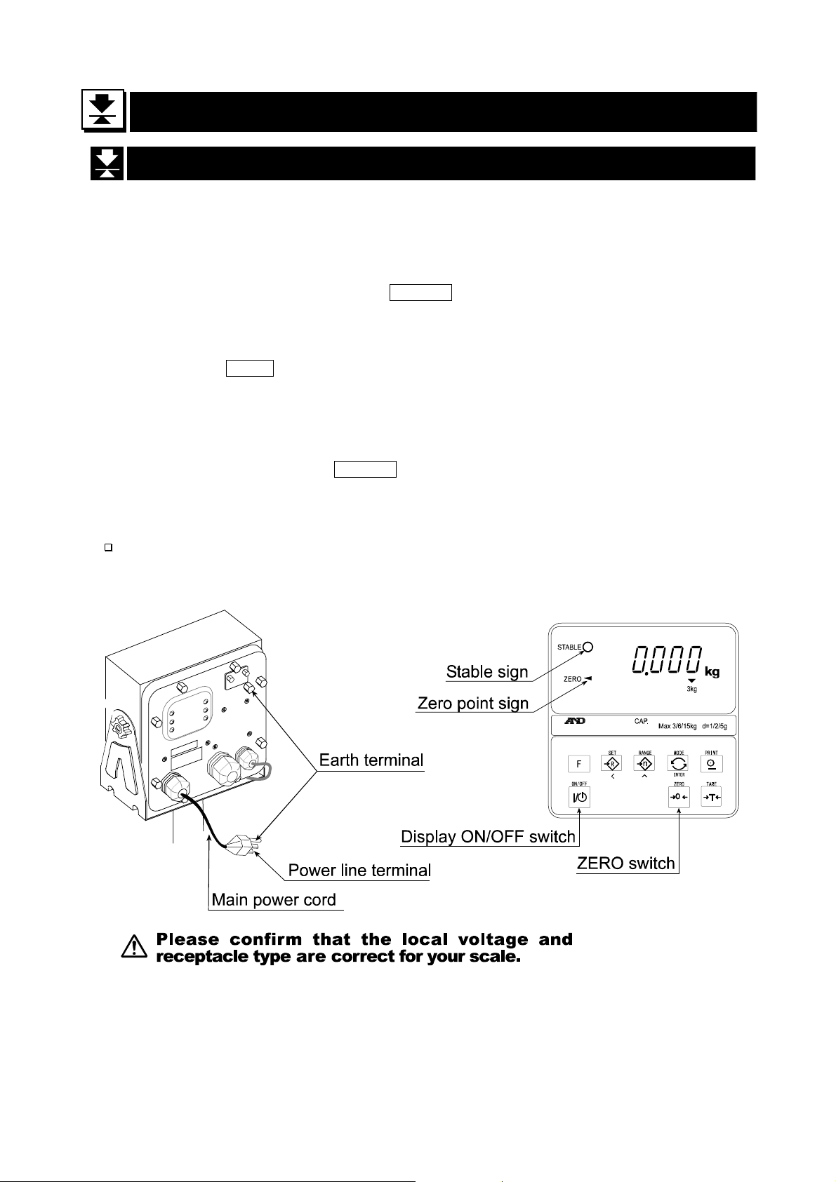
Step 7 Ground the scale using the earth terminal.
Caution
Please confirm that the local voltage and
the receptacle type are correct for your
scale.
Step 8 Adjust the angle of the indicator unit using
the knobs on the side of indicator unit.
Step 9 Check the weighing accuracy. If the scale
needs calibration, refer to "14. Calibration".
on page 39.
5. Installing the Scale
Page 8 HV-WP/HW-WP Series
Page 11
5.1.
5.1. Removing the
5.1.5.1.
Removing the pole
Removing the Removing the
pole
polepole
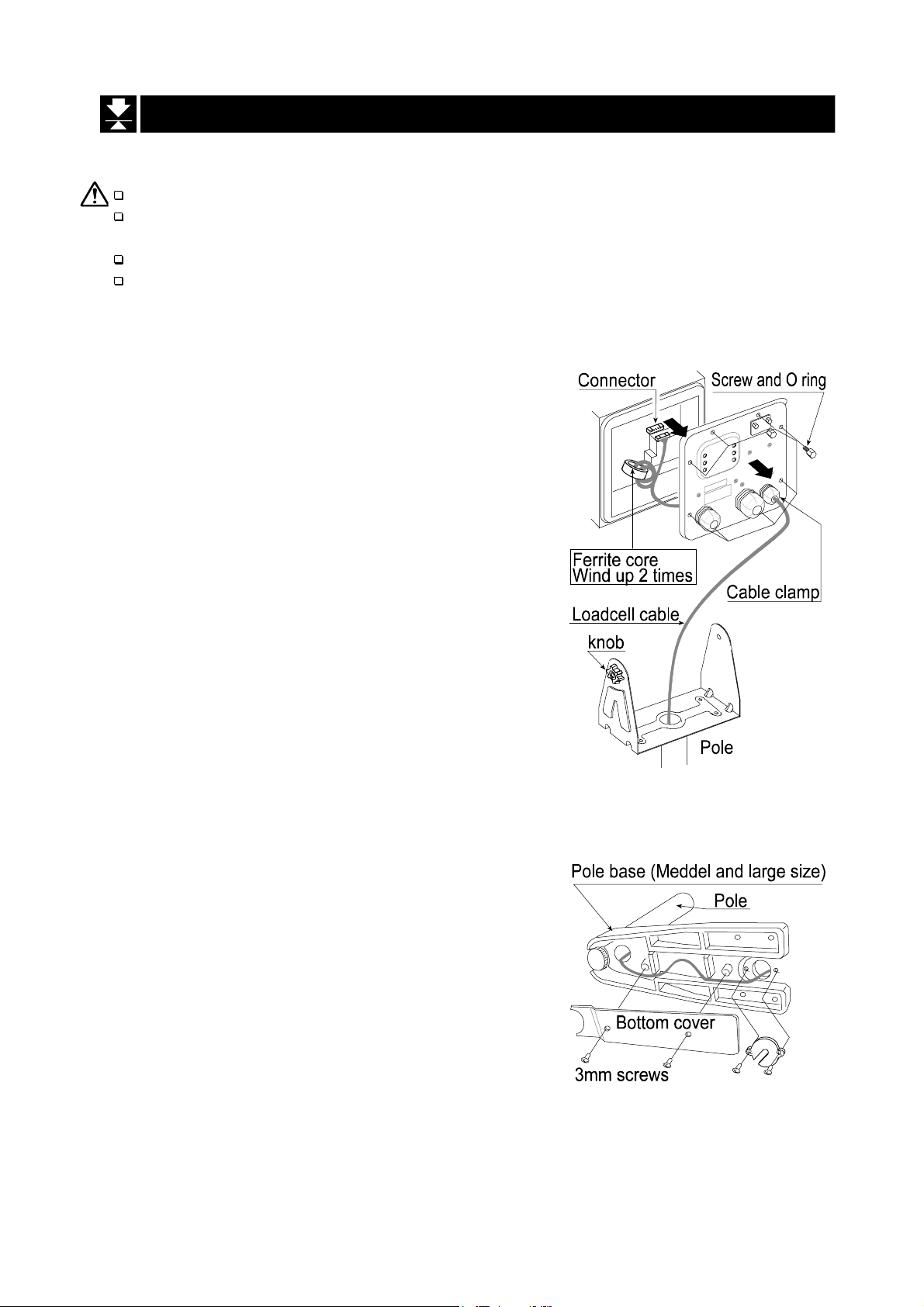
Caution
Remove the main power plug from the receptacle before removing the pole.
When removing the loadcell cable, do not pull the loadcell cable connector
forcibly and do not pull on the wires of the cable.
Do not bend the cable forcibly.
Avoid dust, static electricity and high humidity (or drops) because the inside
of the indicator unit is very sensitive.
Procedure
Step 1 Remove the power plug from the receptacle.
Step 2 Open the rear cover of indicator unit.
Disconnect the loadcell cable connector gently
(perpendicularly, do not pull to the side).
Step 3 Remove the ferrite core and cable clamp from
the loadcell cable.
Step 4 Loosen the knobs to remove the indicator unit.
Step 5 Remove four 3mm screws from the bottom of the
pole base for HV-60KV-WP, HV-200KV-WP,
HW-60KV-WP, HW-100KV-WP, HW-200KV-WP.
Step 6 Carefully remove the cable from the pole and
pole base. Especially, use care with the HV15KV-WP, HW-10KV-WP so that the co nnector
is not pulled forcibly.
Step 7 Arrange the cable so that it does not touch to
the weighing pan in the base unit. The untied
cable is at least 2m long. The optional
extension loadcell cable (OP-02) is 5m long.
HV-WP/HW-WP Series Page 9
5. 1. Removing the ploe
Page 12
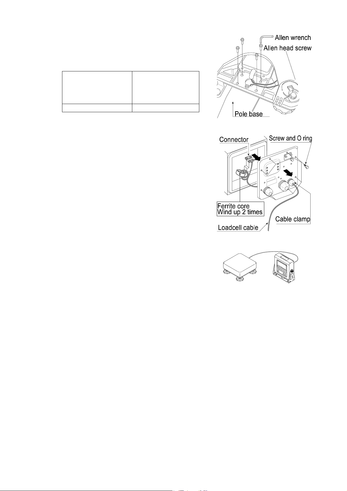
Step 8 Removing the pole base from the base unit ,
requires the following allen wrench.
HV-15KV-WP,
HV-60KV-WP,
HW-10KV-WP,
HW-60KV-WP
HV-200KV-WP,
HW-100KV-WP,
HW-200KV-WP
5mm Allen wrench 6mm Allen wrench
Step 9 Wind the cable through the ferrite core two
times. Affix the cable to the rear cov er using the
cable clamp.
Step10 Connect the cable to the connnector. Close the
rear cover.
Step11 Confirm the accuracy of the scale.
5. 1. Removing the ploe
Page 10 HV-WP/HW-WP Series
Page 13
6.
6. Names
6.6.
Names
NamesNames
HV-WP/HW-WP Series Page 11
6.Names
Page 14
6.1.
6.1. Display and Symbols
6.1.6.1.
Display and Symbols
Display and SymbolsDisplay and Symbols
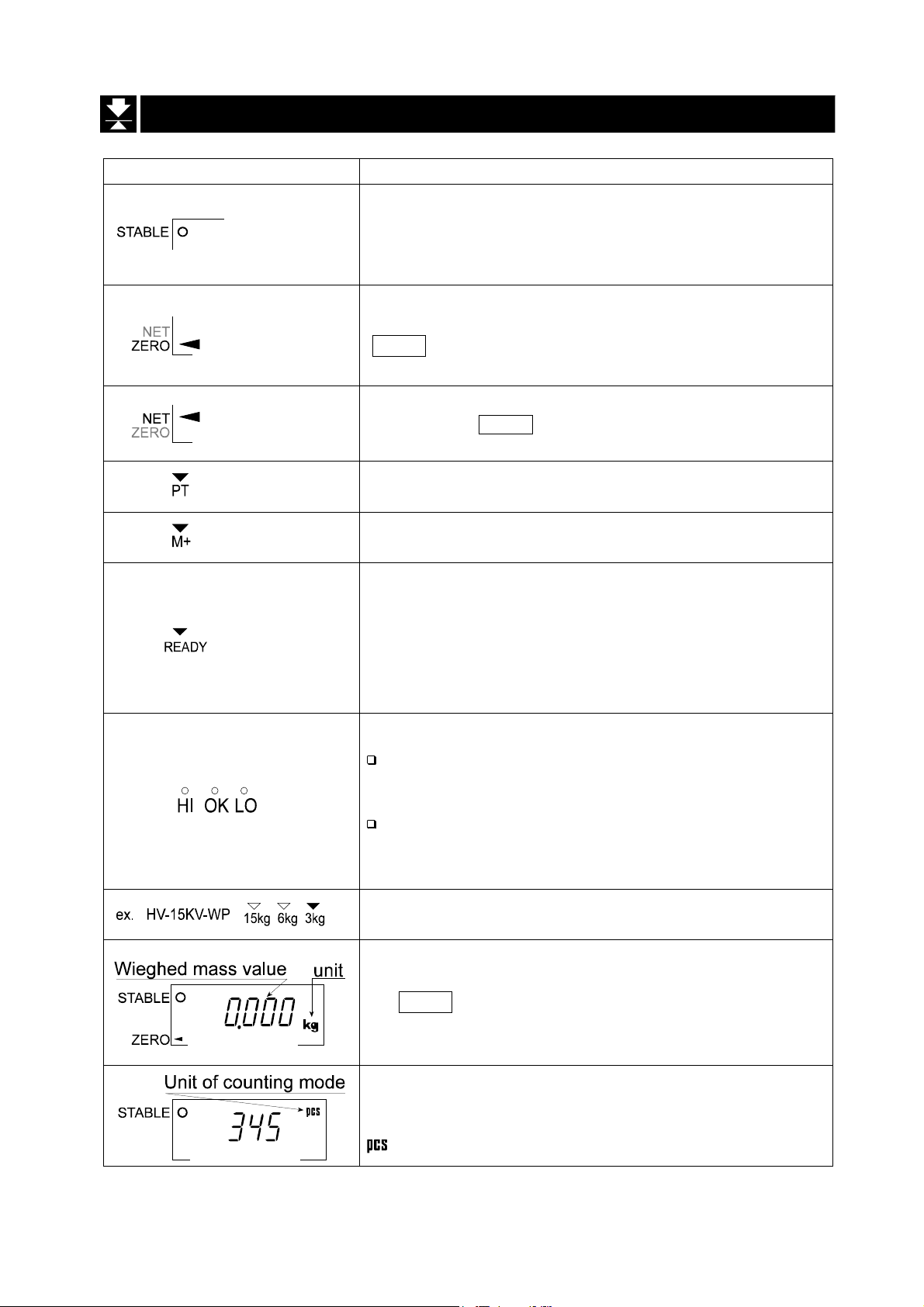
Display and Symbols Meaning
Stability mark.
When the cu rrent weighing va lue is stab le, this mark is
displayed, indicating a condition where the value is
readable.
Zero point mark.
With nothing on the weighing pan and pressing the
ZERO swi tch, this mark is displ ayed. The zer o point is a
fundamental starting point to weigh anything.
Net mark.
Pressing the TARE switch, this mark is displayed with
net display.
Preset tare mark.
Storing a tare with digital input, this mark blinks.
Accumulation mark.
Using the accumulation function, this mark is displayed.
Ready mark for the full/dribble batch function. The
meaning of th e mark is as follows:
ON The weighing value is within the zero-band.
OFF The full/dribble batch process is above the
zero-band.
Blinking The start or end of the full/dribble batch
process above the zero-band.
The comparator indicator.
Using the comparator function and comparing a
weighing value with the upper and lower limits, the
result is indicated.
Using the full/dribble batch function, the full flow
gate indicator is OK, the dribble flow gate indicator
is HI and the zero band indicator is LO.
The weighing range indicator for the HV-WP series.
The current range is indicated.
Example. Display of zero (zero point).
With nothing on the weighing pan and pressing
the ZERO switch, this mark is displayed.
The zero point mark is displayed.
The stability mark is displayed.
Example. Display of the counting mode.
This mode uses the registered unit mass, and counts
the amount of articles on the weighing pan. The unit is
.
A
A
A
A
A
A
A
A
A
A
A
A
A
A
A
A
A
A
A
A
A
A
A
A
A
A
A
A
A
A
A
A
A
A
A
A
A
A
A
A
6.1. Display and Symbols
Page 12 HV-WP/HW-WP Series
Page 15
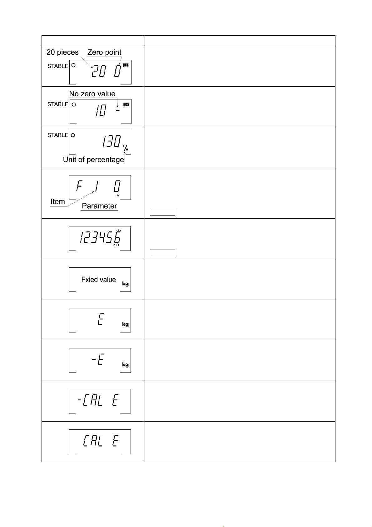
Display and Symbols Meaning
Example. Storing the unit mass of the counting mode.
This is a display of z ero point for the c ou nting mode an d
uses 20 pieces for the registration.
Example. Storing the unit mass of the counting mode.
The sign "-" means "weighing value is not zero".
Sample number is 10 pieces.
Example. Percentage mode.
This mode uses the registered 100% mass, and converts
the weighing value to a percentage. The unit is % .
Example. Display of the function table.
This function table sets parameters of items.
< switch Selecting an item.
∧ switch Selecting the paramete r of an item.
ENTER switch Storing new parameters.
Example. Preset tare. Entering tare with digital input.
< switch Selecting a figure.
∧ switch Selecting a number.
ENTER switch Storing a new tare.
Example. Hold display
The hold display is set using f12 of the function table.
When the va lue is "nearly-zero " or changes more than
25% +30 digits, the hold is canceled.
Over load display.
Remove the mass from the weighi ng pan.
Weighing error.
Check the base unit and weighing pan.
Calibration error.
The calibration mass is too light.
Check the base unit and weighing pan.
Calibration error.
The calibration mass is too heavy.
Check the base unit and weighing pan.
A
A
A
A
A
A
A
A
A
A
A
A
A
A
A
A
A
A
A
A
A
A
A
A
A
A
A
A
A
A
A
A
A
A
A
A
A
A
A
A
A
A
The " nearly-zero " is within ±4 digits from zero point in the unit of kg.
HV-WP/HW-WP Series Page 13
6.1. Display and Symbols
Page 16
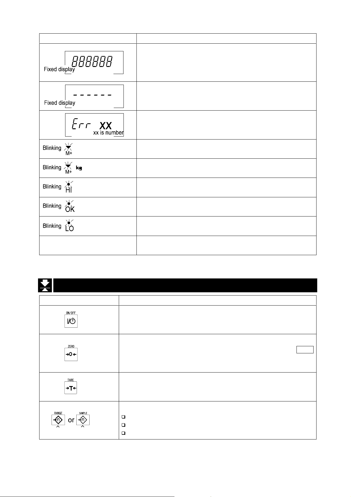
Display and Symbols Meaning
An error where the weighing value is unstable due to
drift, vibration or other, when turning on the scale.
Check around the weighing pan.
Check the connection of load cell cable.
Remove anything that may be on the weighing pan.
Check around weighing pan.
Perform zero point calibration of the scale.
Error indication.
Refer to "19 Maintenance".
Accumulated data count.
Total mass value of the accumulated data.
Comparator function, display is an upper limit.
Full/dribble batch function, t he displ ay is a final value .
Full/dribble batch function, the display is a preliminary
value.
Comparator function, display is a lower limit.
Full/dribble batch function, the display is the zero band.
CAP. MAX. 3/6/15kg d=1/2/5 g
Description of the weighing unit, weighing range and
measurable minimum mass.
A
A
A
A
A
A
A
A
A
A
A
A
A
A
A
A
A
A
A
A
A
A
A
6.2.
6.2. Switches
6.2.6.2.
Display and Symbols Meaning
Switches
SwitchesSwitches
Display ON/ OFF switch.
Note Standby status when power is connected.
Zero switch.
When there is nothing on the weighing pan and the ZERO
switch is pressed, the scale displays the mass value of zero
and the zero point mark. Net is canceled, if it is displayed.
Tare switch.
Canceling the mass of a receptacle, case, bag, etc. which is
put on the weighing pan, and does not weigh its mass.
Range switch, Sample switch.
Changing weig hing range for HV-WP series.(Refer to f2 )
Storing the unit mass, it is used to select a sample number.
In the function table, it is used to select a parameter.
A
A
A
A
A
A
A
A
A
A
A
A
A
A
A
6.2. Switches
Page 14 HV-WP/HW-WP Series
Page 17
Display and Symbols Meaning
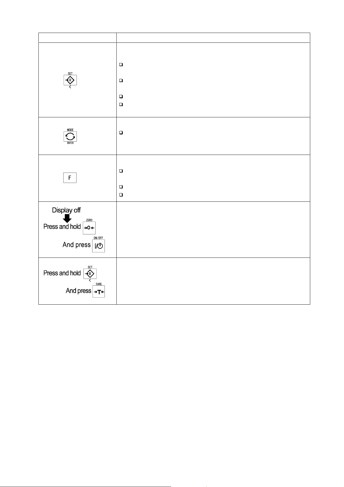
Set switch.
Turns the comparator on/off. (Refer to f6 )
Counting mode, it is used to enter the mode to store the
unit mass.
Percentage mode, it is used to enter the mode to store the
100% mass.
The full/dribble batch function, it is used as a start switch.
For the preset tare and selecting a calibration mass, it is
used to select a figure.
Mode switch.
Changing the current unit.
While setting modes, this switch is used for " storing a
parameter and proceeding to the next step".
F switch.
Full/dribble batch function, it is used to finish the process.
(Refer to f10 )
Hold switch. (Refer to f12 )
Setting a preset tare, selects polarity (+,-).
Used to enter the function table.
Used to enter the mode to set a preset tare.
A
A
A
A
A
A
A
A
A
A
A
A
A
A
A
A
A
A
A
A
A
A
A
A
A
A
A
A
A
HV-WP/HW-WP Series Page 15
6.2. Switches
Page 18
7.
7. Basic Operation
7.7.
7.1.
7.1. Turing
7.1.7.1.
Step 1 Ground the scale using the earth terminal.
Step 2 Place nothing on the weighing pan.
Step 3 Confirm that local voltage and receptacle type adapt to your scale.
Step 4 The scale turns on/off using the ON/OFF switch alternately.
Step 5 Check the accuracy of weighing. If you calibrate the scale, perform it after turning
the scale on for 30 minutes (warming up).
Step 6 Press the ZERO switch to display zero. (with nothing on the weighing pan.)
Step 7 Place an item on the weighing pan gently.
Step 8 You can read the mass value afte r the stability mark is displayed.
Step 9 Remove the item from the weighing pan.
Step10 Turn the scale using the ON/OFF switch off.
Basic Operation
Basic OperationBasic Operation
Turing the Scale on/off and Weighing
TuringTuring
the Scale on/off and Weighing
the Scale on/off and Weighing the Scale on/off and Weighing
Memo
With the power cord connected, the scale consumes only the power for standby
status after turning off the scale.
7. Basic Operation
Page 16 HV-WP/HW-WP Series
Page 19
7.2.
7.2. Tare (And Net Display)
7.2.7.2.
"Tare" is used to cancel the mass of a container, receptacle, case, bag, etc. which is
put on the weighing pan to contain the item to be weighed.
Tare (And Net Display)
Tare (And Net Display)Tare (And Net Display)
Caution
Using a tare value reduces the weighing range.
The current tare value is reset by pressing the ZERO switch or turning the
scale off. (Reset value is zero.)
The preset tare value must be within the minimum weighing range for the
HV-WP series.
7.2.1.
7.2.1. The Way of Tare Input by Weighing
7.2.1.7.2.1.
Step 1 Put the container item on the weighing pan.
Step 2 Press the TARE switch. The display becomes zero and the net mark is di spl ay ed.
The Way of Tare Input by Weighing
The Way of Tare Input by WeighingThe Way of Tare Input by Weighing
Step 3 It is now possible to put something into the container and to read its net display.
Step 4 Remove all things on the weighing pan.
7.2.2.
7.2.2. The Way of Digital Input (Preset Tare)
7.2.2.7.2.2.
Step 1 Press and hold the SET switch and press the TARE switch.
Step 2 Set the preset tare value by using the following switches.
Step 3 Press the ENTER switch to store the new preset tare value.
The Way of Digital Input (Preset Tare)
The Way of Digital Input (Preset Tare)The Way of Digital Input (Preset Tare)
Then the blank or stored tare value is displayed. A blank display means that the
tare value is zero (reset value), and or blinks.
∧ switc h Selecting the numbe r of the figure.
< switch Selecting a f igure.
F switch Selecting the polarity (+,-).
Then the scale displays a net value with the tare value subtracted from the gross
weighing value.
Step 4 It is then possible to put something into the container and to read its net.
Step 5 Remove all things from the weighing pan.
HV-WP/HW-WP Series Page 17
7. Basic Operation
Page 20
7.3.
7.3. Weighing Range for
7.3.7.3.
This is th e func tio n to s elec t a w eighi ng r ange for the HV-WP series.
The mass value is displayed within a selected range.
There is the automatic range (f2 0) and manual r ange (f2 1) using the RANGE switch.
Weighing Range for the
Weighing Range for Weighing Range for
Operation and Performance
Function table Meaning and purpose
Automatic range
The weighing range changes automatically, if the weighing
value proceeds from narrow range to wide range when
placing articles on the weighing pan.
f2 0
f2 1
When there is nothing on the weighing pan and t he z ero point
mark is displayed, it changes to the minimum range
automatically.
Press the ZERO switch to change to the minimum range,
when there is nothing on the weighing pan and the zero point
mark is not displayed due to net display or zero error.
Manual range
Press the RANGE switch to expand the range.
Press the RANGE switch to change to the minimum range,
when there is nothing on the weighing pan and the zero point
mark is displayed.
Press the ZERO switch and the RANGE switch to change to
the minimum range, when there is nothing on the weighing
pan and the zer o point mark i s not display ed due to net display
or zero error.
the HV-WP series
the the
HV-WP series
HV-WP seriesHV-WP series
A
A
A
A
A
A
A
A
A
A
A
A
A
A
A
A
A
A
A
Weighing Range
Products Weighing Range
HV-15KV-WP 3kg, 6kg, 15kg
HV-60KV-WP 15kg, 30kg, 60kg
HV-200KV-WP 60kg, 150kg, 220kg
7. Basic Operation
A
A
A
A
Page 18 HV-WP/HW-WP Series
Page 21
7.4.
7.4. Mode
7.4.7.4.
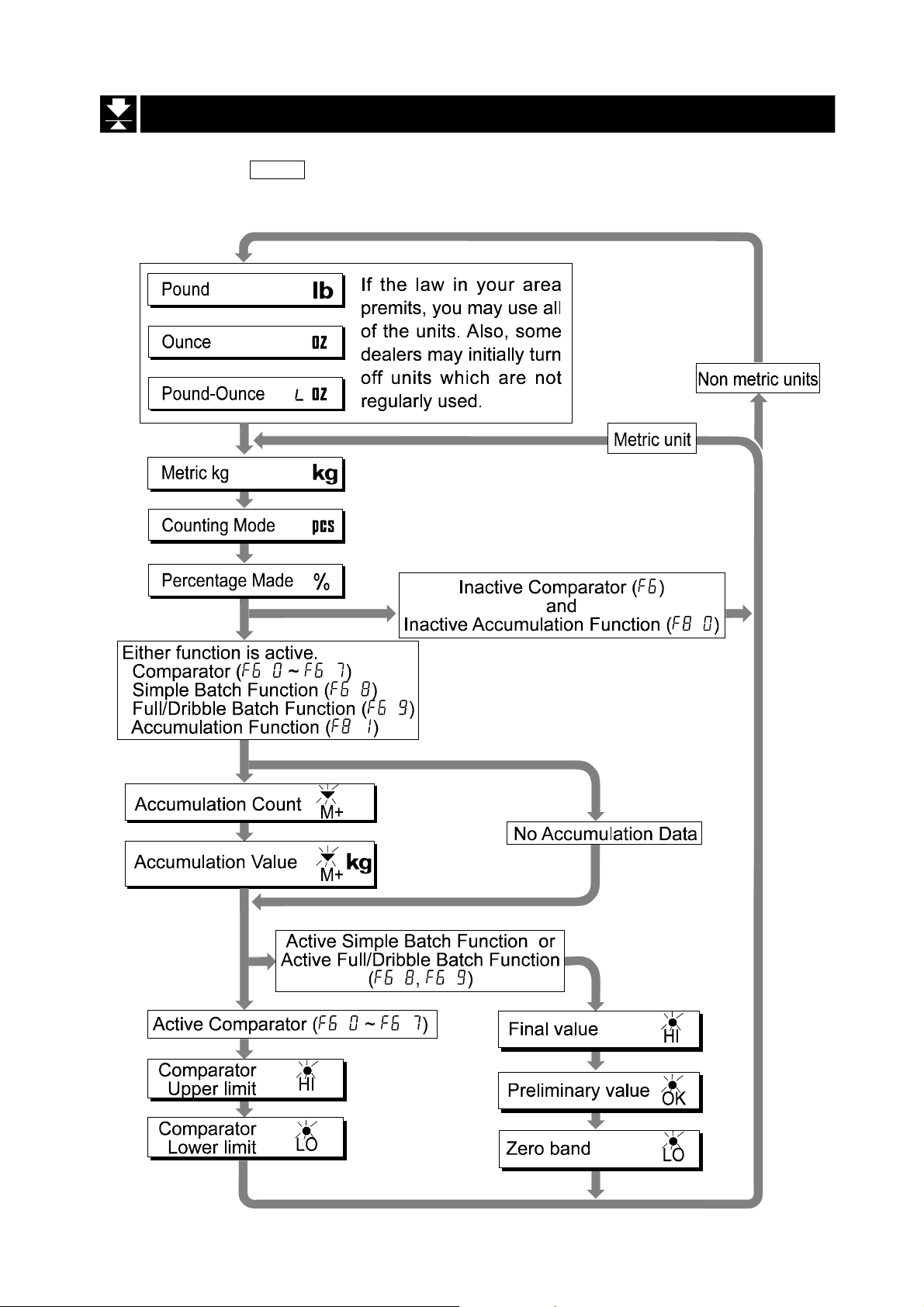
Pressing the MODE switch, the display changes as follows. Re fer to function table f3
for units. Usable units are according to the factory settings.
Mode Switch
Mode Mode
Switch (Changing Unit and Mode)
SwitchSwitch
(Changing Unit and Mode)
(Changing Unit and Mode) (Changing Unit and Mode)
HV-WP/HW-WP Series Page 19
7. Basic Operation
Page 22
Explanation
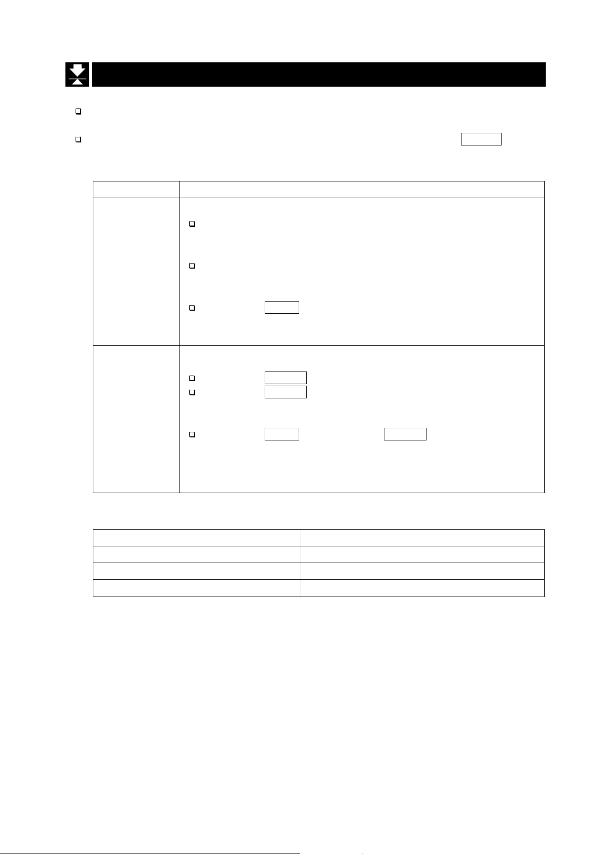
The status of "Inactive comparator (f6)" is that comparator function (f6 0, f6 2, f6 4, f6 6)
is selected and the comparator is not used. The "active" or "Inactive" (ON/OFF) for the
comparator can be selected by pressing the SET switch alternately.
The following parameters are stored in the same memory. Therefore, the functions
can not be used at the same time. If you use each function, it will be necessary to
select the function from the function tabl e, to set the par ameter s o f HI, OK and LO, to
weigh it using the function.
Memory address / Indicator and Output
HI OK LO
Upper/Lower Compar ator Function (f6 0 ~ 7)
Simple Batch Function (f6 8)
Full/ Dribble Batch Function (f6 9)
Upper limit Lower limit
Final value
Final value
Preliminary
value
Preliminary
value
Zero band
Zero band
7. Basic Operation
Page 20 HV-WP/HW-WP Series
Page 23

8.
8. Counting Mode
8.8.
The counting mode is the function to convert the total mass value (total weight) of
articles to a count, when each of these articles assume the same mass value.
It is necessary to store a unit mass to count articles.
8.1.
8.1. Storing a Unit Mass
8.1.8.1.
Step 1 Press the MODE switch to display the unit .
Step 2 Press the SET switch to enter the mode to store a
unit mass.
Step 3 Press the ∧ switch to select the number of
Counting Mode
Counting ModeCounting Mode
Storing a Unit Mass
Storing a Unit MassStoring a Unit Mass
samples. The greater the quantity of samples, the
greater th e accuracy of the c ount.
5 pieces, 10 pi eces, 20 pieces, 5 0 pieces, 100 piec es
Step 4 Put a container item on the weighing pan.
Press the TARE switch.
Step 5 Put in samples of number selected at step 3.
Press the ENTER switch to store it after the satbility
mark is displayed. Then the count is displayed.
Caution
When the sample is too light and it is not possibl e
to calculate a unit mass, the scale displays
and returns to step 3. It is nece ssary to have more
than 5 digits in the unit of kg to weigh a sample.
Pressing the ENTER switch after
displayed, the next unit is displayed.
When the unit mass is too light to store, the scale
displays
lo
lo ut .
lo lo
ut . .
ut .ut .
.
. .
lo
lo ut
lo lo
lo
lo ut
lo lo
ut .
ut ut
ut
utut
. is
..
Step 4 Remove all things from the weighing pan.
HV-WP/HW-WP Series Page 21
8. Counting Mode
Page 24

8.2.
8.2. Counting the number of
8.2.8.2.
Step 1 Press the MODE switch to display the unit .
Step 2 Store the articles unit mass.
Refer to "8.1 Storing a Unit Mass"
Step 3 Place the container item only on the weighing pan.
Press the TARE switch.
Step 5 Put articles in the container item and read the
count.
Counting the number of article
Counting the number of Counting the number of
articlessss
articlearticle
Step 6 Remove all things from the weighing pan.
8. Counting Mode
Page 22 HV-WP/HW-WP Series
Page 25

9.
9. Percentage Mode
9.9.
The percent mode is the function to display a mass value in the unit of "%".
Store a 100% mass value, in advance, to use this function.
9.1.
9.1. Storing a 100% Mass
9.1.9.1.
Step 1 Press the MODE switch to display the unit %.
Step 2 Press the SET switch to enter the mode that stores
a 100% mass.
Percentage Mode
Percentage ModePercentage Mode
Storing a 100% Mass
Storing a 100% MassStoring a 100% Mass
Step 3 With nothing on the weighing pan, press the ZERO
switch to display zero.
Step 4 Place the 100% mass on the weighing pan gently.
Press the
after the stability mark is displayed. Then the
percentage is displayed.
Caution
When the sample is too light and it is not possibl e
to calculate a 100% mass, the scale displays
and returns to step 3.
Pressing the ENTER switch after
the next unit is displayed.
ENTER switch, to store the 100% mass
lo .
lo
lo
is display ed,
lo lo
lo .
lo .lo .
Step 5 Remove all things from the weighing pan.
HV-WP/HW-WP Series Page 23
9. Percentage Mode
Page 26

9.2.
9.2. Reading percentage
9.2.9.2.
Step 1 Press the MODE switch to display the unit %.
Step 2 Store the unit mass of the article.
Refer to "9.1 Storing a 100% Mass "
Step 3 If a container is needed, place the tare item only
on the weighing pan and press the TARE switch.
Step 4 It is now possible to put something on the
weighing pan and read the percentage.
Reading percentage
Reading percentageReading percentage
Step 5 Remove all things from the weighing pan.
9. Percentage Mode
Page 24 HV-WP/HW-WP Series
Page 27

10.
10. Accumulation Function
10.10.
This function counts the number of weighed items, calculates the total mass value
and can display the number and accumulated mass value.
Set the parameters of the "accumulation function ( f8 )" in the function table, in
advance, to use this function.
Set the parameters o f the "pr int mode ( f9 )" in the function tabl e, in advance , to use
the built-in printer.
Accumulation Function
Accumulation FunctionAccumulation Function
Operation and Switches
The display of the accumulation count has a blinking without a unit.
The display of the accumulation value has a unit and a blinking .
Pressing the MODE switch, the accumulation count and accumulation value are
displayed.
Pressing the ZERO switch in the accumulation function ( is blinking), the current
function resets. (The count and accumulated value become zero.)
When the optional built-in printer is installed and the PRINT switch is pressed, the
accumulated data, date and data number are printed. The date is set at function table f16 .
Caution
The accumulation function can be used with the first weighing unit accumulated.
This function can display a maximum of six figures.
Parameter List and Word Definition
The "nearly-zero" is within ±4 digits from the zero point in the unit of kg.
The "digit", a unit of display, is equivalent to the minimum measurable mass.
The "zero point" is the fundamental starting point to weigh anything.
Function table Meaning and purpose
f8 0
f8 1
f8 2
f8 3
Accumulation function not used.
The scale accumulates the data, if the F switch is pressed, when
the display is a positive stable value without nearly-zero. The next
accumulation can be pe rformed after th e display i s nearly -zero or a
negative value.
The scale accumulates the data, if the F switch is pressed, when
the display is a stable value and without nearly-zero. The next
accumulation can be performed after the display is nearly-zero.
When the display is a positive stable value, the scale accumulates
the data automatically. The next accumulation can be performed
after the display is nearly-zero or a negative value.
A
A
A
A
A
A
A
A
A
A
A
A
HV-WP/HW-WP Series Page 25
10. Accumulation Function
Page 28
Function table Meaning and purpose
When the display is a stable value, the scale accumulates the data
automatically. The next accumulation can be performed after the
f8 4
f8 5
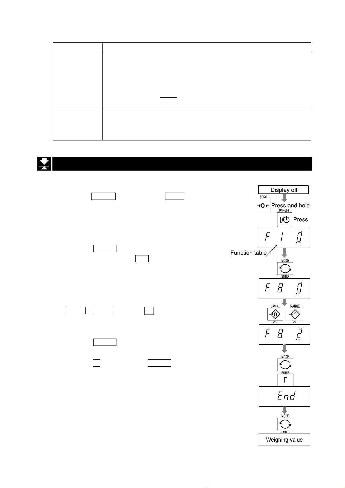
10.1.
10.1. Preparation (Setting Parameters)
10.1.10.1.
Step 1 Turn off the display.
Press the ON/OFF switch while the ZERO switch is
pressed and held. The function table is displayed.
display is nearly-zero.
Use Recording the number and mass of articles removed form
At each finish of the full/dribb le batch f unct ion, the sca le ac cumulates
the data automatically.
Use Packaging articles li ke a powder, it is used for recor ding the
Preparation (Setting Parameters)
Preparation (Setting Parameters)Preparation (Setting Parameters)
the weighing pan. (Put the articles on the weighing pan.
Press the TARE switch at each removal.)
bag number and total mass.
A
A
A
A
A
A
A
A
A
A
Step 2 Press the ENTER switch to display an item of the
accumulation function ( f8 ).
Step 3 Select a parameter of the accumulation func ti on
f8 1 ~ f8 4 ) with the ∧ switch.
(
Step 4 Press the
parameter.
Press the F switch and the ENTER switch to exit
from the function table. Then the scale di splays
the weighing mode.
ENTER switch to store the new
10. Accumulation Function
Page 26 HV-WP/HW-WP Series
Page 29

10.2.
10.2. Operation and Performance (Examples)
10.2.10.2.
Operation and Performance (Examples)
Operation and Performance (Examples)Operation and Performance (Examples)
Example 1
Weighing each article, the scale makes the accumulation according to f8 3 .
Step 1 Press the MODE switch to display .
Step 2 Press the ZERO switch to reset the accumulation data.
Step 3 Return to the kg mode using the MODE switch.
Press the ZERO switch with nothing on the weighing pan.
Step 4 Put an article on the weighing pan. Wait for the stability mark to be displayed and
the value to be blinking. Remove the article and press the ZERO switch.
Step 5 Weigh additional articles using step 4.
Step 6 Press the MODE switch to display the number of articles and total mass with .
Example 2
This example accumula tes the arti cles that were r emoved fro m the wei ghing pan. The
function parameter is set to f8 4 .
Step 1 Enter into the kg mode using the MODE switch.
Put all articles on the weighing pan and press the TARE switch.
Step 2 Press the MODE switch to display .
Step 3 Press the ZERO switch to reset the accumulation data.
Retun to kg mode with the MODE switch.
Step 4 Remove an article from the weighing pan. Wait for the stability mark to be
displayed and the value to be blinking. Press the TARE switch.
Step 5 Weigh additional articles using step 4.
Step 6 Press the MODE switch to display the number of articles and total mass with .
HV-WP/HW-WP Series Page 27
10. Accumulation Function
Page 30

11.
11. Upper/Lower Comparator Function
11.11.
This function compares a display value with the upper limit (HI), the lower limit (LO)
and displays the result.
Set the "comparator function ( f6 0 ~ f6 7 )" parameters, upper limit value (HI) and
lower limit value (LO) in the function table, in advance, to use this function.
Install option OP-03 or OP-04, to use the relay output of the comparator.
Install option OP-03, to use the buzzer output of the comparator.
Upper/Lower Comparator Function
Upper/Lower Comparator FunctionUpper/Lower Comparator Function
Comparator Sign
Comparison results are displayed by indicators .
Comparison Condition
Weighing value < lower limit value...................................LO is displayed and output.
Lower limit value≦ weighing v alue ≦ upp e r li m it v a lu e..OK is d is p la y e d and output.
Upper limit value< weighing value.....................................HI is displayed and output.
Parameter List and Word Definition
The " nearly-zero " is within ±4 digits from the zero point in the unit of kg.
The "digit", a unit of display, and is equivalent to the minimum measurable mass.
The "zero point" is the fundamental starting point to weigh anything.
Function table Meaning and purpose
f6 0
f6 1
f6 2
f6 3
f6 4
f6 5
f6 6
Pressing the SET switch, the scale always compares the current
display value.
The scale always compares the display value.
Pressing the SET switch, the scale always compares the display
value if not nearly-zero.
The scale always compares the di splay value if not nearly-zero.
When the display value becomes stable after pressing the SET
switch, the scale compares the display value. It does not compare on
an unstable condition. If the SET switch is presse d agai n, the s cal e
stops the comparison.
When the dis play value is st able, the sc ale compares th e display
value. It does not compare on an unstable condition.
When the display value becomes stable, while not nearly-zero,
after pr essing th e SET switc h, the scal e compa res th e displ ay val ue. I t
does not compare on an unstable condition. If the SET switch is
pressed again, the scale stops the comparison.
A
A
A
A
A
A
A
A
A
A
A
A
A
A
A
A
A
11. Upper/Lower Comparator Function
Page 28 HV-WP/HW-WP Series
Page 31

Function table Meaning and purpose
f6 7
When the disp lay value become s stable and not nea rly-zero, the
scale compares the value.
Caution
The upper limit value (HI) must be greater than the lower limit value (LO).
The parameters of the upper limit value (HI) and the final value (HI) use the
same memory. The parameters of the lower limit value (LO) and the zero band
(LO) use the same memory.
The upper/lower comparator function, the simple batch function and the
full/dribble batch function can not be used at the same time because these
parameters use common memory.
11.1.
11.1. Preparation (Setting Parameters)
11.1.11.1.
Step 1 Turn off the display.
Preparation (Setting Parameters)
Preparation (Setting Parameters)Preparation (Setting Parameters)
A
A
A
Press the
pressed and held. The function table is displayed.
Step 2 Press the ENTER switch to display an item of the
accumulation function ( f6 ).
Step 3 Select a parameter of the comparator function
( f6 0 ~ f6 7 ) with the ∧ switch.
Step 4 Press the ENTER switch to store the new param eter .
ON/OFF switch while the ZERO switch is
Step 5 Press the F switch and the ENTER switch to exit from
the function table. Then the scale displays the
weighing mode.
HV-WP/HW-WP Series Page 29
11. Upper/Lower Comparator Function
Page 32

Step 6 If either of f6 0 , f6 2 , f6 4 , f6 6 has been
selected, press the SET switch to use the
comparator.
Step 7 Press the MODE switch to display the blinking HI.
Step 8 Set the upper limit value by using the following
switches.
∧ switc h Selecting the number of a figure.
< switch Selecting a f igure.
F switch Selecting the polarity (+,-).
Step 9 Press the ENTER switch to store the new
parameter and display the blinking LO.
Step10 Set the lower limit value by using the follow i ng
switches.
∧ switc h Selecting the number of a figure.
< switch Selecting a f igure.
F switch Selecting the polarity (+,-).
Step11 Press the ENTER switch to store the new
parameters and display the weighing mode.
11. Upper/Lower Comparator Function
Page 30 HV-WP/HW-WP Series
Page 33

11.2.
11.2. Operation and Performance (Examples)
11.2.11.2.
Example 1
This example is set as follows:
Function table f6 3 (If the current display value is not nearly-zero,
Upper limit value (HI) 7.000kg
Lower limit value (LO) 6.500kg
Case
The comparison starts at turning the scale on.
When the current value is less than 6.500kg, LO is displayed.
When the current value is 6.500kg to 7.000kg, OK is displayed.
When the current value is greater than 7.000kg, HI is displayed.
Operation and Performance (Examples)
Operation and Performance (Examples)Operation and Performance (Examples)
the scale compares the display value with the
upper limit value and the lower limit value
immediately.)
Example 2
This example is set as follows:
Function table f6 4 (Pressing the SET switch, after the stability
mark is displayed, the scale compares the
current display v alue with the u pper limi t value
and the lower limit value immediately.)
Upper limit value (HI) 2.000kg
Lower limit value (LO) -1.000kg
Case
Pressing the SET switch, the comparison is p erformed after displaying th e stability
mark.
When the current value is less than -1.000kg, LO is displayed.
When the current value is -1.000kg to 2.000kg, OK is displayed.
When the current value is greater than 2.000kg, HI is displayed.
HV-WP/HW-WP Series Page 31
11. Upper/Lower Comparator Function
Page 34

12.
12. Full/Dribble Batch Function
12.12.
This function changes the scale to a filling machine which subdivides a bulk product
( like grain) into loads of predetermined and virtually constant mass.
Set the parameters of the "comparator function ( f6 9 )", " full/dribble batch subfunction ( f10 0 ~ f10 3 )" in the function table, final val ue (HI), preliminar y value (OK)
and zero band (LO), in advance, to use this function.
Install option OP-03 or O P-04, to use the relay output of the full/dribble batch functi on.
In case of building up a filling machine with a scale and hopper, the performance and
processing product of the system are assumed to be as follows:
Full/Dribble Batch Function
Full/Dribble Batch FunctionFull/Dribble Batch Function
Gross < Zero band
Net < Final - Preli minary
Final - Preliminary ≦ Net < Final
Final ≦ Net
12. Full/Dribble Batch Function
(Zero detection Level)
Zero band
indicator/
LO relay outp ut
ON / Make OFF / Break OFF / Break
OFF / Break ON / Make ON / Make
OFF / Break OFF / Break ON / Make
OFF / Break OFF / Break OFF / Break
Page 32 HV-WP/HW-WP Series
Preliminary value
indicator/
OK relay out put
Final value
indicator/
HI relay output
A
A
A
A
A
A
A
Page 35

Caution
The comparison of the full/dribble batch function is a one way sequence (not
reversible). If the display value becomes less than the final value after the
value reached a predetermined target value, neither HI or LO is on.
The parameters of the upper limit value (HI) and the final value (HI) use the
same memory. The parameters of the lower limit value (LO) and the zero band
(LO) use the same memory.
The upper/lower comparator function, the simple batch function and the
full/dribble batch function can not be used at the same time because these
parameters use common memory.
Set the zero band greater than the tare value.
Operation
Pressing the SET switch, the scale starts the batch process.
Selecting a parameter from f10 0 or f10 2 of the full/dribble batch su b-functi on, the
cF switch works as the finish switch.
Parameter List and Word Definition
The "gross" is a total weighing value where the tare value is not subtracted.
The "net" is a measurement value with the tare value subtracted from the gross.
The "zero band" is the zero detection level.
The "zero point" is the fundamental starting point to weigh anything.
Comparator
Function table Meaning and purpose
f6 9
Full/dribble batch sub-functi on
Function table Meaning and purpose
f10 0
f10 1
f10 2
f10 3
Hold
Function table Meaning and purpose
f12 0
Full/dribble batch function.
Reaching final value and pressing the
process is finished.
Reaching final value and displaying th e stability mark, the curren t
process is finished automatically.
Pressing the SET switch, the scale automatically tares and starts
the full/dribble batch process. Reaching final value and pressing
the F switch, the current process is finished.
Pressing the SET switch, the scale automatically tares and starts
the full/dribble batch process. Reaching final value and displaying
the stability mark, the current process is finished.
The hold function is not used.
F switch, the current
A
A
A
A
A
A
A
A
A
A
A
A
A
A
A
HV-WP/HW-WP Series Page 33
12. Full/Dribble Batch Function
Page 36

12.1.
12.1. Preparation (Setting Parameters)
12.1.12.1.
Step 1 Turn off the display.
Press the ON/OFF switch while the ZERO switch is
pressed and held. The function table is displayed.
Step 2 Press the ENTER switch to display an item of the
comparator function ( f6 ).
Step 3 Select a parameter of the full/dribbl e batch func ti on
( f6 9 ) with the ∧ switch.
Preparation (Setting Parameters)
Preparation (Setting Parameters)Preparation (Setting Parameters)
Step 4 Press the ENTER switch to store the new parameter
and display an item of the full/dribble batch subfunction ( f10 ) .
Step 5 Select a parameter of the full/dribble batch sub-
function ( f10 0 ~ f10 3 ) with the ∧ switch.
Step 6 Press the
Step 7 Press the
the function table. Then the scale displays the
weighing mode.
ENTER switch to store the new parameter
F switch and the ENTER switch to exit from
12. Full/Dribble Batch Function
Page 34 HV-WP/HW-WP Series
Page 37
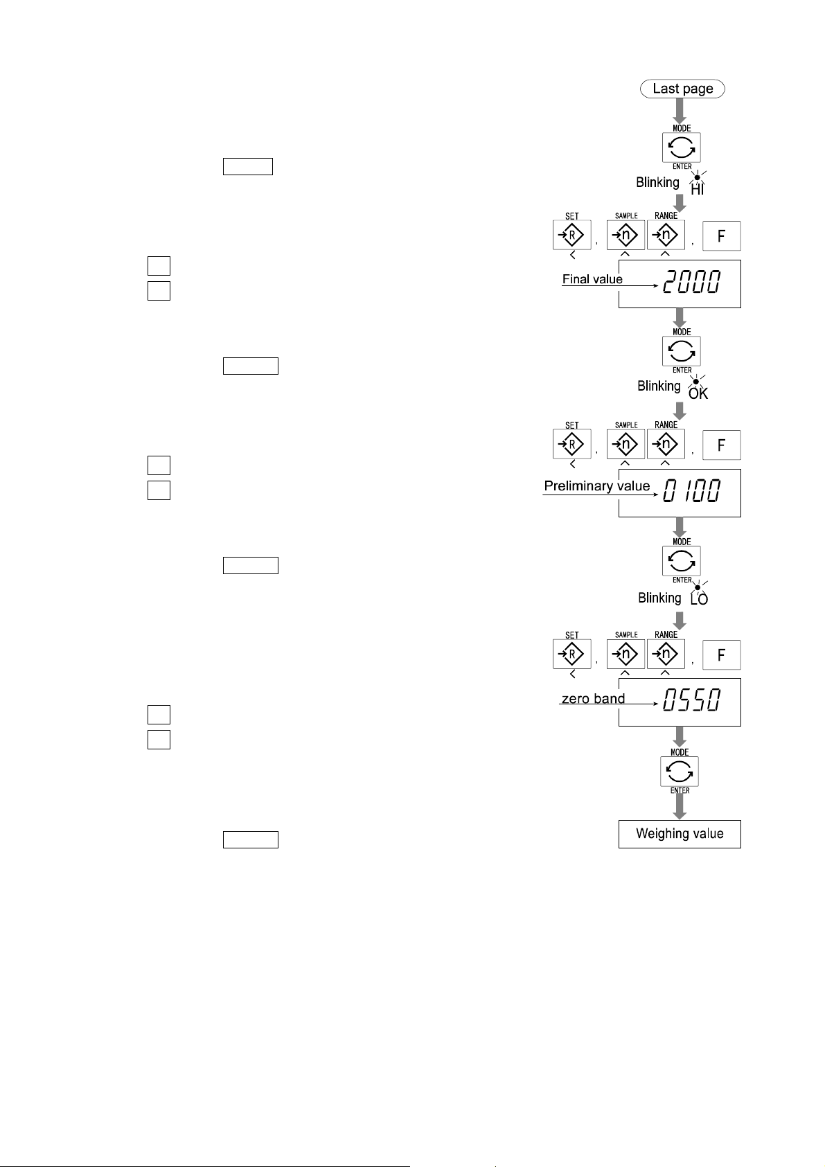
Step 8 Press the MODE switch to display the blinking HI (of
the final value).
Step 9 Set the final value using the following switches.
∧ switc h Sele cting the number of a figure.
< switch Selecting a figu re.
Step10 Press the ENTER switch to store the new parameter
and display the blinking OK (of preliminary value).
Step11 Set the preliminary value using the followi ng switches.
∧ switc h Sele cting the number of a figure.
< switch Selecting a figu re.
Step12 Press the ENTER switch to store the new parameter
and display the blinking LO (of zero band).
Step13 Set a zero band which is greater than the tare value,
using the following switches.
∧ switc h Sele cting the number of a figure.
< switch Selecting a figu re.
Step14 Press the ENTER switch to store the new parameter
and display the weighing mode.
HV-WP/HW-WP Series Page 35
12. Full/Dribble Batch Function
Page 38

13.
13. Simple Batch Function
13.13.
This function compaires a display value with the final value, preliminary value and
zero band for the full/dribble batch function. The result is indicated by zero band (LO
indicator), full flow (HI indicator) and dribble flow (OK indicator). Even if a weighing
value includes increase and decrease, this function can compare it.
Set the parameters of the "simple batch function ( f6 8 )", in the function table, final
value (HI), preliminary value (OK) and zero band (LO), in advance, to use this function.
Install option OP-03 or OP-04, to use the relay output of the comparison.
Install option OP-03, to use the buzzer output of the comparator.
Simple Batch Function
Simple Batch FunctionSimple Batch Function
Comparison Condition
Gross < Zero band.............. LO is displayed and output.
Final - Preliminary ≦ Net........................ OK is displayed and output.
Final ≦ Net........................ OK, HI is displayed and output.
Parameter List and Word Definition
The "gross" is a total measurement value where the tare value is not subtracted.
The "net" is a measurement value with a tare value subtracted from the gross.
The "tare" is an item put on the weighing pan and its mass is subtracted from the gross.
The "zero band" is the zero detection level.
The "zero point" is the fundamental starting point to weigh anything.
Function table Meaning and purpose
f6 8
13. Simple Batch Function
Simple batch function
Page 36 HV-WP/HW-WP Series
A
A
Page 39

Caution
The parameters of the upper limit value (HI) and a final value (HI) use the
same memory. The parameters of the lower limit value (LO) and the zero band
(LO) use the same memory.
The upper/lower comparator function, the simple batch function and the
full/dribble batch function can not be used at the same time because these
parameters use common memory.
13.1.
13.1. Preparation (Setting Parameters)
13.1.13.1.
Step 1 Turn off the display.
Press the ON/OFF switch while the ZERO switch is
pressed and held. The function table is displayed.
Preparation (Setting Parameters)
Preparation (Setting Parameters)Preparation (Setting Parameters)
Step 2 Press the ENTER switch to display an item of the
comparator function ( f6 ).
Step 3 Select a parameter of the simple batch function
( f6 8 ) with the ∧ switch.
Step 4 Press the ENTER switch to store the new parameter.
Step 5 Press the F switch and the ENTER switch to exit from
the function table. Then the scale displays the
weighing mode.
HV-WP/HW-WP Series Page 37
13. Simple Batch Function
Page 40

Step 6 Press the MODE switch to display the blinking HI (of
the final value).
Step 7 Set the final value using the following switches.
∧ switc h Sele cting the number of a figure.
< switch Selecting a figu re.
Step 8 Press the ENTER switch to store the new parameter
and display the blinking OK (of preliminary value).
Step 9 Set the preliminary value using the following switches.
∧ switc h Sele cting the number of a figure.
< switch Selecting a figu re.
Step10 Press the ENTER switch to store the new parameter
and display the blinking LO (of zero band).
Step11 Set the zero band using the following switches.
∧ switc h Sele cting the number of a figure.
< switch Selecting a figu re.
Step12 Press the ENTER switch to store the new parameter
and display the weighing mode.
13.2.
13.2. Operation and Performance (Examples)
13.2.13.2.
Step 1 Select the parameter f6 8 of the function table.
Operation and Performance (Examples)
Operation and Performance (Examples)Operation and Performance (Examples)
Step 2 Set the parameters of the final value, preliminary value and zero band.
Step 3 The comparison result is always displayed.
13. Simple Batch Function
Page 38 HV-WP/HW-WP Series
Page 41

14.
14. Calibration (Adjusting the Scale)
14.14.
The scale is an instrument w hic h measures the "w eig ht" and di splay s its "mass" val ue.
Calibration is the adjustment function so that the scale can weigh correctly.
There are three steps to calibration.
Gravity Acceleration Correction
Gravity Acceleration Correction ...When a ca librated sca le is move d to a d istant
Gravity Acceleration CorrectionGravity Acceleration Correction
Calibration of the Zero Point
Calibration of the Zero Point .........When there is nothing on the weighing pan, it is
Calibration of the Zero PointCalibration of the Zero Point
Span Calibration
Span Calibration ..............................The function that adjusts the span with a
Span CalibrationSpan Calibration
Calibration (Adjusting the Scale)
Calibration (Adjusting the Scale)Calibration (Adjusting the Scale)
place, the scale can correctly weigh anything
by revising to a new local gravity acceleration.
Refer to the "gravity acceleration table" on the
next page.
the function that performs adjustment so as to
display the zero point mark .
Comment The zero point, is the fundamen tal starting point
to weigh anything, influences the performance
of scale.
calibrated mass so the scale can accurately
weigh anything within the weighing capacity.
Comment Span means the range of weighing capacity.
Use a calibration mass heavier than two thirds
of the weighing capacity.
Caution
Calibrate the HV-WP series using a mass of the OIML class M1 or equivalent.
Calibrate the HW-WP series using a mass of the OIML class F2 or equivalent.
Periodically check the ac curacy of weighing. Calibrate th e scale, if it is mov ed
to another location or the environment has changed.
It is not necessary to set t he gravity acceleration correction, when c alibr at ing
the scale with a calibration mass at the place where the scale is to be used.
HV-WP/HW-WP Series Page 39
14. Calibration (Adjusting Scale)
Page 42

14.1.1.
14.1.1. The Gravity
14.1.1.14.1.1.
The Gravity AAAAcceleration
The Gravity The Gravity
cceleration Table
ccelerationcceleration
Table
Table Table
Amsterdam 9.813 m/s
Athens 9.800 m/s
Auckland NZ 9.799 m/s
Bangkok 9.783 m/s
Birmingham 9.813 m/s
Brussels 9.811 m/s
Buenos Aires 9.797 m/s
Calcutta 9.788 m/s
Chicago 9.803 m/s
Copenhagen 9.815 m/s
Cyprus 9.797 m/s
Djakarta 9.781 m/s
Frankfurt 9.810 m/s
Glasgow 9.816 m/s
Havana 9.788 m/s
Helsinki 9.819 m/s
Kuwait 9.793 m/s
Lisbon 9.801 m/s
London (Greenwich) 9.812 m/s
Los Angeles 9.796 m/s
Madrid 9.800 m/s
2
Manila 9.784 m/s
2
Melbourne 9.800 m/s
2
Mexico City 9.779 m/s
2
Milan 9.806 m/s
2
New York 9.802 m/s
2
Oslo 9.819 m/s
2
Ottawa 9.806 m/s
2
Paris 9.809 m/s
2
Rio de Janeiro 9.788 m/s
2
Rome 9.803 m/s
2
San Francisco 9.800 m/s
2
Singapore 9.781 m/s
2
Stockholm 9.818 m/s
2
Sydney 9.797 m/s
2
Taiwan 9.788 m/s
2
Taipei 9.790 m/s
2
Tokyo 9.798 m/s
2
Vancouver, BC 9.809 m/s
2
Washington DC 9.801 m/s
2
Wellington NZ 9.803 m/s
2
Zurich 9.807 m/s
2
2
2
2
2
2
2
2
2
2
2
2
2
2
2
2
2
2
2
2
2
14. Calibration (Adjusting Scale)
Page 40 HV-WP/HW-WP Series
Page 43

14.2.
14.2. The
14.2.14.2.
14.2.1.
14.2.1. Gravity Acceleration Corr
14.2.1.14.2.1.
Step 1 Turn on the display.
Open the cover of the display unit.
Press and hold the CAL switch, it is in the depth of
5cm, to enter the calibration mode.
Then Cal 0 is displayed.
Step 2 Press the ZERO switch to enter the gravity
acceleration correction mode.
The Complete
The The
Gravity Acceleration Correction
Gravity Acceleration CorrGravity Acceleration Corr
Complete Calibration Procedure
CompleteComplete
Calibration Procedure
Calibration Procedure Calibration Procedure
ction
ctionction
Step 3 Set your local gravity acceleration using the following
switches.
∧ switc h Sele cting the number of a figure.
< switch Selecting a figu re.
Step 4 Press the
Step 5 Press the CAL switch again. Then the scale retur ns to
the normal weighing mode.
14.2.2.
14.2.2. Preparation
14.2.2.14.2.2.
Step 6 Confirm the environment al condi ti ons as foll ows:
ENTER switch to store the new value.
Preparation
PreparationPreparation
Maintain a constant temperature and stable power.
Install the scale on a solid floor where there is no draft, vibration, strong magetic
fields or direct sunlight.
Consider section "4. Caution".
Step 7 Display normal weighing for at least 30 minutes to warm up the scale.
HV-WP/HW-WP Series Page 41
14. Calibration (Adjusting Scale)
Page 44

14.2.3.
14.2.3. Calibration of the Zero Point
14.2.3.14.2.3.
Step 8 Press and hold the CAL switch to enter
the calibration mode after displaying
normal weighing for 30 minutes.
Then Cal 0 is displayed
Step 9 With nothing on the weighing pan, press
the ENTER switch while the stable mark is
displayed. The scale stores the current
condition as the zero point.
Step10 The scale displays 5pn1 for several
seconds. Finishing the calibration mode
at this stage, proceed to step 14.
Calibration of the Zero Point
Calibration of the Zero PointCalibration of the Zero Point
14.2.4.
14.2.4. Span Calibration
14.2.4.14.2.4.
Step11 Set the value of the calibration mass
using the following switches. (This initial
value is according to each product.)
∧ switc h Sele cting the number of a
< switch Selecting a figu re.
Step12 Place the mass on the weighing pan
which was set at step 11, press the
ENTER switch while the stable mark is
displayed. The scale then calculates the
span and stores it.
Step13 The scale displays end at the finish.
Remove the mass from the weig hing pan.
Span Calibration
Span CalibrationSpan Calibration
figure.
Step14 Press the CAL switch to return to the normal
weighing mode.
14. Calibration (Adjusting Scale)
Page 42 HV-WP/HW-WP Series
Page 45

15.
15. The Function Table
15.15.
The function table is the function to store and refer items that determine the
performance of the scale. Each item has a parameter.
The parameters are maintained even without power applied.
15.1.
15.1. The Procedure
15.1.15.1.
Step 1 Turn off the display.
Press the ON/OFF switch while the ZERO switch i s
pressed and held. The function table is displayed.
The Function Table
The Function TableThe Function Table
The Procedure f
The ProcedureThe Procedure
for
or Setting Parameters
f f
Setting Parameters
oror
Setting Parameters Setting Parameters
Step 2 Set parameters for each item using the following
switches.
∧ switc h Sele cting the parameter of an item.
Selecting the number of a figure at f16.
< switch Selecting a figure at f16..
F switch Proceeding to the end of the table
without storing the parameter.
ENTER switch Storing a parameter for the current item
and proceeding to the next item.
Returning to normal mode from the end
of the table.
Step 3 Press the
when end is displayed.
ENTER switch to return to the normal mode,
Note Pressing the ENTER switch at step 2, the parameter is
stored in the scale.
HV-WP/HW-WP Series Page 43
15. The Function Table
Page 46

15.2.
15.2. Parameter List
15.2.15.2.
Parameter List
Parameter ListParameter List
Item Display Meaning and purpose
Automatic
display
OFF
Weighing
range
Unit
Baud rate
Output
mode
f1 0
f1 1
f2 0 # Automatic range
f2 1
f3 0 #kg
f3 1
f3 2
f3 3
f4 0 # 2400bps
f4 1
f4 2
f5 0 # Stream mode. (Refer to "16.2 Stream Mode")
f5 1
f5 2
f5 3
f5 4
f5 5
Turns the display OFF automatically.
No automatic display OFF
Automatic display OFF
Selects the way of changing weighing range for HV-WP series.
Manual range using the RANGE switch.
Selection of the first unit at the time when the scale turns on.
lb
oz
lb-oz
Transmission rate of the serial interface (RS-232C/ 422/485).
4800bps
9600bps
Mode selection for the serial interface (RS-232C/ 422/485).
Command mode. (Refer to "16.3 Command Mode")
Data is output, when the PRINT switch is pressed.
Auto-print +
When the display becomes a positive stable value without nearlyzero, the scale outputs the data automatically. Next output can be
performed after th e display becomes nearly-z ero or a negativ e value.
Auto-print +/When the display becomes a stable value without nearly-zero,
the scale outputs the data automatically. Next output can be
performed after the display becomes nearly-zero.
At each finish of full/dribble batch function, the data is output.
A
A
A
A
A
A
A
A
A
A
A
A
A
A
A
A
A
A
A
A
A
A
A
A
A
A
A
f6 0 #
f6 1
Comparator
The "#" is factory settings. The "nearly-zero" is within ±4 digits from zero point in the unit of kg.
15. The Function Table
f6 2
f6 3
f6 4
Pressing the SET switch, the scale always compares the current
display value.
The scale always compares the display value.
Pressing the SET switch, the scale always compares the display
value when not nearly-zero.
The scale always comp ares th e displa y value when not nearly-
zero.
When the display value becomes stable after pressing the
scale compares the display value. It does not compare on an unstable
condition. If the
SET
switch is pressed again, the scale stops the comparison.
Page 44 HV-WP/HW-WP Series
SET
switch, the
A
A
A
A
A
A
Page 47

Item Display Meaning and purpose
A
Comparator
Buzzer
Accumulation function
f6 5
f6 6
f6 7
f6 8
f6 9
f7 0 # No buzzer.
f7 1
f7 2
f7 3
f7 4
f7 5
f7 6
f7 7
f7 8
f8 0 # Accumulation function not used.
f8 1
f8 2
f8 3
f8 4
f8 5
When the display value becomes stable, the scale compares the
display value. It does not compare on an unstable condition.
When the display value becomes stable when not nearly-zero
after pr essing the SET switch, t he scale com pares the display value.
It does not compare on an unstab le condition. If the SET switch is
pressed again, the scale stops the comparison.
When the display value becomes stable when not nearly-zero,
the scale compares the value.
Simple batch function. (Refer to section 13.)
Full/dribble batch function. (Re fer to secti on 12.)
The condition of the buzzer on option OP-03 by comparator
function or full/dribble batch function.
The buzzer sounds at LO.
The buzzer sounds at OK.
The buzzer sounds at LO and OK.
The buzzer sounds at HI.
The buzzer sounds at LO and HI.
The buzzer sounds at OK and HI.
The buzzer sounds at LO, OK and HI.
The buzzer sounds at finishing the full/dribble batch process.
The condition of the accumulation function
The scale accumulates the data, if the F switch is pressed, when
the display becomes a positive stable value without nearly-zero.
Next accumulation can be performed after the display becomes
nearly-zero or a negative value.
The scale accumulates the data, if the F switch is pressed, when the
display becomes a stable value without nearly-zero. Next
accumulation can be performed after the display becomes nearlyzero.
When the display becomes a positive stable value, the scale
accumulates the data automatically. Next accumulation can be
performed after th e displ ay bec omes n ear ly-z ero or a neg ati ve v alu e.
When the display becomes a stable value, the scale ac cumulates
the data automatically. Next accumulation can be preformed after
the display becomes nearly-zero.
Use Recording number and mass of articles removed form the
weighing pan. (Put articles on the weighing pan. Press
TARE switch at each removal.)
At each finish of the full/dribble batch function, the scale
accumulates the data automatically.
Use Packing articles like a powder. used for recording the bag
number and total mass.
A
A
A
A
A
A
A
A
A
A
A
A
A
A
A
A
A
A
A
A
A
A
A
A
A
A
A
A
A
A
A
A
A
A
A
A
A
A
A
A
A
The "#" is factory settings. The "nearly-zero" is within ±4 digits from zero point in the unit of kg.
HV-WP/HW-WP Series Page 45
15. The Function Table
Page 48

Item Display Meaning and purpose
A
Full/Dribble
batch subfunc-tion
Address
Hold
Averaging
Precision
of unit
mass
Format
The details of the full/dribble batch function (f6 9)
f10 0 #
f10 1
f10 2
f10 3
f11 1 #
~
f11 99
f12 0 # Not used
f12 1
f12 2
f13 0 # Normal weighing.
f13 1
f13 2
f14 0 # Stores a unit mass in the unit of a digit.
f14 1
f14 2
f15 0 # Format 1. (A&D general format for scales, balances)
f15 1
f16
Reaching final value and pressing the F switch, the current
process is finished.
Reaching final value and displaying the stability mark, the current
process is finished automatically.
Pressing the SET switch, the scale automatically tares and starts
the full/dribble batch process. Reaching final value and pressing
the F switch, the current process is finished.
Pressing the SET switch, the scale automatically tares and starts
the full/dribble batch process. Reaching final value and
displaying the stability mark, the current process is finished.
Address for RS-422 / RS-485 for option OP-04
Use This address can be set from 01 to 99. It is possible for a
computer to control the scale assigned an address.
(RS-232C should be set to "00".)
The function to hold the current display value. When the value
becomes nearly-z ero and the weighing value chang es more tha n
25% +30 digits, hold display is canceled.
The hold function is ON or OFF alternately by the F switch. A
Displaying the stability mark, the display is held.
Selection of readability and response by averaging the weighing value.
Scale for a person’s weight.
Animal weighing.
Selects a storable minimum unit mass in the counting mode.
Stores a unit mass in the unit of one eighth digit.
Stores a unit mass, i f the tot al of th e sampl e mass i s greater than
5 digits.
Refer to "16.1. Data Format".
Format 2. (Older HV-A/ HW-A format)
Not used.
A
A
A
A
A
A
A
A
A
A
A
A
A
A
A
A
A
A
A
A
A
A
A
A
A
A
A
A
A
A
A
A
A
The "#" is factory settings
The "nearly-zero" is within ±4 digits from zero point in the unit of kg.
The "digit", a unit of display, is equivalent to the minimum measurable mass.
15. The Function Table
Page 46 HV-WP/HW-WP Series
Page 49

16.
16. RS-232C Serial Interface
16.16.
Note When the RS-232C serial interface is u se d, be sure to set the "Address ( f11 ) " to
"( 00 )".
The RS-232C interface has the following two modes.
Steam mode Outputs data countinuouslly and can be used for printing data.
Command mode Controls the scale using commads from a computer.
Set the parameters for the "Baud rate ( f4 )", " Output mode ( f5 )" and " Format
( f15 )", in the function table, in advance.
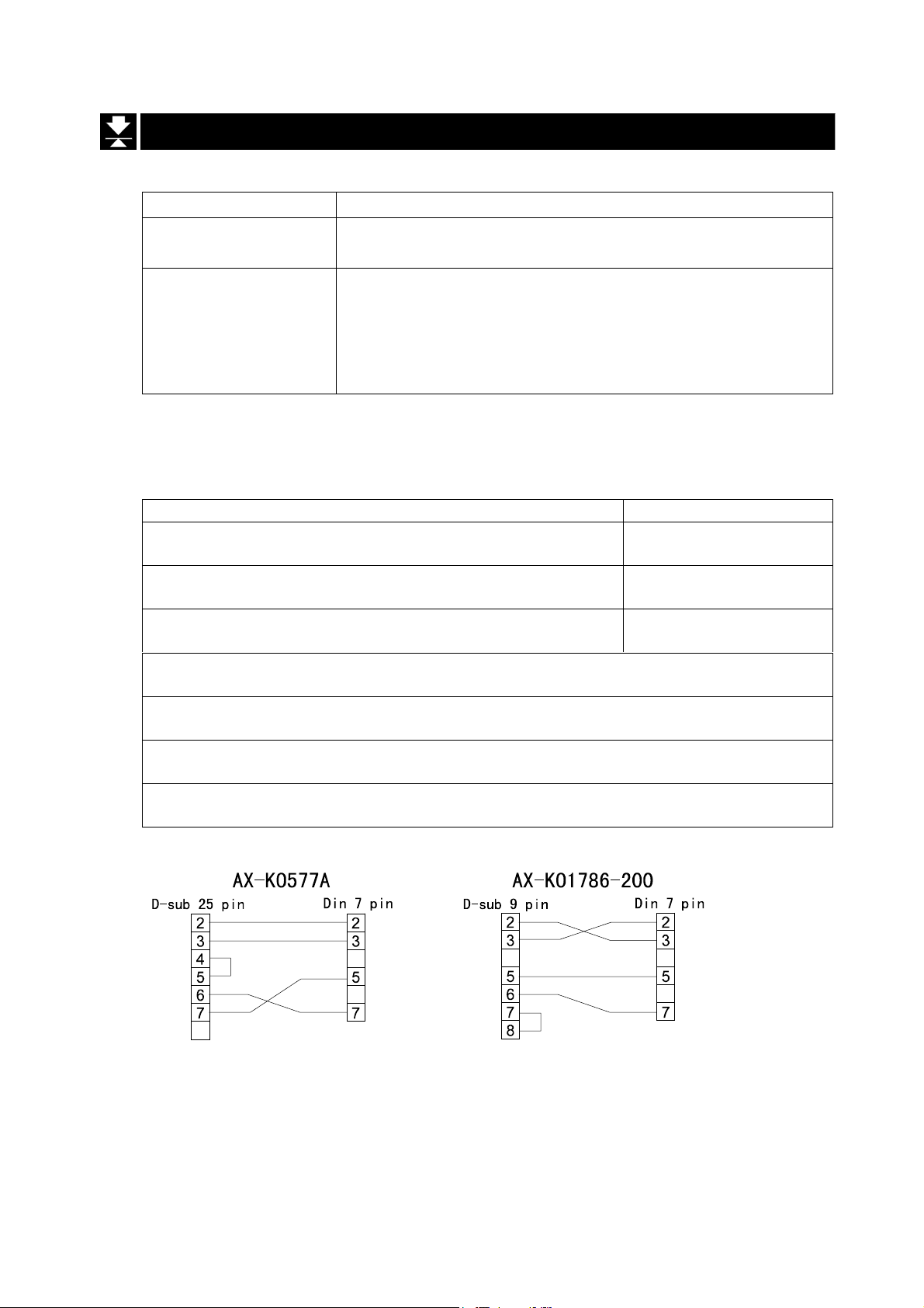
There are option cables as follows:
AX-KO577A RS-232C cable, D-sub 25 pin, 2m
AX-KO1786-200 RS-232C cable, D-sub 9 pin, 2m
Transmission system EIA RS-232C
Transmission Asynchronous, bi-directional, half-duplex
Data format Baud rate: 2400, 4800, 9600 bps
Pin connections
RS-232C Serial Interface
RS-232C Serial InterfaceRS-232C Serial Interface
Data: 7 bits
Parity: 1 bit, Even
Start bit 1 bit
Stop bit 1 bit
Code ASCII
Terminator CR LF (CR: 0Dh, LF: 0Ah)
Pin No. Signal name Direction Description
12 RXD Input Receive data
3 TXD Output Trans mi t dat a
45 SG - Signal ground
67 DSR Output Data set ready
A
A
A
A
A
A
A
A
Circuits
Adaptable connector DIN 7pin, (TCP0576)
HV-WP/HW-WP Series Page 47
16. RS-232C Serial Interface
Page 50

16.1.
16.1. Data Format
16.1.16.1.
Bit Format
Format 1
There are four headers for the type of data and weighing condition.
Stable weighing data Unstable weighing data
Stable counting data Out of range ( Over)
The weighing data consists of 9 characters including decimal point and polarity.
The polarity is always output.
Data Format
Data FormatData Format
There are three units. The unit is 3 characters.
In case of "out of range", numbers become all 9’s.
The terminator is always output as CR LF.
Data in the unit of kg
Counting mode
Percentage mode
Out of range
Definition of symbols
CR (carriage return) LF (line feed)
0Dh 0Ah
Space
20h
16. RS-232C Serial Interface
Page 48 HV-WP/HW-WP Series
Page 51

Format 2
There are four headers for the type of data and weighing condition.
Stable weighing data Unstable weighing data
Stable counting data Out of range
The weighing data consists of 7 characters including decimal point and polarity.
The data consists of 7 characters in the counting mode.
The polarity is always output.
There are three units. The unit is 2 characters.
In case of "out of range", numbers become all 9’s.
The terminator is always output as CR LF.
Caution
When the data is longer than 7 characters in the counting, precentage mode
or accumulation function, the overflow is ignored.
Data in the unit of kg
Counting mode
Percentage mode
Out of range
Definition of symbols
CR (carriage return)
0Dh 0Ah
Space
20h
LF (line feed)
HV-WP/HW-WP Series Page 49
16. RS-232C Serial Interface
Page 52

16.2.
16.2. Stream Mode
16.2.16.2.
The scale outputs the current display data at the time when refreshing the display.
The scale does not output data while in the setting mode.
Stream Mode
Stream ModeStream Mode
Averaging of function table Refresh rate
f13 0 Normal weighing
f13 1 A person’s weight
f13 1 Animal weighing
16.2.1.
16.2.1. Preparation and Performance (Examples)
16.2.1.16.2.1.
Step 1 Turn off the display.
Press the ON/OFF switch while the ZERO switch is
pressed and held. The function table is displayed.
Step 2 Select a parameter for the "ba ud rate ( f4 )" using
Preparation and Performance (Examples)
Preparation and Performance (Examples)Preparation and Performance (Examples)
Approximately 7 times/s while the display is unstable,
Approximately 4 times/s when the display is stable
Approximately 4 times/s
A
A
A
A
the ENTER and ∧ switches.
Step 3 Select "stream mode ( f5 0 )" of "output" using the
ENTER and ∧ switches.
Step 4 Select "format 1 ( f15 0
ENTER and ∧ switches.
Step 5 Press the ENTER switch to store the new
parameters. The scale re tur ns t he normal weighing
and outputs the data coutinuouslly.
)" of "format" using the
16. RS-232C Serial Interface
Page 50 HV-WP/HW-WP Series
Page 53
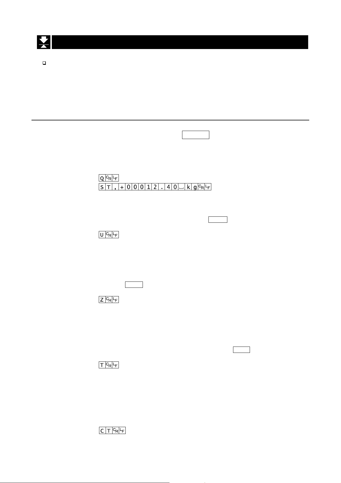
16.3.
16.3. Command mode
16.3.16.3.
The command mode is the function which can perform "output data", "controlling the
scale" and "setting parameters" by a command transmitted from a computer
Caution Allow at least 500 milliseconds between commands.
16.3.1.
16.3.1. Command List
16.3.1.16.3.1.
The following explanation uses "format 1 ( f15 0 )"
Command mode
Command modeCommand mode
Command List
Command ListCommand List
Data output
The current weighing data is output.
Template Q
Command
Reply
Selection of mode and unit
Selects the mode and unit. This is the same as the MODE switch.
Template U
Command
Reply The scale changes mode and unit.
Zero
The current mass value is set to the zero point.
This is the same as the ZERO switch.
Template Z
Command
Reply The mass value becomes zero and the zero point mark is displayed.
Tare
The current mass value is s et to zero a fter placing a tar e (contai ner, recept acle, case,
etc) and the net value is displayed. This is the same as the TA RE switch.
Template T
Command
Reply The current mass value becomes zero and the net mark is displayed.
Cancel of tare
The display value becomes the gross and the net mark is turned off. (The tare value
becomes zero.)
Template CT
Command
Reply Gross is displayed and the net mark is turned off.
HV-WP/HW-WP Series Page 51
16. RS-232C Serial Interface
Page 54

Preset tare
The tare value is set and the net value is displayed. The net mark is displayed.
Template PT, [parameter]
Command
Reply Net is displayed.
Upper limit value
An upper limit value is stored.
Template HI, [parameter]
Command
Reply The upper limit value is stored.
Lower limit value
A lower limit value is stored.
Template LO, [parameter]
Command
Reply The lower limit value is stored.
Caution The lower limit value must be less than the upper limit value.
Accumulation data output
The accumulated data is output.
Template A
Command
Reply
Accumulation count output
The number of accumulated data is output.
Template N
Command
Reply
Reset of Accumulation data and number
The data and number of accumulations become zero.
Template CA
Command
Reply The data and number of accumulations become zero.
16. RS-232C Serial Interface
Page 52 HV-WP/HW-WP Series
Page 55

Final value
The final value is stored.
Template S0, [parameter]
Command
Reply The value is stored.
Preliminary value
The preliminary value is stored.
Template S1, [parameter]
Command
Reply The value is stored.
Zero band
The zero band is stored.
Template S2, [parameter]
Command
Reply The value is stored.
HV-WP/HW-WP Series Page 53
16. RS-232C Serial Interface
Page 56

16.3.2.
16.3.2. Example of Setting Parameters
16.3.2.16.3.2.
Step 1 Turn off the display.
Press the ON/OFF switch while the ZERO switch is
pressed and held. The function table is displayed.
Step 2 Select a parameter for the "baud rate ( f4 )" using the
ENTER and ∧ switches.
Step 3 Select "command mode ( f5 1 )" for the "output"
using the ENTER and ∧ switches.
Example of Setting Parameters
Example of Setting ParametersExample of Setting Parameters
Step 4 Select "format 1 ( f15 0 )" for the "format" using the
ENTER and ∧ switches.
Step 5 Press the ENTER switch to store the new param eters.
Return to the normal weighing mode using the ENTER
switch.
Step 6 Receiving a command, the scale replies.
Page 54 HV-WP/HW-WP Series16. RS-232C Serial Interface
Page 57

This cable is used for installin g the indicator away from the base unit.
This loadcell cable is 5m long.
Refer to " 5.1. Removing Pole" for the way to remove the pole.
Caution
Calibrate the scale after connecting this cable.
Do not connect more than two extension cables.
17.
17. Options
17.17.
17.1.
17.1. Extension cable (OP-02)
17.1.17.1.
Options
OptionsOptions
Extension cable (OP-02)
Extension cable (OP-02)Extension cable (OP-02)
HV-WP/HW-WP Series Page 55
17.1. Extension cable (OP-02)
Page 58

17.2.
17.2. RS-232C/ Relay output/ Buzzer (OP-03)
17.2.17.2.
Note When the OP-03 is used, be sure to set the "Addre ss ( f11 ) " to "( 00 )".
This option replaces the RS-232C interface, refer to "16. RS-232C Serial Interface"
for specification of RS-232C.
The following option cables can be used, when you do not use the relay output.
RS-232C/ Relay output/ Buzzer (OP-03)
RS-232C/ Relay output/ Buzzer (OP-03)RS-232C/ Relay output/ Buzzer (OP-03)
Pin connections
Adaptable connector DIN 8pin, JA:TCP0586 (of accessory)
Circuits
Pin No. Signal name Direction Description
1 HI Output Relay output of HI
2 RXD Input Receive data
3 TXD Output Transmit data
4 LO Output Relay output of LO
5 SG - Signal ground (RS-232C)
6 OK Output Relay output of OK
7 DSR Output Data set ready
8 COM - Relay common terminal
A
A
A
A
A
A
A
A
A
Relay Solid-state-relay Maximum voltage DC50V
Maximum current DC100mA
Maximum resistance 8 Ω
17.2. OP-03, Options
Page 56 HV-WP/HW-WP Series
Page 59

17.2.1.
17.2.1. Installing the OP-03
17.2.1.17.2.1.
Caution Do not pull on the connected cables
while opening the rear panel.
Step 1 Remove the plastic panel from the option
board.
Step 2 Remove eight pairs of screws and O rings
from the indicator unit. Open the rear panel
of the unit.
Step 3 Remove the standard in terface board from
the indicator unit. Inst all the opti on board at
the same position.
Installing the OP-03
Installing the OP-03Installing the OP-03
Step 4 Connect the cable to the J1 connector on
the option board.
Step 5 Connect the DIN plug to the option board.
Ste p 6 Close and secure the rear panel using the
screws and O rings removed at step 2.
HV-WP/HW-WP Series Page 57
17.2. OP-03, Options
Page 60

17.3.
17.3. RS-422/ RS-485 / Relay output (OP-04)
17.3.17.3.
Replacing the RS-232C interface with this option, the RS-422/ RS-485 interface can
connect up to 16 scales and control them from a computer.
The RS-422/ RS-485 interface has the following two modes.
Steam mode Outputs data countinuouslly.
Command mode Controls the scale using commad from a computer.
Set the parameters for the "Baud rate ( f4 )", " Output mode ( f5 )" and " Format
( f15 )", in the function table, in advance.
Transmission system EIA RS-422/ RS-485
Transmission Asynchronous, bi-directional, half-duplex
Data format Baud rate: 2400, 4800, 9600 bps
RS-422/ RS-485 / Relay output (OP-04)
RS-422/ RS-485 / Relay output (OP-04)RS-422/ RS-485 / Relay output (OP-04)
Data: 7 bits
Parity: 1 bit, Even
Start bit 1 bit
Stop bit 1 bit
Code ASCII
Terminator CR LF (CR: 0Dh, LF: 0Ah)
Address 01 ~ 99 Address parameter ( f11 ) of the fu nction t able.
Relay Solid-state-relay
Maximum voltage DC50V
Maximum current DC100mA
Maximum resistance 8 Ω
Adaptable connector TM:BLA9 (of accessory)
Pin connections
Pin No. Signal name Direction Description
1 SDA Output RS-422/485 transmission A terminal
2 SDB Output RS-422/485 transmission B terminal
3 RDA Input RS-422/485 receive A terminal
4 RDB Input RS-422/485 receive B terminal
5TRM 6 HI Output Relay output of HI
7 OK Output Relay output of OK
8 LO Output Relay output of LO
9 COM - Relay common terminal
120Ω terminator
A
A
A
A
A
A
A
A
A
A
17.3. OP-04, Options
Page 58 HV-WP/HW-WP Series
Page 61
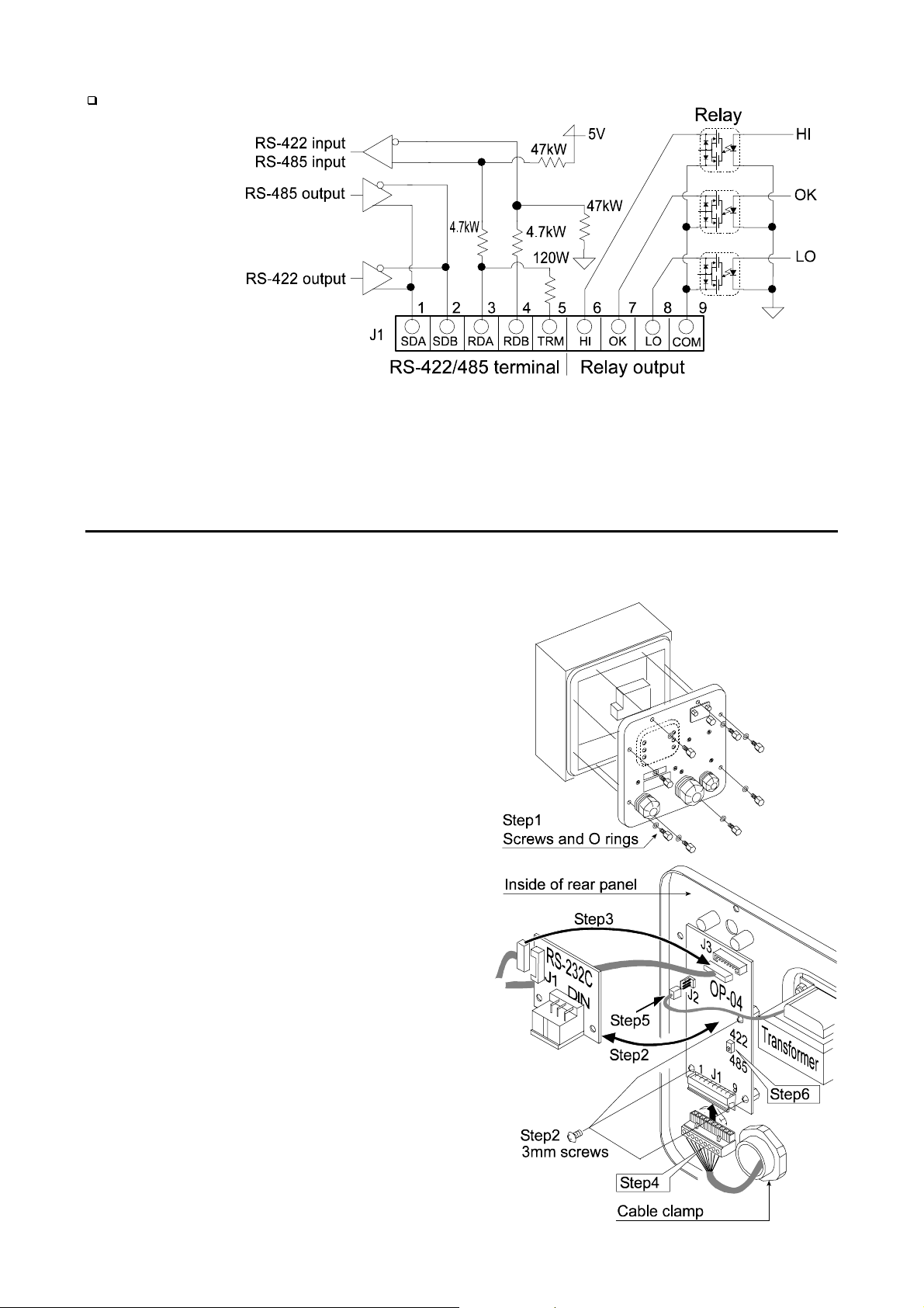
Circuits
Selection switch for the RS-422/ RS-485 interface
Selects either of RS-422 or RS-485 interface using a switch on the board.
17.3.1.
17.3.1. Installing the OP-04
17.3.1.17.3.1.
Installing the OP-04
Installing the OP-04Installing the OP-04
Caution Do not pull on the connected cables while opening the rear panel.
Step 1 Remove eight pairs of screws and O
rings from the indicator unit. Open the
rear panel of the unit.
Step 2 Remove the standard interface board
from the indicator unit. Install the
option board at the same position.
Step 3 Connect the cable to the J3 connector
on the option board.
Step 4 Wire the connector for J1 and connect
it to the option board.
Step 5 Connect a cable from the transformer
to the J2 connector.
Step 6 Set a interface type with the switch.
Step 7 Close and secure the rear panel using
the screws and O rings removed at
step 1.
HV-WP/HW-WP Series Page 59
17.3. OP-04, Options
Page 62

An example of connection
The polarities (A,B) of the
host computer signal
depends on the computer
model.
17.3.2.
17.3.2. Communication Format
17.3.2.17.3.2.
Commands consist of an address and the same command as for the RS-232C.
Commands return the same command when there is no data transmitted.
If the address is 23, the replay is as follows:
Normal response
Impossible command response
Undefined command response
Communication Format
Communication FormatCommunication Format
Bit format
17.3. OP-04, Options
Page 60 HV-WP/HW-WP Series
Page 63
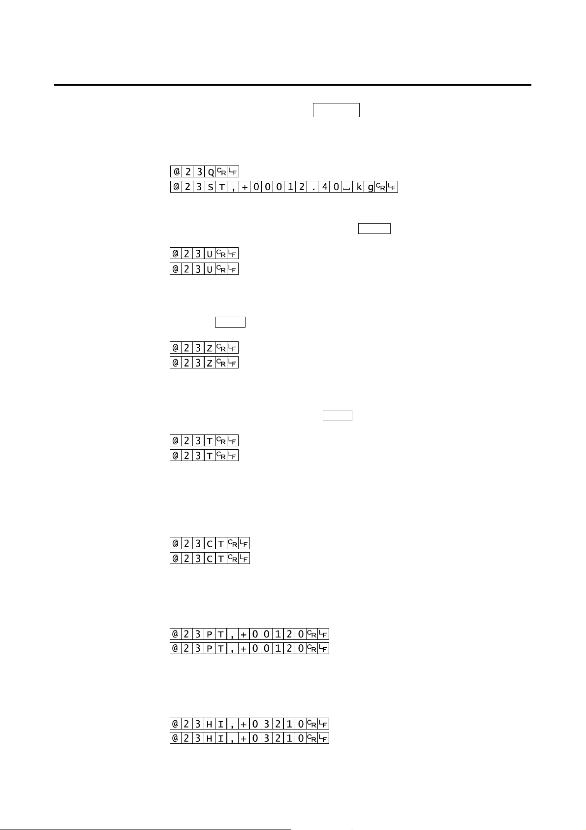
17.3.3.
17.3.3. Command List
17.3.3.17.3.3.
The following explanation uses "format 1 ( f15 0 )" assuming 23 as the address.
Command List
Command ListCommand List
Data output
The current weighing data is output.
Template Q
Command
Reply
Selection of mode and unit
Selects the mode and unit. This is the same as the MODE switch.
Template U
Command
Reply
The scale changes mode and unit.
Zero
The current mass value is set to the zero point.
This is the same as the ZERO switch.
Template Z
Command
Reply
The mass value becomes zero and the zero point mark is displayed.
Tare
The current mass value bec omes zer o after placing a tare (r eceptacl e, case, etc) and
the net is displayed. This is the same as the TARE switch.
Template T
Command
Reply
The current mass value becomes zero and the net mark is displayed.
Cancel of tare
The display value becomes the gross and the net mark is turned off. (The tare value
becomes zero.)
Template CT
Command
Reply
Preset tare
The tare value is set and the net value is displayed. The net mark is displayed.
Template PT, [parameter]
Command
Reply
Upper limit value
An upper limit value is stored.
Template HI, [parameter]
Command
Reply
Gross is displayed and the net mark is turned off.
Net is displayed.
The upper limit value is stored.
HV-WP/HW-WP Series Page 61
17.3. OP-04, Options
Page 64

Lower limit value
A lower limit value is stored.
Template LO, [parameter]
Command
Reply
The lower limit value is stored.
Caution The lower limit value must be less than the upper limit value.
Accumulation data output
The accumulated data is output.
Template A
Command
Reply
Accumulation count output
The number of accumulated data is output.
Template N
Command
Reply
Reset of Accumulation data and number
The data and number of accumulations become zero.
Template CA
Command
Reply
The data and number of accumulations become zero.
Final value
The final value is stored.
Template S0, [parameter]
Command
Reply
The value is stored.
Preliminary value
The preliminary value is stored.
Template S1, [parameter]
Command
Reply
The value is stored.
Zero band
The zero band is stored.
Template S2, [parameter]
Command
Reply
The value is stored.
17.3. OP-04, Options
Page 62 HV-WP/HW-WP Series
Page 65

17.4.
17.4. Roller Conveyor (OP-13, OP-14)
17.4.17.4.
Roller Conveyor (OP-13, OP-14)
Roller Conveyor (OP-13, OP-14)Roller Conveyor (OP-13, OP-14)
OP-13
This option can be used with the following products.
HV-200KV-WP,
HW-100KV-WP,
HW-200KV-WP
OP-14
This option can be used with the following products.
HV-60KV-WP,
HW-60KV-WP
HV-WP/HW-WP Series Page 63
17.4. OP-13, OP-14, Options
Page 66

18.
18. Specification
18.18.
Specification
SpecificationSpecification
HV-WP series
Product
Weighing Capacity [kg] 3 6 15 15 30 60 60 150 220
Min. weighing (1 digit) [g] 1 2 5 5 10 20 20 50 100
Weighing Capacity [lb] # 6 15 30 30 60 150 150 300 500
Min. weighing (1 digit) [lb] # 0.002 0.005 0.01 0.01 0.02 0.05 0.05 0.1 0.2
Weighing Capacity [oz] # 96 240 480 480 960 2400 2400 4800 8000
Min. weighing (1 digit) [oz] # 0.05 0.1 0.2 0.2 0.5 1 1 2 5
Weighing Capacity [lb_oz] # 30 lb
Min. weighing (1 digit) [lb_oz] # 0.1 oz
Number of samples in counting
mode [units]
Max. count number [units] 15,000 12,000 11,000
Display 7 segment fluorescent display, Character height 20mm
Repeatability [g] ±1 ±2 ±5 ±5 ±10 ±20 ±20 ±50 ±100
Linearity [g]
Span drift 20ppm/°C typ. (5°C ~ 35°C)
HV-15KV-WP HV-60KV-WP HV-200KV-WP
---
5(can be changed to 10、20、50、100)
±1 ±2 ±5 ±5 ±10 ±20 ±20 ±50 ±100
A
A
A
A
A
A
A
A
A
A
A
A
A
A
A
A
Power rating
Power source
Ambient temperature and hum idity - 10°C ~ 40°C, Less than 85%R.H. (Do not allow condensation)
Weighing pan size [mm] 250 x 250 330 x 424 390 x 530
Dimension [mm]
Width x Depth x Height
Mass of scale
[ kg ]
230V AC (+10%-15%) 50/60Hz 20VA, Fuse T200mA
or 120V AC (+10%-15%) 50/60Hz 20VA, Fuse T315mA
Please confirm that the loc al vol tage and recep tacle t ype are correct
for your scale.(50Hz/ 60Hz)
250 x 466 x 377 330 x 615 x 786 390 x 700 x 786
81319
# : If the law in your area allows, you can use these units.
A
A
A
A
A
A
A
18. Specification
Page 64 HV-WP/HW-WP Series
Page 67

HW-WP series
Product
Weighing Capacity [kg] 10 60 100 220
Min. weighing (1 digit) [g ] 1 5 10 20
Weighing Capacity [lb] # 20 150 200 500
Min. weighing (1 digit) [lb] # 0.002 0.01 0.02 0.05
Weighing Capacity [oz] # 320 2400 3200 8000
Min. weighing (1 digit) [oz] # 0.05 0.2 0.5 1
Weighing Capacity [lb_oz] # 20 lb
Min. weighing (1 digit) [lb_oz] # 0.1 oz
Number of samples in counting
mode [units]
Max. count number [units] 10,000 12,000 10,000 11,000
Display 7 segment fluorescent display, Character height 20mm
Repeatability [g]
Linearity [g] ±2 ±10 ±20 ±40
Span drift
HW-10KV-WP HW-60KV-WP HW-100KV-WP HW-200KV-WP
---
5(can be changed to 10、20、50、100)
±2 ±10 ±20 ±40
20ppm/°C typ. (5°C ~ 35°C)
A
A
A
A
A
A
A
A
A
A
A
A
A
A
A
A
Power rating
Power source
Ambient temperature and humidity
Weighing pan size [mm] 250 x 250 330 x 424 390 x 530 390 x 530
Dimension [mm]
Width x Depth x Height
Mass of scale
[ kg ]
230V AC (+10%-15%) 50/60Hz 20VA, Fuse T200mA
or 120V AC (+10%-15%) 50/60Hz 20VA, Fuse T315mA
Please confirm that the local voltage and receptacle type are correct for
your scale.(50Hz/ 60Hz)
-10°C ~ 40°C, Less than 85%R.H. (Do not allow condensation)
250 x 466 x 437 330 x 615 x 786 390 x 700 x 786 390 x 700 x 786
8 131919
# : If the law in your area allows, you can use these units.
A
A
A
A
A
A
A
HV-WP/HW-WP Series Page 65
18. Specification
Page 68

Dimensions
18. Specification
Page 66 HV-WP/HW-WP Series
Page 69

HV-WP/HW-WP Series Page 67
18. Specification
Page 70

19.
19. Maintenance
19.19.
Refer to "4. Caution" for use.
Refer to "6.1. Display and Symbols " and corresponding mode for displayed error code.
Refer to "14. Calibration (Adjusting Scale)" for precision weighing.
Periodically check the accuracy of weighing. Calibrate the scale, if it is moved to
another location or the environment has changed.
19.1.1.
19.1.1. Repair
19.1.1.19.1.1.
Do not disassemble/ assemble the scale without an auth orized service engineer. It may
cause an electric shock or damage to the scale, etc. In this case, repair is not covered
under warranty. Contact your l ocal A&D deal er if y our scal e needs ser vi ce or repair .
19.2.
19.2. Check points Before Calling Maintenance Service
19.2.19.2.
Maintenance
MaintenanceMaintenance
Repair
RepairRepair
Check points Before Calling Maintenance Service
Check points Before Calling Maintenance ServiceCheck points Before Calling Maintenance Service
In this situation Confirm these items
Nothing displayed.
Scale does not turn on.
The scale does not display
zero at first.
888888 is displayed and
does not proceed.
------ is displayed and
does not proceed.
Cal e is displayed
-Cal e is displayed
e is displayed
-e is displayed
Fixed display
err 1 is displayed
Is the AC power cord properly connected?
Is the AC power the correct voltage ?
Check around the weighing pan.
Is there anything on the weighing pan.
The weighing value is unstable due to drift,
vibration or other.
Check around the weighing pan.
Check the load cell cable connection.
Check around the w eighing pan. Remov e anythi ng
that is on the weighing pan.
Make zero point calibration of the scale.
Calibration error that meaning "Too heavy".
Calibration error that meaning "Too light".
Weighing error that meaning "Over load".
Weighing error that meaning "Under load".
Do you use the "hold function".
Turn off scale and it on.
It an error occurs. Contact yours local A&D dealer
to repair the product.
A
A
A
A
A
A
A
A
A
A
A
A
A
A
A
A
A
A
A
A
A
A
A
A
A
A
19. Maintenance
Page 68 HV-WP/HW-WP Series
Page 71

[ Blank page ]
ページ1
Page 72

4.34.25 E_]Wh^_.Fa[Xjajge- Peh^_cW.aj- Peane 281.1124 G>M>K
P[b[f^ed[; U92V +4, 64:2.7243 CWm; U92V +4, 64:2.7259
^iif;00lll/WWdZZ/Ye/`f0
tqv w}xy}ww+y}xr y}us
2666- JY@WdZb[hh Ag_k[- J_bf_iWh- @>/ :6146 Q/O/>/
P[b[f^ed[; U2V +519, 374.6444 CWm; U2V +519,374.122:
tqv y},-+.|w}-, {-vs
Qd_i 35037 ?bWYabWdZh RWn- >X_d]Zed ?jh_d[hh MWga- >X_d]Zed- Lmed LS25 2AT Qd_i[Z H_d]Zec
P[b[f^ed[; U55V +2346, 661531 CWm; U55V +2346, 661596
<x39708 ,1063: ~44513=
?[gd[g OigW [ 75- 71548 CgWda\jgi0JW_d 61 DBNJ>KT
P[b[f^ed[; U5:V +7:, 618.2128 CWm;U5:V +7:, 618.3165
tqv |w+u.+/ *-/s{-vs
43 A[l Oig[[i- P^[XWgied- Oeji^ >jhigWb_W 6142 >QOPN>IF>
P[b[f^ed[; U72V +9, 9463.4144 CWm; U72V +9, 9463.851:
tqv z~+wt {575;32
9i^ Cbeeg- JWd^WiiWd ?bZ]/ 47.3 Te_Ze.Zed]- Tejd]Z[jd]fe.aj- O[ejb- HLNB>
P[b[f^ed[; U93V +3, 891.5212 CWm; U93V +3, 893.5391
 Loading...