

Page 1

H
H
W
W--
G
G
S
S
e
errii
e
e
s
s
DDiiggiittaall PPllaattffoorrmm SSccaallees
s
Instruction Manual
0Z1M v1a
HW-10KGL HW-10KGV
HW-60KGL HW-60KGV
HW-100KGL HW100KGV
HW-200KGL HW-200KGV
Page 2
Page 3

Contents
1 Compliance........................................................................................3
1.1 Compliance with FCC rules ...........................................................3
2 Outline and Features .........................................................................4
3 Unpacking..........................................................................................5
3.1 Accessories and Options list .........................................................6
4 Caution ..............................................................................................8
4.1 Precautions for Installing the Scale ...............................................8
4.2 Precautions for Operating the Scale..............................................8
4.3 Precautions for Storing the Scale ..................................................8
5 Installing the Scale.............................................................................9
5.1 Installing the batteries for Type L ................................................11
6 Names .............................................................................................12
6.1 Display and Symbols ...................................................................13
6.2 Switches ......................................................................................15
7 Basic Operation ...............................................................................1 7
7.1 Turning the Scale on/off and Weighing .......................................17
7.1.1 Type V or Type L with AC adaptor ..........................................17
7.1.2 Type L with Batteries...............................................................18
7.2 Tare (and Net Display).................................................................19
7.2.1 Semi-Automatic Tare (Input by Weighing)...............................19
7.2.2 Preset Tare (Digital Input of Known Tare) ...............................19
7.3 Mode Switch (Changing Unit and Mode) .....................................20
8 Counting Mode ...............................................................................21
8.1 Storing a Unit Mass .....................................................................2 1
8.2 Counting the number of articles...................................................22
9 Percentage Mode ............................................................................23
9.1 Storing a 100% Mass ..................................................................23
9.2 Reading Percentage....................................................................24
10 Accumulation Function.....................................................................25
10.1 Preparation (Setting Parameters)................................................26
10.2 Operation and Performance (Examples) .....................................27
11 Comparator Function ........................................................................28
11.1 Preparation (Setting Parameters)................................................29
11.2 Operation and Performance (Examples) .....................................31
12. Full/Dribble Batch Function.............................................................. 3 2
12.1 Preparation (Setting Parameters)................................................34
13. Simple Batch Function.....................................................................36
13.1 Preparation (Setting Parameters)................................................37
13.2 Operation and Performance (Examples) .....................................38
HW-G Instruction Manual Page 1
HW-G OZIM v1a
Page 4

14 Calibration (Adjusting the Scale)......................................................39
14.1 The Gravity Acceleration Table ...................................................40
14.2 The Complete Calibration Procedure ..........................................41
14.2.1 Gravity Acceleration Correction...............................................41
14.2.2 Preparation..............................................................................41
14.2.3 Calibration of the Zero Point....................................................4 2
14.2.4 Span Calibration......................................................................42
15 The Function Table..........................................................................43
15.1 The Procedure for Setting Parameters ........................................43
15.2 Parameter List .............................................................................44
16 RS-232C Serial Interface.................................................................48
16.1 Data Format.................................................................................4 9
16.2 Stream Mode ...............................................................................51
16.2.1 Preparation and Performance (Examples) ..............................51
16.3 Command mode ..........................................................................52
16.3.1 Command List .........................................................................52
16.4 Preparation (Setting Parameters)................................................55
17 Options ............................................................................................56
17.1 RS-232C/ Relay output/ Buzzer (OP-03).....................................56
17.2 RS-422/ RS-485 / Relay output (OP-04) .....................................57
17.2.1 Communication Format ...........................................................59
17.2.2 Command List .........................................................................59
17.3 Internal Printer for Type V (OP-06)..............................................62
18 Specifications...................................................................................6 5
19 Maintenance ....................................................................................68
19.1 Repair ..........................................................................................6 8
19.2 Check points Before Calling Maintenance...................................68
HW-G OZIM v1a
HW-G Instruction Manual Page 2
Page 5

1 Compliance
1.1 Compliance with FCC rules
Please note that this equipment generates, uses and can radiate radio frequency
energy. This equipment has been tested and has been found to comply with the
limits of a Class A computing device pursuant to Sub-part J of Part 15 of FCC
rules. These rules are designed to provide reasonable protection against interference when this equipment is operated in a commercial environment. If this unit is
operated in a residential area it might cause some interference and under these
circumstances the user would be required to take, at his own expense, whatever
measures are necessary to eliminate the interference.
(FCC = Federal Communications Commission in the U.S.A.)
HW-G Instruction Manual Page 3
HW-G OZIM v1a
Page 6

2 Outline and Features
The HW-G series is a platform scale with a minimum resolution of 1/10000 .
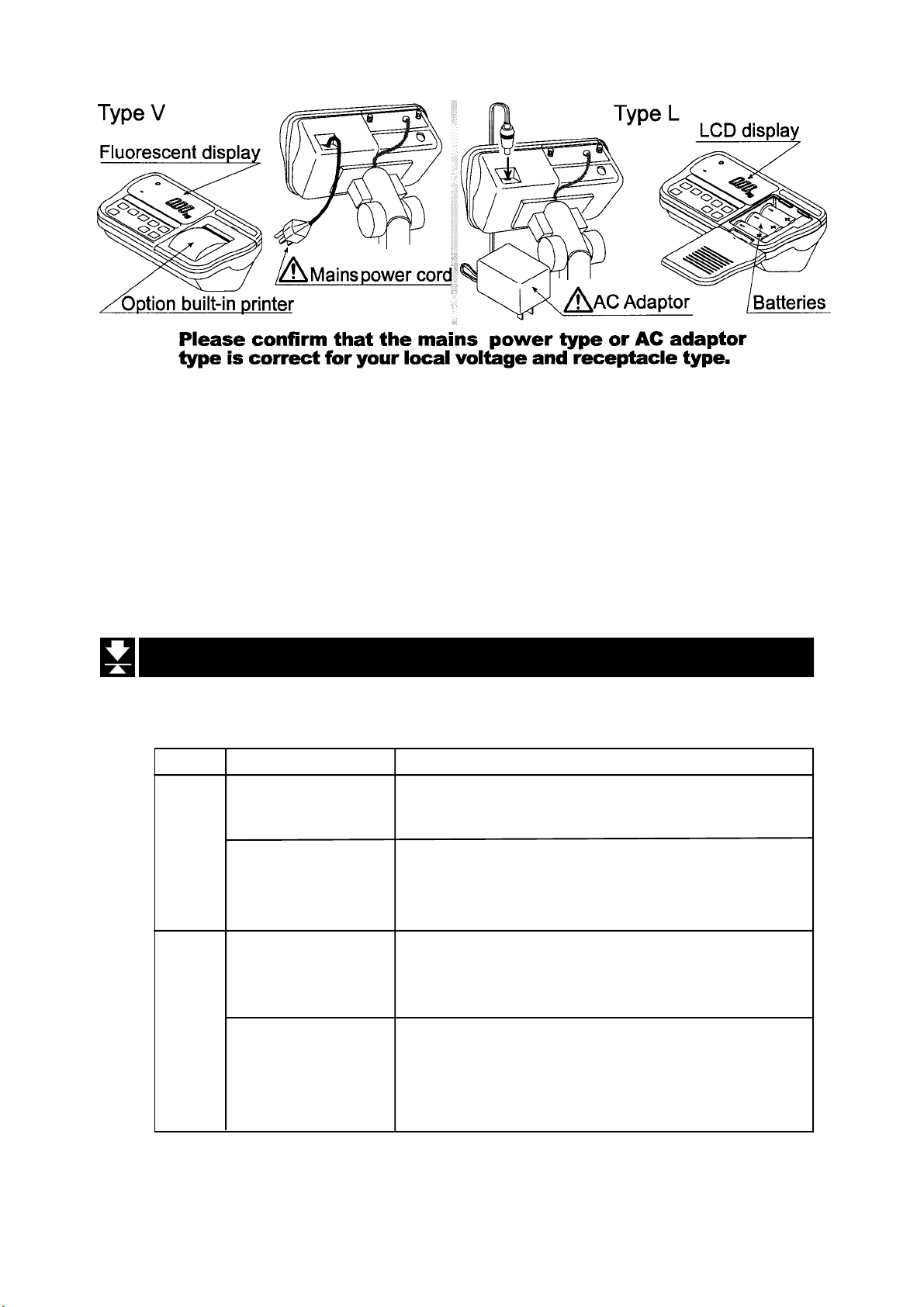
Type L scales have an LCD (Liquid Crystal Display) and use batteries as a power
source to provide portability. This type can also use an AC mains adaptor.
Type V scales have a fluorescent display so the weighing value can be read in
dim light. This type uses the AC power line as a power source.
The base unit (platform) is water-resistant in accordance with IP-65
specifications.
The counting mode function converts the total mass value (total weight) of articles
to a count, assuming all items to have the same mass.
The percentage mode function displays the mass of an item as a percentage of a
stored 100% mass.
The accumulation function accumulates each weighing value and counts the
number of weighings.
The comparator function compares the display value with the upper limit value
(HI) and the lower limit value (LO) and displays the result. The result can output if
option OP-03 is installed.
The simple batch function or full/dribble batch function can be used for filling to a
target mass value. The status of a weighing value can be output if option OP-03
or OP-04 is installed. The outputs are Zero Band, Preliminary and Final.
The optional RS-422/RS-485 serial interface can control up to 16 scales from a
computer when this option is installed in place of the standard RS-232C serial
interface.
Type V scales can be equipped with option OP-06, a built-in impact dot matrix
printer.
HW-G OZIM v1a
HW-G Instruction Manual Page 4
Page 7
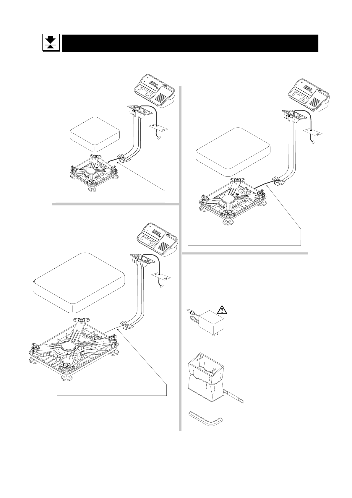
3 Unpacking
Display Unit
Products
HW-10KGL
HW-10KGV
Caution
Do not pull the load-cell cable.
Products
HW-100KGL
HW-200KGL
HW-100KGV
HW-200KGV
Display Uint
Products
HW-60KGL HW-60KGV
Pan
Base Unit
Caution
Do not pull the load-cell cable.
Base Unit
Pan
Caution
Do not pull the load-cell cable.
All Accessories
Refer to the accessries on page 6. The
combination of accessories depends upon
the model.
AC Adaptor
Please confirm that
the AC adaptor type
is correct for your
local voltage and
receptacle type.
Display unit cover
14:3003217
5mm allen wrench
HW-G Instruction Manual Page 5
HW-G OZIM v1a
Page 8
3.1 Accessories and Options list
Accessories for HW-G series
Type Products Accessories
HW-10KGV Display unit cover
Instruction manual
Type V HW-60KGV Display unit cover
HW-100KGV 5mm Allen wrench
HW-200KGV Instruction manual
HW-10KGL Display unit cover
AC adaptor
Instruction manual
Type L HW-60KGL Display unit cover
HW-100KGL 5mm Allen wrench
HW-200KGL AC adaptor
Instruction manual
HW-G OZIM v1a
HW-G Instruction Manual Page 6
Page 9
Options List
Order code or option name Accessories
OP-03 RS232C interface / Relay output / Buzzer Connector JA:TCP0586
OP-04 RS422/485 interface / Relay output Connector TM:BLA9
AC adaptor
OP-06 Built-in printer for type V Paper PP156
Ink ribbon ERC-05
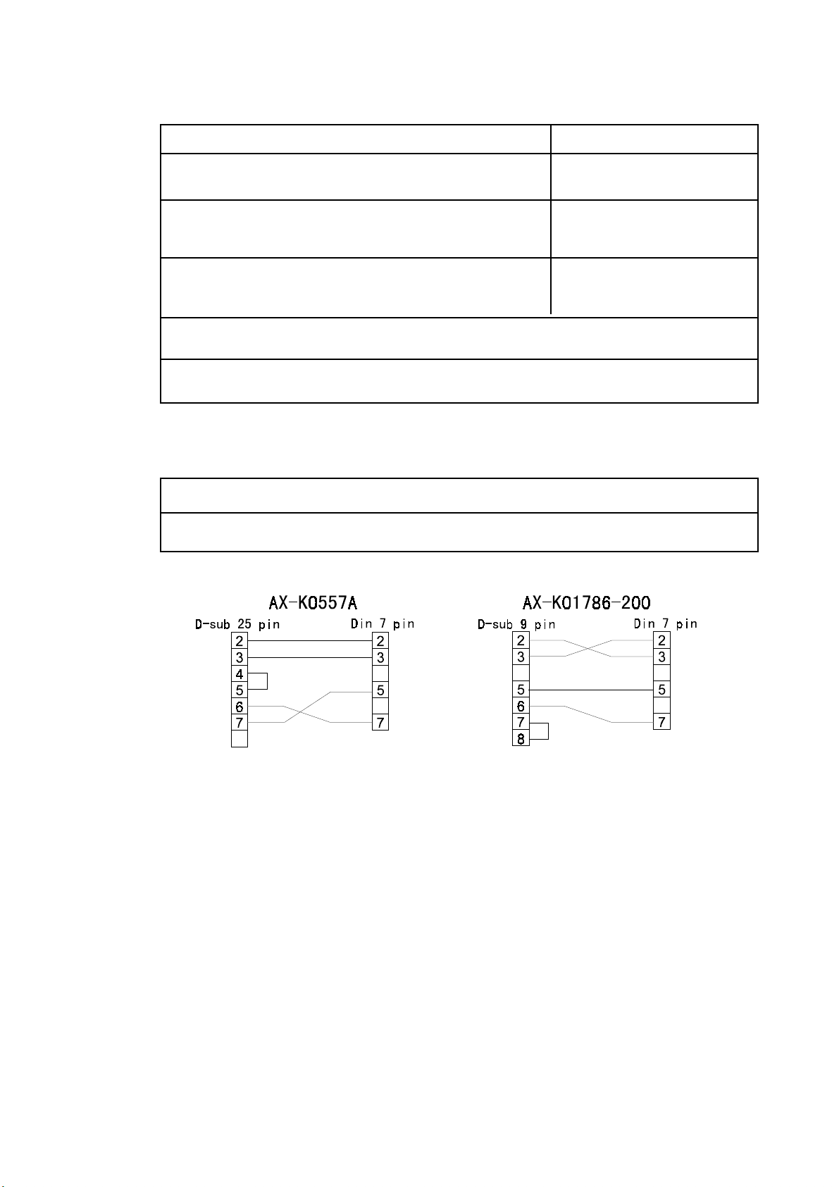
AX-K0557A RS232C cable, D-sub 25 pin, 2m
AX-KO1786-200 RS232C cable, D-sub 9 pin, 2m
Consumables
AX-PP156-S Special roll paper (10 rolls in a set)
AX-ERC-05-S Ink ribbon (5 ribbons in a set)
HW-G Instruction Manual Page 7
HW-G OZIM v1a
Page 10
4 Caution
4.1 Precautions for Installing the Scale
Consider the following conditions to get the most from your scale.
The best operation is where the temperature and relative humidity are stable, the
scale is installed on a solid floor or bench and there is no draft.
Do not install the scale in direct sunlight.
Do not install the scale near heaters or air conditioners.
Do not install the scale where there is flammable or corrosive gas present.
Do not install the scale near equipment which produces magnetic fields.
Do not install the scale where there is likely to be static electricity discharges in a
place where the relative humidity is lower than 45%RH. Plastic and isolators are
likely to be charged with static electricity.
The display unit is not water resistant. Use the display unit cover to avoid
damage.
Do not use an unstable power source.
4.2 Precautions for Operating the Scale
Periodically check the scale with a known weight.
Calibrate the scale before using it and after moving it to another location.
Do not place anything on the pan which is heavier than the weighing capacity
Do not drop anything onto the pan.
Do not use a sharp instrument such as a pencil or ball-point pen to press the
switches. Press the switches gently using only your finger.
We recommend pressing the ZERO or TARE switch before each weighing to
prevent possible error.
Replace used dry cells with six new ones when the BATT symbol is displayed.
Dry cell (battery) is size D.
4.3 Precautions for Storing the Scale
Do not disassemble the scale.
Do not use solvents to clean the scale.
For best cleaning of the display unit, wipe with a dry lint free cloth or a lint free
cloth which is moistened with warm water and a mild detergent.
The base unit can be cleaned with gentle water jets while brushing the base unit.
Weigh only after the unit is dry.
Protect the display unit from dust and water by using the vinyl cover.
Remove batteries from display unit when the scale is not in use for a long time. If
you leave the batteries installed they may leak and damage the scale.
HW-G OZIM v1a
HW-G Instruction Manual Page 8
Page 11
5 Installing the Scale
This procedure includes all of the steps for installing the HW-G series scales
Step 1 Unpacking
Remove the weighing pan from the carton and
place to one side. Remove the base unit and
column from the carton, taking care not to pull
on the loadcell cable.
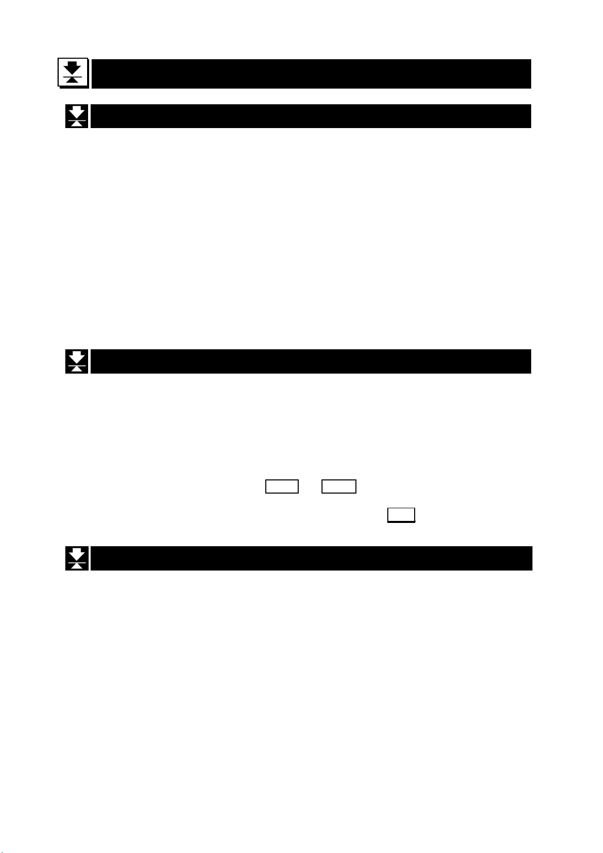
Step 2 Secure the Column
Step2 a Remove the 4 Allen screws from
the column lower bracket.
Step 2b Pull the excess loadcell cable
through the column as you position the column to the base unit, so as not to damage
the loadcell cable. Affix the column to the
base unit using four 5mm Allen screws.
Stpe 3 Secure the Display Unit
Step3 a Remove the 2 screws from the rear
of the display unit, position the display unit
onto the column bracket and pull the excess
cable back down the centre of the column to
the base unit. Ensure that the cable exits via
the cut out in the display unit column bracket
and secure the headwork with the 2 screws.
Step 2a
Base unit
Step 2b
5mm allen screws
Column
Step 1
Load-cell cable
Allen wrench
Step 3b Carefully make the connection
between the cable connector and J1 inside
the headwork, then secure the rear display
panel.
Step 4 Fit the Pan
Step 4 Fold the excess cable at the
basework end and secure with the ‘twist and
tie’ strip provided.
Fit the pan to the base unit.
Tie excess cable here
Step 3
Screws
Step 4
HW-G Instruction Manual Page 9
HW-G OZIM v1a
Page 12

Select the place where you intend to instal the scale.
Step 6
Consider “4. Caution” on page 8.
Step 5 Level the Scale
Level the base unit by using the “Bubble spirit level”
and “Levelling feet”.
Step 6 Adjust the Display Unit
Press the caps at the pole top from both sides and
adjust the angle of the display unit.
Bubble spirit level
Leveling foot
Step 5
OK NG
Step7 Connect the Power
Install the batteries (see page 11) or connect the AC
adaptor or mains cable. Check the weighing accuracy.
If the scale needs calibration, refer to “14 Calibration”.
HW-G OZIM v1a
HW-G Instruction Manual Page 10
Page 13
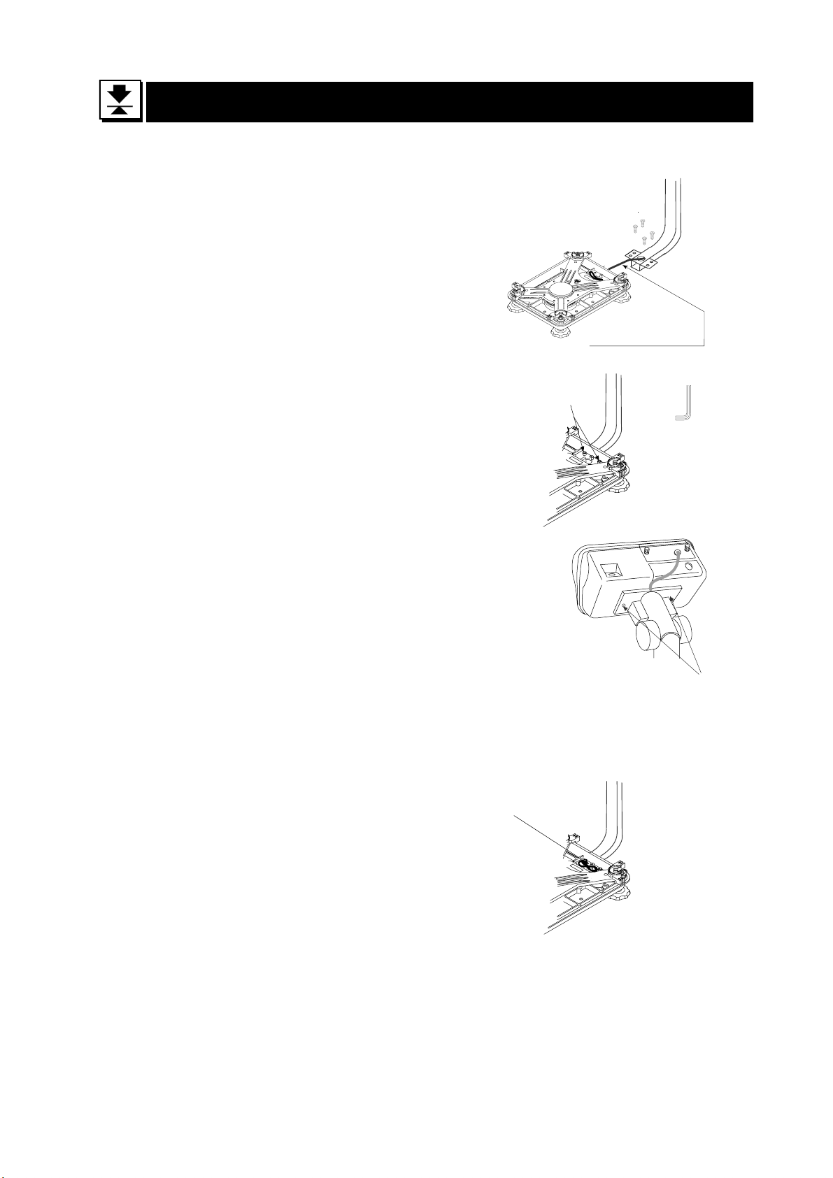
5.1 Installing the Batteries for Type L
Step 1 If necessary turn off the display
and remove the AC adaptor.
Step 2 Press and slide downwards to remove the
external cover.
Press the hook of the internal cover to the
left side and lift off the cover.
Step 3 Insert six new dry cells ensuring correct
polarity (+,-). Battery size is ‘D’.
Step 4 Replace the covers removed in step 2.
Caution
Replace used dry cells with six new ones, when
Do not mix used and new batteries. It may cause damage to the battery
or product.
Check the polarity when installing the batteries. If you do not observe
this it may cause battery leakage. Also if the polarity of a battery is
wrong the scale may only work temporarily.
The battery life is dependent upon the environmental temperature.
Remove batteries from the display unit when the scale is not to be used
for a long time. They may leak and cause damage.
Damage which is due to battery leakage is not covered under warranty.
BATT is displayed.
HW-G Instruction Manual Page 11
HW-G OZIM v1a
Page 14
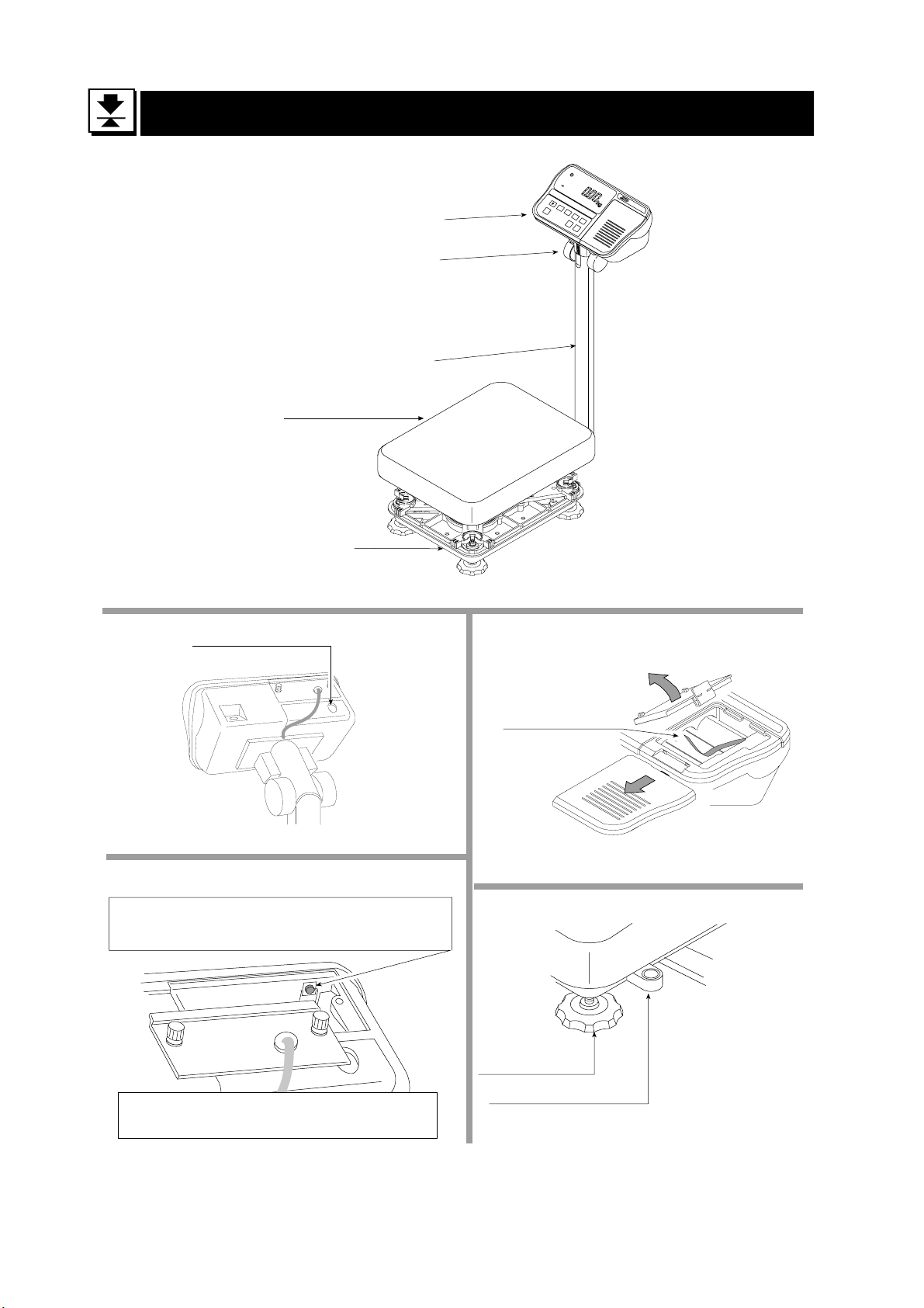
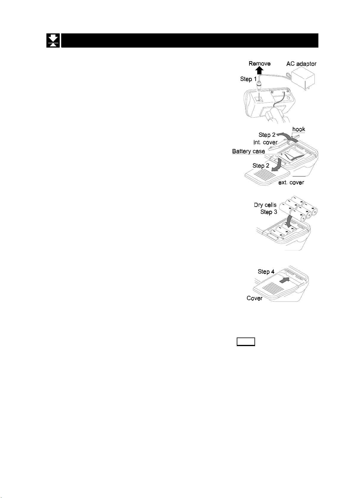
6 Names
Angle adjustment
Weigh pan
Base unit
Display unit
Column
RS-232C Interface connector
CAL switch
Calibrating the scale to weigh it correctly.
Type L
Battery Case
Leveling Foot
Caution
It is necessary to use classified mass.
HW-G OZIM v1a
HW-G Instruction Manual Page 12
Bubble Spirit Level
Page 15
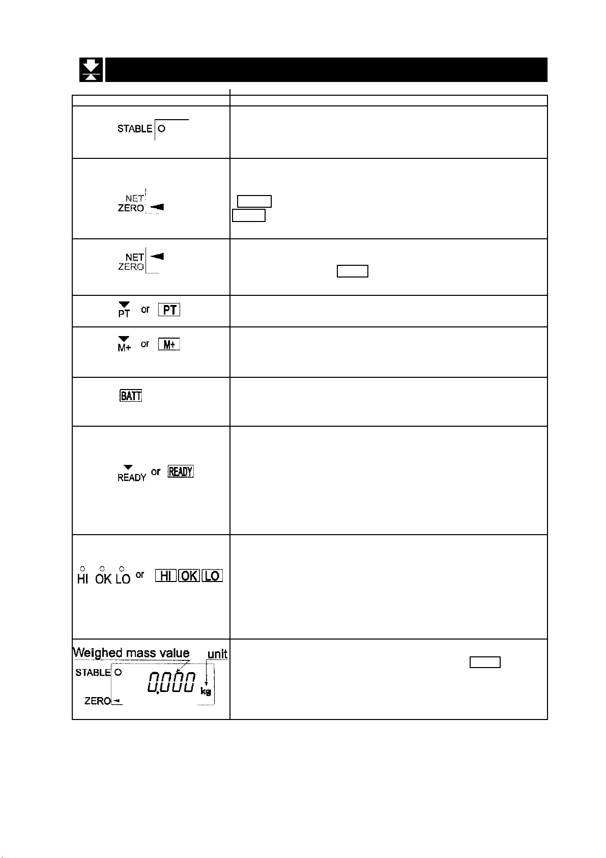
6.1 Display and Symbols
Display and Symbols Meaning
Stability mark.
When the current weight value is not changing, this mark
is displayed. The reading may now be taken.
Zero point mark.
With nothing on the pan and pressing the
ZERO switch or with a mass on the pan and pressing the
TARE switch, this mark is displayed. The zero point is the
starting point to weighing.
Net mark.
After pressing the TARE switch this mark is displayed to
show net weight is displayed
Preset tare mark.
When storing a tare with digital input this mark blinks.
Accumulation mark.
When using the accumulation function, this mark is
displayed.
Low battery mark for type L.
When the battery power is low this mark is displayed.
Replace with six new batteries.
Ready mark for the full/dribble batch function. This mark
shows:
ON The weighing value is within the zero-band.
OFF The full/dribble batch process is above the
zero-band.
Blinking The start or end of the full/dribble batch
process above the zero-band.
The comparator indicator.
Using the comparator function and comparing a weighing
value with the upper and lower limits, the result is
indicated.
Using the full/dribble batch function, the full flow gate
indicator is shown as OK, the dribble flow gate indicator as
HI and the zero band indicator as LO.
Example:- Display of zero (zero point).
With an empty weighing pan by pressing the ZERO switch:The Zero mark is displayed.
The stability mark is displayed.
HW-G Instruction Manual Page 13
HW-G OZIM v1a
Page 16
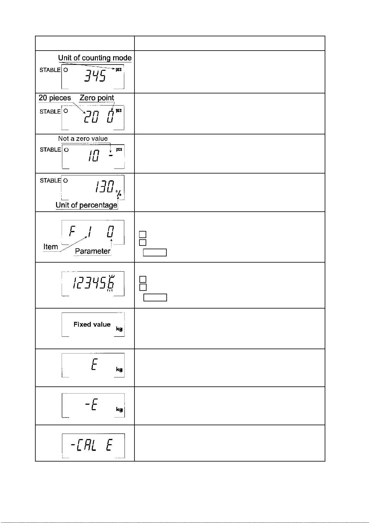
Display and Symbols Meaning
Example:- Display of the counting mode.
This mode uses the registered unit mass, counts the
quantity of articles on the pan. The unit is
Example:- Storing the unit mass in the counting mode.
This is a display of zero point for counting mode and uses
20 pieces for the unit mass registration.
Example:- Storing the unit mass in the counting mode.
Sign “-” means “weighing value is not zero”.
Sample number is 10 pieces.
Example:- Percentage mode.
This mode uses the registered 100% mass, converts the
weighing value to a percentage. The unit is % .
Example:- Display of the function table.
This function table sets parameters of items.
< switch Selecting an item.
^ switch Selecting a parameter of the item.
ENTER switch Storing new parameters.
PCS
.
Example:-. Preset tare. Entering tare with digital input.
< switch Selecting a figure.
^ switch Selecting a number.
ENTER switch Storing new tare.
Example:- Hold display
The hold display is set using f12 of the function table.
When weighing value is “near-zero” or changes more than
25% +30 digits, the hold is cancelled.
Overload display.
Remove everything from the pan.
Weighing error.
Check the base unit and weighing pan.
Calibration error.
Means “Calibration mass is too light”.
Check the base unit and weighing pan.
HW-G OZIM v1a
HW-G Instruction Manual Page 14
Page 17
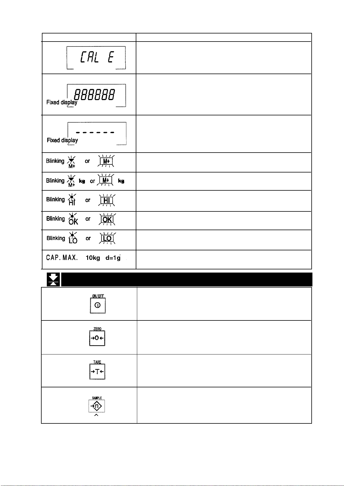
Displays and Symbols Meaning
Calibration error.
Means “Calibration mass is too heavy”.
Check the base unit and weighing pan.
Weighed value is unstable due to drift, vibration etc. when
turning on the scale.
Check around the weighing pan.
Check the connection of the load cell cable.
Remove everything from the weighing pan.
Check around weighing pan.
Perform zero point calibration of the scale.
Accumulated data count
Total mass value of the accumulated data.
Comparator function = display is an upper limit.
Full/dribble batch function = display is a final value.
6.2 Switches
Full/dribble batch function = display is a preliminary value.
Comparator function = display is a lower limit.
Full/dribble batch function = display is the zero band.
Description of the weighing capacity and minimum
graduation.
Power switch.
Note Type V is in standby status when power is
connected.
Zero switch.
When there is nothing on the pan and the ZERO switch
is pressed, the scale displays zero and the zero point mark.
Any stored tare is cancelled.
Tare switch.
Used to store the weight of a container when carrying out
net weighing.
Sample switch.
Storing the unit mass it is used to select a sample number.
In the function table it is used to select a parameter.
HW-G Instruction Manual Page 15
HW-G OZIM v1a
Page 18
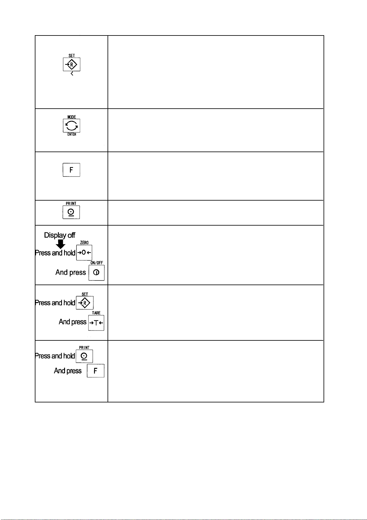
Set switch.
Can be used to turn the comparator on/off. (Refer to f6 )
Counting mode, it is used to enter the mode to store the unit mass.
Percentage mode, it is used to enter the mode to store the 100%
mass.
In the full/dribble batch function, it is used as a start switch.
In the preset tare, and selecting calibration mass, it is used to
select a figure.
Mode switch.
Used to change the current unit.
While setting modes, this switch is used for “storing a parameter
and proceeding the next step”.
F switch
Full/dribble batch function it is used to finish the process.
(Refer to f10 )
Hold switch. (Refer to f12 )
Setting a preset tare, selects polarity (+,-).
Print switch.
Used to print or output data. (Refer to f5, f9 )
Used to enter the function table
Used to enter the mode to set a preset tare
Used to perform paper feed for the optional printer for type V.
HW-G OZIM v1a
HW-G Instruction Manual Page 16
Page 19
7 Basic Operation
7.1 Turning the Scale On/Off & Basic Weighing
7.1.1 Type V or Type L with AC adaptor
Step 1 Ensure that the pan is empty.
Step 2 Confirm that local voltage and receptacle type match your scale.
Step 3 The scale turns on/off using the ON/OFF switch alternately.
Step 4 Check the accuracy of weighing. If you calibrate the scale, perform it after
allowing the scale to warm up for 30 minutes.
Step 5 Press the ZERO switch to display zero. (With nothing on the pan.)
Step 6 Place something gently onto the pan.
Step 7 You can read the weight after the stability mark is displayed.
Step 8 Remove the item from the pan.
Step 9 Turn the scale off using the ON/OFF switch.
Memo
With the power cord connected, type V consumes only sufficient power for standby
status after turning off the scale.
With the AC adaptor connected, type L consumes only the power of the AC adaptor
after turning off the scale.
HW-G Instruction Manual Page 17
HW-G OZIM v1a
Page 20
7.1.2 Type L with Batteries
Step 1 Install six new batteries. Refer to “5.1. Installing the batteries for Type L”.
Step 2 Ensure that the pan is empty.
Step 3 The scale turns on/off using the ON/OFF switch alternately.
Step 4 Check the accuracy of weighing. If you calibrate the scale, perform it after
warming up the scale for 30 minutes. You will need to disable the auto power
off function. See 15.2 page 43.
Step 5 Press the ZERO switch to display zero. (With nothing on the pan.)
Step 6 Gently place something on the pan.
Step 7 You can read the weight value after the stability mark is displayed.
Step 8 Remove the item from the pan.
Step 9 Turn the scale off using the ON/OFF switch.
Caution
Replace used dry cells with six new ones when BATT is displayed.
Battery life is affected by the environmental temperature.
Remove batteries from the display unit when the scale is not to be used for a long
time. The batteries may leak and cause damage.
HW-G OZIM v1a
HW-G Instruction Manual Page 18
Page 21
7.2 Tare (and Net Display)
The “Tare” is used to cancel the mass of a container, receptacle, case, bag, etc.
which is put on the pan to contain the item to be weighed.
Caution
The tare reduces the available weighing range.
The current tare value is reset by pressing the ZERO switch when the pan is
empty, or by turning the scale off. (Reset value is zero.)
7.2.1 Semi-Automatic Tare (Input by Weighing)
Step 1 Put the container onto the pan.
Step 2 Press the TARE switch. The display becomes zero and the net mark
is displayed.
Step 3 It is now possible to put something into the container and to read its
net display.
Step 4 Remove all items from the pan.
7.2.2 Preset Tare (Digital Input of Known Tare)
Step 1 Press and hold the SET switch and press the TARE switch.
Then the blank or stored tare value is displayed. This blank display
means that the tare value is zero (reset value) and blinks.
Step 2 Set the preset tare value by using the following switches.
^ switch selecting the value of a digit.
< switch selecting a digit.
Step 3 Press the ENTER switch to store the new preset tare value.
The scale displays a net value i.e. the tare value subtracted from the
gross weight value.
Step 4 It is now possible to put something onto the pan and to read its net
weight.
Step 5 Remove all items from the pan.
HW-G Instruction Manual Page 19
HW-G OZIM v1a
Page 22
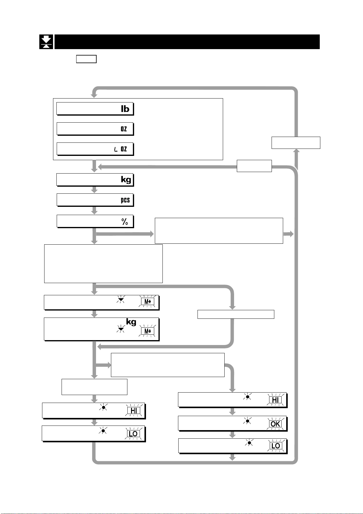
7.3 Mode Switch (Changing Unit & Mode)
Pressing the MODE switch the display changes as shown below. Refer to the function
table f3 for available units. Useable units are according to the factory settings.
Pound
Ounce
Pound-Ounce
Metric kg
Counting Mode
Percentage Made
Either function is active.
Comparator (f6 1 ~ f6 7)
Simple Batch Function (f6 8)
Full/Dribble Batch Function (f6 9)
Accumulation Function (f8 1)
If the law in your area
premits, you may use all
of the units. Also, some
dealers may initially turn
off units which are not
regularly used.
Non metric units
Metric unit
Inactive Comparator (f6 0)
and
Inactive Accumulation Function (f8 0)
Accumulation Count
Accumulation Value
Active Comparator
(f6 1 ~ f6 7)
Comparator
Upper limit
Comparator
Lower limit
HW-G OZIM v1a
or
M+
or
M+
Active Simple Batch Function or
Active Full/Dribble Batch Function
(f6 8, f6 9)
Final value
or
HI
Preliminary value
or
LO
Zero band
HW-G Instruction Manual Page 20
No Accumulation Data
or
HI
or
OK
or
LO
Page 23

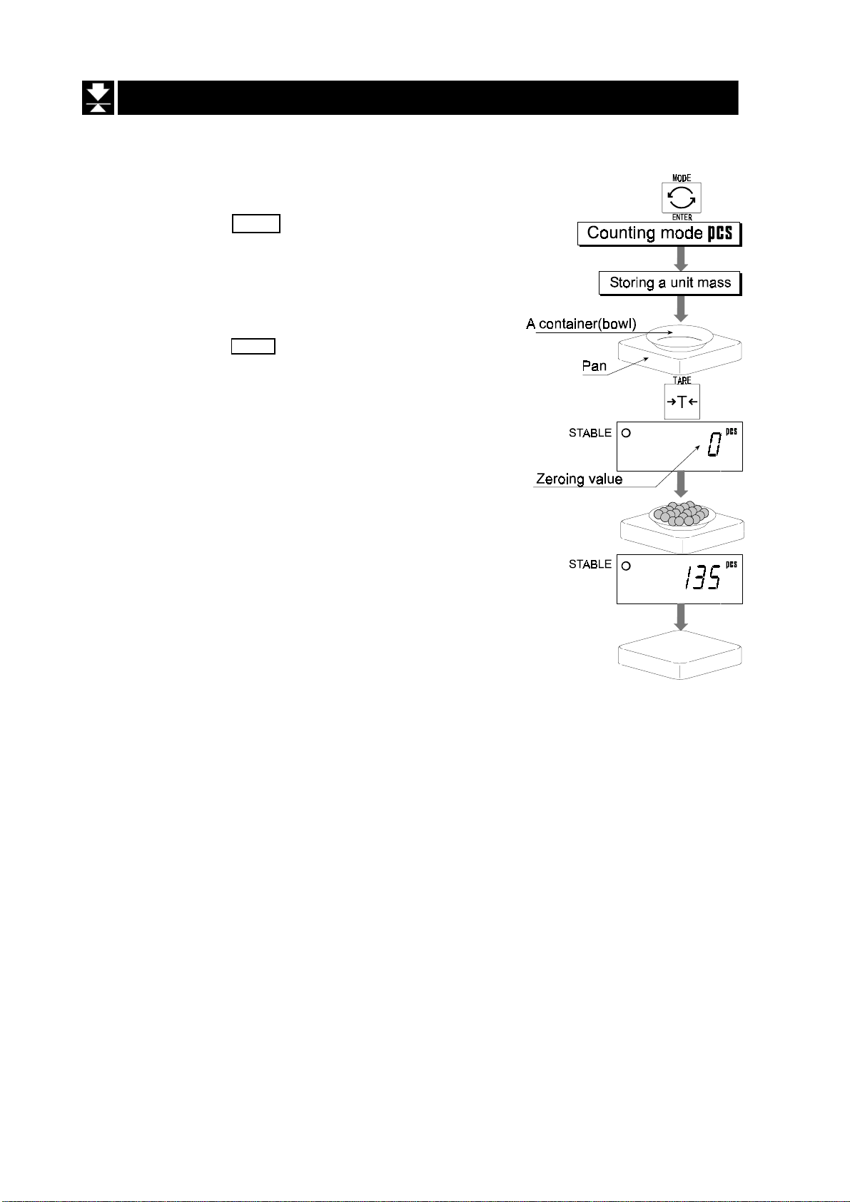
Counting Mode
8 Counting Mode
In counting mode the total weight of articles is converted to a count and assumes
all articles have the same mass value.
It is necessary to store a unit mass to count articles.
8.1 Storing a Unit Mass
Step 1 Press the MODE switch to display the unit
Step 2 Press the SET switch to enter the mode to store
a unit mass.
Step 3 Press the ^ switch to select the number of
samples. The greater the quantity of samples, the
greater the accuracy of the count. Select from
5 pieces, 10 pieces, 20 pieces, 50 pieces, 100
pieces
Step 4 Put the container onto the pan.
Press the TARE switch.
Step 5 Put in the number of samples selected at step 3.
Press the ENTER switch to store the weight after
the stability mark is displayed. The count is then
displayed.
Caution
When the sample is too light and it is not possible to
calculate a unit mass, the scale displays lo ut and
returns to step 3. It is necessary to increase the
number of samples.
Pressing the ENTER switch after the lo ut . is
displayed, the next unit is displayed.
When the unit mass is too light to store, the scale
displays lo ut .
PCS
.
Step 4 Remove all items from the pan.
HW-G Instruction Manual Page 21
HW-G OZIM v1a
Page 24
8.2 Counting the number of articles
Step 1 Press the MODE switch to display the unit
Step 2 Store the unit mass of the item.
Refer to “8.1 Storing a Unit Mass”
Step 3 Put the container only onto the pan.
Press the TARE switch.
Step 5 Put articles into the container and read the
count.
Step 6 Remove all items from the pan.
PCS
HW-G OZIM v1a
HW-G Instruction Manual Page 22
Page 25
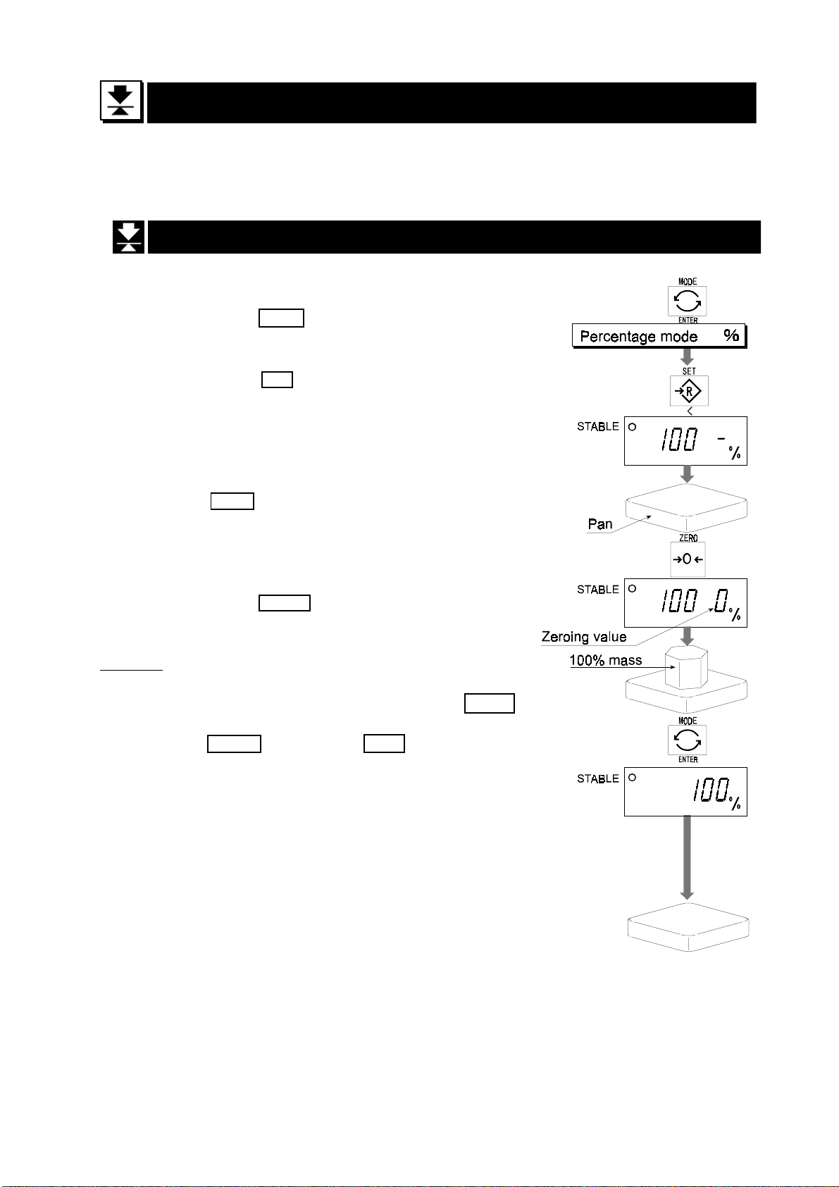
9 Percentage Mode
The percentage mode is to display a mass value in the unit of “%”.
It is necessary to store a 100% mass value in advance to use this function.
9.1 Storing a 100% Mass
Step 1 Press the MODE switch to display the unit %.
Step 2 Press the SET switch to enter the mode that
stores a 100% mass.
Step 3 If necessary, with nothing on the pan press
the ZERO switch to display zero.
Step 4 Gently place the 100% mass onto the pan.
Press the ENTER switch to store the mass
after the stability mark is displayed. Then the
percentage unit is displayed.
Caution
When the sample is too light and it is not possible
to calculate a 100% mass, the scale displays lo .
and returns to step 3.
Pressing the ENTER switch after lo is displayed,
the next unit is displayed.
Step 5 Remove all items from the pan.
HW-G Instruction Manual Page 23
HW-G OZIM v1a
Page 26

9.2 Reading Percentage
Step 1 Press the MODE switch to display the
unit %.
Step 2 Store the unit mass of the article.
Refer to “9.1 Storing a 100% Mass “
Step 3 If a container is needed, put the
container only onto the pan and press
the TARE switch.
Step 4 It is now possible to put the item into the
container and read the percentage.
Step 5 Remove all items from the pan.
HW-G OZIM v1a
HW-G Instruction Manual Page 24
Page 27

10 Accumulation Function
This function counts the number of weighed items, calculates the total mass value and
can display the number and accumulated mass value.
It is necessary to set the parameters of the “accumulation function ( f8 )” in the function
table in advance to use this function.
It is necessary to set the parameters of the “print mode ( f9 )” in the function table in
advance to use the optional built-in printer.
Operation and Switches
The display of the accumulation count has a blinking M+ or without a unit.
The display of the accumulation value has a blinking M+ kg or kg with a unit.
Pressing the MODE switch, the accumulation count and accumulation value is displayed.
Pressing the ZERO switch in the accumulation function while a blinking M+ or is
displayed, resets the current function. The count and accumulated value become zero.
When the optional built-in printer is installed and the PRINT switch is pressed, the
accumulation data, date and data number are printed. Date is set at function table f16 .
Caution
The accumulation function can only be used with the first weighing unit
accumulated, e.g. you cannot accumulate pcs while displaying kg.
Parameter List and Word Definition
The “near-zero” is within ±4 digits from the zero point in the unit of kg.
The “digit”, a unit of display, is equivalent to the minimum graduation.
The “zero point” is the fundamental starting point to weighing.
Function table Meaning & Purpose
f8 0 Accumulation function not used.
The scale accumulates the data, if the F switch is pressed when
the display is a positive stable value above near-zero. The next
f8 1 accumulation can be performed after the display returns to
near-zero or to a negative value.
f8 2 The scale accumulates the data, if the F switch is pressed, when
the display is a stable value and outside near-zero. The next
accumulation can be performed after the display returns to
near-zero.
f8 3 When the display is a positive stable value, the scale accumulates
the data automatically. The next accumulation can be performed
after the display returns to near-zero or to a negative value.
HW-G Instruction Manual Page 25
HW-G OZIM v1a
Page 28
Function table Meaning & Purpose
f8 4 When the display is a stable value, the scale accumulates the data
automatically. The next accumulation can be performed after the
display returns to near-zero.
Use Recording the number and mass of articles removed from the
pan. (Put the articles on the pan. Press the TARE switch at each
removal.)
f8 5 At each finish of the full/dribble batch function, the scale accumulates
the data automatically.
Use Packaging articles like a powder, it is used for recording the
bag number and total mass.
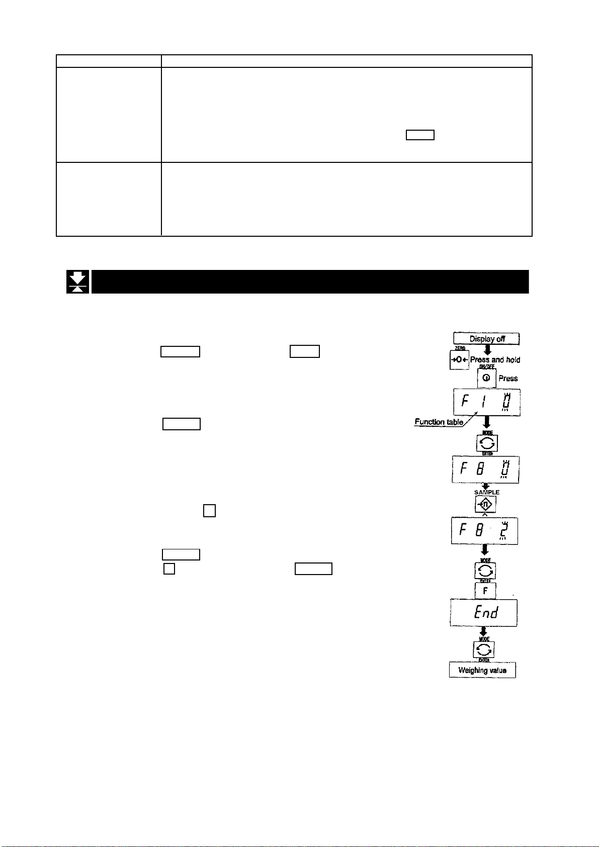
10.1 Preparation (Setting Parameters)
Step 1 Turn off the display.
Press the ON/OFF switch while the ZERO switch is
pressed and held. The function table is displayed.
Step 2 Press the ENTER switch to display an item of the
accumulation function ( f8 ).
Step 3 Select a parameter of the accumulation function ( f8 1
~ f8 4 ) with the ^ switch.
Step 4 Press the ENTER switch to store the new parameter.
Press the F switch and then the ENTER switch to exit
from the function table. Then the scale displays the
weighing mode.
HW-G OZIM v1a
HW-G Instruction Manual Page 26
Page 29

10.2 Operation and Performance (Examples)
Example 1
Weighing each article, the scale makes the accumulation according to f8 3 .
Step 1 Press the MODE switch to display M+ or .
Step 2 Press the ZERO switch to reset the accumulation data.
Step 3 Return to the kg mode using the MODE switch.
Press the ZERO switch with nothing on the pan.
Step 4 Put an article on the pan. Wait for the stability mark to be displayed and the
value to blink. Remove the article and, if necessary, press the ZERO switch.
Step 5 Weigh additional articles using step 4.
Step 6 Press the MODE switch to display the number of articles and total mass with
M+ or displayed.
Example 2
This example accumulates the articles that were removed from the pan. The
function parameter is set to f8 4 .
Step 1 Enter into the kg mode using the MODE switch.
Put all articles on the pan and press the TARE switch.
Step 2 Press the MODE switch to display M+ or .
Step 3 Press the ZERO switch to reset the accumulation data.
Retun to kg mode with the MODE switch.
Step 4 Remove an article from the pan. Wait for the stability mark to be displayed and
the value to be blinking. Press the TARE switch.
Step 5 Remove additional articles using step 4.
Step 6 Press the MODE switch to display the number of articles and total mass
removed, with M+ or displayed.
HW-G Instruction Manual Page 27
HW-G OZIM v1a
Page 30

11 Comparator Function
This function compares a display value with the upper limit (HI) and the lower limit (LO)
and displays these results.
It is necessary to set the “comparator function ( f6 0 ~ f6 7 )” parameters, upper limit
value (HI) and lower limit value (LO) in the function table, in advance to use this function.
It is necessary to install option OP-03 or OP-04, if you use the relay output of the
comparator.
Comparator Sign
Comparison results are displayed by indicators
Comparison Condition
weighing value < lower limit value LO is displayed and output.
lower limit value < weighing value < upper limit value OK is displayed and output.
upper limit value < weighing value HI is displayed and output.
Parameter List and Word Definition
The “ near-zero “ is within ±4 digits from the zero point in the unit of kg.
The “digit” is a unit of display, and is equivalent to the minimum graduation.
The “zero point” is the fundamental starting point to weighing.
Function table Meaning and Purpose
f6 0 Having pressed the SET switch, the scale will always compare the
current display value.
f6 1 The scale always compares the display value.
f6 2 Pressing the SET switch the scale always compares the display value
if not near-zero.
f6 3 The scale always compares the display value if not near-zero.
f6 4 When the display value becomes stable after pressing the SET
switch, the scale compares the display value. If the SET switch is
pressed again the scale stops the comparison.
f6 5 When the display value is stable the scale compares the display
value. It does not compare on an unstable condition.
f6 6 When the display value becomes stable while not near-zero, after
pressing the SET switch, the scale compares the display value. It
does not compare on an unstable condition. If the SET switch is
pressed again the scale stops the comparison.
f6 7 When the display value becomes stable and not near-zero, the scale
compares the value.
Caution
The upper limit value (HI) must be equal to or greater than the lower limit value (LO).
The parameters of the upper limit value (HI) and the final value (HI) use the same memory.
The parameters of the lower limit value (LO) and the zero band (LO) use the same memory.
The upper/lower comparator function, the simple batch function and the full/dribble batch
function cannot be used at the same time because these parameters use common memory.
HW-G OZIM v1a
HW-G Instruction Manual Page 28
Page 31

11.1 Preparation (Setting Parameters)
Step 1 Turn off the display.
Press the ON/OFF switch while the ZERO switch is
pressed and held. The function table is displayed.
Step 2 Press the ENTER switch to display an item of the
accumulation function ( f6 ).
Step 3 Select a parameter of the comparator function
( f6 0 ~ f6 7 ) with the ^ switch.
Step 4 Press the ENTER switch to store the new parameter.
Step 5 Press the F switch and the ENTER switch to exit from
the function table. Then the scale displays the
weighing mode.
HW-G Instruction Manual Page 29
HW-G OZIM v1a
Page 32

Step 6 If one of f6 0 , f6 2 , f6 4 , f6 6 has
been selected, press the SET switch to
use the comparator.
Step 7 Press the MODE switch to display the
HI, blinking.
Step 8 Set the upper limit value by using the
following switches.
^ switch Selecting the value of a digit.
< switch Selecting a digit.
F switch Selecting the polarity (+,-).
Step 9 Press the ENTER switch to store the new
parameter and display the blinking LO.
Step10 Set the lower limit value by using the
following switches.
^ switch Selecting the value of a digit.
< switch Selecting a digit.
F switch Selecting the polarity (+,-).
Step 11 Press the ENTER switch to store the
new parameters and display the
weighing mode.
HW-G OZIM v1a
HW-G Instruction Manual Page 30
Page 33

11.2 Operation and Performance (Examples)
Example 1
This example is set as follows:
Function table
Upper limit value (HI) 7.000kg
Lower limit value (LO) 6.500kg
Case
The comparison starts at turning the scale on.
When the current value is less than 6.500kg, LO is displayed.
When the current value is between 6.500kg and 7.000kg, OK is displayed.
When the current value is greater than 7.000kg, HI is displayed.
Example 2
This example is set as follows:
Function table f6 4 (Pressing the SET switch, after the stability
Upper limit value (HI) 2.000kg
Lower limit value (LO) -1.000kg
f6 3 (If the current display value is not near-zero,
the scale compares the display value with the
upper limit value and the lower limit value
immediately.)
mark is displayed, the scale compares the
current display value with the upper limit value
and the lower limit value immediately.)
Case
Pressing the SET switch, after displaying the stability mark ,the comparison is
performed.
When the current value is less than -1.000kg, LO is displayed.
When the current value is between -1.000kg and 2.000kg, OK is displayed.
When the current value is greater than 2.000kg, HI is displayed.
HW-G Instruction Manual Page 31
HW-G OZIM v1a
Page 34
12 Full/Dribble Batch Function
This function changes the scale to a filling machine which sub-divides a bulk product like
grain into loads of predetermined and virtually constant mass.
It is necessary to set the parameter of the “comparator function ( f6 9 )”, “ full/dribble
batch sub-function ( f10 0 ~ f10 3 )” in the function table, final value (HI), preliminary
value (OK) and zero band (LO) in advance to use this function.
It is necessary to install option OP-03 or OP-04, if you use the relay output of the full/
dribble batch function.
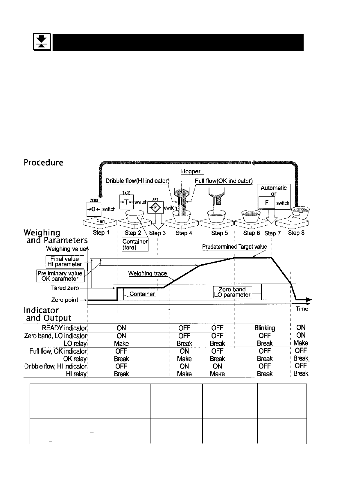
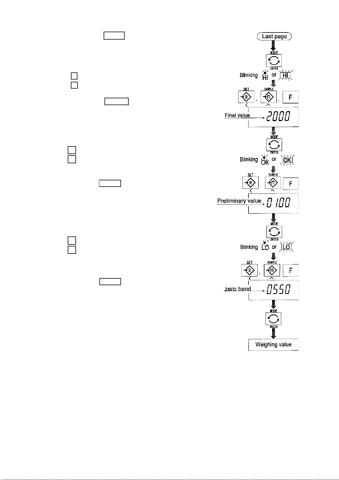
In the example of a filling machine with a scale and hopper, the performance and
processing of the system are assumed to be as follows:
Zero Band Preliminary value Final value
indicator/ indicator/ indicator/
LO relay output OK relay output HI relay output
Gross < Zero band (Zero detection level) ON/Make OFF/Break OFF/Break
Net < Final - Preliminary OFF/Break ON/Make ON/Make
Final - Preliminary < Net < Final OFF/Break OFF/Break ON/Make
Final < Net OFF/Break OFF/Break OFF/Break
HW-G OZIM v1a
HW-G Instruction Manual Page 32
Page 35
Caution
The comparison of the full/dribble batch function is not reversible (One way sequence). If the display value becomes less than the final value after the value reached
a predetermined target value, neither HI or LO is on.
The parameters of the upper limit value (HI) and the final value (HI) use the same
memory. The parameters of the lower limit value (LO) and the zero band (LO) use
the same memory.
The upper/lower comparator function, the simple batch function and the full/dribble
batch function cannot be used at the same time because these parameters use
common memory.
Set the zero band greater than the tare value.
Operation
Pressing the SET switch, the scale starts the batch process.
Selecting a parameter from f10 0 or f10 2 of the full/dribble batch sub-function,
the F switch works as the finish switch.
Parameter List and Word Definition
The “gross” is a total weighing value, no tare value is subtracted.
The “net” is a measurement value with the tare value subtracted from the gross.
The “zero band” means the zero detection level.
The “zero point” is the fundamental starting point to weighing.
Comparator
Function table Meaning and purpose
f6 9 Full/Dribble batch function
Full/Dribble batch sub-function
Function table Meaning and purpose
f10 0 Reaching final value and pressing the F switch the current process is
finished.
f10 1 Reaching the final value and displaying the stability mark the current
process is finished automatically.
f10 2 Pressing the SET switch the scale automatically tares and starts the
full/dribble batch process. Reaching final value anf pressing the F switch,
the current process is finished.
f10 3 Pressing the SET switch the scale automtically tares and starts the
full/dribble batch process. Reaching the final value and displaying the
stability mark the current process is finished.
Hold
Function table Meaning and purpose
f12 0 The hold function is not used
HW-G Instruction Manual Page 33
HW-G OZIM v1a
Page 36
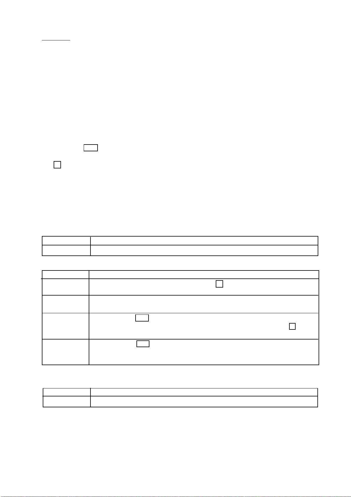
12.1 Preparation (Setting Parameters)
Step 1 Turn off the display.
Press the ON/OFF switch while the ZERO switch
is pressed and held. The function table is displayed.
Step 2 Press the ENTER switch to display an item of
the comparator function ( f6 ).
Step 3 Select a parameter of the full/dribble batch
function ( f6 9 ) with the ^ switch.
Step 4 Press the ENTER switch to store the new
parameter and display an item of the full/dribble
batch sub-function ( f10 ) .
Step 5 Select a parameter of the full/dribble batch sub-
function ( f10 0 ~ f10 3 ) with the ^ switch.
Step 6 Press the ENTER switch to store the new
parameter
Step 7 Press the F switch and the ENTER switch to
exit from the function table. Then the scale displays the weighing mode.
HW-G OZIM v1a
HW-G Instruction Manual Page 34
Page 37
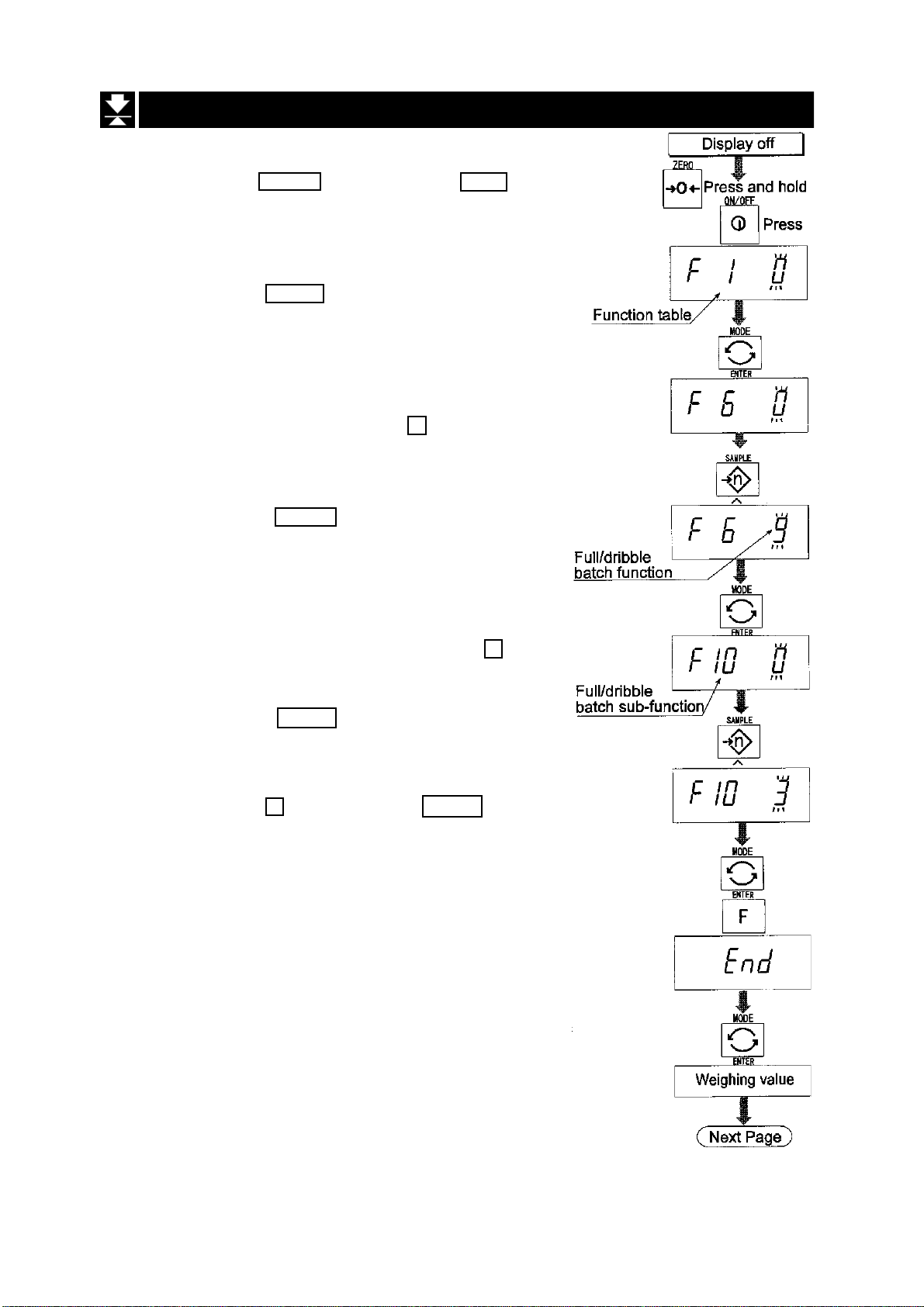
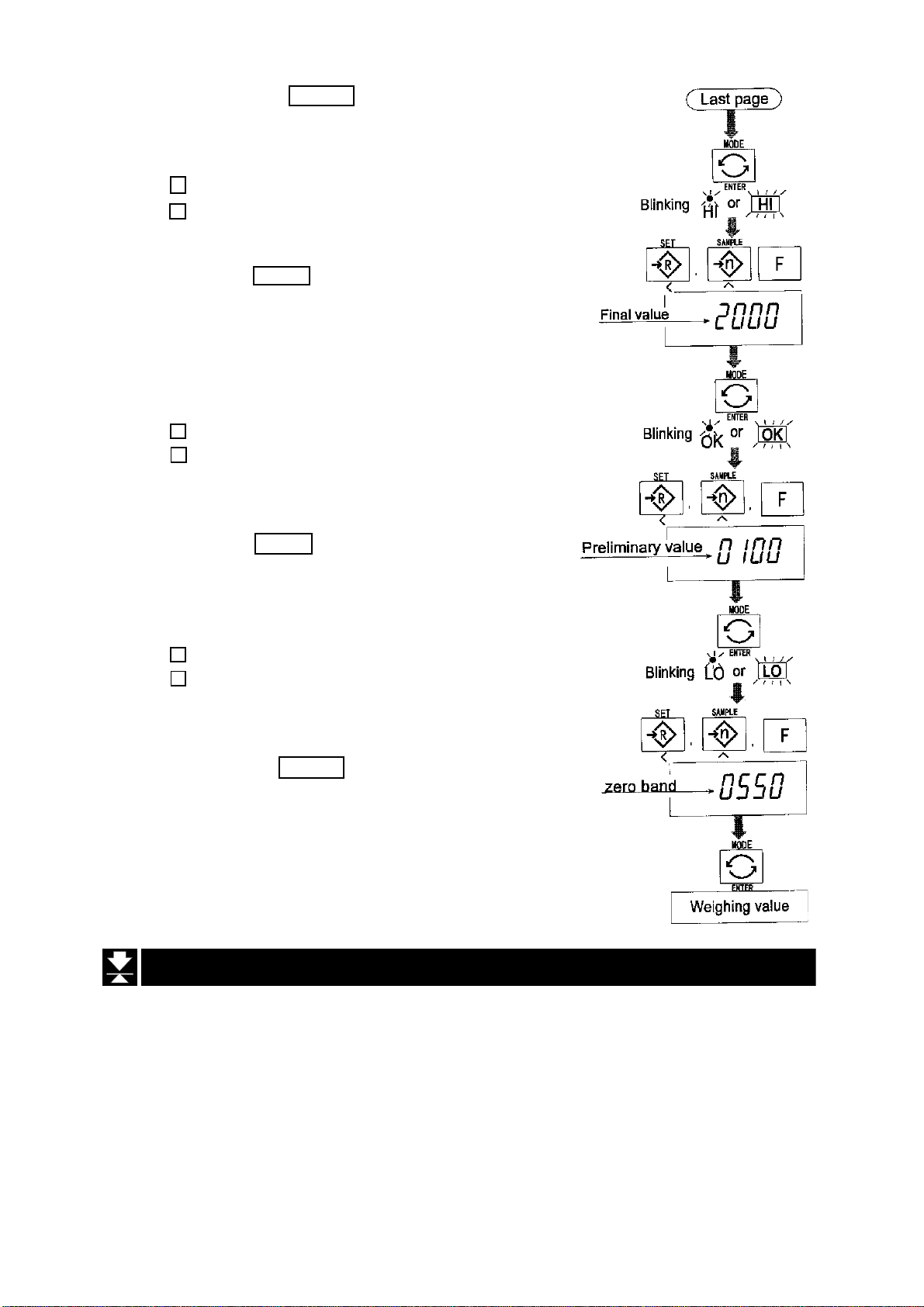
Step 8 Press the MODE switch to display the HI,
flashing, (of the final value).
Step 9 Set the final value using the following
switches:-
^ switch Selecting the value of a digit.
< switch Selecting a digit.
Step 10 Press the ENTER switch to store the new
parameter and display the blinking OK
(of preliminary value).
Step11 Set the preliminary value using the following
switches.
^ switch Selecting the value of a digit.
< switch Selecting a digit.
Step12 Press the ENTER switch to store the new
parameter and display the blinking LO
(of zero band).
Step13 Set a zero band which is greater than the
tare value, using the following switches.
^ switch Selecting the value of a digit.
< switch Selecting a digit.
Step14 Press the ENTER switch to store the new
parameter and display the weighing mode.
HW-G Instruction Manual Page 35
HW-G OZIM v1a
Page 38
13 Simple Batch Function
This function compares a display value with the final value, preliminary value and zero
band for the full/dribble batch function. The result is indicated to zero band (LO indicator),
full flow (HI indicator) and dribble flow (OK indicator). Even if a weighing value increases
and decreases this function continues to compare.
It is necessary to set the parameters of the “simple batch function ( f6 8 )” in the
function table, final value (HI), preliminary value (OK) and zero band (LO) in advance to
use this function.
It is necessary to install option OP-03 or OP-04, to use the relay output of the comparator.
It is necessary to install option OP-03, to use the buzzer output of the comparator.
Comparison Condition
Gross < Zero bandLO is displayed and output.
Final - Preliminary < Net OK is displayed and output.
Final < Net OK, HI is displayed and output.
Parameter List and Word Definition
The “gross” is a total measurement value, no tare value is subtracted.
The “net” is a measurement value with a tare value subtracted from the gross.
The “tare” is an item put on the pan and its mass is subtracted from the gross.
The “zero band” means the zero detection level.
The “zero point” is the fundamental starting point to weighing.
Function Table Meaning and purpose
f6 8 Simple batch function
HW-G OZIM v1a
HW-G Instruction Manual Page 36
Page 39

Caution
The parameters of the upper limit value (HI) and a final value (HI) use the same
memory. The parameters of the lower limit value (LO) and the zero band (LO) use
the same memory.
The upper/lower comparator function, the simple batch function and the full/dribble
batch function cannot be used at the same time because these parameters use
common memory.
13.1 Preparation (Setting Parameters)
Step 1 Turn off the display.
Press the ON/OFF switch while the ZERO switch
is pressed and held. The function table is displayed.
Step 2 Press the ENTER switch to display an item of the
comparator function ( f6 ).
Step 3 Select a parameter of the simple batch function
( f6 8 ) with the ^ switch.
Step 4 Press the ENTER switch to store the new
parameter.
Step 5 Press the F switch and the ENTER switch to exit
from the function table. Then the scale displays the
weighing mode.
HW-G Instruction Manual Page 37
HW-G OZIM v1a
Page 40
Step 6 Press the MODE switch to display the
HI, blinking. (Final value).
Step 7 Set the final value using the following switches.
^ switch Selecting the value of a digit.
< switch Selecting a digit.
Step 8 Press the ENTER switch to store the new
parameter and display the OK, blinking,
(Preliminary value).
Step 9 Set the preliminary value using the following
switches.
^ switch Selecting the value of a digit.
< switch Selecting a digit.
Step10 Press the ENTER switch to store the new
parameter and display the LO, blinking, (Zero
band).
Step1 1 Set the zero band using the following switches.
^ switch Selecting the value of a digit
< switch Selecting a digit.
Step 12 Press the ENTER switch to store the new
parameter and display the weighing mode.
13.2 Operation and Performance (Examples)
Step 1 Select the parameter f6 8 of the function table.
Step 2 Set the parameters of the final value, preliminary value and zero band.
Step 3 The comparison result is always displayed.
HW-G OZIM v1a
HW-G Instruction Manual Page 38
Page 41

14 Calibration (Adjusting the Scale)
Calibration is the adjustment function so that the scale can weigh correctly.
There are three steps to calibration.
Gravity Acceleration Correction ....When a calibrated scale is moved to a
distant place, the scale can correctly weigh
by adjusting to a new local gravity
acceleration.
Refer to the “gravity acceleration table” on
the next page.
Calibration of the Zero Point........ When there is nothing on the pan, it is the
function that performs adjustment so as to
display the zero point mark .
Comment
Span Calibration .......................... The function that adjusts the span with a
Comment Span means the range of weighing
The zero point, is the fundamental starting
point to weighing, and influences the
performance of the scale.
calibrated mass so that the scale can
accurately weigh anything within the
weighing capacity.
capacity. Use a calibration mass at least two
thirds of the weighing capacity.
Caution
It is necessary to calibrate the HW-G series using a mass of OIML class M1 or
equivalent.
Periodically check the accuracy of weighing. Calibrate the scale if it is moved to
another location or the environment has changed.
It is not necessary to correct for the gravity acceleration when calibrating your
scale, with the calibration mass, at the place where your scale is used.
HW-G Instruction Manual Page 39
HW-G OZIM v1a
Page 42
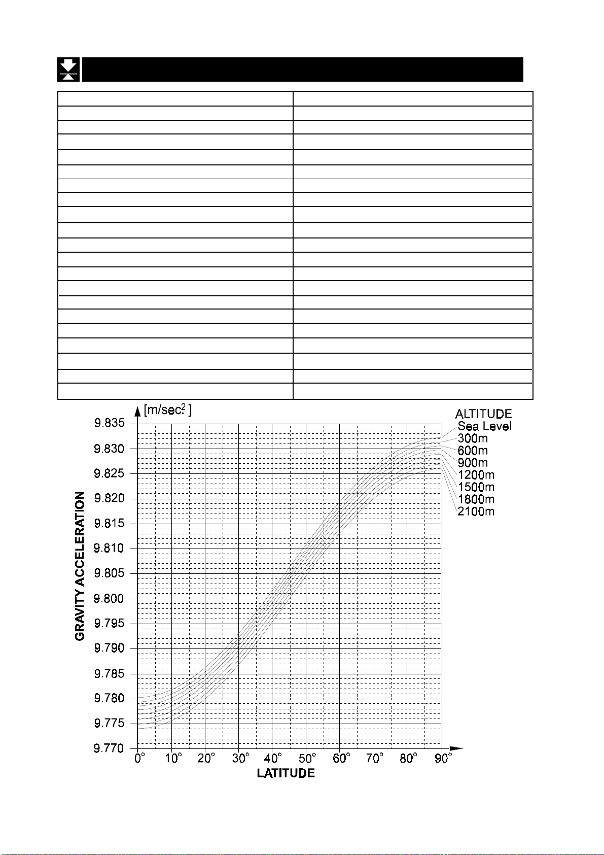
14.1 The Gravity Acceleration Table
Amsterdam 9.813 m/s
Athens 9.800 m/s
Auckland NZ 9.799 m/s
Bangkok 9.783 m/s
Birmingham 9.813 m/s
Brussels 9.811 m/s
Buenos Aires 9.797 m/s
Calcutta 9.788 m/s
Chicago 9.803 m/s
Copenhagen 9.815 m/s
Cyprus 9.797 m/s
Djakarta 9.781 m/s
Frankfurt 9.810 m/s
Glasgow 9.816 m/s
Havana 9.788 m/s
Helsinki 9.819 m/s
Kuwait 9.793 m/s
Lisbon 9.801 m/s
London (Greenwich) 9.812 m/s
Los Angeles 9.796 m/s
Madrid 9.800 m/s
2
2
2
2
2
2
2
2
2
2
2
2
2
2
2
2
2
2
2
2
2
Manila 9.784m/s
Melbourne 9.800m/s
Mexico 9.779m/s
Milan 9.806m/s
New York 9.802m/s
Oslo 9.819m/s
Ottawa 9.806m/s
Paris 9.809m/s
Rio de Janeiro 9.788m/s
Rome 9.803m/s
San Francisco 9.800m/s
Singapore 9.781m/s
Stockholm 9.818m/s
Sydney 9.797m/s
Taiwan 9.788m/s
Taipei 9.790m/s
Tokyo 9.798m/s
Vancouver, BC 9.809m/s
Washington DC 9.801m/s
Wellington NZ 9.803 m/s
Zurich 9.807m/s
2
2
2
2
2
2
2
2
2
2
2
2
2
2
2
2
2
2
2
2
2
HW-G OZIM v1a
HW-G Instruction Manual Page 40
Page 43

14.2 The Complete Calibration Procedure
14.2.1 Gravity Acceleration Correction
Step1 Turn on the display.
Open the rear cover of the display unit.
Inside the display unit, press and hold the
CAL switch to enter the calibration mode.
Then Cal 0 is displayed.
Step2 Press the ZERO switch to enter the gravity
acceleration correction mode.
Step3 Set your local gravity acceleration using
the following switches.
^ switch Selecting the value of a digit.
< switch Selecting a digit.
Step4 Press the ENTER switch to store the new
value.
Step5 Press the CAL switch again. Then the
scale returns to the normal weighing
mode.
14.2.2 Preparation
Step 6 Confirm the environmental conditions as follows:
Maintain a constant temperature and a stable power supply.
Install the scale on a solid floor or bench where there is no draft,
vibration, strong magnetic fields or direct sunlight.
Consider section “4. Caution”.
Step 7 Display normal weighing for at least 30 minutes to warm up the scale.
HW-G Instruction Manual Page 41
HW-G OZIM v1a
Page 44
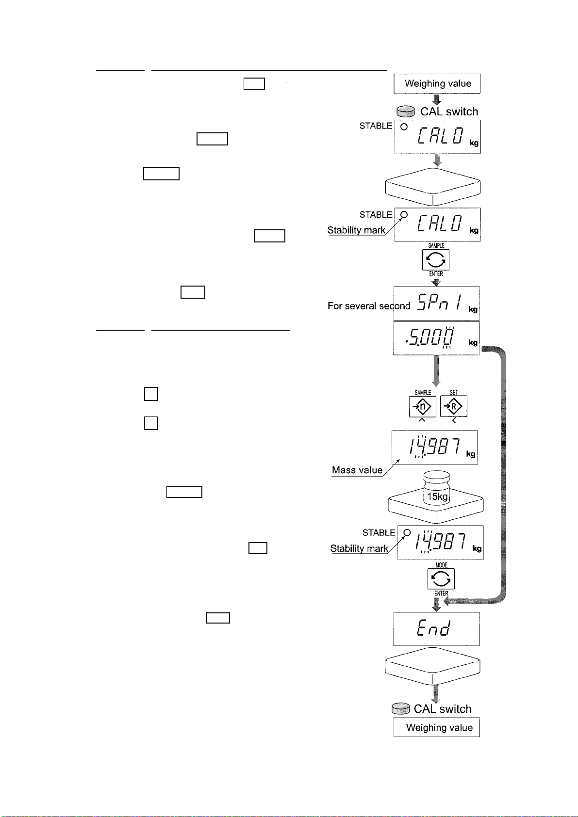
14.2.3 Calibration of the Zero Point
Step 8 Press and hold the CAL switch to
enter the calibration mode after
displaying normal
weighing for 30 minutes.
Then the Cal 0 is displayed.
Step 9 With n othin g on th e pan, press the
ENTER switch while the stable
mark is displayed. The scale
stores the current condition as the
zero point. .
Step 10 The scale displays 5pn1 for
several seconds. If finishing
the calibration mode at this
stage (Zero calibration only),
press CAL to proceed to step 13.
14.2.4 Span Calibration
Step 11 Set the value of the calibration
mass using the following switches.
(The initial value depends upon the
particular model.)
^ switch Selecting the value of
a digit.
< switch Selecting a digit.
Step 12 Place the mass’ selected at
step 11’ onto the pan. When the
stable mark is displayed press
the ENTER switch.
The scale then calculates the
span and stores the value.
Step 13 The scale displays end at the
finish.
Remove the mass from the pan.
Step 14 Press the CAL switch to return
to the normal weighing mode.
HW-G OZIM v1a
HW-G Instruction Manual Page 42
Page 45
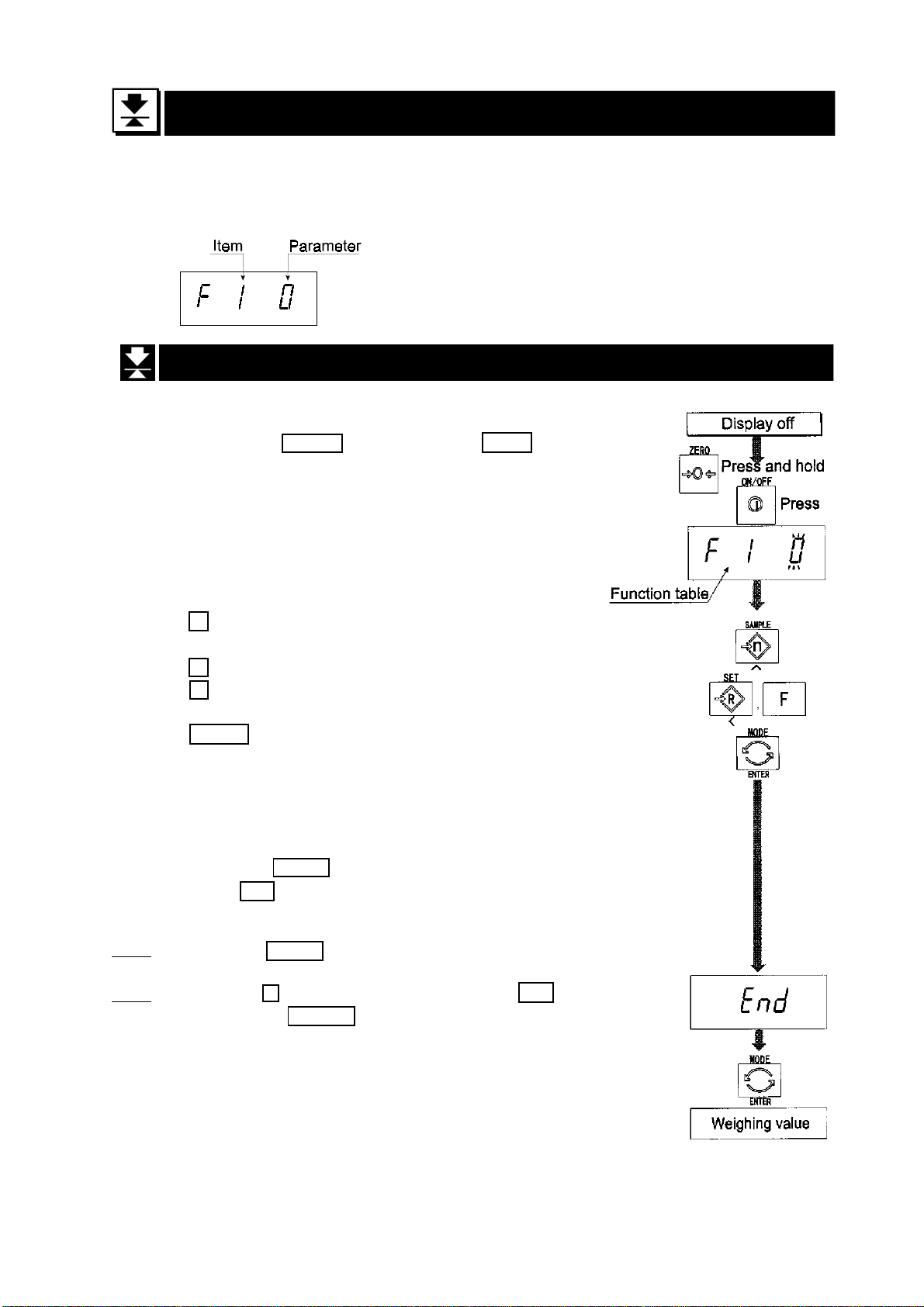
15 The Function Table
The function table is provided to store and reference items that determine the
performance of the scale. Each item has a parameter.
The parameters are maintained even without power applied.
15.1 The Procedure for Setting Parameters
Step 1 Turn off the display.
Press the ON/OFF switch while the ZERO switch is
pressed and held. The function table is displayed.
Step 2 Set parameters for each item using the following
switches.
^ switch Selecting the parameter of an item.
Selecting the value of a digit at f16.
< switch Selecting a digit at f16.
F switch Proceeding to the end of the table
without storing the parameter.
ENTER switch Storing a parameter for the current
item and proceeding to the next item.
Returning to normal mode from the
end of the table.
Step 3 Press the ENTER switch to return to the normal mode,
when end is displayed.
Note Pressing the ENTER switch on step 2, the parameter is
stored in the scale.
Note Pressing the F switch at any time will cause end to be
displayed. The press ENTER to return to the normal mode.
HW-G Instruction Manual Page 43
HW-G OZIM v1a
Page 46
15.2 Parameter List
Item Display Meaning and purpose ?
The type L scale is turned off after 5 minutes of no operation,
when displaying zero.
Automatic f1 0 # Not used ?
turning off f1 1 Used??
Transmission rate of the serial interface (RS-232C/ 422/485).
f4 0 # 2400bps ?
Baud rate f4 1 4800bps ?
f4 2 9600bps ?
Mode selection for the serial interface (RS-232C/ 422/485).
f5 0 # Stream mode. (Refer to “16.2 Stream Mode”) ?
f5 1 Command mode. (Refer to “16.3 Command Mode”) ?
f5 2 A data is output, when the PRINT switch is pressed. ?
f5 3 Auto-print +
When the display becomes a positive stable value above
near-zero, the scale outputs the data automatically. Next
Output mode output can be performed after the display becomes near-
zero or a negative value. ?
? f5 4` Auto-print +/-
When the display becomes a stable value outside near-zero,
the scale outputs the data automatically. Next output can be
performed after the display becomes near-zero.?
? f5 5 At each finish of full/dribble batch function, the data is output. ?
Mode selection for the comparator
f6 0 # Pressing the SET switch, the scale always compares the
current display value. A
A
Comparator f6 2 Pressing the SET switch, the scale always compares the
Notes
The “#” shows factory settings.
The “near-zero” is within ±4 digits from zero point in the unit of kg.
f6 1 The scale always compares the display value. A
display value when not near-zero. A
f6 3 The scale always compares the display value when not
near-zero.A
HW-G OZIM v1a
HW-G Instruction Manual Page 44
Page 47
Item Display Meaning and purpose ?
Comparator When the display value becomes stable after pressing the
SET switch, the scale compares the display value. It does not
f6 4 compare on an unstable condition. If the SET switch is pressed
again, the scale stops the comparison.
When the display value becomes stable, the scale compares
f6 5 the display value. It does not compare on an unstable
condition.
When the display value becomes stable and not near-zero
after pressing the SET switch, the scale compares the display
f6 6 value. It does not compare on an unstable condition. If the SET
switch is pressed again, the scale stops the comparison.
f6 7 When the display value becomes stable when not near-zero,
the scale compares the value.
f6 8 Simple batch function. (Refer to section 13.)
f6 9 Full/dribble batch function. (Refer to section 12.)
Buzzer
The condition of the buzzer on option OP-03 by comparator
function or full/dribble batch function.
f7 0 # No buzzer.
f7 1 The buzzer sounds at LO.
f7 2 The buzzer sounds at OK.
f7 3 The buzzer sounds at LO and OK.
f7 4 The buzzer sounds at HI.
f7 5 The buzzer sounds at LO and HI.
f7 6 The buzzer sounds at OK and HI.
f7 7 The buzzer sounds at LO, OK and HI.
f7 8 The buzzer sounds at finishing the full/dribble batch process.
Accumulator
The condition of the accumulator
f8 0 # Accumulator is not used.
The scale accumulates the data, if the F switch is pressed,
f8 1 when the display becomes a positive stable value above
near-zero. Next accumulation can be performed after the
display becomes near-zero or a negative value.
The scale accumulates the data, if the F switch is pressed,
f8 2 when the display becomes a stable value outside near-zero.
Next accumulation can be performed after the display be
comes near-zero.
When the display becomes a positive stable value, the scale
f8 3 accumulates the data automatically. Next accumulation can
be performed after the display becomes near-zero or a
negative value.
HW-G Instruction Manual Page 45
HW-G OZIM v1a
Page 48

Item Display Meaning and purpose
Accumulation When the display becomes a stable value, the scale
accumulates the data automatically. Next accumulation can
occur after the display becomes near-zero.
f8 4 Use: Recording number and mass of articles removed from
the pan. (Put articles on the pan. Press TARE switch at each
removal.)
At each finish of full/dribble batch function, the scale
accumulates the data automatically.
f8 5 Use: Packing articles like a powder, it is used for recording
the bag number and total mass.
The printing condition when using option OP-06 for type V.
f9 0 # No print.
f9 1 Pressing the PRINT switch, the data is output.
Auto-print +
When the display becomes a positive stable value above
f9 2 near-zero, the scale outputs the data automatically. Next
output can be performed after the display becomes nearzero or negative value.
Print Mode Auto-print +/-
When the display becomes a stable value outside near-zero,
f9 3 the scale outputs the data automatically. Next output can be
performed after the display becomes near-zero.
f9 4 At each finish of full/dribble batch function, the data is output.
f9 5 When the accumulation function is used, the data is output.
The details of the full/dribble batch function (
B$'
)
f10 0 # Reaching final value and pressing the F switch, the current
process is finished.
f10 1 Reaching final value and displaying the stability mark, the
current process is finished automatically.
f10 2 Pressing the SET switch, the scale automatically tares and
starts the full/dribble batch process. Reaching final value and
pressing the F switch, the current process is finished.
Full/Dribble f10 3 Pressing the SET switch, the scale automatically tares and
Batch starts the full/dribble batch process. Reaching final value and
sub-function displaying the stability mark, the current process is finished.
Address for RS-422 / RS-485 for option OP-04
f11 00 # Use This address can be set from 01 to 99. Allows a
Address to computer to control a scale with the assigned address.
f11 99 (RS-232C should be set to “00”.)
?
HW-G OZIM v1a
HW-G Instruction Manual Page 46
Page 49
Item Display Meaning and purpose
The function to hold the current display value. When the
value becomes near-zero and the weighing value changes
more than 25% +30 digits, hold display is cancelled.
Hold f12 0 # Not used
f12 1 The hold function is ON or OFF alternately by the F switch.
f12 2 Displaying the stability mark, the display is held.
Selection of readability and response by averaging the weighing
value.
Averaging f13 0 # Normal weighing.
f13 1 Scale for a person’s weight.
f13 2 Animal weighing.
Selects a storable minimum unit mass in the counting mode.
Precision f14 0 # Stores a unit mass using the unit of a digit.
of f14 1 Stores a unit mass in the unit of one eighth digit.
unit mass f14 2 Stores a unit mass, if the total of sample mass is heavier
than 5 digits.
Refer to “16.1. Data Format”.
Data f15 0 # Format 1. (A&D general format for scales, balances)
Format f15 1 Format 2. (Older HV-A/ HW-A format)
It is necessary to use option OP-06 for type V.
Use Print out of date. Caution Date is not updated.
Print out of the management number for the scale.
Date f16 No print out.
000000
The relation between printout and display is as follows:
other Display 990721
Printout 99/07/21
HW-G Instruction Manual Page 47
HW-G OZIM v1a
Page 50

16 RS-232C Serial Data Interface
RS-232C interface has the following two modes.
Stream mode Outputs data countinuously and can be used for printing data.
Command mode Controls the scale using commands from a computer.
It is necessary to set the parameters of the “Baud rate ( f4 )”,
”Output mode ( f5 )”, “ Format ( f15 )” in the function table in advance.
There are option cables as follows:
AX-KO557ARS-232C cable, D-sub 25 pin, 2m
AX-KO1786-200 RS-232C cable, D-sub 9 pin, 2m
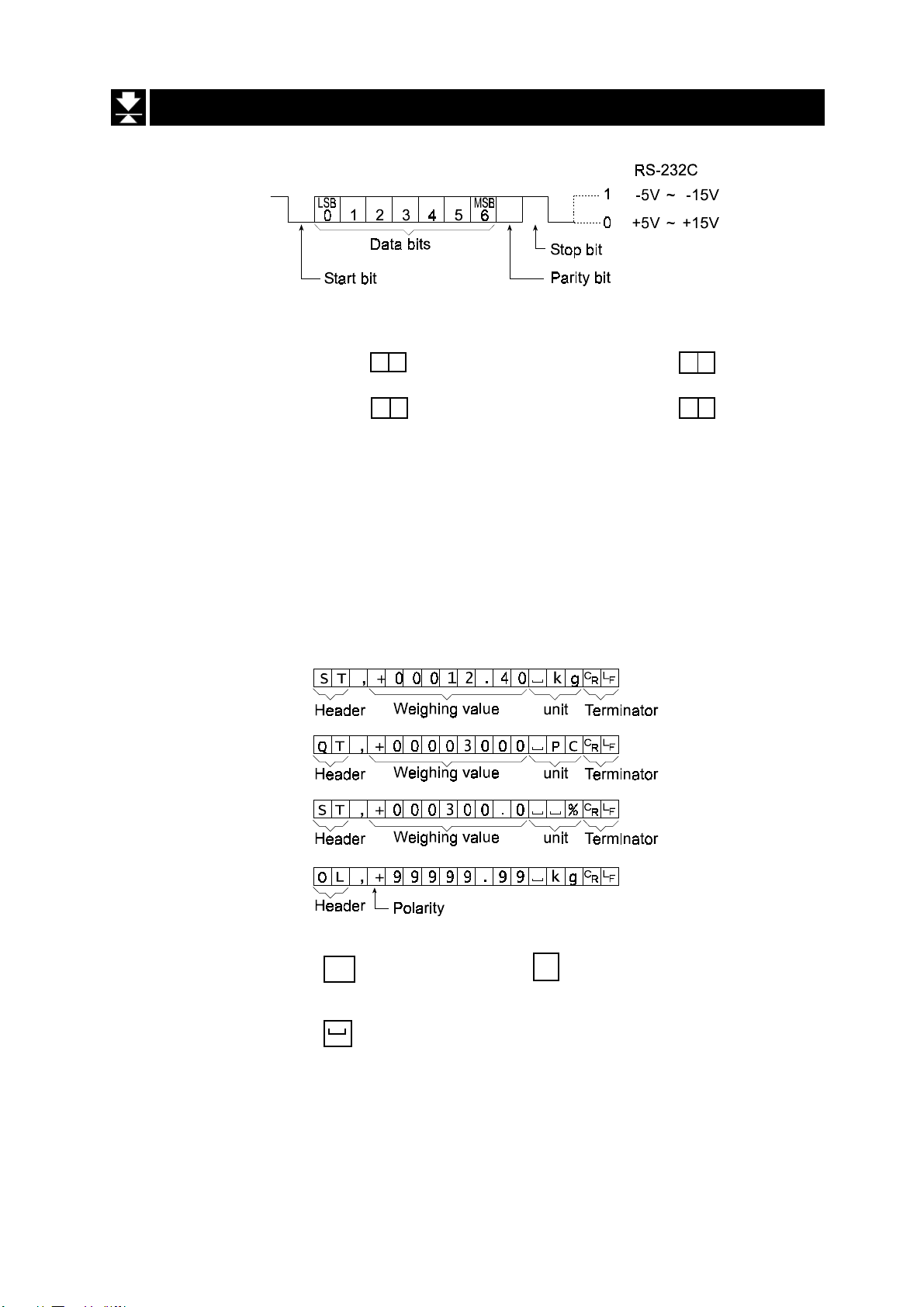
Transmission system EIA RS-232C
Transmission Asynchronous, bi-directional, half-duplex
Data format Baud rate:2400, 4800, 9600 bps
Data: 7 bits
Parity: 1 bit, Even
Start bit 1 bit
Stop bit 1 bit
Code ASCII
Terminator CR LF (CR: 0D[H], LF: 0A[H])
Pin Connections
Pin No. Signal name Direction Description
12 RXD Input Receive data
3 TXD Output Transmit data
45 SG - Signal ground
67 DSR Output Data set ready
Circuit
HW-G OZIM v1a
HW-G Instruction Manual Page 48
Page 51
16.1 Data Format
Bit Format
Format 1
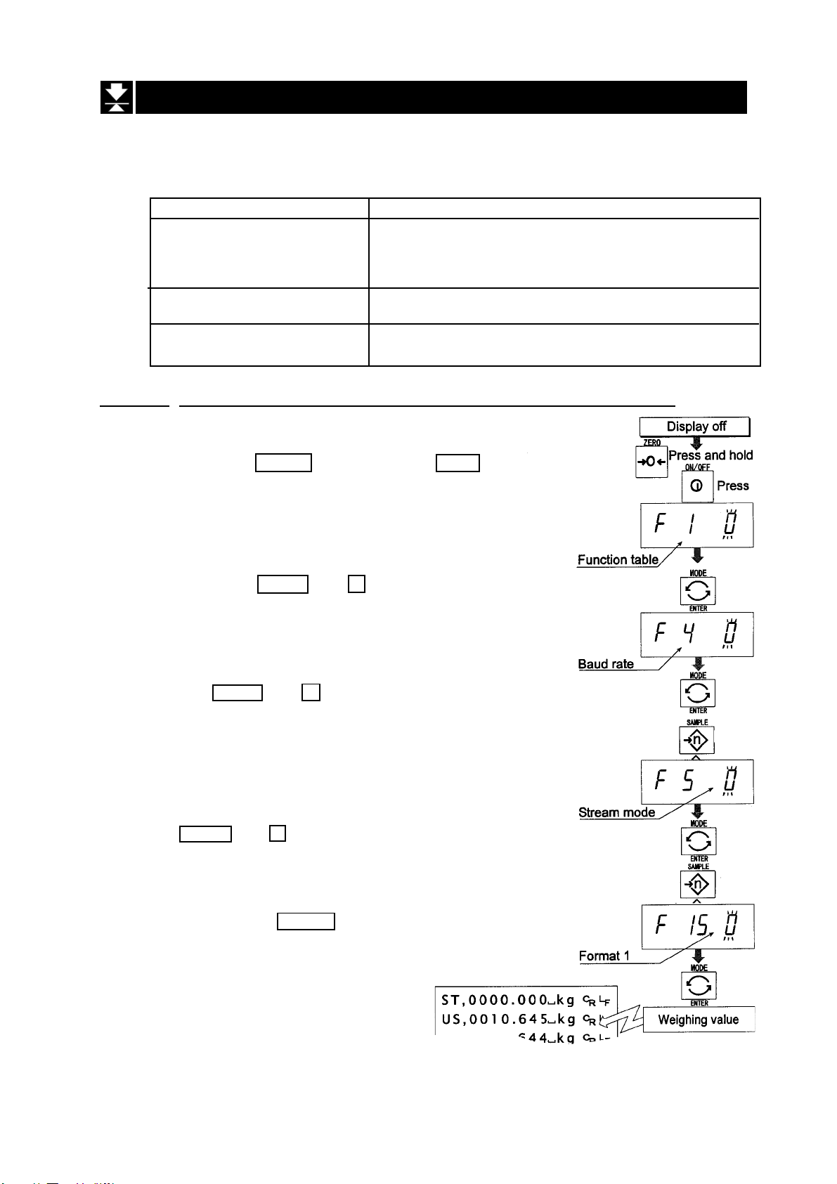
There are four headers for the type of data and weighing condition.
Stable weighing data S T Unstable weighing data U S
Stable counting data Q T Out of range (over) O L
The weighing data consists of 9 characters including decimal point and polarity.
The polarity is always output.
There are three units. The unit is 3 characters.
In case of “out of range”, numbers become all 9’s.
The terminator is always output as CR LF.
Data in the unit of kg
Counting mode
Percentage mode
Out of range
Definition of symbols
CR (carriage return)
C
R
LF (line feed)
0D[H] 0A[H]
Space
20[H]
L
F
HW-G Instruction Manual Page 49
HW-G OZIM v1a
Page 52

Format 2
There are four headers for the type of data and weighing condition.
Stable weighing data S T Unstable weighing data U S
Stable counting data Q T Out of range (over) O L
The weighing data consists of 7 characters including decimal point and polarity.
The data consists of 7 characters in the counting mode.
The polarity is always output.
There are three units. The unit is 2 characters.
In case of “out of range”, numbers become all 9’s.
The terminator is always output as CR LF.
Caution
When the data is longer than 7 characters in the counting or percentage mode, the
overflow is ignored.
Data in the unit of kg
Counting mode
Percentage mode
Out of range
Definition of symbols
CR (carriage return)
C
R
LF (line feed)
0D[H] 0A[H]
Space
20[H]
L
F
HW-G OZIM v1a
HW-G Instruction Manual Page 50
Page 53
16.2 Stream Mode
The scale outputs the current display data at the same time as refreshing the display.
The scale does not output data while in the setting mode.
Averaging function table Refresh rate
f13 0 Normal weighing Approximately 7 times/s while the display is
unstable.
Approximately 4 times/s when the display is stable
f13 1 A person’s weight Approximately 4 times/s
f13 1 Animal weighing Approximately 4 times/s
16.2.1 Preparation and Performance (Examples)
Step 1 Turn off the display.
Press the ON/OFF switch while the ZERO switch is
pressed and held. The function table is displayed.
Step 2 Select a parameter for the “baud rate ( f4 )”
using the ENTER and ^ switches.
Step 3 Select “stream mode ( f5 0 )” of “output” using
the ENTER and ^ switches.
Step 4 Select “format 1 ( f15 0 )” of “format” using the
ENTER and ^ switches.
Step 5 Press the ENTER switch to store the new
parameters. The scale returns to normal weighing
and outputs the data continuously.
HW-G Instruction Manual Page 51
HW-G OZIM v1a
Page 54

16.3 Command Mode
The command mode is the function which can perform “output data”, “controlling the scale”
and “setting parameters” by a command transmitted from a computer.
Caution Allow at least 500 milliseconds between commands.
16.3.1 Command List
The following explanation uses “format 1 ( f15 0 )”
Data output
The current weighing data is output.
Template Q
Command
Reply
Selection of mode and unit
Selects the mode and unit. This is the same as the
Template U
Command
Response The scale changes mode and unit.
MODE
switch.
Zero
The current mass value is set to the zero point.
This is same as the ZERO switch.
Template Z
Command
Response The mass value becomes zero and zero point mark is displayed.
Tare
The current mass value is set to zero after placing a tare (container, receptacle,
case, etc) and the net is displayed. This is the same as the
Template T
Command
Response The current mass value becomes zero and net mark is displayed.
TARE
switch.
Cancel of tare
The display value becomes the gross and the net mark is turned off. (The tare
value becomes zero.)
Template CT
Command
Response Gross is displayed and the net mark is turned off.
HW-G OZIM v1a
HW-G Instruction Manual Page 52
Page 55

Preset tare
Tare value is set and the net is displayed. The net mark is displayed.
Template PT, [parameter]
Command
Response Net is displayed.
Upper limit value
An upper limit value is stored.
Template HI, [parameter]
Command
Response The upper limit value is stored.
Lower limit value
A lower limit value is stored.
Template LO, [parameter]
Command
Response The lower limit value is stored.
Caution The lower limit value must be less than the upper limit value.
Accumulation data output
Accumulated data is output.
Template A
Command
Reply
Accumulation count output
Number of accumulations is output.
Template N
Command
Reply
Reset of Accumulation data and number
Data and number of accumulations become zero
Template CA
Command
Response Data and number of accumulations become zero.
HW-G Instruction Manual Page 53
HW-G OZIM v1a
Page 56
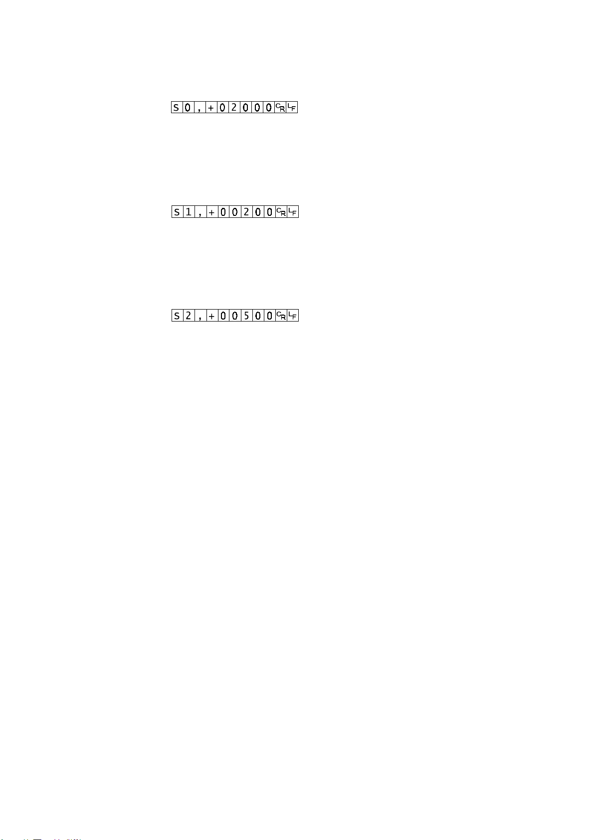
Final value
The final value is stored.
Template S0, [parameter]
Command
Response The value is stored.
Preliminary value
The preliminary value is stored.
Template S1, [parameter]
Command
Response The value is stored.
Zero band
The zero band is stored.
Template S2, [parameter]
Command
Response The value is stored.
HW-G OZIM v1a
HW-G Instruction Manual Page 54
Page 57

16.4 Preparation (Setting Parameters)
Step 1 Turn off the display.
Press the ON/OFF switch while the ZERO switch is
pressed and held. The function table is displayed.
Step 2 Select a parameter of the “baud rate ( f4 )” using
the ENTER and ^ switches.
Step 3 Select “command mode ( f5 1 )” of the “output”
using the ENTER and ^ switches.
Step 4 Select “format 1 ( f15 0 )” of the “format” using
the ENTER and ^ switches.
Step 5 Press the ENTER switch to store the new
parameters.
Return to the normal weighing mode using the
ENTER switch.
Step 6 Receiving a command, the scale responds.
HW-G Instruction Manual Page 55
HW-G OZIM v1a
Page 58

17 Options
17.1 RS-232C / Relay output / Buzzer (OP-03)
Replacing RS-232C interface with this option, refer to “ RS-232C Serial Interface” for its
specification.
The following option cables can be used, when you do not use the relay output.
AX-KO557A, AX-KO1786-200
Pin connections
Pin No. Signal name Direction Description
1 HI Output Relay output of HI
2 RXD Input Receive data
3 TXD Output Transmit data
4 LO Output Relay output of LO
5 SG - Signal ground (RS-232C)
6 OK Output Relay output of OK
7 DSR Output Data set ready
8 COM - Relay common terminal
Mating connector DIN 8pin, JA:TCS0586 (of accessory pack)
Circuit
Relay Solid-state-relay Maximum voltage DC50V
Maximum current DC100mA
Maximum ON resistance 8 Ω
Installing OP-03
Step 1 Remove two screws that
attach the RS232C board on
the rear of the display unit.
Remove the RS232C board.
Step 2 Switch the connections.
Step 3 Insert the option board into the
display unit and afix with
screws
HW-G OZIM v1a
HW-G Instruction Manual Page 56
Page 59

17.2 RS-422 / RS-485 / Relay output (OP-04)
Replacing RS-232C interface with this option, the RS-422/ RS-485 interface can connect
up to 16 scales and control them from a computer.
The RS-422/ RS-485 interface has the following two modes.
Stream mode Outputs data countinuouslly.
Command mode Controls the scale using commands from a computer.
It is necessary to set the parameters of the “Baud rate ( f4 )”, “
Output mode ( f5 )”, “ Format ( f15 )” in the function table in advance.
Transmission systemEIA RS-422/ RS-485
Transmission Asynchronous, bi-directional, half-duplex
Data format Baud rate:2400, 4800, 9600 bps
Data: 7 bits
Parity: 1 bit, Even
Start bit 1 bit
Stop bit 1 bit
Code ASCII
Terminator CR LF (CR: 0D[H], LF: 0A[H])
Address 01 ~ 99 Address parameter ( f10 ) of function table.
Relay Solid-state-relay
Maximum voltage DC50V
Maximum current DC100mA
Maximum resistance 8 Ω
Mating connector TM:BLA9 (of accessory pack)
Pin connections
Pin No. Signal name Direction Description
1 SDA Output RS-422 transmission A terminal
2 SDB Output RS-422 transmission B terminal
3 RDA Input RS-422 receive A terminal
Input / Output RS-485 transmission/ receive A
terminal
4 RDB Input RS-422 receive B terminal
Input / Output RS-485 transmission/ receive B
terminal
5 TRM - 120Ω terminator
6 HI Output Relay output of HI
7 OK Output Relay output of OK
8 LO Output Relay output of LO
9 COM - Relay common terminal
HW-G Instruction Manual Page 57
HW-G OZIM v1a
Page 60
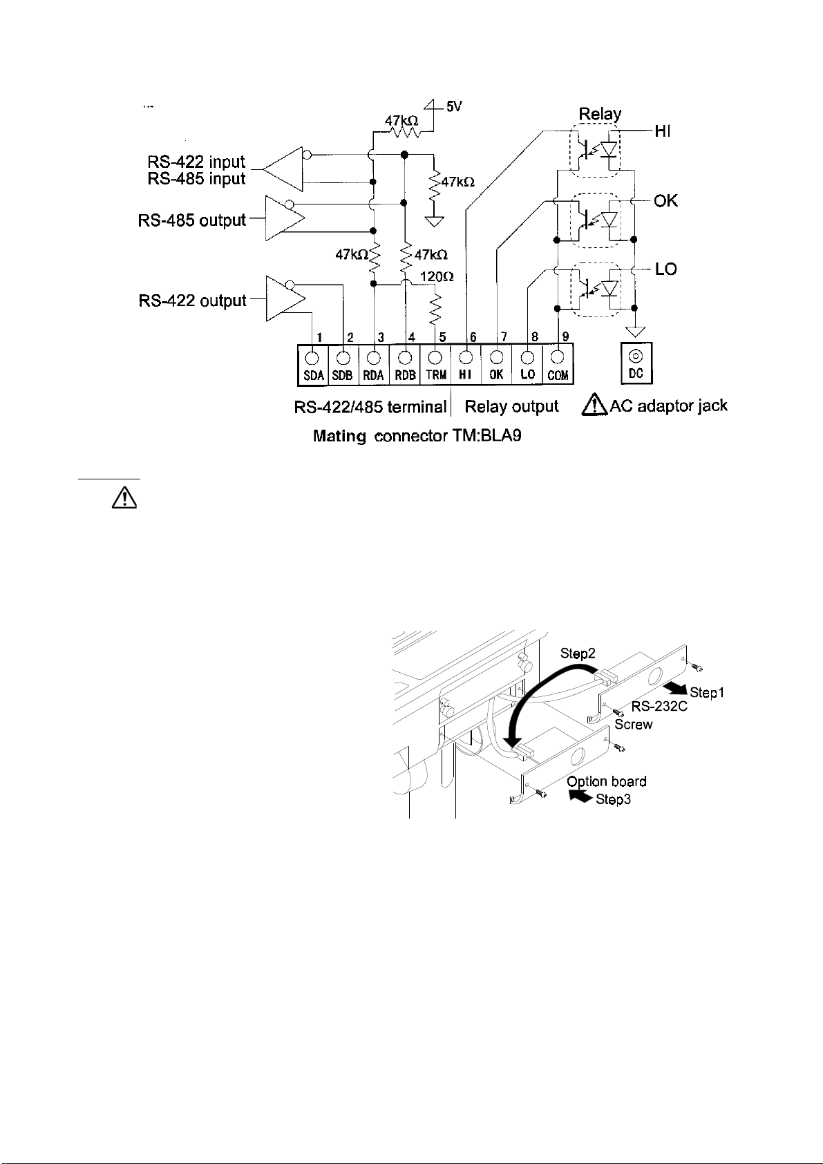
Circuit
Caution
Please confirm that the AC adaptor type is correct for your local voltage
and receptacle type.
Selection switch for the RS-422/ RS-485 interface
Selects either of RS-422 or RS-485 interface using a switch on the board.
Installing OP-04
Step 1 Remove two screws that
attach the RS232C board on
the rear of the display unit.
Remove the RS232C board.
Step 2 Switch the connections.
Step 3 Insert the option board into the
display unit and afix with the
screws
HW-G OZIM v1a
HW-G Instruction Manual Page 58
Page 61
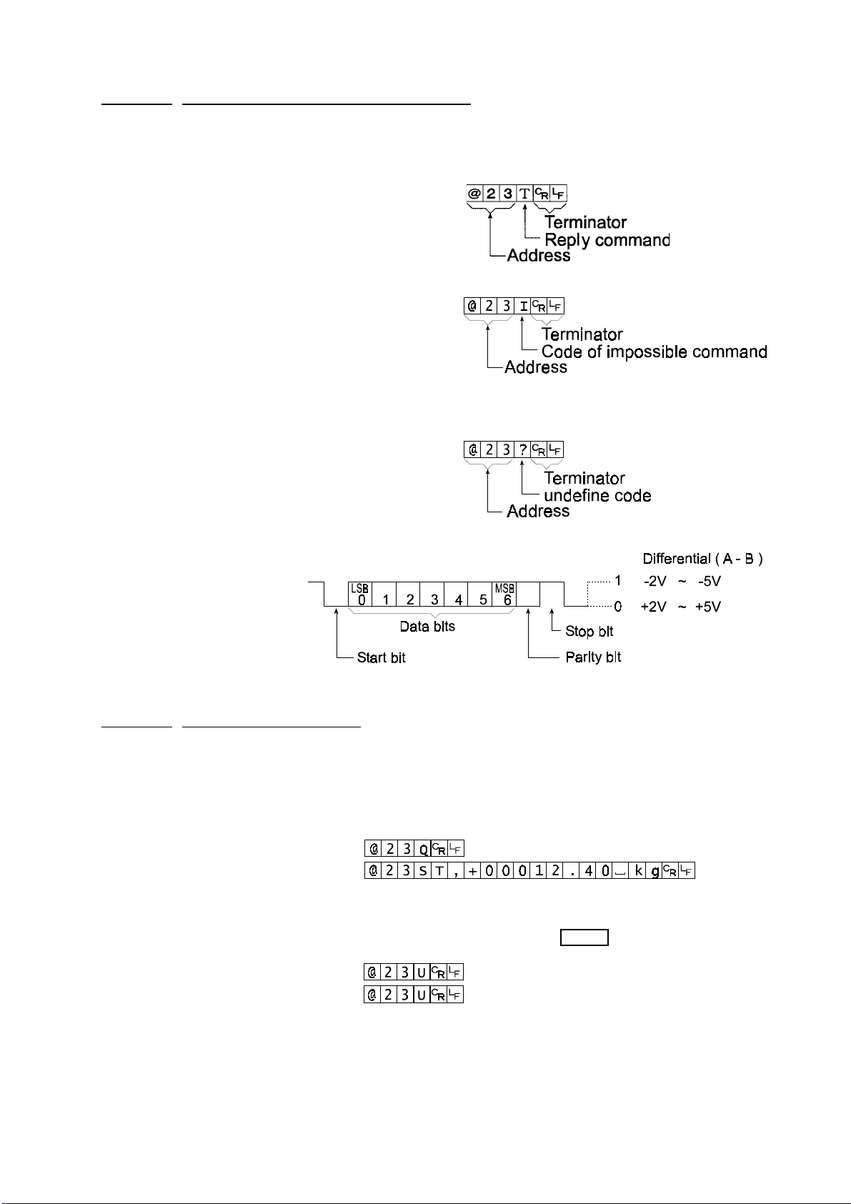
17.2.1 Communication Format
Commands consist of an address and the same command as for the RS-232C.
Commands return the same command when there is no transmitting data.
If address is 23, the repl y is as follows:
Normal response
Response of impossible command
Undefined command response
Bit format
17.2.2 Command List
The following explanation uses “format 1 ( f15 0 )” and assumes address is 23
Data output
The current weighing data is output.
Template Q
Command
Reply
Selection of mode and unit
Selects the mode and unit. This is same as the
Template U
Command
Reply
The scale changes mode and unit
MODE
switch.
HW-G Instruction Manual Page 59
HW-G OZIM v1a
Page 62

Zero
The current mass value is set to the zero point, this is same as the
Template Z
Command
Reply
The mass value becomes zero and zero point mark is displayed.
ZERO
Tare
The current mass value becomes zero after placing a tare (receptacle, case, etc)
and the net is displayed. This is same as the
Template T
Command
Reply
The current mass value becomes zero and net mark is displayed.
TARE
switch
.
Cancel of tare
The display value becomes the gross and the net mark is turned off. (The tare value
becomes zero.)
Template CT
Command
Reply
Gross is displayed and the net mark is turned off.
switch.
Preset tare
The tare value is set and the net is displayed. The net mark is displayed.
Template PT,[parameter]
Command
Reply
Net is displayed.
Upper limit value
An upper limit value is stored.
Template HI,[parameter]
Command
Reply
The upper limit value is stored.
Lower limit value
A lower limit value is stored.
Template LO, [parameter]
Command
Reply
The lower limit value is stored.
Caution The lower limit value must be less than the upper limit value.
HW-G OZIM v1a
HW-G Instruction Manual Page 60
Page 63

Accumulation data output
Accumulated data is output.
Template A
Command
Reply
Accumulation count output
Number of accumulations is output.
Template N
Command
Reply
Reset of Accumulation data and number
Data and number of accumulations become zero.
Template CA
Command
Reply
Data and number of accumulations become zero.
Final value
The final value is stored.
Template S0, [parameter]
Command
Reply
The value is stored.
Preliminary value
The preliminary value is stored.
Template S1, [parameter]
Command
Reply
The value is stored.
Zero band
The zero band is stored.
Template S2, [parameter]
Command
Reply
The value is stored
HW-G Instruction Manual Page 61
HW-G OZIM v1a
Page 64

17.3 Internal Printer for Type V (OP-06)
It is necessary to set the parameter of the “Print mode ( f9 )” in the function table in
advance.
It is necessary to set the parameter of the “Date ( f16 )” on the function table in advance.
Caution The date Parameter is not updated automatically.
Specification
Kind 5x7 dot matrix impact type
Characters 16 characters per line
Width of roll paper 44.5mm
Accessories a special roll paper, an ink ribbon
Consumables
Special roll paper AX-PP156-S (Including 8 rolls in a set)
Ink ribbon AX-ERC-05-S (Including 5 pieces in a set)
Operation and Print Samples
Pressing the F switch while pressing and holding the PRINT switch, paper feed is
performed.
Print sample of selecting print mode f9 1
~ f9 4
Print sample of selecting print mode f9 5
99/12/31
001 1.345 kg
002 1.325 kg
1.330 kg
Print sample of displayed accumulation data
99/12/31
N 3
Total
7.810 kg
2.345 kg
2345pc
76.98%
HW-G OZIM v1a
HW-G Instruction Manual Page 62
Page 65

Installation of OP-06
Caution
This option cannot be used with type L (Liquid Crystal Display) scales.
Packed with the option OP-06 are the following items which are used to install the
printer into your scale.
Reference No. Description Quantity
6 Printer cover 1
7 Printer unit 1
8 Printer control board 1
a Self tapping screw 3
b Screw with washer 4
Paper roll (PP-156) 1
Spare ink ribbon (ERC-05) 1
Installation Method
1. Disassembly
a) Disconnect the scale power plug from the
AC mains supply socket.
b) Loosen the lock screws and remove the
rear cover unit (Item 3)
c) Loosen 4 x screws (Item c) and remove
the upper case unit.
d) Remove 2 screws (Item a) and remove
the Battery Cover.
2. Installation
(a) Connect CN2, of the printer board (Item 8),
to J5 on the main board (Item 1)
(b) Install the printer board (Item 8) to the
4 stand-offs on the board on the upper
case (Item 1).
(c) Secure the printer unit (Item 7) to the
upper case (Item 1).
(d) Connect the printer unit cable to CN4
on the printer board (Item 8).
HW-G Instruction Manual Page 63
HW-G OZIM v1a
Page 66
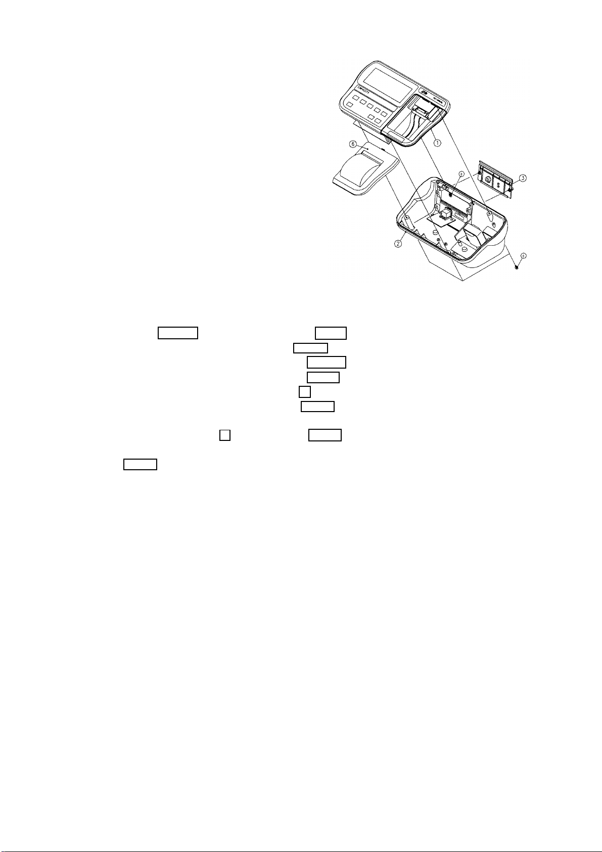
(a) Connect the cable between J2 and
J3 on the upper case (Item 1).
(b) Free the 2 pin cable on the lower
case (Item 2) and connect it to
CN1.
(c) Screw the upper case (Item 1) to
the lower case (Item 2) using the 4
screws (Items c).
(d) Secure the rear cover (Item 3) to
the lower case (Item 2) with the 2
lock screws.
(e)Secure the printer cover (Item 6 to
the upper case (Item 1).
3. Performance Check
a) Press ON/OFF key while holding the ZERO key pressed.
b) F1 will be displayed - press the MODE key.
c) F 9 0 will be displayed - press the RANGE key.
d) F 9 1 will be displayed - press the MODE key.
e) F10 will be displayed - press the F key
f) End will be displayed - press the MODE key.
g) Prepare the paper roll and open the printer cover.
h) While holding the F key, press the PRINT key and feed in the paper.
i) Place a weight onto the scale and when the stable mark flashes press the
PRINT key.
If the printed weight is correct then the installation has been successful.
HW-G OZIM v1a
HW-G Instruction Manual Page 64
Page 67

HW-G series
Product HW-10KGL HW-60KGL HW-100KGV HW-200KGV
HW-10KGV HW-60KGV HW-100KGL HW-200KGL
?
?
Weighing Capacity [kg] 10 60 100 220 ?
Min. weighing (1 digit) [g] 1 5 10 20
Number of samples in
counting mode [units] 5 can be changed to 10 20 50 100 ?
Max. count number [units] 10,000 12,000 10,000 11,000
?Display HW-GL 7 segment liquid crystal display, Character height 25mm
HW-GV 7 segment fluorescent display, Character height 20mm
Repeatability [g] ±2 ±10 ±20 ±40 ?
Linearity [g] ±2 ±10 ±20 ±40
Span drift 20ppm/°C typ. (5°C ~ 35°C) ?
Power source HW-GL AC adaptor Please confirm that the AC adaptor type
is correct for your local voltage and receptacle.
Battery x 6 pieces type ‘D’ ?
? HW-GV Please confirm that the Main power type is correct for your
local voltage and receptacle type. ?
?
Battery life (HW-GL) Approximately 600 hours with alkaline dry cell battery ?
Ambient temperature
and humidity -10°C ~ 40°C, Less than 85%R.H. (Non- condensing) ?
Weighing pan size [mm] 250 x 250 330 x 424 390 x 530 390 x 530 ?
Dimension [mm]
Width x Depth x Height 275 x 474 x 368 330 x 621 x 771 390 x 712 x 773 390 x 712 x 773
?
?Mass of scale [kg] HW-GL 6 11 17 17
HW-GV 7 12 18 18 ?
HW-G Instruction Manual Page 65
HW-G OZIM v1a
Page 68
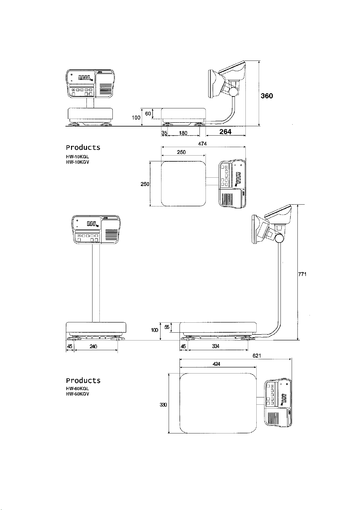
Dimensions
HW-G OZIM v1a
HW-G Instruction Manual Page 66
Page 69
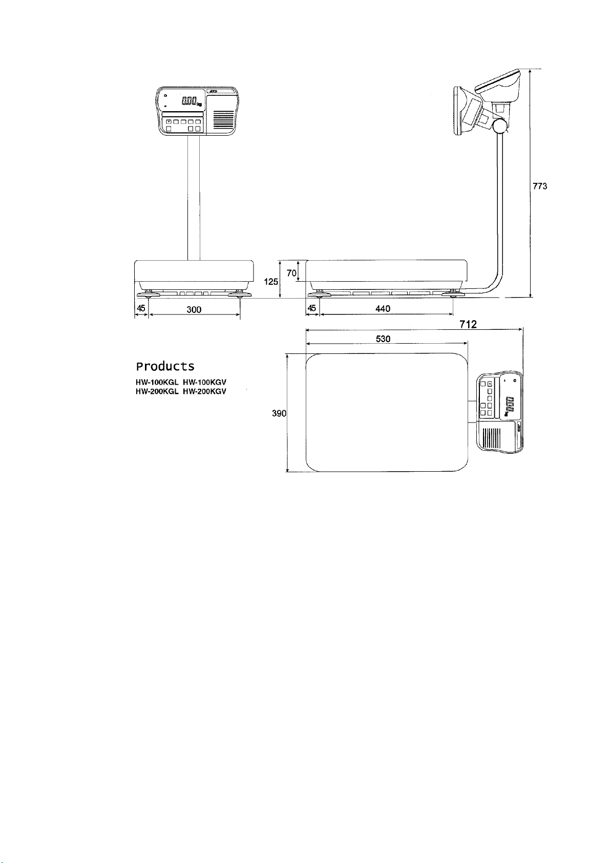
HW-G Instruction Manual Page 67
HW-G OZIM v1a
Page 70

19 Maintenance
Refer to “4. Caution” for use.
Refer to “6.1. Display and Symbols “ and corresponding mode for displayed error
code.
Refer to “14. Calibration (Adjusting Scale)” for precision weighing.
Periodically check the accuracy of weighing. Calibrate the scale, if it is moved to
another location or the environment has changed.
19.1 Repair
Do not disassemble/ assemble the scale without an authorised service engineer.
It may cause an electric shock or damage to the scale, etc. In this case, repair is
not covered under warranty. Contact your local A&D dealer if your scale needs
service or repair.
19.2 Check Points Before Calling Maintenance
In this situation Confirm these items
Is the AC adaptor properly connected?
Nothing displayed. Is the AC adaptor the correct voltage ?
Scale does not turn on. Are the batteries dead ?
Is the battery polarity correct ?
The scale does not display Check around weighing pan for foreign
bodies.
zero at first. Is there anything on the pan?
The weighing value is unstable due to drift,
888888 is displayed and does vibration or other
not proceed Check around weighing panfor foreign
bodies.
Check the connection of load cell cable.
------ is displayed and does Check around weighing pan. Remove
not proceed. anything on the pan.
Make zero point calibration of the scale.
Cal e is displayed Calibration error that means “Too heavy”.
-Cal e is displayed Calibration error that means “Too light”.
e is displayed Weighing error that means “Over load”.
-e is displayed Weighing error that means “Under load”.
Fixed display Do you use the “hold function”.
HW-G OZIM v1a
Turn the scale off then on.
HW-G Instruction Manual Page 68
Page 71

 Loading...