

Page 1
LIMITED ONE YEAR WARRANTY
Chaney Instrument Company warrants that all products it manufactures to be of good material and workmanship and to be free of
defects if properly installed and operated for a period of one year from date of purchase. REMEDY FOR BREACH OF THIS
WARRANTYIS EXPRESSLY LIMITED TO REPAIR OR REPLACEMENT OF DEFECTIVE ITEMS. Any product which, under normal use
and service, is proven to breach the warranty contained herein within ONE YEAR from date of sale will, upon examination by
Chaney, and at its sole option, be repaired or replaced by Chaney. In all cases, transportation costs and charges for returned
goods shall be paid for by the purchaser. Chaney hereby disclaims all responsibility for such transportation costs and charges.
This warranty will not be breached, and Chaney will give no credit for products it manufactures which shall have received normal
wear and tear, been damaged, tampered, abused, improperly installed, damaged in shipping, or repaired or altered by others than
authorized representatives of Chaney.
THE ABOVE-DESCRIBED WARRANTYIS EXPRESSLY IN LIEU OF ALL OTHER WARRANTIES, EXPRESSOR IMPLIED, AND ALL
OTHER WARRANTIES ARE HEREBY EXPRESSLY DISCLAIMED, INCLUDING WITHOUT LIMITATION THE IMPLIED WARRANTY OF
MERCHANTABILITYAND THE IMPLIED WARRANTY OF FITNESS FOR A PARTICULAR PURPOSE. CHANEY EXPRESSLY DISCLAIMS
ALL LIABILITY FOR SPECIAL, CONSEQUENTIAL OR INCIDENTAL DAMAGES, WHETHER ARISING IN TORT OR BY CONTRACT FROM
ANY BREACH OF THIS WARRANTY. SOME STATES DO NOT ALLOW THE EXCLUSION OR LIMITATION OF INCIDENTAL OR
CONSEQUENTIALDAMAGES,SO THE ABOVE LIMITATION OR EXCLUSION MAY NOT APPLY TO YOU. CHANEY FURTHER DISCLAIMS
ALL LIABILITY FROM PERSONAL INJURY RELATING TO ITS PRODUCTS TO THE EXTENT PERMITTED BY LAW. BY ACCEPTANCE
OF ANY OF CHANEY'S EQUIPMENT OR PRODUCTS, THE PURCHASER ASSUMES ALL LIABILITY FOR THE CONSEQUENCES
ARISING FROM THEIR USE OR MISUSE. NO PERSON, FIRM OR CORPORATION IS AUTHORIZED TO ASSUME FOR CHANEY ANY
OTHER LIABILITY IN CONNECTION WITH THE SALE OF ITS PRODUCTS. FURTHERMORE, NO PERSON, FIRM OR CORPORATION IS
AUTHORIZEDTO MODIFY OR WAIVE THE TERMS OF THIS PARAGRAPH, AND THE PRECEDING PARAGRAPH,UNLESS DONE IN
WRITING AND SIGNED BY A DULY AUTHORIZED AGENT OF CHANEY. THIS WARRANTY GIVES YOU SPECIFIC LEGAL RIGHTS, AND
YOU MAY ALSO HAVE OTHER RIGHTS WHICH VARY FROM STATE TO STATE.
For in-warranty repair, please contact:
Customer Care Department
Chaney Instrument Company
965 Wells Street
Lake Geneva, WI 53147
Chaney Customer Care
877-221-1252
Mon-Fri 8:00 a.m. to 4:45 p.m. CST
www.chaneyinstrument.com
INST - 01099 032010
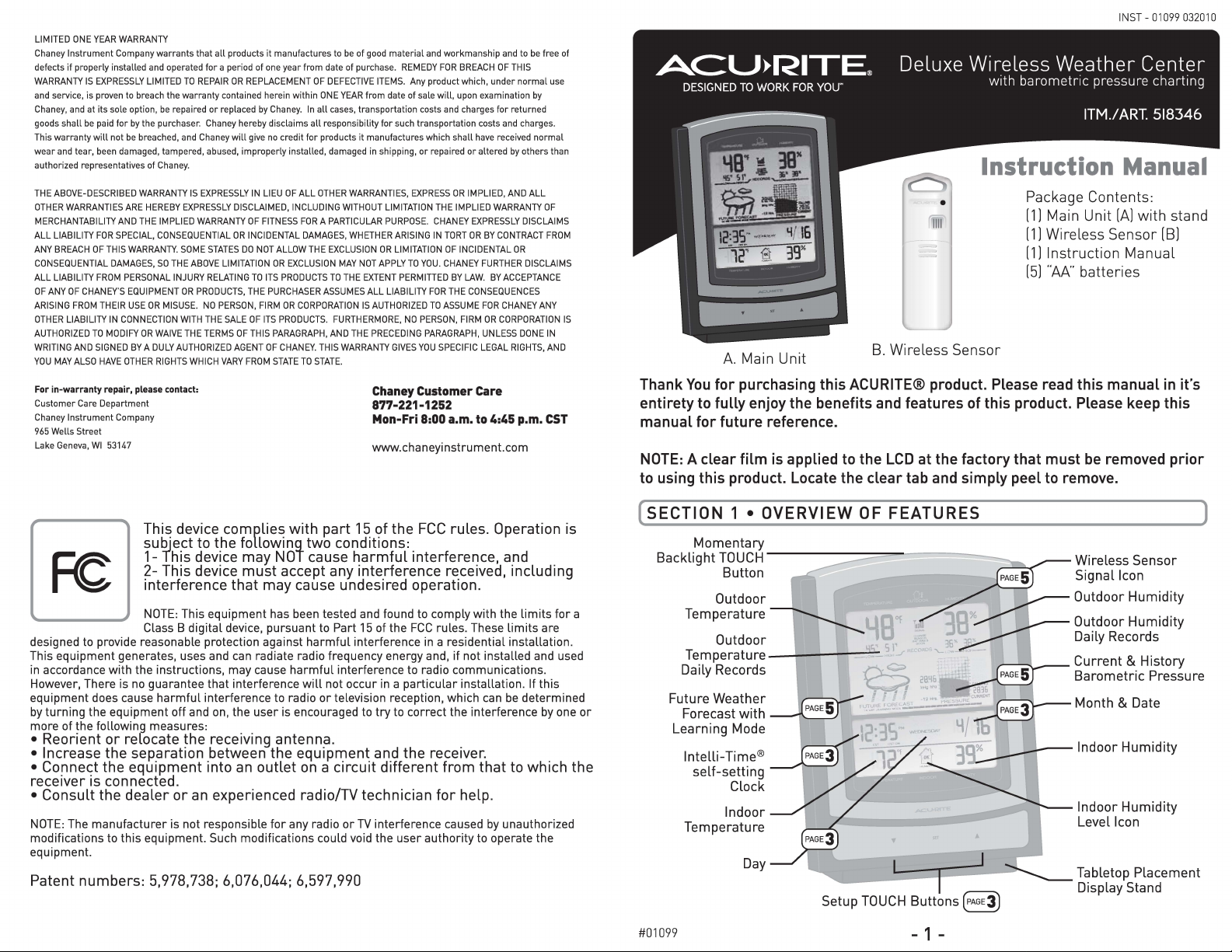
Instruction Manual
Package Contents:
[1l Main Unit [Alwith stand
[1lWireless Sensor [Bl
[1l
Instruction Manual
[5l "AA" batteries
A. Main Unit
Thank You for purchasing this ACURITE® product. Please read this manual in it's
entirety to fully enjoy the benefits and features of this product. Please keep this
manual for future reference.
NOTE: A clear film is applied to the LCD at the factory that must be removed prior
to using this product. Locate the clear tab and simply peel to remove.
B. Wireless Sensor
This device complies with part 15 of the FCC rules. Operation is
subject to the following two conditions:
1- This device may NOT cause harmful interference, and
2- This device must accept any interference received, including
Fe
designed to provide reasonable protection against harmful interference in a residential installation.
This equipment generates, uses and can radiate radio frequency energy and, if not installed and used
in accordance with the instructions, may cause harmful interference to radio communications.
However, There is no guarantee that interference will not occur in a particular installation. If this
equipment does cause harmful interference to radio or television reception, which can be determined
by turning the equipment off and on, the user is encouraged to try to correct the interference by one or
more of the following measures:
interference that may cause undesired operation.
NOTE: This equipment has been tested and found to comply with the limits for a
Class B digital device, pursuant to Part 15 of the FCC rules. These limits are
• Reorient or relocate the receiving antenna.
• Increase the separation between the equipment and the receiver.
• Connect the equipment into an outlet on a circuit different from that to which the
receiver is connected.
• Consult the dealer or an experienced radio/TV technician for help.
NOTE: The manufacturer is not responsible for any radio or TV interference caused by unauthorized
modifications to this equipment. Such modifications could void the user authority to operate the
equipment.
Patent numbers: 5,978,738; 6,076,044; 6,597,990
(SECTION 1 • OVERVIEW OF FEATURES
lntelli-Time®
self-setting
Clock
Indoor
Temperature
Day
J
L I
~AGE3)
#01099
Setup TOUCH Buttons
- 1 -
)
--~- Indoor Humidity
Indoor Humidity
Level Icon
Tabletop Placement
Display Stand
Page 2
[ SECTION 2 • SETUP
Battery Choice & Temperature Range
Extended periods of cold temperatures ( below -4°F / -20°C I can cause alkaline
batteries to function improperly. This will cause the outdoor wireless sensor to
stop transmitting temperature readings. Use lithium batteries in these low
temperature conditions to ensure continued operation for wireless sensors placed
outdoors. NOTE: Rechargeable batteries are not recommended due to higher
operating voltages.
(70°C) 158°F I
ALKALINE
BATTERIES
WARNING: This product contains a button battery. If swallowed, it could cause
severe injury or death in just 2 hours. Seek medical attention immediately
«AIM&(70°C>158°FI
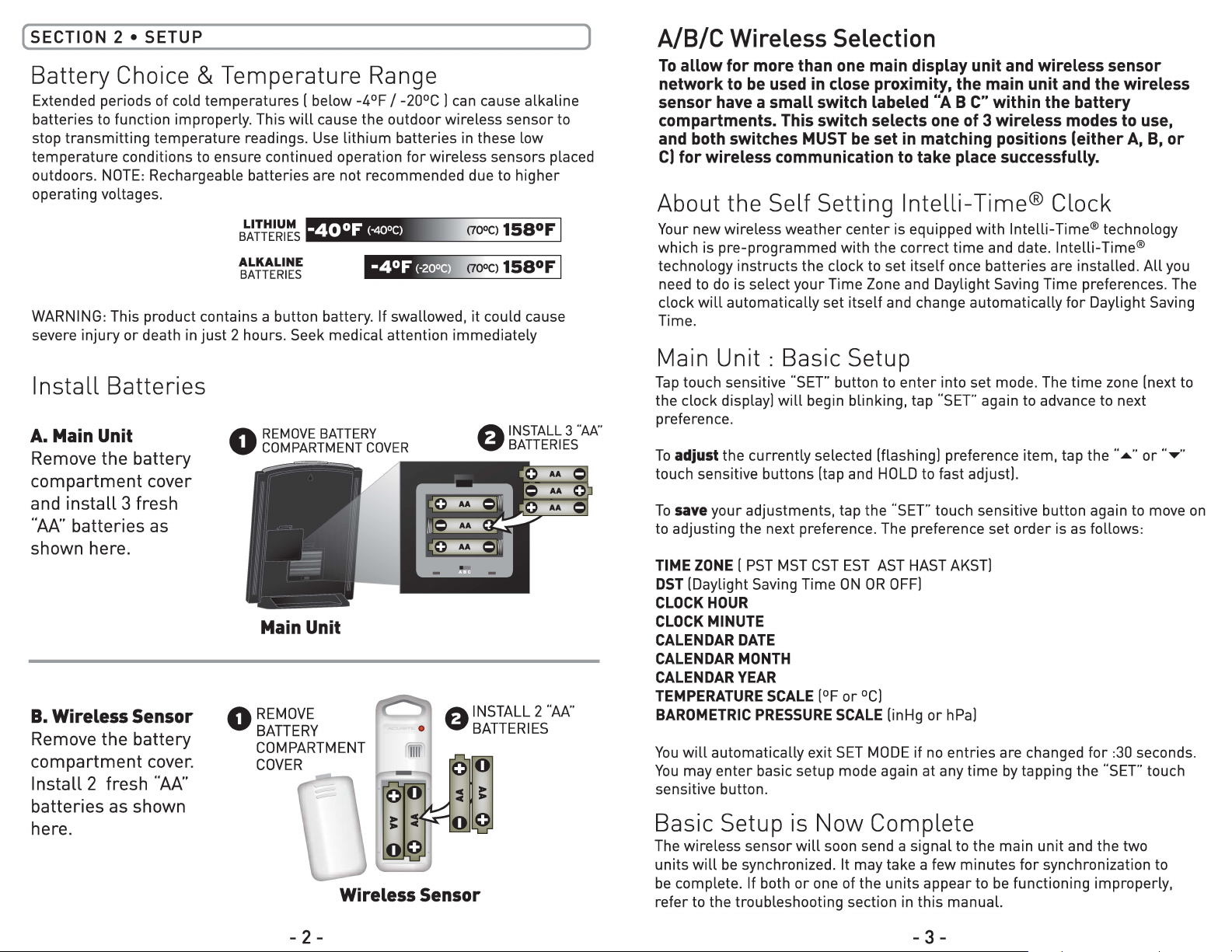
Install Batteries
A. Main Unit
Remove the battery
compartment cover
and install 3 fresh
"AA" batteries as
shown here.
B. Wireless Sensor
Remove the battery
compartment cover.
Install 2 fresh "AA"
batteries as shown
here.
REMOVE BATTERY
0
COMPARTMENT COVER
Main Unit
REMOVE
0
BATTERY
COMPARTMENT
COVER
Wireless Sensor
INSTALL 3 '"AA ..
0
BATTERIES
AA
AA 0
~
)
A/8/C Wireless Selection
To allow for more than one main display unit and wireless sensor
network to be used in close proximity, the main unit and the wireless
sensor have a small switch labeled "A B C" within the battery
compartments. This switch selects one of 3 wireless modes to use,
and both switches MUST be set in matching positions (either A, B, or
CJ for wireless communication to take place successfully.
About the Self Setting lntelli-Time® Clock
Your new wireless weather center is equipped with lntelli-Time® technology
which is pre-programmed with the correct time and date. lntelli-Time®
technology instructs the clock to set itself once batteries are installed. All you
need to do is select your Time Zone and Daylight Saving Time preferences. The
clock will automatically set itself and change automatically for Daylight Saving
Time.
Main Unit : Basic Setup
Tap touch sensitive "SET" button to enter into set mode. The time zone (next to
the clock display) will begin blinking, tap "SET" again to advance to next
preference.
To adjustthe currently selected (flashing) preference item, tap the .. ,,,,. .. or .. .., ..
touch sensitive buttons (tap and HOLD to fast adjust).
To
saveyour adjustments, tap the "SET" touch sensitive button again to move on
to adjusting the next preference. The preference set order is as follows:
TIME ZONE ( PST MST CST EST AST HAST AKST)
DST(Daylight Saving Time ON OR OFF)
CLOCK HOUR
CLOCK MINUTE
CALENDAR DATE
CALENDAR MONTH
CALENDARYEAR
TEMPERATURESCALE
BAROMETRICPRESSURE SCALE (in Hg or hPa)
You will automatically exit SET MODE if no entries are changed for :30 seconds.
You may enter basic setup mode again at any time by tapping the "SET" touch
sensitive button.
(°F or °C)
Basic Setup is Now Complete
The wireless sensor will soon send a signal to the main unit and the two
units will be synchronized. It may take a few minutes for synchronization to
be complete. If both or one of the units appear to be functioning improperly,
refer to the troubleshooting section in this manual.
- 2 -
- 3 -
Page 3

Troubleshooting
Problem Possible Solution
Bad
Wireless Sensor
Reception
Tull
No Wireless Sensor Data
[no communication]
Tull
Display Not Working
PRODUCT REGISTRATION
To receive product updates
www.chaneyinstrument.com
Imported by:
Costco Wholesale Corporation
P.O. Box 34535
Seattle, WA 98124-1535
U.S.A.
1-800-77 4-2678
Shop at www.costco.com
no bars
no bars and flashing
-- .. data
Main Unit
Please DO NOT return product to the retail store.
For technical assistance and product return information, please call
Customer Care:
877-221-1252 Mon. - Fri. 8:00A.M. to 4:45 P.M. [CST)
www.chaneyinstrument.com
and information,
Log on to
Relocate the main unit and/or the wireless
sensor. Both units must be within 330 feet
[100ml from each other. Make sure both units
are placed at least 3 feet [.91 ml from other
electronic appliances and devices that may
interfere with the wireless communication
[such as TVs, microwaves, computers etc).
NOTE: It may take up to 20 minutes for the
main unit to re-synchronize with the sensor
when batteries are replaced. Use lithium
batteries in sensor when temperature is
below -4°F [-20°C).
If wireless reception is bad [no bars). see
"Bad Reception" section above. The wireless
ID setting on each unit must match for all
units to communicate properly. See "Set
Wireless ID" on the next page.
Make certain that the batteries are installed
correctly.
The batteries may need replacing.
r
se rc:hKeyword or m#
1
1
111•lil•
Product Documentation
Frequently Asked Questions
(FAQ)
Troubleshooting
. ,
.:. ...
-
.
V
'd
~
$
CONTACT US•
- 6 -
Set Wireless ID
This wireless thermometer
uses long range 433mhz
radio frequency for
communication.
In the event that you have
reception problems due to
interference, both the main
unit and the wireless sensor
have a selectable wireless
ID. The ID switches are
located within the battery
compartments of the main
unit and the wireless
sensor.
You may choose A, B or C;
but both the main unit and
wireless sensor ID's
the
must match for successful
synchronization.
Both wireless ID's
must match
( SECTION 5 • PRODUCT SPECIFICATIONS
Measurement Ranges - Model# 01099
Temperature
Main Unit: 32°F to 122°F / o
Wireless Sensor: -40°F to 158°F / -40°C to 70°C
0
c to 50°C
Specifications
Power Requirements
Main Unit: 3 x "AA" alkaline or lithium batteries
Wireless Sensor: 2 x
Wireless Communication 433 mhz Radio Frequency-Transmission every 16 seconds
PLEASE DISPOSE OF OLD OR DEFECTIVE BATTERIES IN AN ENVIRONMENTALLY
SAFE WAY AND IN ACCORDANCE WITH YOUR LOCAL LAWS AND REGULATIONS .
BATTERY SAFETY:
installation. Remove batteries from equipment which is not to be used for an extended
period of time. Follow the polarity(+/-) diagram in the battery compartment. Promptly
remove dead batteries from the device. Dispose of used batteries properly. Only batteries of
the same or equivalent type as recommended are to be used. DO NOT incinerate used
batteries. DO NOT dispose of batteries in fire, as batteries may explode or leak. DO NOT mix
old and new batteries or types of batteries (alkaline/standard). DO NOT use rechargeable
batteries. DO NOT recharge non-rechargeable batteries. DO NOT short-circuit the supply
terminals.
"M' alkaline or lithium batteries
Clean the battery contacts and also those of the device prior to battery
- 7 -
]
Page 4

(SECTION 3 • PLACEMENT
)
( SECTION 4 • OPERATION
)
Now that setup is complete, you must choose a location to place the wireless
sensor and the main unit. The wireless sensor MUST be placed less than 330 feet
(100 meters] away from the main unit.
This wireless thermometer uses radio frequency for communication, which is
susceptible to interference from other electronic devices and large metallic items
or thick walls. Always place both units at least 3 feet (.91 ml away from
appliances
wireless communication
ITV, microwave, radios, etc. I or objects that may interfere with the
I large metal surfaces, thick stone walls, etc. ].
--'01'.,.
- -
; I \'
(330 feet maximum]
[100 meters]
Placement of Main Unit
Place the main unit in a dry area free of dirt and dust. To help ensure
I
an accurate indoor temperature measurement, be sure to place the
main unit out of direct sunlight, and away from any heat sources or
vents in your home. There are 2 placement options for the main unit.
You may hang the main unit on a wall using the integrated hang hole.
Alternatively, you may place the main unit on a table top or other flat
surface using the included detachable table top display stand.
Placement of Sensor
The wireless sensor MUST BE PLACED OUTDOORS to observe outdoor
temperatures. The wireless sensor must be placed less than 330 feet
(100 ml from the main unit. The wireless sensor is water
is designed for general outdoor use. However, to extend the life of the
product, place the wireless sensor in an area protected from direct
weather elements.
•
measurement, be sure the wireless sensor is placed out of direct
sunlight and away from any heat sources.
There are 2 placement options for the wireless sensor. You may hang it
using one of the two integrated hang holes, or use string (not included)
to hang it from a suitable location like a well covered tree branch.
Toensure an accurate outdoor temperature
resistantand
After the main unit and the wireless sensor are both powered on and wireless
synchronized, no further input is required. This section outlines some of the
main features of this weather station.
014 Day Learning Mode
This weather station has a patented
"fourteen day learning mode" calibration
process. During this learning mode the
weather station will make altitude
calculations that may affect the accuracy
of the forecast. Once the 14 day learning
mode process is complete, the learning
mode icon will disappear and the weather
forecast should be ready for superior
operation.
0 Forecast Icon
This feature gives you the predicted
weather forecast for the next 12 to 24
hours based on an advanced algorithm
that includes barometric pressure and
temperature. This weather station will
provide the most accurate forecast that a
single station weather instrument can
provide.
C9Barometric Pressure: Current and History
This weather station has a pressure graph
that tracks and displays the barometric
pressure 12 hours ago as well as the current
barometric pressure. Additionally, the graph 28.lf6-
will automatically display the "FALLING",
"STEADY" or "RISING" icon and a curve to
represent the rate of change over the
previous 12 hour time period.
lnHg
-12 Hrs.
PRESSURE CURRENT
0 Wireless Signal Reception Icons T.111
The main unit has a signal reception icon near the outdoor temperature
display area. If there are a low number of "bars" present, you may
experience no temperature display
may need to relocate one or both of the units. If most or all 4 of the bars are
present, wireless reception is good and no action is required.
I"--"] or inaccuracy. In either case, you
- FALLING
: 28.36
- 4 -
- 5 -
 Loading...