

Page 1
100S READOUTS
FOR TURNING APPLICATIONS
REFERENCE MANUAL
Page 2

100S Turning Reference Manual
i
TABLE OF CONTENTS
Overview. . . . . . . . . . . . . . . . . . . . . . . . . . . . . . . . . . . . . . . . . . . . . . 1
Preparation . . . . . . . . . . . . . . . . . . . . . . . . . . . . . . . . . . . . . . . . . . . . 2
Packing List . . . . . . . . . . . . . . . . . . . . . . . . . . . . . . . . . . . . . . . . 2
Warranty Records. . . . . . . . . . . . . . . . . . . . . . . . . . . . . . . . . . . . 2
Installing the Scales . . . . . . . . . . . . . . . . . . . . . . . . . . . . . . . . . . . . . 3
Installing the Readout. . . . . . . . . . . . . . . . . . . . . . . . . . . . . . . . . . . . 3
Power Up . . . . . . . . . . . . . . . . . . . . . . . . . . . . . . . . . . . . . . . . . . . . . 3
Display Saver . . . . . . . . . . . . . . . . . . . . . . . . . . . . . . . . . . . . . . . . . . 3
General
Setup
Operation
Parameter Setup 4
Display Resolution. . . . . . . . . . . . . . . . . . . . . . . . . . . . . . . . . . . . . . 5
Linear Error Compensation . . . . . . . . . . . . . . . . . . . . . . . . . . . . . . . 6
How to Determine the Linear Error Compensation . . . . . . . . . . . . . 7
Count Direction. . . . . . . . . . . . . . . . . . . . . . . . . . . . . . . . . . . . . . . . . 8
Scale Resolution . . . . . . . . . . . . . . . . . . . . . . . . . . . . . . . . . . . . . . . . 9
Input 3 On/Off . . . . . . . . . . . . . . . . . . . . . . . . . . . . . . . . . . . . . . . . . 9
Position Recall . . . . . . . . . . . . . . . . . . . . . . . . . . . . . . . . . . . . . . . . . 9
Testing the Scales . . . . . . . . . . . . . . . . . . . . . . . . . . . . . . . . . . . . . . . 10
Radius and Diameter. . . . . . . . . . . . . . . . . . . . . . . . . . . . . . . . . . . . . 12
Setting the Datum (Absolute Zero) . . . . . . . . . . . . . . . . . . . . . . . . . 13
Example: Setting Up Your Job . . . . . . . . . . . . . . . . . . . . . . . . . 15
Incremental Dimensions . . . . . . . . . . . . . . . . . . . . . . . . . . . . . . . . . . 16
Example: Incremental Dimensions . . . . . . . . . . . . . . . . . . . . . . 17
Tool Offset . . . . . . . . . . . . . . . . . . . . . . . . . . . . . . . . . . . . . . . . . . . . 19
532822-20
Page 3

100S Turning Reference Manual
ii
TABLE OF CONTENTS
Troubleshooting
Reference
Troubleshooting Introduction . . . . . . . . . . . . . . . . . . . . . . . . . . . . . . 21
Error Messages (General). . . . . . . . . . . . . . . . . . . . . . . . . . . . . . . . . 26
(Keypad Test) . . . . . . . . . . . . . . . . . . . . . . . . . . . . . 27
Electrical Specifications . . . . . . . . . . . . . . . . . . . . . . . . . . . . . . . . . . 28
Factory Default Settings . . . . . . . . . . . . . . . . . . . . . . . . . . . . . . . . . . 29
Keypad . . . . . . . . . . . . . . . . . . . . . . . . . . . . . . . . . . . . . . . . . . . . . . . 30
Conventions . . . . . . . . . . . . . . . . . . . . . . . . . . . . . . . . . . . . . . . . . . . 32
Count Direction . . . . . . . . . . . . . . . . . . . . . . . . . . . . . . . . . . 32
Page 4
100S Turning Reference Manual
1
GENERAL
Overview
This manual will guide you through the installation, setup, and operation
of the 100S system. Use it to get your system up and running “out of the
box” and as a quick reference guide for your day-to-day operations.
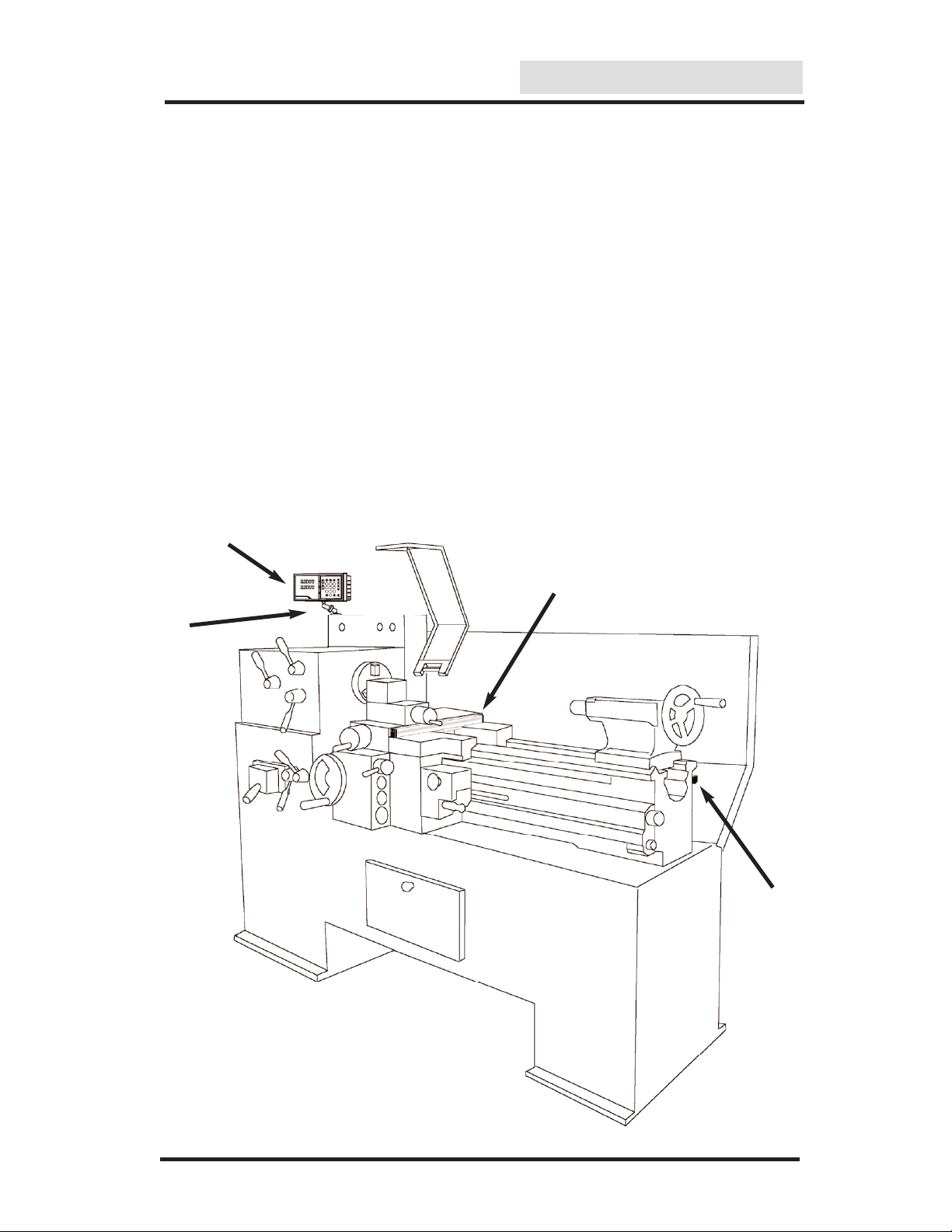
Here’s how a typical machine will look after the installation is complete:
100S Readout
Mounting
Arm
X-axis Scale
Z-axis Scale
Page 5

100S Turning Reference Manual
2
Packing List
• Readout instructions
• Installation instructions
• Mounting arm
•
ENC 125 scales
- Cable mounting hardware
- Scale mounting hardware
• Warranty card
If a component is missing, contact your
100S distributor
immediately for replacement.
Verify that you have received all of the components for your system:
Warranty Records
Complete the warranty card included with your 100S system.
The readout’s catalog and serial numbers are on the back of the display;
the scale’s catalog number is on the scale assembly label; and the serial
number is on the scale case.
Copy the information here for your own records and mail the warranty
card as soon as possible.
Distributor: _____________________________________________
Address: _____________________________________________
Telephone: _____________________________________________
Catalog No. Serial No.
Readout ________________ ___________________
Axis #1: ________________ ___________________
Axis #2: ________________ ___________________
Axis #3: ________________ ___________________
Date of Purchase: ____________________________________
Preparation
GENERAL
Page 6

100S Turning Reference Manual
GENERAL
Installing the Readout
Follow the readout installation instructions that are included with your
mounting arm bracket kit. The electrical specifications for the readout
are listed on pg. 28.
Installing the Scales
Please see the manual included with the scale for installation instructions.
3
Power Up
Press the switch on the back of the readout to power up the system. A
series of tests will check that the display, keypad, and memory are all
working properly.
If a problem is detected, an error code will appear on the screen. (Error
messages and solutions are listed on pgs. 26 - 27.) It is important to
note that the E1 message will appear every time you power up your
system and does not indicate a problem. It merely indicates that the
system had lost power. To acknowledge the message, press the CLEAR
key and proceed to the DRO mode.
Note:
If the E1 message appears at any other time during normal
operation, refer to pg. 26 for possible problems and solutions.
When the system is not used for more than 90 minutes, a decimal point
will “scroll” across the X-axis display, indicating that the display saver
has been activated. The display saver, like a screen saver on a computer
monitor, will help prolong the life of your readout.
If the display saver has been activated, press any key on the readout or
move any axis to return to the normal DRO view.
Display Saver
Page 7

4
100S Turning Reference Manual
SETUP
There are five to six parameters that you can define on your system:
• Display resolution (diS)
• Linear error compensation (LEC)
• Scale resolution (rES)
• Scale count directions (Ct dir)
• Input 3 ON/OFF (InPUt 3) 2+ units only
• Position Recall (recall)
Establish each setting the first time you power up the system. You can
change the parameters later by returning to Setup and then using the
ENTER key to scroll to the appropriate category.
Anytime you change the linear error compensation, or count direction
for an axis, the absolute and incremental displays for that axis will be
reset to 0. If you change these settings, you’ll need to reestablish the
datum point.
When in the Setup mode, use the CLEAR key when you want to backspace, restore the previous value or access the previous parameter.
Parameter Setup
Page 8
5
100S Turning Reference Manual
SETUP
The display resolution determines how detailed each scale’s position
will be displayed on the readout. Use the setting that best suits each job.
Display Resolution
To change the display resolution:
• Press the SETUP key. (“diS” will show on the display.)
• Press the
X or Z key for the display you want to change.
For 10µm scales, the display resolution will toggle between 0.01 mm
(0.0005”) and 0.02 mm (0.001”). For 5µm scales, it will toggle
between 0.005 mm (0.0002”) and 0.01 mm (0.0005”). For 1µm scales,
it will toggle between 0.001 mm (0.00005”) and 0.002 mm (0.0001”).
• After you complete setting your display resolution, press ENTER to
continue with setup or press ENTER then SETUP to return to the normal DRO display.
Page 9
6
100S Turning Reference Manual
SETUP
Linear Error Compensation
With 100S, you can compensate for machine tool wear. If you know the
linear error compensation (LEC) value in parts-per-million (PPM), you
can enter it directly.
If you don’t know the LEC, use the formula on the next page to determine
the value for each axis.
• Move to the “Linear Error Compensation” display in the Setup
mode. (Press SETUP and then the ENTER key until “LEC”
appears).
• Press the
X or Z key for the axis you want to change.
100S will display the current LEC value for that axis.
• Using the keypad, enter the linear error compensation factor
(in PPM), followed by the ± key for negative values. The number
must be within -9999 and 9999 (use whole numbers). The formula for
calculating the value is on the next page.
• After you complete setting your LEC, press ENTER to continue with
setup or press ENTER then SETUP to return to the normal DRO
display.
To change the linear error compensation:
Page 10

100S Turning Reference Manual
7
SETUP
(
S - M
M
LEC =
)
x 1,000,000
S = Standard length
M = Measured length
• In the DRO mode.
• Place a standard of known length on the machine. Make sure it’s
parallel with the axis being measured.
• Put the readout in the absolute display mode (
ABS/INCR key).
• Using an indicator, locate one end of the standard.
• Press the
ZERO key twice for the axis you are measuring.
“0” should appear on the display.
• Move the indicator along the axis until it reaches the opposite
end of the standard.
• Write down the length that is shown on the readout display for
that axis.
• Use the formula below to calculate the LEC for the axis you just
measured. Enter the result in the LEC parameter (previous page).
How to Determine the Linear Error Compensation
Follow this procedure for each axis:
Formula
Example
If the length of the
standard you used is
10” and the measured
length is 9.995”, then
the LEC for that axis
is 500 parts-per-million (PPM).
(
10 - 9.995
9.995
LEC =
)
x 1,000,000
LEC =
500 PPM
(rounded to the nearest
whole number)
Note
: If the measured length is greater than the standard length the
LEC value will be negative.
Page 11
8
100S Turning Reference Manual
SETUP
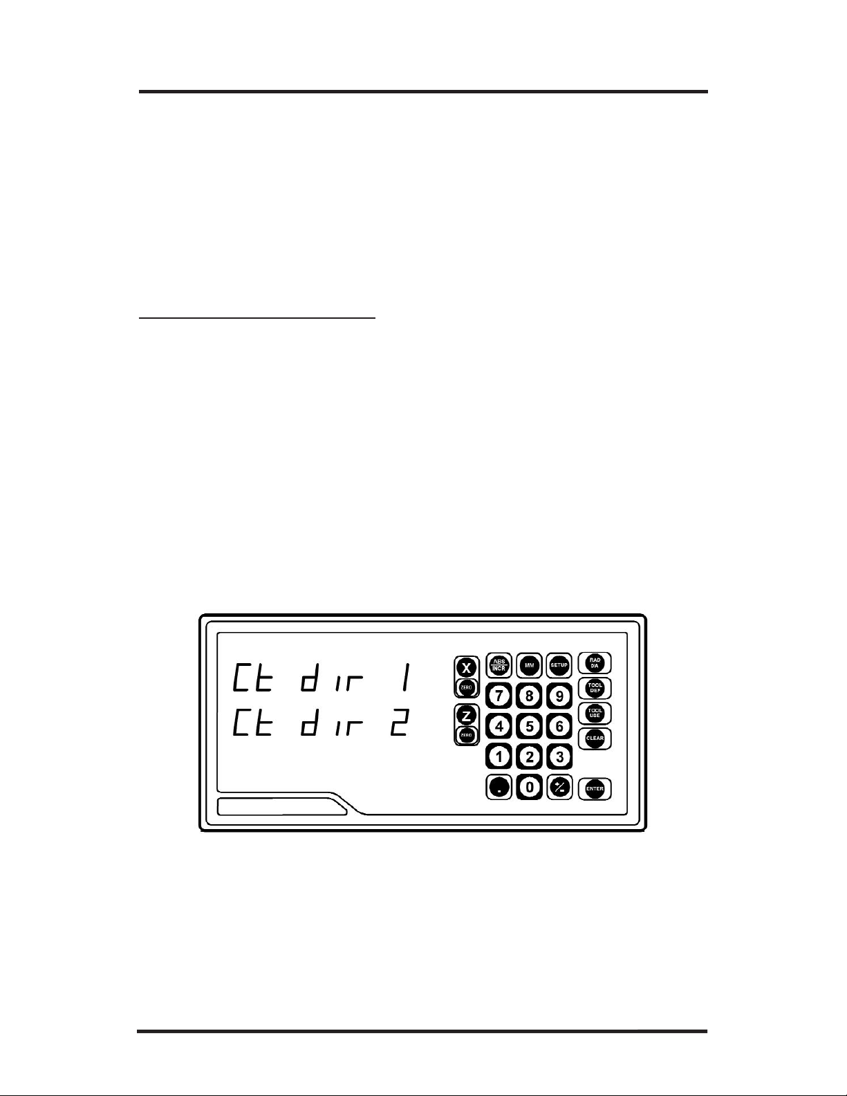
• Move to the “Count Direction” display in the Setup mode. (Press
SETUP and then the ENTER key until “Ct dir” appears).
• Press the appropriate axis key (
X or Z). The current count direction
(1 or 2) will appear.
• After you complete setting your count direction, press ENTER to continue with setup or press ENTER then SETUP to return to the normal
DRO display.
To change the count direction:
Count Direction
Use the count direction setting to define the positive counting direction
for each scale. The direction will be displayed as a “1” or a “2” (the
numbers are not assigned to a particular direction). You only need to
change the count direction if the scale is counting in the negative
direction during a positive move, or vice versa.
Refer to Conventions on pg. 32 for more guidelines.
Page 12

100S Turning Reference Manual
9
SETUP
Scale Resolution
To ensure accurate readings, the scale resolution shown for each axis must
correspond with the resolution of the scales on your machine.
T
o change the scale resolution:
• If necessary, choose “Scale Resolution” from the Setup menu.
(Press SETUP and then the ENTER key until the screen appears).
• Press the appropriate axis key (X, Y or Z) until the appropriate resolution appears. Choose 0.01 mm for 10µm (0.0005”) scales, 0.005 mm
for 5µm (0.0002”) and 0.001 mm for 1µm (0.00005”)scales.
• Repeat the procedure for each axis.
• Press
ENTER to continue with Setup.
Input 3 On/Off (2+ units only)
This parameter allows you to activate the third input. When this input
is enabled, Inputs 2 and 3 will be coupled on the Z-axis (both scales
will count on the Z-axis). The Input 3 scale must have the same scale
resolution as the Input 2 scale.
When Input 3 is enabled, additional parameters will need to be setup.
Refer to the procedures on pages 6-8 for setting up the Linear Error
Compensation and Count Direction Setup functions.
Position Recall
• Set this parameter to the ON position to store the last position
of each axis when power is turned off.
Page 13

100S Turning Reference Manual
SETUP
10
Testing the Scales
Follow these steps to confirm that the scale has been installed properly.
The Counting Test will confirm the scale’s electrical operation, and the
Repeatability Test will check the installation integrity.
Counting Test
• Move the table along each axis, one at a time. Check that the
readout correctly displays the table’s movement. If it doesn’t,
then the scale resolution you selected may not be accurate. Refer
to Scale Resolution, pg. 9.
Repeatability Test
• Locate a magnetic base and dial indicator on the end of the scale.
Zero the readout and the indicator.
• Move the axis through the full travel and return the dial to “0.”
The readout should also read 0 (±0.0005” for 10µm scales;
±0.0002” for 5µm scales; ±0.00005” for 1µm scales). If it
doesn’t, then the scale cable may be loose, or the scale, mounting
bracket, or reading head may need to be tightened or realigned.
• Repeat these steps for each scale.
Page 14

100S Turning Reference Manual
OPERATION
11
Reference Mark Evaluation
ENC 125 encoders contain internal reference marks, approximately 4"
apart along the length of the encoder. These marks enable you to easily
re-locate your correct position after a power interruption. You relocate
your position, relative to the last established datums, by traversing across
one reference mark on each encoder. You must find a convenient reference mark on each encoder prior to establishing your datums, and then
use those same marks during the evaluation procedure, after a power
interruption, to re-establish your position relative to your datums.
To perform Reference Mark Evaluation:
• Move near the appropriate reference mark.
• Press and hold the
DECIMAL key until the decimal points on the
displays start to flash
• Move slowly past the reference mark until the readout recalls its
position.
• Repeat for each axis.
Power On Position Recovery
With the 100S there are two means of position recovery, Position Recall
and Reference Mark Evaluation.
Position Recall
When this feature is active (see setup parameters) the last displayed position is stored in memory when power is lost or turned off. When power is
restored, the stored position is recalled and displayed.
Note:
Any movement that occurs while power is off will be lost.
Whenever power has been off it is recommended that you reestablish workpiece datums using the Reference Mark
Evaluation procedure below).
Page 15

12
100S Turning Reference Manual
OPERATION
Radius and Diameter
Pressing the RAD/DIA key lets you view the X-axis dimension either as
a radius or as a diameter.
Display resolution is affected by the RAD/DIA key.
Page 16

13
100S Turning Reference Manual
OPERATION
Setting the Datum (Absolute Zero)
100S allows you to measure both absolute and incremental dimensions.
A dimension measured from the point you define as the datum is an
absolute dimension. A dimension measured from any other point on
your print is an incremental dimension.
Datum, also known as absolute zero or workpiece zero, is the reference
point from which
100S will base all of your part’s coordinates. When
the readout is in the ABS mode, it is actually measuring the distance
from the datum to the machine axis’ current position.
You will need to establish a datum for every job. Your datum may
already be identified on your print; if it isn’t, then establish a datum that
allows you to measure most of your part’s dimensions directly, with the
least number of calculations.
All of the dimensions in the drawing below are based from the datum.
Page 17

100S Turning Reference Manual
OPERATION
14
• Using the ABS/INCR key, select the absolute (ABS) mode. Also
check that the proper measurement (inch or mm) is selected.
• Using RAD/DIA key, select the Radius mode.
• Move the tool to a known point, i.e. the outside diameter of the
workpiece or the face of the workpiece.
• Press the ZERO key once for the axis (X or Z) for which you are
entering a dimension.
• Using the keypad, enter the distance from your tool’s current
location to the point you want to establish as the datum. Include a
decimal point (.) and minus (-) sign when necessary.
• Press the ZERO key for the other axis, or press ENTER to return
to the DRO display.
To set the datum using an offset:
To set the datum at the tool’s current position:
• Position the workpiece in the chuck. Move the tool until
it is positioned at the location where you would like to establish the
datum.
• Using the ABS/INCR key, select the absolute (ABS) mode.
• Press the X-axis
ZERO key twice to establish the current X-axis
position as the datum. Repeat for the Z-axis.
Page 18

15
100S Turning Reference Manual
OPERATION
1. Place your workpiece into the
chuck.
2. Make a face cut and clear the work
piece by backing the tool off in the
X-axis only. Do not move the Zaxis. (Fig. 1)
3. Zero the Z-axis by pressing the Zzero key twice. (Fig. 2)
4. Make a skim cut on the diameter of
the workpiece and clear the workpiece by backing the tool away in
the Z-axis. Do not move the Xaxis. (Fig. 3)
5. Measure the diameter of the workpiece. (Fig. 4)
6. Press the X-axis zero key once,
then using the keypad, press the
RAD/DIA key to select diameter
and enter the diameter of the
workpiece, then press
ENTER. (Fig. 5)
Example:
Setting Up Your Job
1
2
3
4
5
Page 19

16
100S Turning Reference Manual
OPERATION
As we described earlier, incremental dimensions are measured from the
current tool position. If your tool is currently at 2” and you want to
move an additional 3.125”, you would select the incremental mode,
zero out the axis, and move the axis until the display reads 3.125.
An example of how to measure using incremental dimensions is shown
on the next page.
• Move the machine axis to the point from where you want to
measure an incremental distance.
• Use the ABS/INCR key to select the incremental (INCR) mode on
the readout. Also check that the proper measurement (inch or mm)
is selected.
• Press the
ZERO key below the axis(es) from which you are measur-
ing.
• Move the machine axis.
100S will display the machine
axis’ position in relation to the incremental “0” point(s) for the
axis(es) you chose.
After you have reached the position you want and have machined the
part, you can “zero” each axis again and then measure from that location to the next point on your workpiece or press ABS/INCR to return
to the absolute mode.
To use an incremental dimension
:
Incremental Dimensions
Page 20

100S Turning Reference Manual
OPERATION
17
Example: Incremental Dimensions
Let’s say that your print looks like this:
1. Ensure you are in RAD mode (DIA LED
will be off).
2. Move the tool until the readout display
shows that the X-axis = 1.0000” and
the Z-axis = 2.0000” in the absolute mode.
3. Press the ABS/INCR key to switch to the
incremental mode.
4. Press the X-axis ZERO and the Z-axis
ZERO keys.
5. Begin cutting until the X-axis reads -0.1200”.
Using Incremental Zero
In order to cut a groove to a depth
of 0.120” from the 1” radius, it is
necessary to establish a zero at 1”.
This can be done using the incremental mode without changing the
Datum. Follow these steps:
Using Incremental Dimension Presets
In addition to setting incremental zero at the current
tool position, you can also preset the incremental
zero from the current tool position. Enter the distance and direction you wish to move in relation to
your current position. Follow these steps:
1. Ensure the DIA LED is off
2. Move the tool until the readout display shows that the
X-axis = 1.000” and the Z-axis = 2.0000” in the absolute mode.
3. Press the ABS/INCR to switch to the incremental mode.
4. Press the X key ensure the INCR LED is lit and press the following
key sequence: - . 1 2 ENTER.
5. The X-axis display will show 0.1200”.
6. Begin cutting until the X-axis reads 0.0000”.
Page 21

OPERATION
100S Turning Reference Manual
18
Using Absolute Dimension Presets
You can also preset an absolute dimension from the current tool
position. Enter the distance and direction you wish to move in relation to your current position. Follow these steps:
1. Move the tool away from the workpiece.
2. Press the ABS/INCR to switch to the incremental mode and
ensure the diameter LED is on.
3. Press the X key, ensure the ABS LED is lit and press the follow-
ing key sequence: 1.760, ENTER.
4. Press Z key, ensure the ABS LED is lit and press the following key sequence: 2.0, ENTER.
5. To begin cutting, move Z to 0, then move X to 0.
Page 22

100S Turning Reference Manual
OPERATION
19
The 100S can store the dimensional offset of an additional tool. This
allows you to use two tools without having to reestablish zero as you
change between them. In order for this feature to work, the tools must be
able to repeat their location when they are changed (Repeatable tooling).
To use this feature you must first select the tool number (either 0 or 1).
Tool Offset
1. Place your first tool in the tool holder.
2. Press the TOOL USE key.
3. Press 0 to select the first tool, then press ENTER.
4. Set the Datum (Absolute Zero) for all axes using this tool. See
page 13.
5. Change the tool to the second tool you will be using.
6. Press TOOL USE and enter the number 1 for the second tool.
7. Touch this tool to a diameter of known size.
8. Press the TOOL DEF key and press the X key.
9. Press the RAD/DIA key to select diameter if not already selected.
10. Enter the known diameter. Press ENTER.
Page 23

100S Turning Reference Manual
OPERATION
20
11. Move the tool so that it touches a face of known length.
12. Press the TOOL DEF key and press the Z key.
13. Enter 0 if the tool is at Datum or enter the distance the tool is
from Datum by using the ± key if the tool is in the negative
direction. Press ENTER.
Note: Both tools are now set. To switch between them, change
the tool on your lathe, then press the TOOL USE key,
and select the appropriate tool number.
Page 24

100S Turning Reference Manual
TROUBLESHOOTING
21
Troubleshooting Introduction
Refer to this troubleshooting guide whenever you have questions or
concerns about the operation of your
100S system.
This guide is arranged in three columns entitled Symptom, Probable
Cause and Recommended Corrective Action. The symptoms are listed
in the order of the most common, easiest to check, and least expensive
to correct.
First locate the symptom that best describes the problem you are trying
to solve. Then identify the probable cause that most closely matches the
problem and implement the recommended corrective action.
If a problem persists or cannot be resolved using this manual, contact
your
100S distributor for further assistance.
Page 25

100S Turning Reference Manual
TROUBLESHOOTING
22
Recommended
Corrective Action
Decimal point
scrolls across
display
Press any key or move the
cross slide to return to the
previous screen.
System has been idle
for approximately 90
minutes and is in
“display saver”mode
Symptom
Probable Cause
Screen is
blank
Check that the power
switch on the back of the
console is “on.”
No power to the
readout
Check that the readout’s
power cord is properly
connected to the power
supply.
Check that the power
source meets the specifications required by your
system (pg. 28).
Contact your
100S distrib-
utor for repair/
replacement procedures.
LED failure
Dashes
appear on
screen
The value entered exceeds
the display’s 8-character
capability. Enter a value
with less than 8
characters.
(cont’d next page)
Display overflow
Check the fuse. (Located
below the power switch).
Page 26

100S Turning Reference Manual
TROUBLESHOOTING
23
Keys not
working
properly
Error
messages (E2E56) appear
Causes vary
Invalid key press
Symptom
Recommended
Corrective Action
Probable Cause
Turn the system “off” and
then “on” again, using the
switch on the back of the
readout.
If an error (besides E1) is
still detected when the
system is powered up,
contact your 100S distributor for repair/replacement
procedures. Refer to pgs.
26 - 27 for a list of error
messages.
Dashes
appear on
screen
(cont’d)
Move the axis toward
the “0” position. As the
scale counts down, the
display will show the
correct position.
Display overflow
Turn the system “off” and
then “on” again, using the
switch on the back of the
readout. If an error (besides
E1) is detected when the
system is powered up, contact your 100S
distributor for
repair/replacement
procedures. Refer to pg. 2627 for a list of error messages.
Error
message (E1)
appears
Power loss occurred
This is a normal message at power up. If the
message appears at any
other time during operation, a problem may
have occurred. Refer to
pg. 26 for details.
Page 27

100S Turning Reference Manual
TROUBLESHOOTING
24
Scale counts,
but not
correctly
Check that the scale cable
is securely connected to
the readout.
Loose cable
Check that the scale cable
is connected to the correct
input on the back of the
readout.
Wrong input
Check the scale and reading head for proper installation (refer to scale installation instructions).
Scale not installed
properly
Scale won’t
count
Check the scale and reading head for proper installation (refer to scale installation instructions). Clean
the scale, if necessary.
Scale not installed
properly
Change the count direction
(pg. 8).
Wrong count
direction
Symptom
Recommended
Corrective Action
Probable Cause
Unplug the scale from the
readout and plug it into an
input for another axis.
If the scale still does not
count, the reading head
may need to be replaced. If
the scale counts on the
other axis then the display
may need to be replaced.
See LED Failure.
The scale’s reading
head is not working
properly
Page 28

100S Turning Reference Manual
TROUBLESHOOTING
25
Improper procedure
Press the
ENTER key after
each parameter value is
entered. If you press
another key instead, the
new value may not be
saved. Refer to pgs. 4 - 10
for proper procedures.
Setup does
not save
values
Numbers
don’t
appear/are
faded on the
display
LED failure
Turn the system “off” and
then “on” again, using the
switch on the back of the
readout. If this does not
correct the problem,
contact your
100S distrib-
utor for repair/replacement
procedures.
Symptom
Recommended
Corrective Action
Probable Cause
Page 29

100S Turning Reference Manual
26
TROUBLESHOOTING
A ROM memory error has occurred. Press the CLEAR
key to acknowledge the error. If the system does not
operate properly, contact your
100S distributor for
repair/replacement procedures.
A power loss has occurred. This message will appear
every time you power up the system and can be cleared
by pressing the
CLEAR key. If the E1 message appears
at any time other than at power up, a power interruption
has occurred and your current position may be lost. Reestablish the datum if necessary. If the problem persists,
contact your distributor for repair/replacement procedures.
A random access memory (RAM) error has occurred.
Press the
CLEAR key to acknowledge the error. If the
system does not operate properly, contact your
100S
distributor for repair/replacement procedures.
A scale miscount error (invalid waveform) has occurred.
The E9 message will appear on the axis that has the
error. Press
CLEAR to reset the axis(es). Your current
position may be lost. Re-establish the datum if necessary.
If the system does not operate properly, contact your
100S distributor for repair/replacement procedures.
Error Messages (General)
E1
E2
E3
E4
E9
When 100S is powered up, it will run a series of tests to ensure that the
software is working properly. If an error message appears, refer to the
charts below for a diagnosis and solution.
An EEPROM memory error has occurred. Press the
CLEAR key to acknowledge the error. The datum and
setup information may be lost. These areas should be
checked and reestablished upon power up. If the problem
persists, contact your distributor for repair/replacement
procedures.
Page 30

100S Turning Reference Manual
27
TROUBLESHOOTING
SETUP key
E11
E12
MM key
E15
E16
X key
E18
E21
TOOL DEF key
E22
E25
7 key
E26
E28
RAD/DIA key
ABS/INCR key
9 key
8 key
ZERO key for
the X-axis
E31
6 key
E35
E36
E38
E41
E45
E46
E48
E51
E54
E55
E32
E56
TOOL USE key
5 key
4 key
Z key
E33
CLEAR key
3 key
2 key
1 key
ZERO key for
the Z-axis
± key
ENTER key
0 key
Decimal point
(.) key
Error Messages (Keypad Test)
The messages below indicate that a problem was found during the keypad test at startup. If an error message appears, turn the system off,
press the appropriate key to release it back into position, and then
restart the system. (Or you can press the
CLEAR key to clear the error
message.) If the key does not work during normal operation, contact
your distributor for repair/replacement procedures.
Page 31

28
100S Turning Reference Manual
REFERENCE
Characteristic
Specification
Operating conditions
0° to 40°C (32° to 104°F)
25% to 85% relative humidity
(non-condensing)
Storage conditions
-40° to 60°C (-40° to 140°F)
25% to 85% relative humidity
(non-condensing)
100 - 240 V~
50 - 60Hz
25 VA max
Input requirements:
Voltage
Frequency
Current
Fuse
500mA, slo-blo
Position signals: channels A & B
TTL square wave signal in quadrature
(90° nominal phase relationship)
Maximum input rate: 70 kHz
Encoder input
This device complies with Part 15 of the FCC
Rules. Operation is subject to the following
two conditions: (1) this device may not cause
harmful interference, and (2) this device must
accept any interference received, including
interference that may cause undesired operation.
Size
9.875” x 4.679” x 4.75”
Electrical Specifications
Weight
4 lbs., 2 oz.
Mounting
Bottom; two 1/4”-20 threaded inserts
Follow these specifications when installing your 100S system.
FCC compliance
CE compliance
For Europe
ETL compliance
ETLc compliance
For United States
For Canada
Page 32

100S Turning Reference Manual
29
REFERENCE
Factory Default Settings
Display Resolution
Linear Error
Compensation
Count Direction
Tool Offset
Display Units
Display Mode
(0.0005"/0.01 mm for 10µm scale)
0 parts per million
1
Tool 0 X = 0 , Z = 0
Inches
ABS (absolute dimensions)
Radius/Diameter
Radius
Tool 1 X = 0 , Z = 0
Input 3
Position Recall
Off
Off
Scale Resolution
10µm
Page 33

100S Turning Reference Manual
30
REFERENCE
Keypad
Here’s an overview of the 100S
keypad. Each key’s function is
described below.
ABS/INCR
Used to switch between absolute (ABS) and
incremental (INCR) measurements. The active
mode will be displayed at the top of the DRO
display.
RAD/DIA
Used to switch between radius (RAD) and
diameter (DIA) dimensions. The DIA indicator will light up when diameter is displayed.
MM
Press this key to switch the X and Z displays
between English and metric units.
X, Z
ZERO
Correspond with the scales on the X-,and
Z-axes. Used to specify a change to a particular
axis.
These keys reset the incremental or absolute
display position at “0” for the corresponding
axis.
SETUP
Provides access to the display resolution, linear
error compensation and scale count direction.
Page 34

100S Turning Reference Manual
31
REFERENCE
±
Changes the sign of the entered value from
positive (+) to negative (-) or vice versa.
Numbers are positive unless a (-) appears in
front of them.
TOOL DEF
TOOL USE
CLEAR
Used to establish tool offset.
To establish which tool offset will be used.
Acts as backspace key during numeric entry;
otherwise, it clears or cancels the last operation.
ENTER
Completes numeric operations; selects next
parameter in SETUP.
.
Decimal point can be used during numeric entry.
This is also used to initiate a reference mark evaluation.
0-9
Used to enter a distance.
Page 35

32
100S Turning Reference Manual
REFERENCE
100S uses positive and negative numbers to display the position of the
tool along each axis. The graphic below shows a typical setup for the
positive and negative count directions for the X-and Z-axes on a lathe.
All of the examples in this manual are based upon this setup.
X-axis:
The axis will move away from the
center for a positive count direction.
Z-axis:
The axis will move away from the
spindle for a positive count direction.
Count Direction
Conventions
This section identifies the standard conventions that apply to your 100S
system.
Page 36

100S Turning Reference Manual
33
Warranty
ACU-RITE Companies, Inc. Products and accessories are warranted
against defects in material and workmanship for a period of three (3)
years from the date of purchase. ACU-RITE will, at its option and
expense, repair or replace any part of the ACU-RITE product that fails to
meet this warranty. This warranty covers both materials and factory labor.
In addition, authorized ACU-RITE service representatives will provide
service labor (field service) for a period of one (1) year at no charge.
Notice of the claimed defect must be received by ACU-RITE within the
warranty period.
This warranty applies only to products and accessories installed and operated in accordance with this reference manual. ACU-RITE shall have no
obligation, with respect to any defect or other condition caused in whole
or part by the customer’s incorrect use, improper maintenance modification of the equipment, or by the repair or maintenance of the product by
any person except those deemed qualified by ACU-RITE.
Responsibility for loss of operation or diminished performance due to
conditions beyond ACU-RITE’s control cannot be accepted by ACURITE.
The foregoing warranty obligations are in lieu of all expressed or implied
warranties. ACU-RITE Companies, Inc. shall not be liable under any circumstances for consequential damages.
Hassle-Free Warranty
ACU-RITE Companies, Inc. is proud to offer the 3-Year Hassle-Free
Warranty for all digital readout systems, vision readout systems and precision glass scales. This warranty will cover all of the ACU-RITE repair
and replacement costs for any readout or precision glass scale returned
during the three (3) year warranty period. ACU-RITE will repair or
replace the damaged components - regardless of the product’s condition
absolutely free, no questions asked.
Page 37

PRINTED IN USA
ACU-RITE COMPANIES, INC.
ONE PRECISION WAY
MASON INDUSTRIAL PARK
JAMESTOWN, NY 14701
www.acu-rite.com
532822-20
ACU-RITE Readout Systems are
manufactured in the USA
ACU-RITE IS AN
ISO 9001
CERTIFIED
MANUFACTURER
 Loading...