

Page 1
Owner's Manual
! WARNING !
Exercise can present a he alth
risk. Consult a physician
before beginning any exercise
program with this equipment.
If you feel faint or dizzy,
immediately discontinue use
of this equipment. Serious
bodily injury can occur if this
equipment is not assembled
and used correctly. Serious
bodily injury can also occur if
all instructions are not
followed. Keep others and
pets away from equipment
when in use. Always make
sure all bolts and nuts are
tightened prior to each use.
Follow all safety instructions in
this manual.
CAUTION:
Weight on this product should not exceed 250 lbs.
2007, 03
15-9003
STAMINA PRODUCTS
MADE IN TAIWAN
Product May Vary Slightly
From Pictured.
Page 2

TABLE OF CONTENTS
Page Page
Safety Instructions 2
Before Y ou Begin 4
Hardware Identification Chart 5
Assembly In struction s 6
Operational Instructions 10
Maintenance 14
Storage 15
Conditioning Guidelines 16
Warm-up and Cool-Down 17
Product Parts Drawing 18
Parts List 19
Warranty 22
Fax/Mail Ordering Form 23
SAFETY INSTRUCTIONS
WARNING:
1.
Read all warnings posted on the Conversion II
2.
Read this Owner's Ma nual a nd follow it carefully bef ore using the Conversion II
that it is properly assembled and tightened before use.
3.
We recommend that two people be available for assembly of this product.
4.
Keep children away from the Conversion II
Conversion II
5.
It is recommended that you pla ce this exercise equipment on an equipment mat.
6.
Set up and operate the Conversion II
II
7.
Inspect the Conversion II
8.
Tighten/replace a ny loose or worn components prior to using the Conversion II
9.
Make sure the Rear Support(62) is locked properly with the Pull Pin(63) bef ore using the Conversion
II
10.
Make sure the Rail(52) is locked properly by the Rele a se Knob(59) located on the Support T ube(56)
when in storage.
11.
Keep fingers clear of all pinch points when f olding and unfolding the Conversion II
12.
Lock seat in position with at least one adjustment hole visible in front of the seat before lifting rail to
storage position. This will prevent the seat from damaging the covers.
13.
Consult a physician prior to commencing an exercise program. If, at any time during exercise, you
feel faint, dizzy, or experience pain, stop and consult your physician.
14.
Follow your physicia n's recommendations in developing your own personal fitness program.
15.
Always choose the workout which best fits your physical strength and flexibility level. Know your
limits and train within them. Always use common sense when exercising.
16.
Do not wear loose or dangling clothing while using the Conversion II
17.
Never exercise in bare feet or socks; always wear correct footwear, such as running, walking, or
crosstraining shoes. Be sure that they fit well, provide foot support a nd fe ature non-skid rubber soles.
18.
Be careful to maintain your balance while using, mounting, dismounting, or assembling the
Conversion II
19.
The Conversion II
20.
The Conversion II
21.
The Conversion II
To reduce the risk of serious injury, read the following Safety Instructions before
using the Conversion II
9003. Keep children and pets away from the Conversion II 9003 when it is in use.
9003 on loose rugs or uneven surfaces.
9003 for worn or loose components prior to use.
9003.
9003, loss of balance may result in a fall and serious bodily injury.
9003 should not be used by persons weighing over 250 pounds.
9003 should be used by only one person at a time.
9003 is for con sumer use only . It is not f or use in public or semipublic fa cilities.
9003.
9003.
9003. Ma ke sure
9003. Do not allow children to use or play on the
9003 on a solid level surface. Do not position the Conversion
9003.
9003.
9003.
WARNING:
Before starting a ny exercise or conditioning progra m you should consult with your person al
physicia n to see if you require a complete physical exam. This is especially importa nt if you
are over the age of 35, have never exercised before, are pregnant, or suffer from any
illness. READ AND FOLLOW THE SAFETY PRECAUTIONS. FAILURE TO FOLLOW
THESE INSTRUCTIONS CAN RESUL T IN SERIOUS BODILY INJURY.
2
Page 3
BEFORE YOU BEGIN
Thank you f or choosing the Conversion II 9003.
W e ta ke great pride in producing this quality product
and hope it will provide many hours of quality
exercise to make you feel better , look better and en joy
life to its fullest.
Yes, it's a proven fact that a regular exercise
program can improve your physical and mental
health. Too often, our busy lifestyles limit our time
and opportunity to exercise. The Conversion II
9003 provides a convenient and simple method to
begin your a ssault on getting your body in sha pe and
achieving a happier and healthier lifestyle.
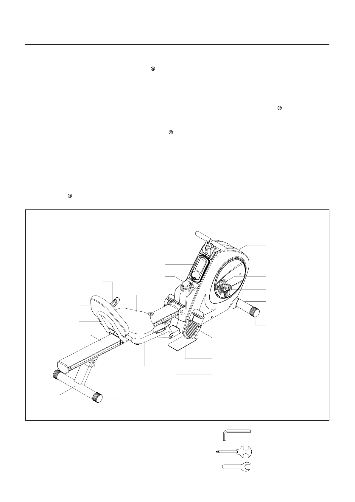
Before reading further, please review the drawing
below and familiarize yourself with the parts that are
labeled.
Read this manual carefully before using the
Conversion II
9003.
Handlebar
Although Sta min a con structs its products with the
finest materials and uses the highest standards of
manufacturing and quality control, there can
sometimes be missing parts or incorrectly sized
parts. If you any question s or problems with the parts
included with your Conversion II
not return the product. Contact us FIRST!
If a part is missing or defective, please call us toll
free at 1-800-375-7520 (in the U.S.). Our Customer
Service Staff is available to a ssist you from 7:30 A.M.
to 5:00 P .M. (Central T ime) Monday through Thursday
and 8:00 A.M. to 3:00 P.M. (Central T i me) on Friday.
If you would like to contact us on-line, go to our
website at www .stamin aproducts.com a nd a ccess the
Customer Service section.
Be sure to have the name and model number of
the product available when you contact us.
9003, please do
Hand Pulse Sen sor
Back Cushion
Seat Carriage
Rail
Rear Support
Top Cover
Meter
Tension Knob
Seat
Handrail
Endcap
Right Cover
Crank Cover
Right Pedal Strap
Right Pedal
Front Stabilizer
Endcap
Foot Pedal
Foot Plate
Main Fra me
THE FOLLOWING TOOLS ARE INCLUDED FOR ASSEMBLY :
4
Allen Wrench (6mm)
Combination Wrench
Wrench (17mm)
Page 4
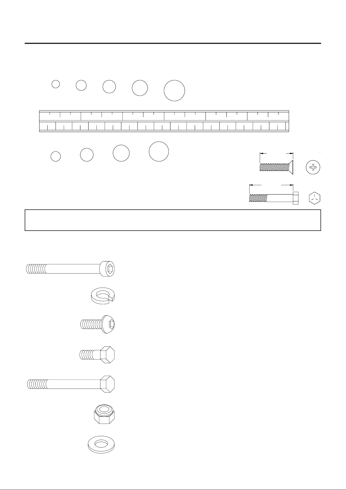
HARDWARE IDENTIFICATION CHART
This chart is provided to help identify the hardware used in the assembly process. Place the washers, the
end of the bolts, or screws on the circles to check for the corre ct di ameter. Use the small scale to check the
length of the bolts and screws.
3/16" 5/16" 1/2"3/8"1/4"
INCHES
11/2021/2 31/2 41/2 51/2 61/2
0 10 20 30 40 50 60 70 80 90 100 110 120 130 140 150
MILLIMETERS
6 8 10 12
NOTICE: The length of all bolts and screws except those with flat hea ds is
measured from below the head to the end of the bolt or screw.
Flat head bolts and screws are measured from the top of the
head to the end of the bolt or screw.
After unpacking the unit, open the hardware bag and make sure that you have all the following items.
Some hardware may be already attached to the part.
length
length
in.
mm.
Part No. and Description Qty
81 Bolt, Socket Hea d (M8 x 1.25 x 70mm) 2
89 Lock Washer (M8) 2
94 Bolt, Button Head (M8 x 1.25 x 15mm) 3
114 Bolt, Button Head (M8 x 1.25 x 12mm) 4
95 Bolt, Hex Hea d (M6 x 1 x 15mm) 4
96 Bolt, Hex Hea d (M6 x 1 x 30mm) 4
97 Bolt, Hex Hea d (M8 x 1.25 x 16mm) 4
101 Bolt, Hex Hea d (M10 x 1.5 x 85mm) 1
102 Bolt, Hex Hea d (M10 x 1.5 x 95mm) 1
103 Bolt, Hex Hea d (M10 x 1.5 x 125mm) 1
105 Nylock Nut (M10 x 1.5) 3
109 Large Washer (M8 x ø 23 ) 2
5
Page 5
ASSEMBLY INSTRUCTIONS
Place all parts from the box in a cleared area and position them on the floor in front of you. Remove all
packing materi als from your area a nd pla ce them ba ck into the box. Do not dispose of the pa cking materials
until assembly is completed. Read each step carefully before beginning. If you are missing a part please
call our toll-free number for assistance 1 (800) 375-7520 or e-mail us at:
parts@staminaproducts.com
R
L
R
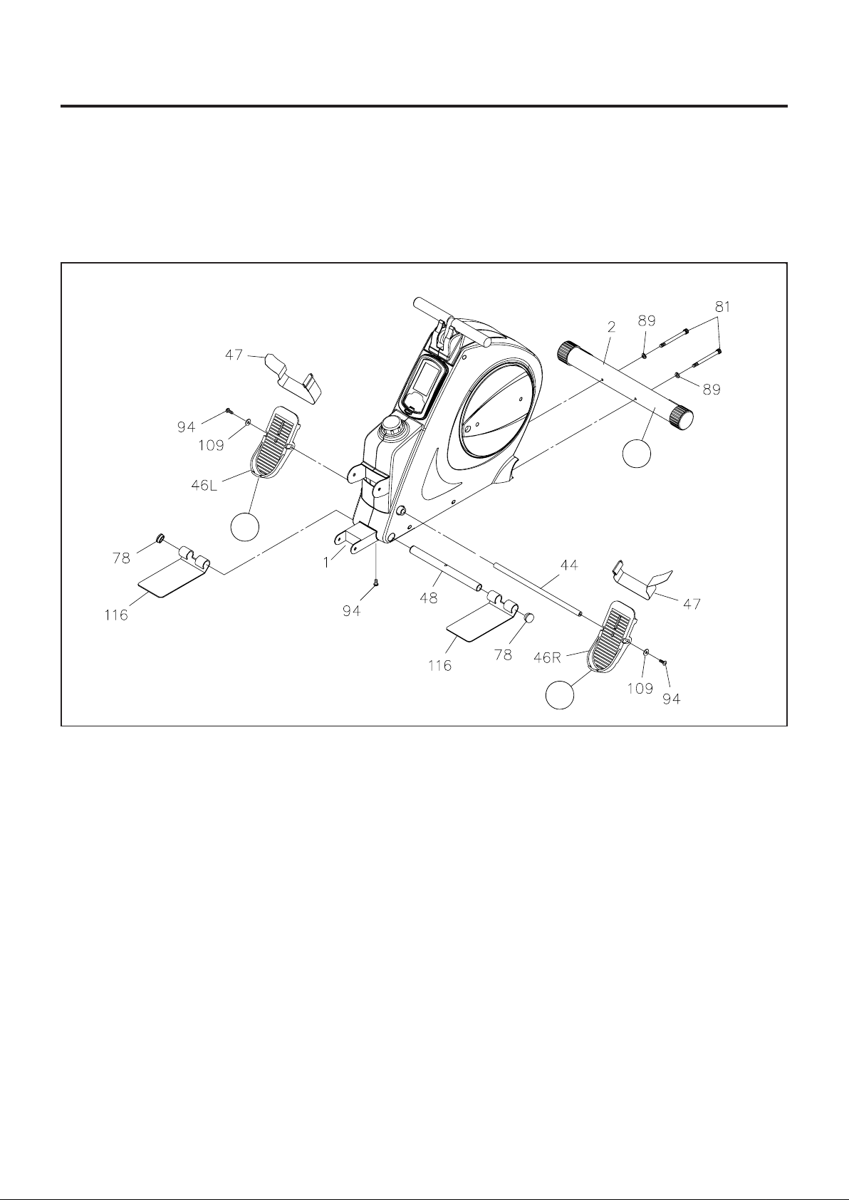
STEP 1: There is a "R" decal on one end of the FRONT ST ABILIZER(2). Attach the FRONT ST ABILIZER(2)
onto the MAIN FRAME(1) with the "R" decal end at right side and secure with SOCKET HEAD BOLTS
(M8x1.25x70mm)(81) and LOCK WASHERS(M8)(89).
STEP 2: Insert the STOPPER TUBE(48) through the MAIN FRAME(1) a nd secure with BUTT ON HEAD
BOLT (M8x1.25x15mm)(94). Slide the FOOT PLATES(116) on both sides of the STOPPER TUBE(48).
Press the DOME PLUGS(25mm)(78) into both ends of the STOPPER TUBE(48).
NOTE:
STEP 3: Insert the PEDAL SHAFT(44) through the MAIN FRAME(1). Place the RIGHT FOOT PEDAL
ASSEMBLY(46R) onto the right end of the PEDAL SHAFT(44) and place the LEFT FOOT PEDAL
ASSEMBLY(46L) onto the left end. Secure the FOOT PEDALS with BUTTON HEAD BOLTS
(M8x1.25x15mm)(94) and LARGE WASHERS(M8)(109) at both ends of the PEDAL SHAFT(44).
NOTE:
The PEDAL STRAPS(47) are pre-assembled to the FOOT PEDALS(46). The pedal and strap
a ssembly for the left side ha s a "L" decal. The pedal a nd stra p a sse mbly for the right side ha s a "R"
decal.
You need to use two Allen W renche s to tighten the BUTT ON HEAD BOLTS(M8x1.25x15mm)(94)
at both ends of the PEDAL SHAFT(44) at the same time.
6
Page 6
ASSEMBLY INSTRUCTIONS
(100) BOLT
STEP 4
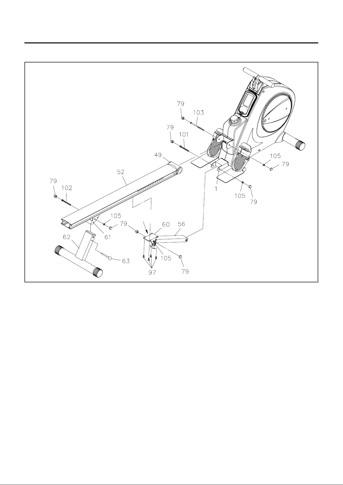
Attach the SUPPORT BRACKET(60) onto the RAIL(52) with HEX BOLTS(M8x1.25x16mm)(97). Press
the NUT CAPS(79) onto NYLOCK NUT(M10x1.5)(105) and HEX BOLT(M10x1.5x75mm)(100).
STEP 5
Attach the RAIL(52) onto the MAIN FRAME(1) by sliding the RAIL PIVOT(49) into the bra cket on the MAIN
FRAME(1) and securing with HEX BOL T(M10x1.5x125mm)(103) a nd NYLOCK NUT(M10x1.5)(105). Press
the NUT CAPS(79) onto HEX BOLT(M10x1.5x125mm)(103) and NYLOCK NUT(M10x1.5)(105).
STEP 6
Connect the lower end of the SUPPORT TUBE(56) to the MAIN FRAME(1) with HEX BOL T(M10x1.5x85mm)
(101) and NYLOCK NUT(M10x1.5)(105). Press the NUT CAPS(79) onto HEX BOL T(M10x1.5x85mm)(101)
and NYLOCK NUT(M10x1.5)(105).
STEP 7
Attach the REAR SUPPORT(62) into the REAR SUPPORT BRACKET(61) located on the RAIL(52) with
HEX BOLT(M10x1.5x95mm)(102) and NYLOCK NUT(M10x1.5)(105). Lock the REAR SUPPORT(62) in
position with the PULL PIN(63). Press the NUT CAPS(79) onto HEX BOLT(M10x1.5x95mm)(102) and
NYLOCK NUT(M10x1.5)(105).
7
Page 7
ASSEMBLY INSTRUCTIONS
Release
NOTE: Be careful not to damage the PULSE SENSOR WIRES(73, 74) while doing assembly Step 8 to
Step 10.
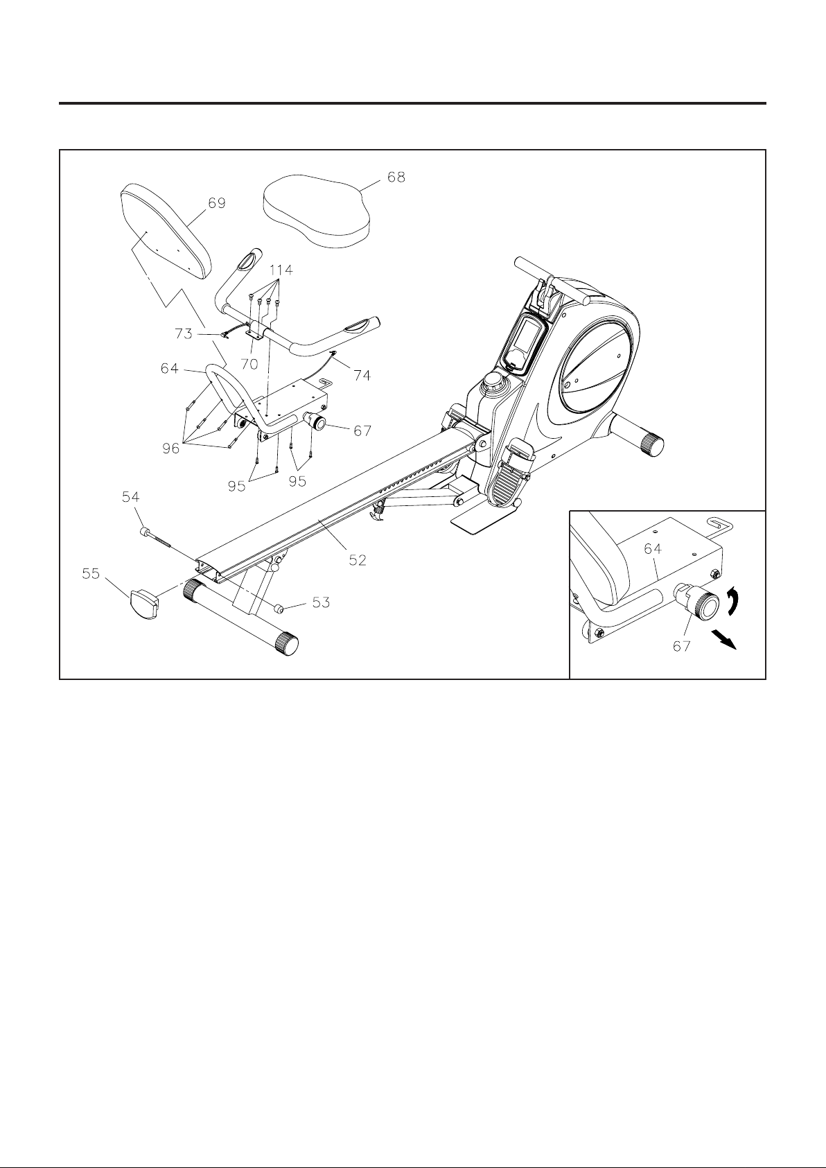
STEP 8
Attach the HANDRAIL(70) onto the SEA T CARRIAGE(64) with BUTTON HEAD BOL TS(M8x1.25x12mm)
(114).
STEP 9
Attach the SEAT(68) onto the SEAT CARRIAGE(64) with HEX BOLTS(M6x1x15mm)(95). Attach the
BACK CUSHION(69) onto the SEAT CARRIAGE(64) with HEX BOLTS(M6x1x30mm)(96).
STEP 10
Turn the knob of the SPRING PIN(67) counterclockwise and lock the knob in the release position, refer to
the inset drawing. Slide the SEAT CARRIAGE ASSEMBLY(64) onto the RAIL(52).
Press the RAIL CAP(55) into the back end of the RAIL(52). Insert the STOPPER BOLT(54) through the
RAIL(52) and RAIL CAP(55) to bolt them together with the STOPPER(53). Please verify that the other
STOPPER BOLT(54) at the front end of RAIL(52) wa s assembled at the factory.
8
Page 8

ASSEMBLY INSTRUCTIONS
STEP 11
NOTE:
Thread the RIGHT PEDAL(41) onto the RIGHT CRANK(37) located at inside of the CRAN K COVER(35) as
shown. Tighten the pedal securely. Select the RIGHT PEDAL STRAP(42) which has R marked on the
bottom side of the stra p. Sna p the three hole end onto the in side edge of the RIGHT PEDAL(41). Sna p the
other end onto the outside edge of the RIGHT PEDAL(41) with the R mark on the bottom of the RIGHT
PEDAL STRAP(42). Select adjustment hole s which allow your foot to be easily removed from the pedals.
Do the same way to attach the LEFT PEDAL(39) onto the LEFT CRANK(36) and snap the LEFT PEDAL
STRAP(40) onto the LEFT PEDAL(39).
The RIGHT PEDAL(41) has R stamped on the end of the pedal shaft. The RIGHT PEDAL(41) ha s
right hand thre ads a nd is tightened by turning clockwise. The LEFT PEDAL(39) has L stamped on
the end of the pedal shaft. The LEFT PEDAL(39) ha s left ha nd thre ads a nd is tightened by turning
counter clockwise.
STEP 12
Refer to the inset drawing. Plug the PULSE SENSOR WIRE(73) into the socket of PULSE COIL WIRE(74)
located on the SEAT CARRIAGE(64). Plug the PULSE COIL WIRE(74) into the socket of PULSE
CONNECTION WIRE(75) located on the bracket on the MAIN FRANE(1).
9
Page 9

OPERATIONAL INSTRUCTIONS
USING THE ELECTRONIC METER
POWER ON:
POWER OFF:
Pedal movement or press any button.
Automatic shut off after 4 minutes of in activity.
FUNCTION BUTTONS :
ENTER :
MODE : Press and release to select the function to display on
RESET :
& :
Press this button to enter setting mode.
Press and rele ase to select e ach function for preset target
values for TIME, CAL, PULSE, and DIST.
the screen.
Press the button and hold it down for two seconds to
reset all functions to zero.
In the setting mode, press the button to reset the setting
values to zero for TIME, CAL, and DIST.
In the stop mode, press the button to reset the value
displaying on the screen to zero for CAL and DIST.
Press the button and hold it down for two seconds to
reset all functions to zero.
These two buttons for setting target value s of TIME, CAL,
PULSE, and DIST .
FUNCTIONS:
SCAN:
TIME:
SPEED:
CALORIE:
PULSE:
RPM:
DISTANCE:
Automatically scans TIME, SPEED, CALORIE, PULSE, RPM, a nd DISTANCE in sequence
with a change every six seconds. Press and release the MODE button until the "SCAN"
appear on the display.
Displays the time, from 1 sec. up to 99:59 minutes. Counts down from preset value.
Displays the current speed, from zero to 999.9 Mile/Hr .
Displays the calorie consumption, from zero to 999.9 Kcal.
The calorie readout is an estimate for an average user. It should be used only as a
comparison between workouts on this unit.
Displays your pulse rate in beats per minute. To display pulse, select the PULSE MODE
and gra sp the pulse sensors on the ha ndlebars, one in ea ch hand. The heart icon will begin
fla shing when the ELECTRONIC METER sense s your pulse. Your pulse will be displayed
a pproximately five (5) seconds after the heart icon is displayed. If the heart icon does not
appear, relax your grip or change your grip on the pulse sensors.
Counts down from preset value.
If you preset the PULSE value, the meter will warn you with an audible alarm when
your pulse exceeds the set value. Stop exercising until your pulse comes down.
Displays crank RPM (revolutions per minute), from zero to 999 rpm.
Displays distance, from the time the meter is turned on, to 999.9 miles.
preset value.
Counts down from
10
Page 10

OPERATIONAL INSTRUCTIONS
HOW TO INSTALL AND REPLACE BATTERIES:
Squeeze the lug at the bottom on the Meter to open
1.
the meter cover.
The meter operates with two AA batteries, two
2.
batteries included. Refer to the illustration to install
or replace the batteries.
NOTE:
Do not mix a new battery with an old battery.
1.
Use the sa me type of battery. Do not mix an alk aline
2.
battery with another type of battery.
Rechargeable batterie s are not recommended.
3.
AA Batteries
Lug
LOAD ADJUSTMENT
To increase the load, turn the TENSION KNOB(27) clockwise. To
decrea se the load, turn the TENSION K NOB(27) counterclockwise.
There are eight levels for the load adjustment.
NOTE: The load will increase as you pedal faster.
11
Page 11
OPERATIONAL INSTRUCTIONS
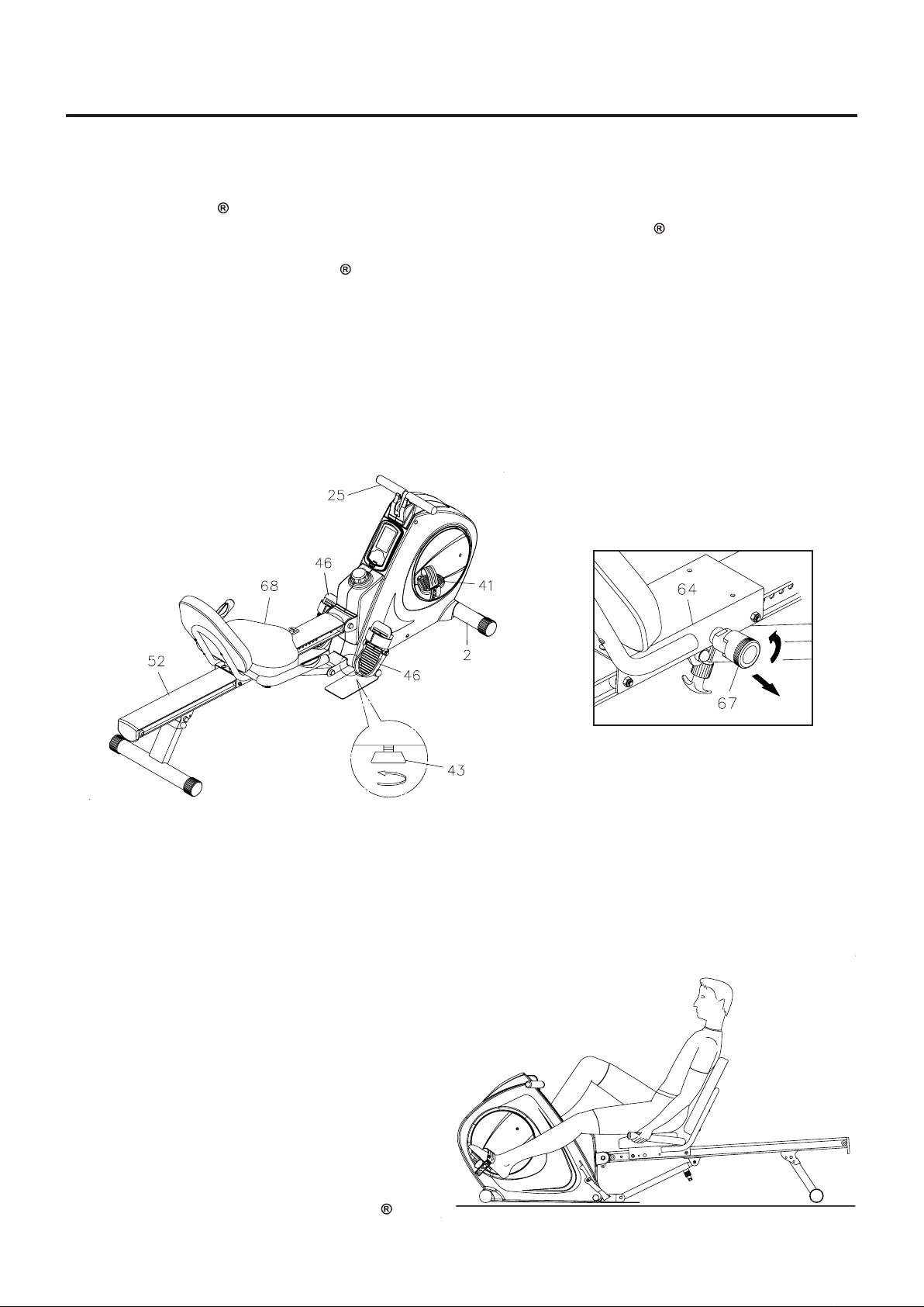
RECUMBENT BIKE MODE AND ROWER MODE
Your Conversion II 9003 can be used in the Recumbent Bike mode or the Rower mode. When the
SPRING PIN(67) locks the SEA T ASSEMBLY to the RAIL(52), the Conversion II 9003 is in the Recumbent
Bike mode. When the SPRING PIN(67) is in the Release position, the SEA T ASSEMBLY is not locked to
the RAIL(52) and the Conversion II 9003 is in the Rower mode.
RECUMBENT BIKE MODE: Pull the knob on the SPRING PIN(67), turn it clockwise and release the
knob to allow it to lock the seat in position. Sit on the seat and pedal with the PEDALS(39, 41).
ROWER MODE: Pull the knob on the SPRING PIN(67) and turn it counter-clockwise to lock it in the
release position. Refer to the inset drawing. This will allow the SEAT ASSEMBLY to slide freely on the
RAIL(52). To workout, sit on the seat, place your feet on the FOOT PEDALS(46) and pull on the
HANDLEBAR(25).
NOTE:
If the FRONT STABILIZER(2) raises off the floor during use, adjust the STAND(43) to a higher
position.
Release
CAUTION: Always verify that the SPRING
PIN(67) is in the correct position
before you begin your workout.
SEA T ADJUSTMENT
Proper seat adjustment is important for Recumbent Bike mode.
Pull the knob on the SPRING PIN(67) and slide the SEA T ASSEMBL Y forward or ba ckward to adjust the
1.
seat. Release the knob on the SPRING PIN(67) and ma ke sure it is inserted into one of the adjustment
holes in the RAIL(52).
Sit on the seat and pla ce your feet on the pedals.
2.
Y ou should be able to move through a complete
pedal stroke without locking your knees or
shifting your hips on the seat. The seat is too
close to the pedals if you have more than a slight
bend in your knees at the bottom of the pedal
stroke. The seat is too far from the pedals if you
have to completely straighten your knees at the
bottom of the pedal stroke. Refer to the
illustrations below .
WARNING: Do not attempt to adjust the seat while
you are on the Conversion II
9003.
12
Page 12

OPERATIONAL INSTRUCTIONS
WORKOUT FUNCTIONS
Your Conversion II 9003 can be used a s the Rower or the Recumbent Bike. Ple ase workout a s f ollowing
illustrations.
ROWER RECUMBENT BIKE
BACK & ABDOMINAL
Lock the Seat at proper position of rear part of
the Rail. By pulling the handlebar in different
ways, you can do the following exercises with
your Conversion II
9003.
BICEPS CURL
UPRIGHT ROW
13
Be sure to step on the iron Foot Plates.Be sure to step on the iron Foot Plates.
Page 13

OPERATIONAL INSTRUCTIONS
Unlock the Seat from the Rail. Hook the
Handlebar to the steel wire Hook at the front of
the Seat. You can do the following exercises
with your Conversion II
BUTTOCKS LEG EXTENSION
9003.
LEG STRETCH
Be sure to step on the iron Foot Plate.
Be sure to step on the iron Foot Plate.
MAINTENANCE
The safety and integrity designed into the Conversion II 9003 can only be maintained when the Conversion
9003 is regularly examined for da mage and wear. Special attention should be given to the following:
II
Adjust the TENSION KNOB(27) and verify that the Magnetic System provides tension. The Magnetic
1.
System should provide many years of use.
Clean the roller tracks in the RAIL(52) with an absorbent cloth.
2.
It is the sole responsibility of the user/owner to ensure that regular maintenance is performed.
3.
Verify that all nuts a nd bolts are present a nd properly tightened. Repla ce missing nuts a nd bolts. T ighten
4.
loose nuts and bolts.
Worn or da maged components shall be repla ced immedi ately or the Conversion II
5.
service until repair is made.
Only Sta mina Products supplied components shall be used to maintain/repair the Conversion II
6.
Keep your Conversion II
7.
9003 clean by wiping with an absorbent cloth after use.
14
9003 removed from
9003.
Page 14

STORAGE
1.
To store the Conversion II 9003 simply keep it in a clean dry place.
2.
To avoid damage to the electronics meter , re move the batteries bef ore storing the Conversion II
for one year or more.
3.
Move the Conversion II
move the Conversion II
move and the Seat Carriage may pinch your hand or f ingers.
4.
Follow the following process to fold The Conversion II
Adjust and lock the seat in position with at lea st one adjustment hole visible in front of the seat.
a.
NOTE: This will prevent the seat from damaging the covers.
Remove the PULL PIN(63) a nd swing the REAR SUPPORT(62) toward the front.
b.
NOTE: This will allow you to pull out the RELEASE KNOB(59) easily.
Pull out the RELEASE KNOB(59) and fold up the RAIL(52). Make sure the RAIL(52) is locked
c.
securely in folded position by RELEASE K NOB(59).
Lock the REAR SUPPORT(61) in folded position with the PULL PIN(63).
d.
9003 with the moving wheels on the Front Stabilizer. Grasp the Rail Cap to
9003. Do not use the Se at to move the Conversion II 9003. The Seat will
9003 as illustrated for easy storage.
A
9003
D
C
Grasp Here
To Move
B
UNFOLD THE Conversion II 9003
Pull out the RELEASE KNOB(59) a nd unf old the RAIL(52). Ma ke sure the RAIL(52) is locked se curely
a.
in the unfolded position by RELEASE KNOB(59).
Remove the PULL PIN(63) and swing the REAR SUPPORT(62) backward, then lock the REAR
b.
SUPPORT(61) in position with the PULL PIN(63).
A
15
B
Page 15
CONDITIONING GUIDELINES
How you begin your exercise program depends on your physical condition. If you have been inactive for
several years or are severely overweight, start slowly a nd increase your workout time gradually. Increase
your workout intensity gradually, too, by monitoring your heart rate while you exercise.
Remember to follow these essentials:
Have your doctor review your training and diet programs.
Begin your training progra m slowly with realistic goals that have been set by you and your physician.
Warm up before you exercise and cool down after you work out.
Take your pulse periodically during your workout and strive to stay within a range of 60% (lower
intensity) to 90% (higher intensity) of your maximum he art rate zone. Start at the lower intensity and
build up to higher intensity as you become more aerobically fit.
If you feel dizzy or lightheaded you should slow down or stop exercising.
Initially you may only be able to exercise within your target zone for a few minutes; however , your a erobic
ca pa city will improve over the next six to e ight weeks. It is i mporta nt to pa ce yourself while you exercise so
you don’t tire too quickly.
To determine if you are working out at the correct intensity, use a he art rate monitor or use the table below .
For effective aerobic exercise, your heart rate should be maintained at a level between 60% and 90% of
your maximum heart rate. If just starting a n exercise program, work out at the low end of your target heart
rate zone. As your a erobic ca pacity i mproves, gradually increase the intensity of your workout by increasing
your heart rate.
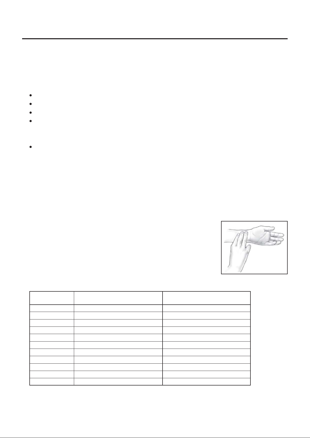
Measure your heart rate periodically during your workout by stopping the
exercise but continuing to move your legs or walk around. Place two or three
fingers on your wrist and take a six second heartbeat count. Multiply the
results by ten to find your heart rate. For exa mple, if your six second he artbeat
count is 14, your heart rate is 140 beats per minute. A six second count is
used because your heart rate will drop rapidly when you stop exercising.
Adjust the intensity of your exercise until your heart rate is at the proper level.
Target Heart Rate Zone Estimated by Age*
Age
20 years
25 years
30 years
35 years
40 years
45 years
50 years
55 years
60 years
65 years
70 years
Target Heart Rate Zone
(55%-90% of Maximum Heart Rate)
110-180 beats per minute
107-175 beats per minute
105-171 beats per minute
102-166 beats per minute
99-162 beats per minute
97-157 beats per minute
94-153 beats per minute
91-148 beats per minute
88-144 beats per minute
85-139 beats per minute
83-135 beats per minute
Average Maximum
Heart Rate 100%
200 beats per minute
195 beats per minute
190 beats per minute
185 beats per minute
180 beats per minute
175 beats per minute
170 beats per minute
165 beats per minute
160 beats per minute
155 beats per minute
150 beats per minute
wrist pulse
For cardiorespiratory training benefits, the American College of Sports Medicine re commends working
*
out within a heart rate range of 55% to 90% of maxi mum he art rate. To predict the maximum heart
rate, the following formula was used: 220 - Age = predicted maximum heart rate
16
Page 16
WARM-UP and COOL-DOWN
Warm-up The purpose of warming up is to prepare your body f or exercise and to mini mize injuries. Warm
up for two to five minutes before strength-training or aerobic exercising. Perform activities that raise your
heart rate and warm the working muscle s. Activitie s may include brisk walking, jogging, jumping ja cks, jump
rope, and running in place
Stretching Stretching while your muscles are warm after a proper warm-up and again after your strength
or aerobic training session is very important. Muscles stretch more easily at these times because of their
elevated temperature, which greatly reduces the risk of in jury . Stretches should be held for 15 to 30 seconds.
Do not bounce.
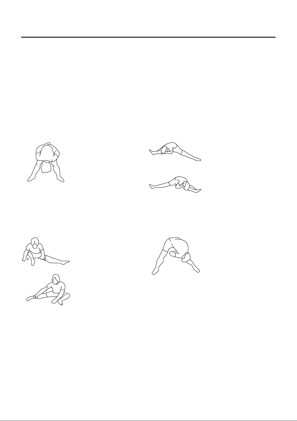
Suggested Stretching Exercises
Lower Body Stretch
Place feet shoulder-width
apart and lean forward.
Keep this position for 30
seconds using the body as a
natural weight to stretch the
backs of the legs.
DO NOT BOUNCE!
When the pull on the back of
the legs lessen, try a lower
position gradually.
Bent Torso Pulls
While sitting on the floor,
have legs apart one leg
straight and one knee bent.
Pull the chest down to touch
the thigh on the leg that is
bent and twist at the waist.
Hold this position at least 10
seconds. Repeat 10 times
on each side.
Floor Stretch
While sitting on the floor,
open the legs as wide as
possible. Stretch the upper
body toward the knee on the
right leg by using your arms
to pull your chest to your
thighs. Hold this stretch 10
to 30 seconds.
DO NOT BOUNCE!
Do this stretch 10 times.
Repeat the stretch with the
left leg.
Bent Over Leg Stretch
Stand with feet shoulderwidth apart and lean forward
as illustrated. Using the
arms, gently pull the upper
body towards the right leg.
Let the head hang down.
DO NOT BOUNCE!
Hold the position a minimum
of 10 seconds. Repeat
pulling the upper body to the
left leg. Do this stretch
several times slowly.
Remember always to check with your physician before starting any exercise program.
Cool-Down The purpose of cooling down is to return the body to its normal, or near normal, resting state
at the end of ea ch exercise se ssion. A proper cool-down slowly lowers your heart rate a nd allows blood to
return to the heart. Y our cool-down should include the stretche s listed above a nd should be completed after
each strength-training session.
17
Page 17

FRONT
PRODUCT PARTS DRAWING
BACK
18
Page 18

PARTS LIST
DIAGRAM# PART NAME QTY
1 Main Frame 1
2 Front Stabilizer 1
3 Axle 1
4 Pulley 1
5 Strap Wheel 1
6 Connection Wheel 1
7 One Way Bearing (3520) 1
8 Bearing (6004 zz) 4
9 C Ring (20mm) 2
10 Bearing Housing 2
11 V-Ribbed Belt 1
12 Idler Arm 1
13 Idler Wheel 1
14 Idler Wheel Spacer 1
15 Tension Spring 1
16 Magnetic System 1
17 Bungee Cord 1
18 Bungee wheel 3
19 Wheel Bushing 3
20 Wheel Spacer 3
21 Stra p 1
22 Strap Roller 2
23 Roller Axle 1
24 Roller Spa cer 2
25 Handlebar 1
26 Foa m Grip 2
27 Tension Knob 1
28 Magnet 1
29 Sensor Wire 1
30 Meter 1
31 Top Cover 1
32 Meter Bottom Cover 1
33 Left Cover 1
34 Right Cover 1
35 Crank Cover 2
36 Left Crank 1
37 Right Crank 1
38 Flange Bolt (M8 x 1.25 x 25mm) 3
39 Left Pedal 1
40 Left Pedal Strap 1
41 Right Pedal 1
42 Right Pedal Strap 1
43 Stand 1
44 Pedal Shaft 1
45 Spacer 2
46 Foot Pedal 2
47 Pedal Strap 2
48 Stopper Tube 1
19
Page 19

PARTS LIST
DIAGRAM# PART NAME QTY
49 Rail Pivot 1
50 Pivot Bushing 2
51 Rail Connection Cap 1
52 Rail 1
53 Stopper 2
54 Stopper Bolt 2
55 Rail Cap 1
56 Support Tube 1
57 Inner Support Tube 1
58 Bushing 1
59 Release Knob 1
60 Support Bracket 1
61 Rear Support Bracket 1
62 Rear Support 1
63 Pull Pin 1
64 Seat Carriage 1
65 Seat Roller 4
66 Seat Roller Spa cer (ø8 x ø12 x 6.5mm) 4
67 Spring Pin 1
68 Seat 1
69 Back Cushion 1
70 Handrail 1
71 Foa m Grip 2
72 Pulse Sensor Plate 2
73 Pulse Sensor Wire 1
74 Pulse Coil Wire 1
75 Pulse Connection Wire 1
76 Moving Wheel 2
77 Round Endcap (60mm) 4
78 Dome Plug (25mm) 4
79 Nut Cap (M10) 8
80 Carriage Bolt (M8 x 1.25 x 60mm) 3
81 Bolt, Socket Head (M8 x 1.25 x 70mm) 2
82 Screw, Round Head (M4 x 20mm) 7
83 Screw, Round Head (M4 x 25mm) 2
84 Screw, Round Head (M5 x 18mm) 8
85 Screw , Round Head (M5 x 0.8 x 15mm) 1
86 Nylock Nut (M8 x 1.25 x 6.2mm thick) 4
87 Bolt, Socket Head (M5 x 0.8 x 15mm) 7
88 Bolt, Round Head (M6 x 1 x 15mm) 4
89 Lock Washer (M8) 6
90 Bolt, Flat Head (M8 x 1.25 x 16mm) 4
91 Bolt, Flat Head (M8 x 1.25 x 25mm) 1
92 Bolt, Flat Button Head (M8 x 1.25 x 25mm) 4
93 Bolt, Button Head (M6 x 1 x 12mm) 4
94 Bolt, Button Head (M8 x 1.25 x 15mm) 3
95 Bolt, Hex Head (M6 x 1 x 15mm) 4
96 Bolt, Hex Head (M6 x 1 x 30mm) 4
20
Page 20

PARTS LIST
DIAGRAM# PART NAME QTY
97 Bolt, Hex Head (M8 x 1.25 x 16mm) 8
98 Bolt, Hex Head (M8 x 1.25 x 55mm) 4
99 Bolt, Hex Head (M10 x 1.5 x 45mm) 1
100 Bolt, Hex Head (M10 x 1.5 x 75mm) 1
101 Bolt, Hex Head (M10 x 1.5 x 85mm) 1
102 Bolt, Hex Head (M10 x 1.5 x 95mm) 1
103 Bolt, Hex Head (M10 x 1.5 x 125mm) 1
104 Nylock Nut (M8 x 1.25 x 8mm thick) 5
105 Nylock Nut (M10 x 1.5) 5
106 Flange Nut (M10 x 1.25) 2
107 Washer (M6) 4
108 Washer (M8 x ø16mm) 7
109 Large Washer (M8 x ø23mm) 2
110 Washer (M10) 2
111 One Way Bearing (2520) 1
112 Roller Axle 1
113 Roller Spacer 1
114 Bolt, Button Head (M8 x 1.25 x 12mm) 4
115 Screw, Round Head (M5 x 12mm) 4
116 Foot Plate 2
117 Round Plug (25mm) 2
118 Bolt, Hex Head (M8 x 1.25 x 70mm) 1
119 Large Washer (26 x 38 x 2.0mm thick) 2
120 Large Washer (6 x 32 x 2.0mm thick) 1
121 Large Washer (26 x 34 x 1.0mm thick) 1
122 Rectangular Plug (38mm x 76mm) 1
123 Allen Wrench (6mm) 2
124 Combination Wrench 1
125 Wrench (17mm) 2
126 Manual 1
21
 Loading...