

Page 1

Page 2

Table of Contents
Introduction .................................................................................................................. 3
Before You Begin .......................................................................................................... 4
For DOS/Windows 3.1X Installation .................................................................... 4
For Windows 95/98 Installation ............................................................................ 5
For Windows NT 4.0 Installation .......................................................................... 6
Installing the Modem ................................................................................................... 7
Hardware Installation............................................................................................ 7
Configuring Windows 95...................................................................................... 8
Configuring Windows 95 OEM Service Release 2 ............................................. 9
Configuring Windows 98...................................................................................... 11
Configuring Windows NT 4.00 ............................................................................ 15
Installing and Configuring Software ......................................................................... 18
Installing Communications Software .................................................................... 18
Troubleshooting ............................................................................................................ 19
Appendix A - AT Command Set ................................................................................... 26
AT Commands ........................................................................................................ 26
AT Commands for Testing and Debugging .............................................. 45
S Registers .............................................................................................................. 48
Appendix B - Communications Regulations .............................................................. 60
Proprietary Notice and Disclaimer
Unless otherwise noted, this document and the information herein disclosed are proprietary to ActionTec Electronics, Inc. Any person or entity to whom this document is furnished or who otherwise has possession thereof, by acceptance agrees that it will not be
copied or reproduced in whole or in part, nor used in any manner except to meet the
purposes for which it was delivered.
The information in this document is subject to change without notice and should not be
construed as a commitment by ActionTec. Although ActionTec will make every effort to
inform users of substantive errors, ActionTec disclaims all liability for any loss or damage
resulting from the use of this document or any hardware or software described herein,
including without limitation contingent, special or incidental liability.
Note: PC is a trademark of IBM Corporation. DOS, Window 3.1X, Windows 95/98 and Windows NT are trademarks of Microsoft, Inc. K56flex is a trademark of Lucent Technologies, Inc. and Rockwell International.
2
Page 3

Introduction
Thank you for purchasing the ActionTec DataLink V.90 PCMCIA fax/modem.
The DataLink V.90 gives the portable computer owner the mobility and connectivity solution only a PC Card fax modem can deliver. Its small size and weight
are a perfect match for todays lightweight notebook computers.
The DataLink V.90 supports both the K56flex and ITU-T V.90 Standards for connectivity to the largest number of Internet Service Providers. This dual mode modem
will automatically select the best possible protocol for your connection. Whether
it be faxing, e-mail, or connecting to the Internet, the DataLink V.90 gives the
mobile professional the connectivity solution needed for todays fast-paced environment.
The DataLink V.90 has a programmable feature that enables you to change the
control codes that the modem uses. When new firmware (the commands that make
the modem work) becomes available, you simply download the update utility from
our website and reprogram the modem. This feature allows the modem to keep
pace with any changes that might be made in the future.
In February 1998, Study Group 16 of the ITU-T (International Telecommunications Union, Telecommunication Standardization) agreed on the technical speci-
fications for 56K modems (ITU-T V.90). As with any new standard, implementation will be an ongoing process. It may take some time for the entire industry to
switch from their proprietary methods to the new standard. The ability to change
your modems control code will allow you to keep pace with these changing conditions.
Please visit ActionTecs website regularly for any new drivers available for your
modem. Under the Tech Support section you will find an area for 56K Modem
Upgrades. Our website address is: www.actiontec.com
ActionTec Electronics, Inc.
1269 Innsbruck Drive
Sunnyvale, CA 94089-2928
3
Page 4

Before You Begin
Please read the following tips carefully before attempting to
install your new modem.
For DOS/WINDOWS 3.1X INSTALLATION
Most portable computers sold today include some form of Card and Socket
Services. This software enables the computers internal PCMCIA controller
to operate. If the computer beeps when the modem is inserted, the modem
should be configured and ready to use. If you do not have Card and Socket
Services, follow the procedure for installing the Point Enabler in this section.
Windows 3.1 and Windows for Workgroups 3.11 do not require any special
drivers to communicate with the PC Card fax/modem if you are using your
systems Card and Socket Services software. You only need to install communications software. If the version of the modem you purchased included
communications software, go to the section Installing and Configuring Soft-
ware and follow the installation instructions.
If your computer does not have Card and Socket Services you will need to
install the Point Enabler. This program provides DOS with the necessary
drivers to interface with the modem. However, you will not be able to hot
swap the modem. The Point Enabler will have to be reinstalled any time you
insert or remove the modem. To install the Point Enabler in your system,
insert the installation diskette that came with your modem into the computers
floppy disk drive. Find the file pmxfm.exe and copy it to the root directory
of your default hard drive. The Point Enabler needs to be executed each time
you turn on your computer. This can be done by typing the following command line at the DOS C:> prompt:
pmxfm c=n i=nn <enter>
Where c specifies the COM Port number (from 1 to 4) and i specifies the
Interrupt used (from 1 to 15). Using COM 3 and IRQ 9 will work in most
systems. Once the pmxfm.exe driver has been loaded and is working correctly, you can add the statement to your autoexec.bat file.
Example: pmxfm c=3 i=9 <enter>
You may also need to modify your config.sys file to exclude an address range
when using the Point Enabler. The two examples below show the most effective ranges and will work with the majority of computers. Example A: shows
the most common exclusion range. Example B: may be the preferred setting
4
Page 5
for certain notebooks. Try Example A: first and use Example B: if your results are not satisfactory. Add a line to your config.sys file as follows:
Example A: device=c:\dos\emm386.exe noems x=d000-dfff
Example B: device=c:\dos\emm386.exe noems x=c800-c8ff x=d000-dfff
Remember, the Point Enabler should not be used with any Card and Socket
Services software. It is meant to be used in a computer that does not have its
own PCMCIA Card and Socket Services software and is for a DOS/Windows 3.1X environment only. It should not be used if you have a Cardbus
capable notebook or are running Windows 95/98 or Windows NT.
For WINDOWS 95/98 INSTALLATION
Since a fax/modem is usually the first accessory purchased for a notebook
computer, it is a good idea to check that the computers PCMCIA controller
has been initialized and properly configured for Windows 95/98. Performing
this simple procedure will eliminate the major cause of installation difficulties.
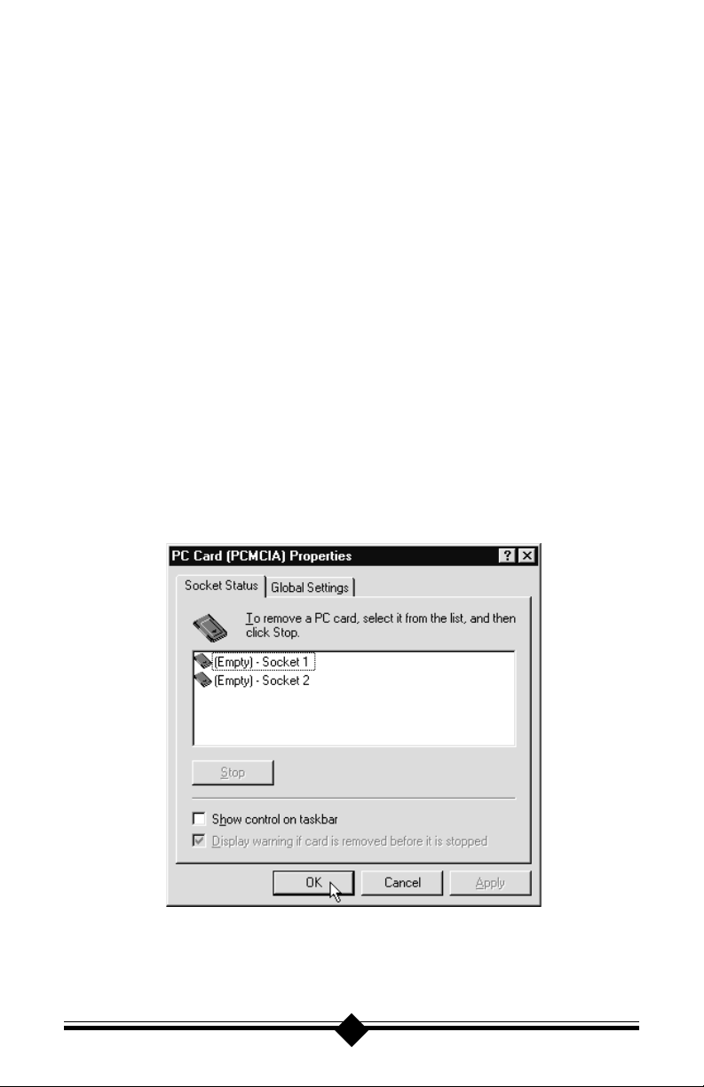
In Windows 95/98, go to: Start-Settings-Control Panel and double-click
the PC Card icon. A properly installed PCMCIA controller will show the
screen below.
If the New Hardware Found panel appears, your computers PCMCIA Ports
have not been configured. Follow the installation instructions on the screen.
You can also read your computers Users Guide for additional instructions on
configuring your PCMCIA ports for Windows 95/98.
5
Page 6
For WINDOWS NT 4.00 INSTALLATION
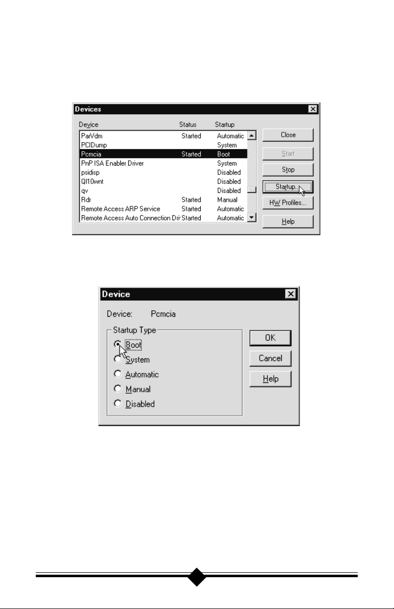
Check that your PCMCIA device setting is selected for boot and started. Go
to: Start-Settings-Control Panel and double-click the Devices icon. Scroll
down to the Pcmcia listing and highlight it by clicking once. If the PCMCIA
device is set correctly, you should see the screen below.
If the Pcmcia device is not set to boot and started, click once on the Startup
button. Select boot and click the OK button. Close the Devices window and
restart Windows NT before proceeding to the installation section
Check that COM 2 is available for the modem to use. COM 2 is the preferred
COM Port for a Windows NT installation. It is recommended that you disable COM2 through your System BIOS Setup routine (read your Computers
User Manual for instructions on how to invoke the BIOS Setup). Once inside
the BIOS Setup, look for a section called Integrated Peripherals. Locate the
entry for COM 2 or COM Port B and disable it. Save your settings before
exiting.
6
Page 7
Installing the Modem
H
ARDWARE INSTALLATION
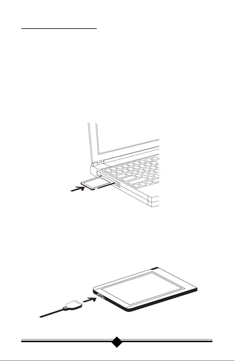
Your DataLink V.90 is housed in a Type II PCMCIA case. It will install in a Type
II or Type III 68 pin PCMCIA slot. PC Card slots are polarized and the modem
will install only in the correct orientation. Notebook computers usually have their
slots located on one side of the computer. To insert the modem, slide it gently into
the opening of the slot keeping it straight. Apply an even pressure until that last
one-half inch, then press firmly until the modem is seated completely into the
notebook. If the PCMCIA slots are recessed into the notebook, it may be difficult
to properly insert modem. Be sure to apply pressure until you feel the modem
click. This is especially true for new notebook computers. The illustration below shows the modem being installed into a typical notebook.
Fig. 1: Installing the Modem
The modem comes with its own dedicated phone cable. This cable has a US standard RJ-11 connector on one end for the phone line and a special connector that
fits into the modem on the other end. Be careful not to push the computer against
an adjacent object when the cable is in place. This may bend the connector causing damage to the pins. Keep the area around the computer clear of large objects
so that you can move the notebook freely without hitting the cable or connector.
Fig. 2: Installing the Cable
7
Page 8
CONFIGURING WINDOWS 95
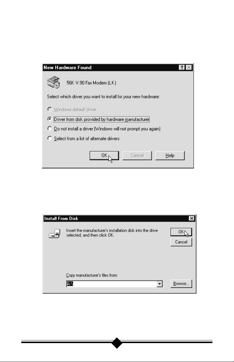
Step 1 Turn on the computer and load Windows 95. Insert the PC Card Modem
into the computers PCMCIA slot. Windows 95 will detect new hardware.
Select Driver from disk provided by hardware manufacturer
then Click OK.
Step 2 Insert the diskette containing the modems Windows 95 .INF files and
click OK
Step 3 If Windows 95 asks for an installation disk, click OK and type A: in the
dialog box that appears and click OK again. Windows will find and load
the .inf files.
8
Page 9
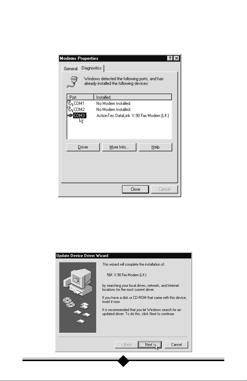
Step 4 To determine what COM port and IRQ is assigned to the modem in Win-
dows 95, click on the Modems icon in Control Panel and select the
Diagnostic tab. Click on the COM Port icon and then on the More Info
button to view the modem properties.
CONFIGURING WINDOWS 95 OEM SR2
Step 1 Turn on the computer and load Windows 95. Insert the PC Card Modem
into an available PCMCIA slot. Windows 95 will detect the modem and
launch the Update Device Driver Wizard dialog box. Insert the diskette containing the modems .INF files and click Next >.
9
Page 10
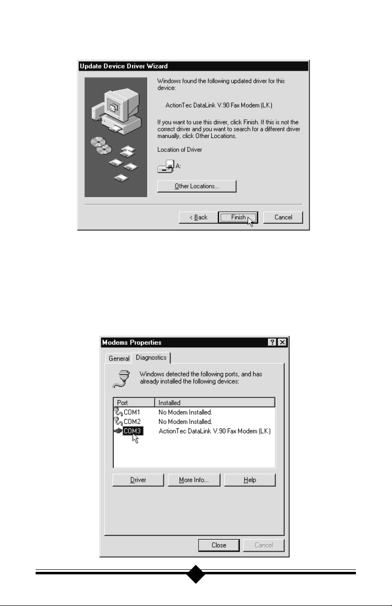
Step 2 After Windows has found the devices drivers for your modem, click the
Finish button.
Step 3 If Windows 95 asks for an installation disk, click OK and using the Other
Locations button, select A: and click OK again. Windows will find and
load the .inf files.
Step 4 To determine what COM port and IRQ is assigned to the modem in Win-
dows 95, click on the Modems icon in Control Panel and select the
Diagnostic tab. Click on the COM Port icon and then on the More Info
button to view the modem properties.
10
Page 11
CONFIGURING WINDOWS 98
Step 1 Turn on the computer and load Windows 98, then insert the diskette con-
taining the modems .inf files into the floppy disk drive.
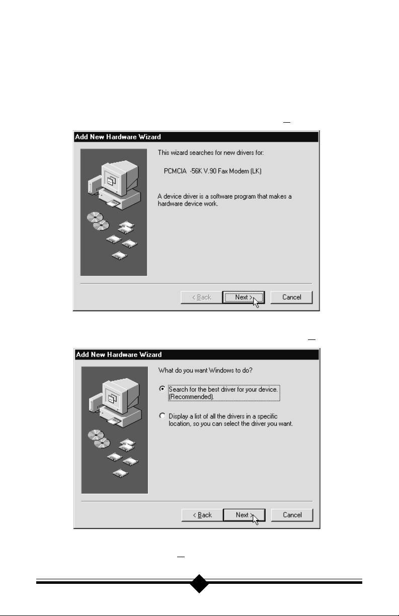
Step 2 Insert the PC Card Fax/Modem into the computers PCMCIA slot. A
Add New Hardware Wizard should appear. Click Next>.
Step 3 Windows will show a screen asking What do you want Windows to do?.
Select: search for the best driver for your device. Click Next>.
Step 4 A search screen will display options to do your search. Put a check on
Floppy disk drives. Click Next>.
11
Page 12
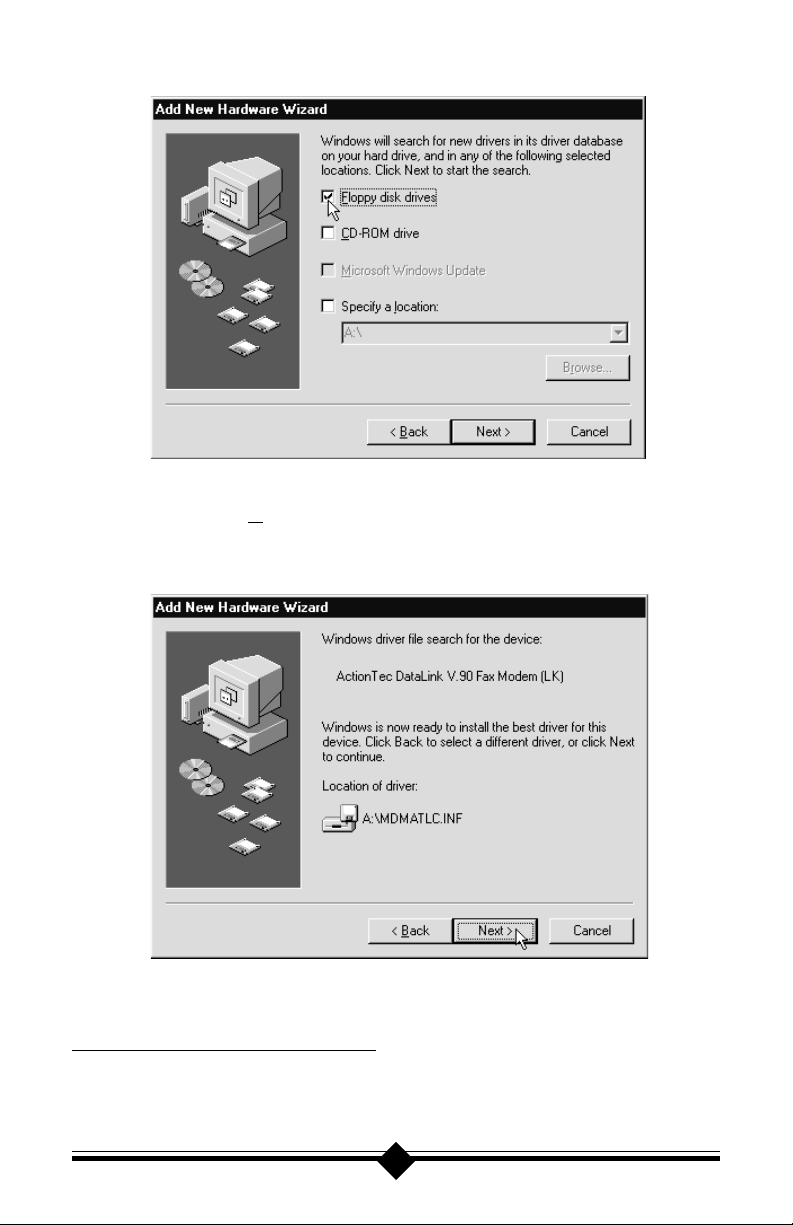
Step 5 Windows 98 will find the PCMCIA Fax/Modem driver on the floppy
drive. Click Next>. (If you receive a Cant Find Driver error, see the
special section at the bottom of this page for an alternate installation
procedure.)
Step 6 At the next screen, click Finish. You are now ready to use your modem.
Special Installation For Windows 98
Depending on your system or your system configuration, Windows 98 may not
find the modems .INF file on the floppy disk. If this situation occurs, abort the
12
Page 13
installation process by clicking the <Back button until you arrive at the following
screen:
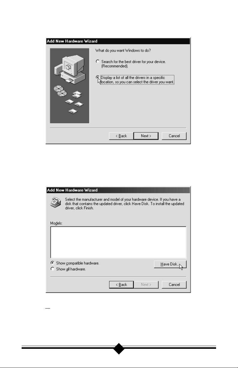
This is the screen for Step 3 shown previously. Instead of selecting Search for the
best driver for your device, select Display a list of all the drivers in a specific
location, so you can select the driver you want. After making the selection, click
the Next> button. The following screen will appear:
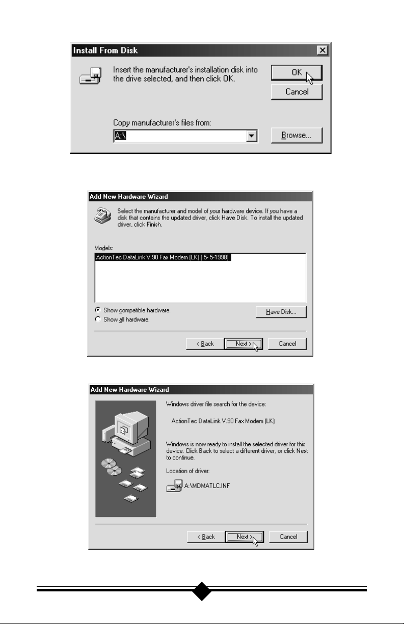
Click the Have Disk button. At the next screen, be sure that the installation diskette that came with your modem is inserted into the computers floppy disk drive.
Verify the A:\ drive is shown in the Copy from box and click the OK button.
13
Page 14
Windows 98 will find the DataLink V.90 modem and properly identify the manufacturer and model. Click the Next> button.
Windows 98 will find the MDMATLC.INF file on the floppy disk. Click Next>.
Click the Finish button on the final screen to complete the installation of your Fax
Modem.
14
Page 15
CONFIGURING WINDOWS NT VER. 4.00
Step 1 This installation assumes that you have disabled COM 2 in your system
BIOS and have set the Pcmcia selection in Control Panel-Devices to
boot and started as outlined in the Before You Begin section.
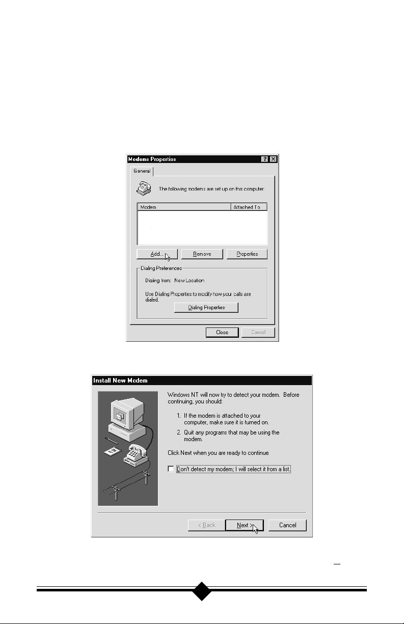
Step 2 Insert the modem into the computer and load Windows NT. Go to Start-
Settings-Control Panel and double-click the Modems icon. At the Mo-
dems Properties window, click the Add button.
Step 3 When the Install New Modem window appears, allow Windows NT to
detect your modem. Click on the Next> button.
Step 4 If a modem is found, Windows NT will query it. In most cases Windows
NT will detect the modem as a Standard Modem. Click on the Change
button.
15
Page 16
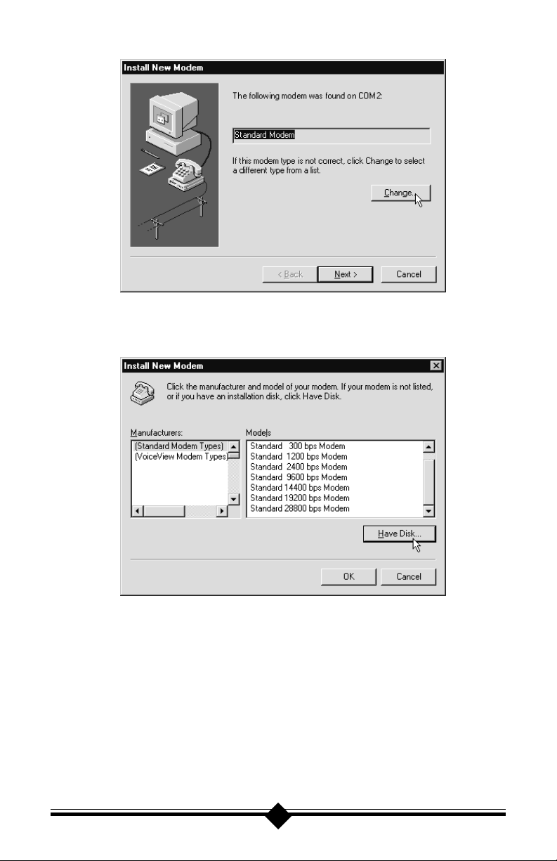
Step 5 Insert the diskette containing the modems .inf files and click the Have
Disk button. When prompted for the path, type A:\ and then click the OK
button.
Step 6 When prompted to select the manufacturer and model of the modem,
click the OK button. At the next screen click the Next> button.
Step 7 Click on the Modems icon in the Control Panel. Verify that Windows
NT has correctly found the modem.
Step 8 If you wish to use your modem to dial into a Windows NT Remote Ac-
cess Server or wish to connect to the Internet, you will need to configure
Dial-up Networking. Go to: Start-Settings-Control Panel and doubleclick the Network icon. Click on the Services folder and select Remote
Access Service. If the Remote Access Service option is not listed (if
16
Page 17
present, go to Step 9), click on the Add button. Scroll-down the menu
and select Remote Access Service. Click on the OK button. Windows
NT may ask for its own disks or CD-ROM for some files. Insert as required. After you have installed Remote Access Service, add the appropriate protocols as directed (i.e.. TCP/IP for Internet Access).
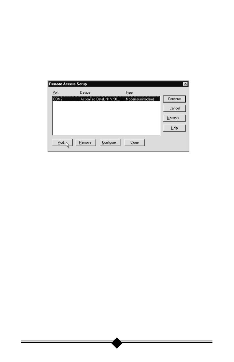
Step 9 At the Remote Access Setup dialog box, click on Add. Select the
RAS Device you wish to add and Click OK.
Step 10 Click Continue to finish the Installation.
Step 11 After Windows NT has completed the binding process, allow Windows
NT to shut down and restart the computer.
17
Page 18

Installing and Configuring Software
INSTALLING COMMUNICATIONS SOFTWARE
If your modem came with a communications software package, it is strongly recommended that you use this software for your modem. Its default installation
parameters have been specially configured to work with this modem. The included
software supports both data and fax modes. To install this software on your computer, follow these easy steps.
Step 1: Insert the diskette containing the communications program into your
computers floppy disk drive.
Step 2: If you are using Windows 95/98, go to My Computer and double-click
the floppy drive icon. Double-click the setup.exe file to install the soft-
ware in Windows 95/98. If you are using Windows 3.1X, go to File-Run
and type in the floppy drive letter followed by setup. This will load the
software for use by Windows 3.1X.
If you wish to use another software package, please be sure that it supports this
modem. Most software manufacturers have a listing of supported modems on their
websites or BBSs. Check these sites to see if this model is supported. If you are
unsure, or your brand of software supports only a few modems, try selecting Hayes
Compatible or Standard Modem. This may work in certain cases. Some software programs allow manual input of parameters. For the users of these programs,
here is a listing of the data/fax command standards supported.
Data: TIA/EIA-602
Fax: TIA/EIA-578 for Class 1 Fax
Init String: AT&F&C1&D2W2
Note: Some programs must be configured to communicate with the modem on the same COM port and or IRQ setting used by the modem.
18
Page 19

Troubleshooting
This section lists some common problems and offers suggestions for a solution.
Before attempting any troubleshooting, it is strongly recommended that you carefully follow the pre-installation procedures outlined in the Before You Begin sec-
tion. These steps have been thoughtfully chosen to help minimize difficulties during the installation of the modem in both Windows 95/98 and Windows NT 4.00.
If you have installed the modem without performing any of the pre-installation
steps, eject the modem from the computer and remove the driver from the Mo-
dems panel. Go to Start-Settings-Control Panel and double-click the Modems
icon. Highlight the modem by clicking once and then click the Remove button.
Restart Windows 95/98 and follow the pre-installation suggestions listed in the
Before You Begin section before attempting a reinstallation. If you have reinstalled the modem but it is still not functioning or Windows does not detect it,
follow the suggestions listed below for your particular symptom. These troubleshooting procedures will correct the majority of installation problems that might
be encountered when installing the modem.
Case 1: Resetting the PCMCIA Controller (Modem Is Not Detected).
Resetting the PCMCIA Socket controller corrects the vast majority of noninstallation difficulties and should be the first step chosen when trying to
remedy a situation where the modem is not detected. Before attempting
this procedure, uninstall the modem using the procedure outlined in the
previous paragraph.
Go to Start-Settings-Control Panel and double-click the System icon.
Select the Device Manager tab to display the device tree. In the device
tree, double-click the PCMCIA Socket icon to expand the socket tree.
Highlight the listed socket device by clicking once on the icon, then click
the Remove button. Exit Device Manager and restart Windows. On startup,
Windows should detect new hardware for the PCMCIA Socket that was
previously removed (If Windows does not detect new hardware, go to
Start-Settings-Control Panel and double-click the PC Card icon). At
the PCMCIA installation screens, choose No, No, and then Finish. The
PCMCIA controller in your system is now reset. Go to Start-Settings-
Control Panel and double-click the PC Card icon. The screen should
say socket 1 & socket 2 empty. Try reinstalling the modem again using
the steps in the Installing The Modem section.
Case 2: Correcting a Cannot Open COM Port Error (Disabling a COM Port)
When Windows displays a Cannot Open COM Port Error, it means that
there are no COM Ports available for the modem to use. To correct this
condition, you must disable any unused COM Ports listed in Windows.
19
Page 20

COM Port 1 (COM 1) is usually required by the system and should not be
removed. Go to Start-Settings-Control Panel. Double-click on the Sys-
tem icon, and select the Device Manager tab. From the device tree, doubleclick the Ports [COM & LPT] icon to expand the Ports tree. COM 1
should be listed. If COM 2,COM 3, or COM 4 are listed, disable them by
clicking once to highlight each port and then click the Properties button.
At the Properties screen, Uncheck Original Configuration, Current (Windows 95a) or check Disable In This Hardware Profile (Windows 95 OSR2).
If there is a message screen, choose yes and click the OK button. If the
COM Port is properly disabled, there will be a red X over the COM Port
icon.
Case 3: Modem is installed as a Standard Modem or some other modem. Not as a
DataLink V.90 Modem. (Windows will not use the driver disk)
When you insert your modem into the computer, Windows 95 detects it as
either new hardware or as hardware that has already been installed at one
time. Under rare circumstances, Windows 95 will see your modem and
identify it as new hardware, but will not use the installation files that you
give it. Instead, it uses some other .inf file, usually one from previously
installed hardware. As a result, your modem does not work with Windows
95 programs like Dial Up Networking (but will work with programs that
access COM Ports). Correcting this condition requires that you know the
version of Windows 95 that you are using. To find the version of Windows
95 on your computer, go to Start-Settings-Control Panel. Double-click
on the System icon. If the version of Windows 95 is 4.00.950 or 4.00.950A,
use the Windows 95a procedure below. If the version of Windows 95 reads
4.00.950B, see the procedure for Windows 95 OSR2. Read these instruc-
tions first before attempting anything. If you feel uncomfortable with renaming files, please ask the assistance of someone who is knowledgable
with Windows files and Windows file extensions.
Windows 95a
Eject the modem from the computer and go to Start-Settings-Control
Panel. Double-click the Modems icon. Highlight the modem by clicking
once and then click the Remove button. Close the control panel and return
to the desktop screen. Do not reboot or restart the system. Now go to
Start-Programs and select MS-DOS Prompt. At the c:> prompt, type in
the following commands in the order listed (Note: if you have renamed
your Windows Directory from C:\Windows, substitute the new name for
Windows in the commands that follow.):
cd c:\windows\inf <enter>
rename *.inf *.bak <enter>
exit <enter>
20
Page 21

If you have correctly typed these statements in, you should now be back at
the Windows Desktop. It is important that you do not reboot or restart the
system at this time. Instead, insert your DataLink V.90 Fax Modem into
the computer and perform the installation using the files provided with the
modem (See the Installing the Modem, Windows 95 section). After you
have finished the installation, return here and follow these very impor-
tant steps. Go to Start-Programs and select MS-DOS Prompt. At the
c:> prompt, type in the following commands in the order listed:
cd c:\windows\inf <enter>
rename oem0.inf oem20.inf
rename *.bak *.inf <enter>
exit <enter>
If everything has been entered and no errors have been issued, your modem and system will be properly configured and ready to use. This procedure renames all of the .inf files in Windows, basically removing them
from the system. This allows you to install the modem and force Windows
to accept the installation files you provide. After the modem has installed,
you then rename all of the .inf files to their proper file extension so that
the hardware they control can be used by the system. This is a complicated but safe procedure if carried out according to the instructions.
Windows 95 OSR2
Eject the modem from the computer and go to Start-Settings-Control
Panel. Double-click the Modems icon. Highlight the modem by clicking
once and then click the Remove button. Close the control panel and return
to the desktop screen. Do not reboot or restart the system. Now go to
Start-Programs and select MS-DOS Prompt. At the c:> prompt, type in
the following commands in the order listed (Note: if you have renamed
your Windows Directory from C:\Windows, substitute the new name for
Windows in the commands that follow.):
cd c:\windows\inf <enter>
rename *.inf *.bak <enter>
cd c:\windows\inf\other <enter>
rename *.inf *.bak <enter>
exit <enter>
If you have correctly typed these statements in, you should now be back at
the Windows Desktop. It is important that you do not reboot or restart the
system at this time. Instead, insert your DataLink V.90 Fax Modem into
the computer and perform the installation using the files provided with the
21
Page 22

modem (See the Installing the Modem,Windows 95 OEM SR2 section). After you have finished the installation, return here and follow these
very important steps. Go to Start-Programs and select MS-DOS
Prompt. At the c:> prompt, type in the following commands in the order
listed:
cd c:\windows\inf <enter>
rename *.bak *.inf <enter>
cd c:\windows\inf\other <enter>
rename *.bak *.inf <enter>
exit <enter>
If everything has been entered and no errors have been issued, your modem and system will be properly configured and ready to use. This procedure renames all of the .inf files in Windows, basically removing them
from the system. This allows you to install the modem and force Windows
to accept the installation files you provide. After the modem has installed,
you then rename all of the .inf files to their proper file extension so that
the hardware they control can be used by the system. This is a complicated but safe procedure if carried out according to the instructions.
Case 4: The modem has been recognized and installed using the files provided,
but Windows HyperTerminal issues Device Not Ready Error.
STEP 1: Check System Resources.
With the modem installed, go to Start-Settings-Control Panel and double-
click the System icon. Select the Device Manager tab. From the device
tree, double-click the Modems icon to show what modems are installed.
If your modem is listed, check that there is no yellow exclamation mark or
red X over the modems telephone icon (if there is, go to STEP 2). If
any other modems are listed, highlight the modem by clicking once on the
telephone icon next to the listed modem and then click on the Remove
button. Shutdown the system and turn off the power. Wait 5 seconds and
turn your computer back on and repeat STEP 1.
STEP 2: Check Modem Properties.
From the Device Manager tab within System Properties, double-click
the Modems icon in the device tree to show what modems are installed.
Highlight your modem by clicking once on the icon and then click the
Properties button. Read the Device Status under the General tab to see if
the device is working properly. Check the Device Usage box and make
sure there is no check mark on Disable in this hardware profile (Win-
dows 95 OEM SR2 only) or (for Windows 95 or 95a) the box labeled
Original Configuration, Current has a check mark . If either of these
22
Page 23

conditions are not as they should be, correct them. Make a note of the
COM Port and IRQ the modem is using. If the Device Status box shows
some error message, it will generally be about a conflict. Go to the Re-
sources tab and read the Conflicting Device List. If a conflict is present,
uncheck the box Use automatic settings and select a configuration that
does not cause conflicts. Manually change the IRQ settings if needed (see
your Windows 95 on-line help file for a more detailed discussion on changing these settings).
STEP 3: Modem Diagnostics.
Go to Start-Settings-Control Panel and double-click the Modems icon.
Your modem should be listed. Highlight the modem by clicking once and
then click on the Diagnostics tab. Highlight the modem by clicking once
on the COM Port icon next to its listing. Now click on the More Info
button. You should see the panel below.
More Info Panel
If the diagnostics window is blank, the modem is not responding. This is
usually a sign that the computers PCMCIA controller is either not installed correctly or has not been initialized. If you have carried out these
three steps and the modem is not functioning, go to the Case 1: listing in
the Troubleshooting section and reset the computers PCMCIA Control-
ler.
23
Page 24

Some Common Problems:
No Dialtone Error
You may have too many devices connected to the phone line. Remove all
other equipment, especially cordless phone recharger bases.
If you are calling from an office, are you using a PBX system. If you
have to dial 9 to reach an outside number, you are using a PBX. Use
the modem only with a regular analog telephone line (PSTN).
Try checking the modem cable. Is it installed securely into the modem?
Apply a little more pressure when installing the cable.
Communications Software Does Not Work
Some communications software packages need to be configured to the
same COM Port and or IRQ as the modem.
If you are trying to send a fax using your communications software, be
sure that the default printer is set to the faxing software. Not to your
external printer.
Does the communications software support this modem? See the Install-
ing and Configuring Software section. If you are using a different software from the one supplied with the modem (some models of this modem may be shipped without communications software), try installing
the supplied software and verify its functionality with the modem.
Nothing Appears On The Screen When I Type In Terminal Mode
Issue the command ATE1 to the modem to enable command echo. This
will let you see what you type.
Cant Connect at 56K
Note: Current FCC regulations limit your maximum connection rate to
53Kbits / s.
The number you are calling may not support V.90 or K56flex protocols.
Some ISPs (Internet Service Providers) have special numbers that you
must call to connect to 56K. Contact your service provider and ask if the
number you are calling supports V.90 or K56flex connections to their
service.
Check the maximum speed setting in the Modem Properties window.
Go to Start-Settings-Control Panel and double-click the Modems icon.
Highlight your modem by clicking once on the icon next to the modem
24
Page 25

and then click the Properties button. Select the General tab and look at
the setting in the Maximum speed box. Make sure this is set to 115200.
You may have other telephone devices connected to the phone line. To
help your modem achieve the best connection possible, remove all extra
devices connected to the telephone line when the modem is in use. This
includes extension phones, answering machines, cordless phone bases,
caller ID boxes, etc. Dont just disconnect the phone cable from the units.
Disconnect the phone cable from the wall. This reduces the load on your
phone line and keeps signal attenuation to a minimum. Not having loose
phone line cords coming from your phone line sockets will help reduce
the possibility of interference being transmitted to the phone line.
If you are attempting to make a call from a hotel or office, are you using
a direct outside line or are you using a PBX hookup? If you have to dial
9 or some other number to reach an outside line, you are using a PBX.
Do not use this modem on any digital or PBX phone system. The modem will not be damaged, but it is not compatible with a digital or digital
PBX phone system. Before using your modem in a hotel or office, verify
that the phone line to be used is compatible with PC fax modems. Try
using the line connected to a fax machine. Fax machines are normally
hooked-up to a direct outside line, not through a PBX or digital phone
system.
The phone line you are using may not support a 56K connection.
25
Page 26

Appendix A: AT Command Set
AT Commands
AT commands are issued to the modem to control the modems operation and
software configuration. AT commands can only be entered while the modem is in
command mode. The format for entering AT commands is:
TYPE: ATXn
where X is the AT command, and n is the specific value for that command.
PRESS: Enter
Any command issued is acknowledged with a response in text format known as
result codes. For multiple AT commands in the same command line, the commands are executed in the order received from the DTE. Should execution of a
command result in an error, or a character not be recognized as a valid command,
execution is terminated, the remainder of the command line is ignored, and the
ERROR result code is issued. Otherwise, if all commands execute correctly, only
the result code associated with the last command shall be issued; result codes for
preceding commands are suppressed.
In the following listing, all commands and command values accepted by the modem are shown; any entries other than those shown cause the ERROR result code.
+++ Escape sequence
The escape sequence allows the modem to exit data mode and enter on-line command mode. While in on-line command mode, you may communicate directly to
your modem using AT commands. Once you are finished, you may return to data
mode using the ATO command. A pause, the length of which is set by the Escape
Guard Time (S12), must be used after an escape sequence is issued. This pause
prevents the modem from interpreting the escape sequence as data. The value of
the escape sequence character may be changed using Register S2.
A/ Repeat Last Command
This command repeats the last command string entered. Do not precede this command with an AT prefix or conclude it by pressing Enter.
A Answer Command
This command instructs the modem to go off-hook and answer an incoming call.
26
Page 27

Bn Communication Standard Setting
This command determines CCITT vs. Bell standard.
B0: Selects CCITT V.22 mode when the modem is at 1200 bits/s.
B1: Selects Bell 212A when the modem is at 1200 bits/s (default).
B2: Unselects V23 reverse channel ( same as B3).
B3: Unselects V23 reverse channel ( same as B2).
B15: Selects V.21 when the modem is at 300 bits/s.
B16: Selects Bell 103J when the modem is at 300 bits/s (default).
Result Codes:
OK n = 0, 1, 15, 16
ERROR Otherwise
Cn Carrier Control
The modem will accept the C1 command without error in order to ensure backward compatibility with communications software that issues the C1 command.
However, this modem does not support the C0 command. The C0 command may
instruct some other modems to not send carrier (i.e., it puts them in a receive-only
mode).
C0: Transmit carrier always off.
C1: Normal transmit carrier switching.
Result Codes:
OK n = 1
ERROR Otherwise
Dn Dial
This command instructs the modem to begin the dialing sequence. The dial string
(n, including modifiers and the telephone number) is entered after the ATD command.
A dial string can be up to 40 characters long. Any digit or symbol (0-9, *, #, A, B,
C, D) may be dialed as touch-tone digits. Characters such as spaces, hyphens, and
parentheses do not count, they are ignored by the modem and may be included in
the dial string to enhance readability.
The following may be used as dial string modifiers:
27
Page 28

L Redials last number. Should be the first character following ATD, ignored
otherwise. The modem displays the dialing string in the following format:
Dialingxxxxxxx where xxxxxxx is the last number dialed.
P Pulse dialing. (e.g. ATDPxxx. Dialing set to pulse as default.)
T Touch-tone dialing (default). (e.g. ATDTxxx. Dialing set to tone as default.)
, Pause during dialing. Pause for time specified in Register S8 before process-
ing the next character in the dial string.
W Wait for dial tone. Modem waits for a second dial tone before processing the
dial string.
@ Wait for quiet answer. Wait for five seconds of silence after dialing the num-
ber. If silence is not detected, the modem sends a NO ANSWER result code
back to the user.
! Hook flash. Causes the modem to go on-hook for 0.5 seconds and then re-
turn to off-hook.
; Return to command mode. Causes the modem to return to command mode
after dialing the number, without disconnecting the call.
^ Disable data calling tone transmission.
S=n Dial a telephone number previously stored using the &Zn=x command (see
the &Zn=x command for further information). The range of n is 0-3.
$ Bong tone detection.
En Echo Command
This command controls whether or not the characters entered from your computer
keyboard are echoed back to your monitor while the modem is in command mode.
E0: Disables echo to the computer.
E1: Enables echo to the computer (default).
Result Codes:
OK n = 0, 1
ERROR Otherwise
Fn On-line Data Character Echo Command
This command determines if the modem will echo data from the DTE. This modem does not support the F0 version of the command. However, the modem will
accept F1, which may be issued by older communication software, to assure backward compatibility.
F0: Online data character echo enabled (NOT SUPPORTED, ERROR).
F1: Online character echo disabled.
28
Page 29

Result Codes:
OK n = 1
ERROR Otherwise
Hn Hook Control
This command instructs the modem to go on-hook to disconnect a call, or offhook to make the phone line busy.
H0: Modem goes on-hook (default).
H1: Modem goes off-hook.
Result Codes:
OK n = 0, 1
ERROR Otherwise
In Request ID Information
This command displays specific product information about the modem.
I0: Returns default speed and controller firmware version. (same as I3)
I1: Calculates ROM checksum and displays it on the DTE (e.g., 12AB).
I2: Performs a ROM check and calculates and verifies the checksum dis-
playing OK or ERROR.
I3: Returns the default speed and the controller firmware version. (same as
I0)
I4: Returns firmware version for data pump (e.g., 94).
I5: Returns the board ID: software version, hardware version, and country
ID.
I6 Response OK
I7 Response OK
I8 Response OK
I9: Returns country code (e.g., North America Ver. 1).
Result Codes:
OK n = 0-9
ERROR Otherwise
Ln Monitor Speaker Volume
This command sets speaker volume to low, medium, or high.
29
Page 30

L0: Selects lowest volume.
L1: Selects low volume.
L2: Selects medium volume (default).
L3: Selects high volume.
Result Codes:
OK n = 0, 1, 2, 3
ERROR Otherwise
Mn Monitor Speaker Mode
This command turns the speaker on or off.
M0: The speaker is off.
M1: The speaker is on until the modem detects the carrier signal (default).
M2: The speaker is always on when modem is off-hook.
M3: The speaker is on until the carrier is detected, except while dialing.
Result Codes:
OK n = 0, 1, 2, 3
ERROR Otherwise
Nn Modulation Handshake
This command controls whether or not the local modem performs a negotiated
handshake at connection time with the remote modem when the communication
speed of the two modems is different.
N0: When originating or answering, this is for handshake only at the com-
munication standard specified by S37 and the ATB command.
N1: When originating or answering, begin the handshake only at the com-
munication standard specified by S37 and the ATB command. During
handshake, fallback to a lower speed may occur (default).
Result Codes:
OK n = 0, 1
ERROR Otherwise
On Return from On-line to Data Mode
O0: Instructs the modem to exit on-line command mode and return to data
30
Page 31

mode (see AT Escape Sequence, +++).
O1: This command issues a retrain before returning to on-line data mode.
O3: This command issues a rate renegotiation before returning to online
data mode.
Result Codes:
OK n = 0, 1, 3
ERROR Otherwise
P Select Pulse Dialing
This command configures the modem for pulse (non-touch-tone) dialing. Dialed
digits are pulsed until a T command or dial modifier is received. Tone dial is the
default setting.
Qn Result Code Control
Result codes are informational messages sent from the modem and displayed on
your monitor. Basic result codes are OK, CONNECT, RING, NO CARRIER, and
ERROR. The ATQ command allows the user to turn result codes on or off.
Q0: Enables modem to send result codes to the computer (default).
Q1: Disables modem from sending result codes to the computer.
Result Codes:
OK n = 0, 1
ERROR Otherwise
T Select Tone Dialing
This command instructs the modem to send DTMF tones while dialing. Dialed
digits are tone dialed until a P command or dial modifier is received. This is the
default setting.
Vn DCE Response Format
This command controls whether result codes (including call progress and negotiation progress messages) are displayed as words or their numeric equivalents.
V0: Not supported. Results are always text.
V1: Displays result codes as text (default).
31
Page 32

Result Codes:
OK n = 0, 1
ERROR Otherwise
Wn Result Code Option
W0: CONNECT result code reports DTE speed. Disable protocol result codes.
W1: CONNECT result code reports DTE speed. Enable protocol result codes.
W2: CONNECT result code reports DCE speed. Enable protocol result codes
(default).
Result Codes:
OK n = 0, 1, 2
ERROR Otherwise
Xn Result Code Selection and Call Progress Monitoring
This command enables tone detection options used in the dialing process. As these
functions are chosen, the modem chipsets result codes are also affected. Therefore, this command is frequently used to control the modem chipsets responses.
The primary function of this control is to control the modem chip sets call response capabilities.
Extended Result Codes
Disabled: Displays only the basic result codes OK, CONNECT, RING,
NO CARRIER, and ERROR.
Enabled: Displays basic result codes, along with the connect message
and the modems data rate, and an indication of the modems
error correction and data compression operation.
Dial Tone Detect
Disabled: The modem dials a call regardless of whether it detects a dial
tone. The period of time the modem waits before dialing is specified in register S6.
Enabled: The modem dials only upon detection of a dial tone, and dis-
connects the call if the dial tone is not detected within 10 seconds.
32
Page 33

Busy Tone Detect
Disabled: The modem ignores any busy tones it receives.
Enabled: The modem monitors for busy tones.
Ext. Result Code Dial Tone Detect Busy Tone Detect
X0 Disable Disable Disable
X1 Enable Disable Disable
X2 Enable Enable Disable
X3 Enable Disable Enable
X4 Enable Enable Enable (default)
X5 Enable Enable Enable
X6 Enable Enable Enable
X7 Disable Enable Enable
Result Codes:
OK n = 0, 1, 2, 3, 4, 5, 6, 7
ERROR Otherwise
Yn Long Space Disconnect
Long space disconnect is always disabled.
Y0: Disable long space disconnect (default).
Y1: Enable long space disconnect. (NOT SUPPORTED)
Result Codes:
OK n = 0
ERROR Otherwise
Zn Recall Stored Profile
This command instructs the modem chip set to go on-hook and restore the profile
saved by the last &W command. Either Z0 or Z1 restores the same single profile.
Result Codes:
OK n = 0, 1
ERROR Otherwise
33
Page 34

&Bn V.32 Auto Retrain
This modem always auto retrains.
&B0: Disable V.32 auto retrain. ( NOT SUPPORTED)
&B1: Enable V.32 auto retrain (default).
Result Codes:
OK n = 1
ERROR Otherwise
&Cn Data Carrier Detect (DCD) Control
Data Carrier Detect is a signal from the modem to your computer indicating that
the carrier signal is being received from a remote modem. DCD normally turns off
when the modem no longer detects the carrier signal.
&C0: The state of the carrier from the remote modem is ignored. DCD circuit is
always on.
&C1: DCD turns on when the remote modems carrier signal is detected, and off
when the carrier signal is not detected (default).
Result Codes:
OK n = 0, 1
ERROR Otherwise
&Dn DTR Control
This command interprets how the modem responds to the state of the DTR
signal and changes to the DTR signal.
&D0: Ignore. The modem ignores the true status of DTR and treats it as always
on. This should only be used if your computer does not provide DTR to the
modem.
&D1: If the DTR signal is not detected while in on-line data mode, the modem
enters command mode, issues OK result code, and remains connected.
&D2: If the DTR signal is not detected while in on-line data mode, the modem
disconnects (default). If this signal is not present, the modem will not answer or dial.
34
Page 35

&D3: Monitor DTR signal when an on-to-off transition occurs, the modem per-
forms a soft reset as if the ATZ command was received.
Result Codes:
OK n = 0, 1, 2, 3
ERROR Otherwise
&Fn Load Factory Settings
This command loads the configuration stored and programmed at the factory. This
operation replaces all of the command options and the S-register settings in the
active configuration with factory values.
&F0: Recall factory setting as active configuration. (default)
&Gn V.22bis Guard Tone Control
This command determines which guard tone, if any, to transmit while transmitting
in the high band (answer mode). This command is only used in V.22 and V.22bis
mode. This option is not used in North America and is for international use only.
&G0: Guard tone disabled (default).
&G1: Sets guard tone to 550 Hz.
&G2: Sets guard tone to 1800 Hz.
Result Codes:
OK n = 0, 1, 2
ERROR Otherwise
&Jn Auxiliary Relay option
&J0: The auxiliary relay is never closed.
&J1: NOT SUPPORTED, responds ERROR.
Result Codes:
OK n = 0
ERROR Otherwise
&Kn Local Flow Control Selection
&K0: Disable flow control.
35
Page 36

&K1: Reserved.
&K2: Reserved.
&K3: Enable RTS/CTS flow control (default).
&K4: Enable XON/XOFF flow control.
Result Codes:
OK n = 0, 3, 4
ERROR Otherwise
&Mn Asynchronous Communications Mode
&M0: Asynchronous mode (default).
&M1: Reserved.
&M2: Reserved.
&M3: Reserved.
&M4: Reserved.
Result Codes:
OK n = 0
ERROR Otherwise
&Pn Pulse Dial Make-to-Break Ratio Selection
This Command is effective only for Japan.
&P0 39/61 make/break ratio, 10PPS
&PI 33/67 make/break ratio, 10PPS (default)
&P2 33/67 make/break ratio, 20PPS
Result Codes:
OK n = 0, 1, 2
ERROR Otherwise
&Qn Asynchronous Communications Mode
&Q0: Asynchronous Mode, buffered. Same as \N0.
&Q1: Reserved.
&Q2: Reserved.
&Q3: Reserved.
&Q4: Reserved.
&Q5: Error Control Mode, buffered (default). Same as \N3.
36
Page 37

&Q6: Asynchronous Mode, buffered. Same as \N0.
&Q7: Reserved.
&Q8: MNP error control mode. If an MNP error control protocol is not estab-
lished, the modem will fallback according to the current user setting in
S36.
&Q9: V.42 or MNP error control mode. If neither error control protocol is estab-
lished, the modem will fallback according to the current user setting in
S36.
Result Codes:
OK n = 0, 5, 6, 8, 9
ERROR Otherwise
&Sn Data Set Ready (DSR) Option
This command selects DSR action.
&S0: DSR always ON (default).
&S1: DSR comes on when establishing a connection and goes off when the con-
nection ends.
Result Codes:
OK n = 0, 1
ERROR Otherwise
&V0 View Active Configuration and Stored Profile
This command is used to display the active profiles.
&V0: View active file
Option Selection AT Cmd
Comm Standard Bell B
CommandCharEcho Enable E
Speaker Volume Medium L
Speaker Control OnUntilCarrier M
Result Codes Enable Q
Dialer Type Tone T/P
ResultCode Form Text V
ExtendResultCode Enabled X
DialTone Detect Enable X
BusyTone Detect Enable X
37
Page 38

LSD Action Standard RS232 &C
DTR Action Standard RS232 &D
Press any key to continue; ESC to quit.
Option Selection AT Cmd
V22b Guard Tone Disable &G
Flow Control Hardware &K
Error Control Mode V42, MNP, Buffer \N
Data Compression V42bis/MNP5 %C
AutoAnswerRing# 0 S0
AT Escape Char 43 S2
CarriageReturn Char 13 S3
Linefeed Char 10 S4
Backspace Char 8 S5
Blind Dial Pause 2 sec S6
NoAnswer Timeout 50 sec S7
, Pause Time 2 sec S8
Press any key to continue; ESC to quit.
Option Selection AT Cmd
No Carrier Disc 2000 msec S10
DTMF Dial Speed 95 msec S11
Escape GuardTime 1000 msec S12
Data Calling Tone Disabled S35
Line Rate 33600 S37
DSVD mode Disabled -SSE
Press any key to continue; ESC to quit.
Stored Phone Numbers
&Z0=
&Z1= 101
&Z2=
&Z3=
OK
&Wn Store Current Configuration
This command stores certain command options and S-register values into the
38
Page 39

modems nonvolatile memory. The ATZ command or a powerup reset of the modem restores this profile.
Result Codes:
OK n = 0
ERROR Otherwise
&Yn Select Stored Profile for Hard Reset
This command does not change the behavior of the modem but is included for
compatibility with applications that issue the &Y0 command:
&Y0: Select stored profile 0 on powerup
&Y1: ERROR.
Result Codes:
OK n = 0
ERROR Otherwise
&Zn=x Store Telephone Number
This command is used to store up to four dialing strings in the modems nonvolatile memory for later dialing. The format for the command is &Zn = stored number where n is the location 0?3 to which the number should be written. The dial
string may contain up to 40 characters. The ATDS = n command dials using the
string stored in location n.
Result Codes:
OK n = 0, 1, 2, 3
ERROR Otherwise
\An Select Maximum MNP Block Size
The modem will operate an MNP error corrected link using a maximum block
size controlled by the parameter supplied.
\AO 64 characters.
\A1 128 characters.
\A2 192 characters.
\A3 256 characters (DEFAULT).
39
Page 40

Result Codes:
OK n = 0, 1, 2, 3
ERROR Otherwise
\Bn Transmit Break to Remote
In non-error correction mode, the modem will transmit a break signal to the remote modem with a length in multiples of 100ms according to parameter specified. The command works in conjunction with the \K command.
\B1-\B9 Break length in 100ms units. (Default = 3.) (Non-error corrected mode
only.)
Result Codes:
OK If connected in data modem mode.
NO CARRIER If not connected or connected in fax modem mode.
\G Modem Port Flow Control
\G0: Returns an OK for compatibility (default).
\G1: NOT SUPPORTED responds ERROR.
Result Codes:
OK n = 0
ERROR Otherwise
\J Adjust Bits/s Rate Control
When this feature is enabled, the modem emulates the behavior of modems that
force the DTE interface to the line speed.
\J0: Turn off feature (default).
\J1: Turn on feature.
Result Codes:
OK n = 0, 1
ERROR Otherwise
40
Page 41

\Kn Break Control
Controls the response of the modem to a break received from the DTE or the
remote modem or the \B command. The response is different in three separate
states. The first state is where the modem receives a break from the DTE when the
modem is operating in data transfer mode:
\K0 Enter on-line command mode, no break sent to the remote
modem.
\K1 Clear data buffers and send break to remote modem.
\K2 Same as 0.
\K3 Send break to remote modem immediately.
\K4 Same as 0.
\K5 Send break to remote modem in sequence with transmitted data.
(Default.)
The second case is where the modem is in the on-line command state (waiting for
AT commands) during a data connection, and the \B is received in order to send a
break to the remote modem:
\K0 Clear data buffers and send break to remote modem.
\K1 Clear data buffers and send break to remote modem. (Same as 0.)
\K2 Send break to remote modem immediately.
\K3 Send break to remote modem immediately. (Same as 2.)
\K4 Send break to remote modem in sequence with data.
\K5 Send break to remote modem in sequence with data. (Same as 4.)
(Default.)
The third case is where a break is received from a remote modem during a connection:
\K0 Clear data buffers and send break to the DTE.
\K1 Clear data buffers and send break to the DTE. (Same as 0.)
\K2 Send a break immediately to DTE.
\K3 Send a break immediately to DTE. (Same as 2.)
\K4 Send a break in sequence with received data to DTE.
\K5 Send a break in sequence with received data to DTE. (Same as 4.)
(Default)
Result Codes:
OK n = 0,1, 2, 3, 4, 5
ERROR Otherwise
\Nn Error Control Mode Selection
This command determines the type of error control used by the modem when
41
Page 42

sending or receiving data.
\N0: Buffer mode. No error control (same as &Q6).
\N1: Direct mode.
\N2: MNP or disconnect mode. The modem attempts to connect in MNP 2-4
error control procedure. If this fails, the modem disconnects. This is also
known as MNP reliable mode.
\N3: V.42, MNP, or buffer (default). The modem attempts to connect in V.42 er-
ror control mode. If this fails, the modem attempts to connect in MNP mode.
If this fails, the modem connects in buffer mode and continues operation.
This is also known as V.42/ MNP auto reliable mode (same as &Q5).
\N4: V.42 or disconnect. The modem attempts to connect in V.42 error control
mode. If this fails, the call will be disconnected.
\N5: V.42 MNP or buffer (same as \N3)
\N7: V.42. MNP or buffer (same as \N3).
Result Codes:
OK n = 0, 1, 2, 3, 4, 5, 7
\Q Local Flow Control Selection
\Q0: Disable flow control. Same as &K0.
\Q1: XON/XOFF software flow control. Same as &K4.
\Q2: CTS-only flow control. This is not supported, and the response is ERROR.
\Q3: RTS/CTS to DTE (default). Same as &K3.
Result Codes:
OK n = 0, 1, 3
ERROR Otherwise
\Rn Ring indicator signal off after the telephone call is
answered (Compatibility command)
\R0 ring indicator signal is off after the telephone call is answered
Result Codes:
OK n = 0
ERROR Otherwise
\Tn Inactivity Timer
This command specifies the length of time (in minutes) that the modem will wait
42
Page 43

before disconnecting when no data is sent or received. A setting of zero disables
the timer. Alternatively, this timer may be specified in register S30. This function
is only applicable to buffer mode.
Result Codes:
OK n = 0− 255
ERROR Otherwise
\Vn Protocol Result Code
\V0: Disable protocol result code
\V1: Enable protocol result code
\V2: Enable protocol result code
Result Codes:
OK n = 0, 1, 2
ERROR Otherwise
\Xn XON/XOFF Pass Through
\X0 Modem processes XON/XOFF flow control characters locally (DEFAULT).
\X1 Modem processes and pass XON/XOFF flow control characters.
Result Codes:
OK n = 0, 1
ERROR Otherwise
-Cn Data Calling Tone
Data Calling Tone is a tone of certain frequency and cadence as specified in V.25
which allows remote Data/FAX/Voice discrimination. The frequency is 1300 Hz
with a cadence of .5 s on and 2 s off.
-CO: Disabled (default).
-C1: Enabled.
Result Codes:
OK n = 0, 1
ERROR Otherwise
43
Page 44

%B View Numbers in Blacklist
If blacklisting is in effect, this command displays the numbers for which the last
call attempted in the past two hours failed. The ERROR result code appears in
countries that do not require blacklisting.
%Cn Enable/Disable Data Compression
Enables or disables data compression negotiation on an error corrected link.
%C0 Disables data compression
%C1 Enables both V.42 bis and MNP 5 data compression
Result Codes:
OK n = 0, 1
ERROR Otherwise
44
Page 45

AT Commands for Testing and Debugging
The following commands are to be used for testing and debugging only and are
not meant for general use.
&Tn Self-Test Commands
This command allows the user to perform diagnostic tests on the modem. These
tests can help to isolate problems when experiencing periodic data loss or random
errors.
&T0: Abort. Stops any test in progress.
&T1: Local analog loop. This test verifies modem operation, as well as the con-
nection between the modem and computer. Any data entered at the local
DTE is modulated, then demodulated, and returned to the local DTE. To
work properly, the modem must be off-line.
&T3: Local digital loopback test.
&T6: Remote digital loopback test. This test can verify the integrity of the local
modem, the communications link, and the remote modem. Any data en-
tered at the local DTE is sent to, and returned from, the remote modem. To
work properly, the modems must be on-line with error control disabled.
Result Codes:
OK n = 0
CONNECT n = 0, 1, 3, 6
ERROR Otherwise
&&C Write to/Read from DSP Register
AT&&C<loc>,<val> writes the value <val> to DSP register at location <loc>.
AT&&C<loc> reads from location <loc>.
&&L Line-to-Line Loopback
This command provides a loopback for line-to-line.
&&R Write to/Read from DSP RAM Location
AT&&R<loc>,<val> writes the value <val> to DSP RAM location <loc>.
AT&&R<loc> reads from location <loc>.
45
Page 46

ATI11 Display Diagnostic Information for the last modem connection
The ATI11 command displays the following diagnostic information for the last
modem connection. A value of NA will be displayed if that parameter is not
applicable for that connection.
Table 1. Diagnostic Information
Description Example Comments
Last Connection V.34 V.90/56K/V.34/V.32 - The last data
connection is successful. Failure The last data connection failed.
Initial Transmit 31200 The upload connection rate at the
Carrier Rate first negotiation.
Initial Receive Carrier Rate 31200 The download connection rate at
the first negotiation.
Final Transmit Carrier Rate 31200 The last upload connection rate.
Final Receive Carrier Rate 31200 The last download connection rate.
Protocol Negotiation Result V.42 Possible results are: V.42, MNP or
noEC
Data Compression Result V.42bis Possible results are: V.42bis,MNP5
or no Compression.
Estimated Noise Level 45 An average of the squared error
between the received constellation
point and the decision point.
Receive Signal Power Level 20 Receive signal (-dBm)
Transmit Signal Power Level 10 Transmit signal level ( dBm)
Round Trip Delay (msec) 60 Measured Round Trip Delay in ms
Near Echo Level (-dBm) 39 Measured Near Echo Level
Far Echo Level (-dBm) 60 Measured Far Echo Level
46
Page 47

Description Example Comments
Transmit Frame Count 5000 Number of HDLC frames transmit-
ted.
Transmit Frame Error Count 10 Number of frame errors transmitted
Receive Frame Count 5000 Number of HDLC frames received.
Receive Frame Error Count 10 Number of frame errors received
Retrain and Rate Negotiate Event 1 Number of retrains initiated by the
by the local Modem local modem.
Retrain and Rate Negotiate Event 1 Number of retrains initiated by the
by the remote Modem remote modem.
Call Termination Cause 0 0 -Call Terminated by Local
Modem
1 -Call Terminated by Remote
Modem
2 -No Answer - the Remote
Modem did not answer
3 -Training Failure - the modems
failed to negotiate V.34 or 56K
protocols.
4 -Protocol Failure - the modems
failed to negotiate V.42 protocol.
Robbed-Bit Signaling 6 The number of robbed-bits
detected during the session.
Digital Loss 0 Digital Loss in dB.
Remote Server ID nnn The I.D. number of the remote
server.
47
Page 48

S-Registers Reference
S-Registers Definitions
S-registers generally affect how the AT commands perform. Contents of the registers can be displayed or modified when the modem is in command mode.
To display the value of an S-register:
TYPE: ATSn?
where n is the register number.
PRESS: Enter
To modify the value of an S-register:
TYPE: ATSn = r
where n is the register number, and r is the new register value.
PRESS: Enter
S0 Auto Answer Ring Number
This register determines the number of rings the modem will count before automatically answering a call. Enter 0 (zero) if you do not want the modem to automatically answer at all. When disabled, the modem can only answer with an ATA
command.
Range: 0−255
Default: 0
Units: rings
S1 Ring Counter
This register, Ring Counter, is read only. The value of S1 is incremented with each
ring. If no rings occur over a six second interval, this register is cleared.
Range: 0−255
Default: 0
Units: rings
S2 AT Escape Character (user defined)
This register determines the ASCII valued used for an escape sequence. The default is the + character. The escape sequence allows the modem to exit data mode
and enter command mode when on-line. Values greater than 127 disable the es-
48
Page 49

cape sequence.
Range: 0−255
Default: 43
Units: ASCII
S3 Command Line Termination Character (user defined)
This register determines the ASCII values as the carriage return character. This
character is used to end command lines and result codes.
Range: 0−127, ASCII decimal
Default: 13 (carriage return)
Units: ASCII
S4 Response Formatting Character (user defined)
This register determines the ASCII value used as the line feed character. The
modem uses a line feed character in command mode when it responds to the computer.
Range: 0−127, ASCII decimal
Default: 10 (line feed)
Units: ASCII
S5 Command Line Editing Character (user defined)
This register sets the character recognized as a backspace and pertains to asynchronous only. The modem will not recognize the backspace character if it is set
to a value that is greater than 32 ASCII. This character can be used to edit a
command line. When the echo command is enabled, the modem echoes back to
the local DTE the backspace character, an ASCII space character, and a second
backspace character. This means a total of three characters are transmitted each
time the modem processes the backspace character.
Range: 0−32, 127
Default: 8 (backspace)
Units: ASCII
S6 Wait Before Dialing
This register sets the length of time, in seconds, that the modem must wait (pause)
after going off-hook before dialing the first digit of the telephone number. The
modem always pauses for a minimum of two seconds, even if the value of S6 is
49
Page 50

less than two seconds. The wait for dial tone call progress feature (W dial modifier in the dial string) will override the value in register S6. This operation, however, may be affected by some ATX options according to country restrictions.
Range: 2-65
Default: 2
Units: seconds
S7 Connection Completion Time-Out
This register sets the time, in seconds, that the modem must wait before hanging
up because carrier is not detected. The timer is started when the modem finishes
dialing (originate), or goes off-hook (answer). In originate mode, the timer is reset
upon detection of an answer tone if allowed by country restriction. The timer also
specifies the wait for silence time for the @ dial modifier in seconds. S7 is not
associated with the W dial modifier.
Range: 1-255
Default: 50
Units: seconds
S8 Comma Dial Modifier Time
This register sets the time, in seconds, that the modem must pause when it encounters a comma (,) in the dial command string.
Range: 0-65
Default: 2
Units: seconds
S10 Automatic Disconnect Delay
This register sets the length of time, in tenths of a second, that the modem waits
before hanging up after a loss of carrier. This allows for a temporary carrier loss
without causing the local modem to disconnect. The actual interval the modem
waits before disconnecting is the value in register S10.
Range: 1-254
Default: 20
Units: 0.1 seconds
S11 DTMF Dialing Speed
This register determines the dialing speed which is prefixed for each country.
50
Page 51

Range: 50-150
Default: 95
Units: 0.001 seconds
S12 Escape Guard Time
This register sets the value (in 20 ms increments) for the required pause after the
escape sequence (default 1 s).
Range: 0-255
Default: 50
Units: 0.02 seconds
S14 General Bit Mapped Options Status
Indicates the status of command options. Only bit 2 and bit 5 are used, read only.
Bit 3 Result codes (Vn)
0 = Numeric (V0)
1 = Verbose (Vl) (Default)
Bit 6 Pulse dial PPS selection (&Pn)
0 = 10 PPS (&p0, &p1) (Default)
1 = 20 PPS (&p2)
Default: 8 (00001000b)
S21 V.24/General Bit Mapped Options Status
Indicates the status of command options. Only bits 3, 4 and 5 are used, read only.
Bits 3-4 DTR behavior (&Dn)
0 = &D0 selected
1 = &D1 selected
2 = &D2 selected (Default)
3 = &D3 selected
Bit 5 DCD behavior (&Cn)
0 = &C0 selected
1 = &C1 selected (Default)
Default: 48 (00110000b)
S22 Results Bit Mapped Options Status
Indicates the status of command options. Only bits 4, 5 and 6 are used, read only.
51
Page 52

Bits 4-6 result codes (Xn)
0 = X0 selected
4 = X1 selected
5 = X2 selected
6 = X3 selected
7 = X4 selected (Default)
Bit 7 Pulse dial make/break ratio (&Pn)
0 = 33/67 make/break ratio (&P1, &P2) (Default)
1 = 39/61 make/break ratio (&P0)
Default: 112 (01110000b)
S24 Timer to Control Sleep Mode
This command displays the number of seconds of inactivity (no characters sent
from the DTE, no RING) in the off-line command state before the modem places
itself into standby mode. A value of zero prevents standby mode.
Note: If a number between 1 and 4 is entered for this register, it will set the value
to 5, and the inactivity before standby will be 5 seconds. This is done for compatibility with previous products which allowed time-outs down to 1 s.
Range: 0, 5-255
Default: 10
S28 V.34 Modulation Enable/Disable
This register enables/disables V.34 modulation.
0 = disabled, 1-255 = enabled,
Range: 0-255
Default: 1
S30 Inactivity Timer
S30 specifies the length of time (in minutes) that the modem will wait before
disconnecting when no data is sent or received. This function is only applicable to
buffer mode.
Range: 0-255
Default: 0
Units: minutes
52
Page 53

S32 Synthetic Ring Volume
This register specifies a synthetic ring volume in dB with an implied minus sign.
Range:
Default: 16
S33 Synthetic Ring Frequency
This register specifies a synthetic ring frequency. Valid ranges are 0-5, with 0=
disabled and 1-5 corresponding to 5 ring frequencies.
Range: 0-5
Default: 0
S35 Data Calling Tone
Data Calling Tone is a tone of certain frequency and cadence as specified in V.25
which allows remote Data/FAX/Voice discrimination. The frequency is 1300 Hz
with a cadence of .5 s on and 2 s off.
0 = disabled, 1 = enabled,
Range: 0-1
Default: 0
S36 Negotiation Fallback (default 7)
This register specifies the action to take in the event of negotiation failure when
error control is selected.
S36 = 0, 2 Hang up.
S36 = 1, 3 Fall back to an asynchronous connection.
S36 = 4, 6 Attempt MNP. If MNP fails, hang up.
S36 = 5, 7 Attempt MNP. If MNP fails, fall back to asynchronous
connection.
S37 Dial Line Rate (default 0)
S37 = 0 maximum modem speed (default)
S37 = 1 reserved
S37 = 2 1200 bits/s and 75 bits/s
S37 = 3 300 bits/s
53
Page 54

S37 = 4 reserved
S37 = 5 1200 bits/s
S37 = 6 2400 bits/s
S37 = 7 4800 bits/s
S37 = 8 7200 bits/s
S37 = 9 9600 bits/s
S37 = 10 12000 bits/s
S37 = 11 14400 bits/s
S37 = 12 16800 bits/s
S37 = 13 19200 bits/s
S37 = 14 21600 bits/s
S37 = 15 24000 bits/s
S37 = 16 26400 bits/s
S37 = 17 28800 bits/s
S37 = 18 31200 bits/s
S37 = 19 33600 bits/s
S38 56K Dial Line Rate (default 1)
There are 3 S-registers which support K56flex, V.90, and V.34 connections. S38
sets the maximum downstream speed that the modem attempts to connect. To
disable V.90, set S38 to 0. The S37 register is used to control the upstream V.34
rate. Use the S109 register to select between K56flex and V.90 protocols.
S38 = 0 V.90 disabled
S38 = 1 autorate - maximum achievable connection (default)
S38 = 2 29333 bits / s
S38 = 3 30666 bits / s
S38 = 4 32000 bits / s
S38 = 5 33333 bits / s
S38 = 6 34666 bits / s
S38 = 7 36000 bits / s
S38 = 8 37333 bits / s
S38 = 9 38666 bits / s
S38 = 10 40000 bits / s
S38 = 11 41333 bits / s
S38 = 12 42666 bits / s
S38 = 13 44000 bits / s
S38 = 14 45333 bits / s
S38 = 15 46666 bits / s
S38 = 16 48000 bits / s
S38 = 17 49333 bits / s
S38 = 18 50666 bits / s
S38 = 19 52000 bits / s
S38 = 20 53333 bits / s
54
Page 55

S40 ETC Startup Autorating (default 0, range 0-2)
S20=0 Startup with normal autorating.
S20=1 Startup at initial rate of 4800 or below.
S20=2 Startup at initial rate of 9600 or below.
Range: 0-2
Default: 0
S42 Auto Rate (default 1, range 0-1)
This command is used for testing and debugging only.
V.32bis and V.22bis auto rate is disabled. Retrain operation is disabled or enabled
in data mode, and fallback is disabled in data mode.
0 = auto rate disabled, 1 = enabled.
Range: 0-1
Default: 1
S43 Auto Mode (default 1, range 0-1)
This command is used for testing and debugging only.
V.32bis startup auto mode operation disabled.
0 = auto mode disabled, 1 = enabled.
Range: 0-1
Default: 1
S48 LAPM Error Control and Feature Negotiation (default 7)
S48 = 7 Negotiation enabled.
S 48 = 128 Negotiation disabled; forces immediate fallback options
specified in S36.
The following chart lists the S36 and S48 configuration settings necessary to negotiate certain types of connections:
S48=7 S48 =128
S36 = 0, 2 LAPM or hangup do not use
S36 = 1, 3 LAPM or async async
55
Page 56

S36 = 4, 6 LPAM, MNP, or hangup MNP or hangup
S36 = 5, 7 LAPM, MNP, or async MNP or async
S89 Timer to Control Sleep Mode
This command displays the number of seconds of inactivity (no characters sent
from the DTE, no RING) in the off-line command state before the modem places
itself into standby mode. A value of zero prevents standby mode.
Note: If a number between 1 and 4 is entered for this register, it will set the value
to 5, and the inactivity before standby will be 5 seconds. This is done for compatibility with previous products which allowed time-outs down to 1 s.
Range: 0, 5-255
Default: 10
S90 Local Phone Status
This register tells the status of the local phone. It is read only.
0 = local phone on-hook
1 = local phone off-hook
S91 Line Transmit Level
This register is effective only for Japan. It specifies the line transmit level in dB
with an implied minus sign.
Range: 6-15
Default: 15
Units: 1 dB
S92 Direct Connect Transmit Level (default 20)
Sets the transmit level, in dBm for direct connect. This value may have different
settings for different phones.
S109 K56flex and V.90 Selection (default 1)
Use this register to disable 56K connections or to choose between K56flex and
V.90 protocols. The default setting (S109=1) will attempt K56flex first, then V.90,
and then V.34 depending upon the central site modem being called and your phone
line conditions. (see the next page for listing.)
56
Page 57

S109 = 0 Disable all 56K connections
S109 = 1 Try K56flex first, then V.90 (default)
S109 = 2 V.90 only. K56flex disabled
57
Page 58

Table 2. The Result Code Summary
Result Code Description
OK Command executed
CONNECT Modem connected to line
RING A ring signal has been detected
NO CARRIER Modem lost carrier signal, or does not detect carrier
ERROR Invalid command
CONNECT 1200 EC* Connection at 1200 bits/s
NO DIALTONE No dial tone detected
BUSY Busy signal detected
NO ANSWER8 No quiet answer
CONNECT 2400 EC* Connection at 2400 bits/s
CONNECT 4800 EC* Connection at 4800 bits/s
CONNECT 9600 EC* Connection at 9600 bits/s
CONNECT 14400 EC* Connection at 14400 bits/s
CONNECT 19200 EC* Connection at 19200 bits/s
CONNECT 7200 EC* Connection at 7200 bits/s
CONNECT 12000 EC* Connection at 12000 bits/s
CONNECT 16800 EC* Connection at 16800 bits/s
CONNECT 300 EC* Connection at 300 bits/s
CONNECT 21600 EC* Connection at 21600 bits/s
CONNECT 24000 EC* Connection at 24000 bits/s
CONNECT 26400 EC* Connection at 26400 bits/s
CONNECT 28800 EC* Connection at 28800 bits/s
CONNECT 31200 EC* Connection at 31200 bits/s
CONNECT 33600 EC* Connection at 33600 bits/s
CONNECT 38400 EC* Connection at 38400 bits/s
CONNECT 57600 EC* Connection at 57600 bits/s
CONNECT 115200 EC Connection at 115200 bits/s
DELAYED Delay is in effect for the dialed number
BLACKLISTED Dialed number is blacklisted
BLACKLIST FULL Blacklist is full
CONNECT 29333 EC* Connection at 29333 bits/s, V.90 rate
CONNECT 30666 EC* Connection at 30666 bits/s, V.90 rate
CONNECT 32000 EC* Connection at 32000 bits/s, V.90 rate
CONNECT 33333 EC* Connection at 33333 bits/s, V.90 rate
CONNECT 34666 EC* Connection at 34666 bits/s, V.90 rate
CONNECT 36000 EC* Connection at 36000 bits/s, V.90 rate
CONNECT 37333 EC* Connection at 37333 bits/s, V.90 rate
CONNECT 38666 EC* Connection at 38666 bits/s, V.90 rate
CONNECT 40000 EC* Connection at 40000 bits/s, V.90 rate
CONNECT 41333 EC* Connection at 41333 bits/s, V.90 rate
CONNECT 42666 EC* Connection at 42666 bits/s, V.90 rate
CONNECT 44000 EC* Connection at 44000 bits/s, V.90 rate
CONNECT 45333 EC* Connection at 45333 bits/s, V.90 rate
CONNECT 46666 EC* Connection at 46666 bits/s, V.90 rate
CONNECT 48000 EC* Connection at 48000 bits/s, V.90 rate
CONNECT 49333 EC* Connection at 49333 bits/s, V.90 rate
CONNECT 50666 EC* Connection at 50666 bits/s, V.90 rate
CONNECT 52000 EC* Connection at 52000 bits/s, V.90 rate
CONNECT 53333 EC* Connection at 53333 bits/s, V.90 rate
signal, or does not detect answer tone
58
Page 59

K56flex Result Codes Description
CONNECT 32000 EC* Connection at 32000 bits/s, 56K rate
CONNECT 34000 EC* Connection at 34000 bits/s, 56K rate
CONNECT 36000 EC* Connection at 36000 bits/s, 56K rate
CONNECT 38000 EC* Connection at 38000 bits/s, 56K rate
CONNECT 40000 EC* Connection at 40000 bits/s, 56K rate
CONNECT 42000 EC* Connection at 42000 bits/s, 56K rate
CONNECT 44000 EC* Connection at 44000 bits/s, 56K rate
CONNECT 46000 EC* Connection at 46000 bits/s, 56K rate
CONNECT 48000 EC* Connection at 48000 bits/s, 56K rate
CONNECT 50000 EC* Connection at 50000 bits/s, 56K rate
CONNECT 52000 EC* Connection at 52000 bits/s, 56K rate
CONNECT 54000 EC* Connection at 54000 bits/s, 56K rate
CONNECT 56000 EC* Connection at 56000 bits/s, 56K rate
CONNECT 58000 EC* Connection at 58000 bits/s, 56K rate
CONNECT 60000 EC* Connection at 60000 bits/s, 56K rate
* EC only appears when the Extended Result Codes configuration option is enabled. EC is replaced
by one of the following symbols, depending upon the error control method used:
V42bisV.42 error control and V.42bis data compression.
V42V.42 error control only.
MNP 5 MNP class 4 error control and MNP class 5 data compression.
MNP 4 MNP class 4 error control only.
NoECNo error control protocol.
59
Page 60

Appendix B: Communications Regulations
FCC REGULATIONS
The following statements are provided in accordance with the Federal Communications Commission (FCC) regulations. Please read these statements carefully
before installing your modem.
FCC PART 68 REQUIREMENTS
This equipment complies with Part 68 of the FCC Rules. On the bottom of this
equipment is a label that contains, among other information, the FCC Registration
Number and Ringer Equivalence Number (REN) for this equipment. If requested,
this information must be given to the telephone company.
The REN is used to determine the maximum number of devices connected to
your telephone line that will ring in response to an incoming call. In most, but not
all, areas, the total REN of devices connected to a line should not exceed five
(5.0). To find out the total permitted in your area, contact your local telephone
company.
If your telephone equipment causes harm to the telephone network, the telephone
company can discontinue your service temporarily. If possible, the company will
notify you in advance. But if advance notice isnt practical, you will be notified as
soon as possible. You will be informed of your right to file a complaint with the
FCC.
Your telephone company can make changes in its facilities, equipment, operations, or procedures that could affect the operation of your equipment. If so, you
will be notified in advance so you can make the changes needed to maintain uninterrupted service.
If you experience trouble with this equipment, please contact the manufacturer at
the address given in this manual. The telephone company may ask that you disconnect this equipment from the network until the problem has been corrected or
until you are sure that the equipment in is not malfunctioning.
60
Page 61

DECLARATION of CONFORMITY
This equipment has been tested and found to comply with the limits for a Class B
digital device, pursuant to Part 15 of the FCC Rules. These limits are designed to
provide reasonable protection against harmful interference in a residential installation. This equipment generates, uses and can radiate radio frequency energy
and, if not installed and used in accordance with the instructions, may cause harmful interference to radio communications. However, there is no guarantee that
interference will not occur in a particular installation. If this equipment does
cause harmful interference to radio and television reception, the user is encouraged to try to correct the interference by one or more of the following measures:
Reorient the receiving antenna.
Increase the separation between the equipment and receiver.
Connect the equipment into an outlet on a circuit different from that
to which the receiver is connected.
Consult the dealer or an experienced radio/TV technician for help.
CAUTION: CHANGES OR MODIFICATIONS NOT EXPRESSLY APPROVED BY THE PARTY RESPONSIBLE FOR
COMPLIANCE COULD VOID THE USERS AUTHORITY TO
OPERATE THE EQUIPMENT.
61
Page 62

CANADIAN DEPARTMENT OF COMMUNICATIONS (CDOC):
Requirements for End Users:
Notice: The Canadian Department of Communications label
identifies certified equipment. This certification means the equipment meets certain telecommunications network requirements.
The Department does not guarantee the equipment will operate
to the users satisfaction.
Before installing this equipment users should ensure that connection to the line is
allowed by the local telecommunications company. The equipment must also be
installed using an acceptable method of connection. In some cases, the companys
inside wiring associated with a single line individual service may be extended by
means of a telephone extension cord. Compliance with the above conditions may
not prevent degradation of service in certain situations.
Repairs to certified equipment should be made by an authorized Canadian maintenance facility designated by the supplier. Any repairs or alterations made by the
user to this equipment, or equipment malfunctions, may give the telecommunications company cause to request the user to disconnect the equipment.
Users should ensure for their own protection that the electrical ground connections of the power utility, telephone lines, and internal metallic water pipe system,
if present, are connected together. This precaution may be particularly important
in rural areas.
Caution: Users should not attempt to make
such connections themselves, but should con-
tact the appropriate electric inspection author-
ity, or electrician, as appropriate.
62
Page 63

EUROPEAN NOTICE
The Fax-Modem DataLink (FM560LK) complies with the European Directives
89/336/EEC, Electromagnetic Compatibility (EMC) and 73/23/EEC Low Voltage Directive.
63
 Loading...