

Page 1

2013/12/03
Outdoor PTZ
Mounting on a Horizontal Pole
Using Pendant Mount
Installation Guide
For Models:
I93, I94, I95, I96, KCM-8211
Page 2

www.acti.com
Installation Guide
Table of Contents
Mounting Solutions ............................................................ 3
Pole Mount with Pendant Mount Installation
Procedures ......................................................................... 4
Step 1: Unpack the Camera ...................................................................... 4
Step 2: Attach the Pole Mount Kit ............................................................ 6
Step 3: Install the Straight Tube ............................................................... 7
Optional: Add Extension Tube(s) ............................................................. 7
Step 4: Install the Camera ......................................................................... 8
Step 5: Connect the Cables .................................................................... 10
How to Waterproof the Cable Using the Cable Gland ............................ 11
How to Waterproof the Cable Using the Conduit Gland ........................ 15
Pole Mount with Pendant Mount and Junction Box
Installation Procedures ................................................... 19
Step 1: Unpack the Camera .................................................................... 20
Step 2: Prepare the Junction Box .......................................................... 21
Step 3: Prepare for Waterproof Installation ........................................... 22
Step 4: Prepare the Pole Mount Kit ........................................................ 23
Step 5: Install the Straight Tube ............................................................. 26
Optional: Add Extension Tube(s) ........................................................... 26
Step 6: Install the Camera ....................................................................... 27
Step 7: Connect the Cables .................................................................... 29
Appendices ....................................................................... 31
How to Install Extension Tubes .............................................................. 31
How to Use the Power Adapter (For I9x Models) .................................. 32
How to Attach the Safety Wire Strap (For I9x Models) ......................... 33
Safety Information ............................................................ 35
2
Page 3
www.acti.com
Installation Guide
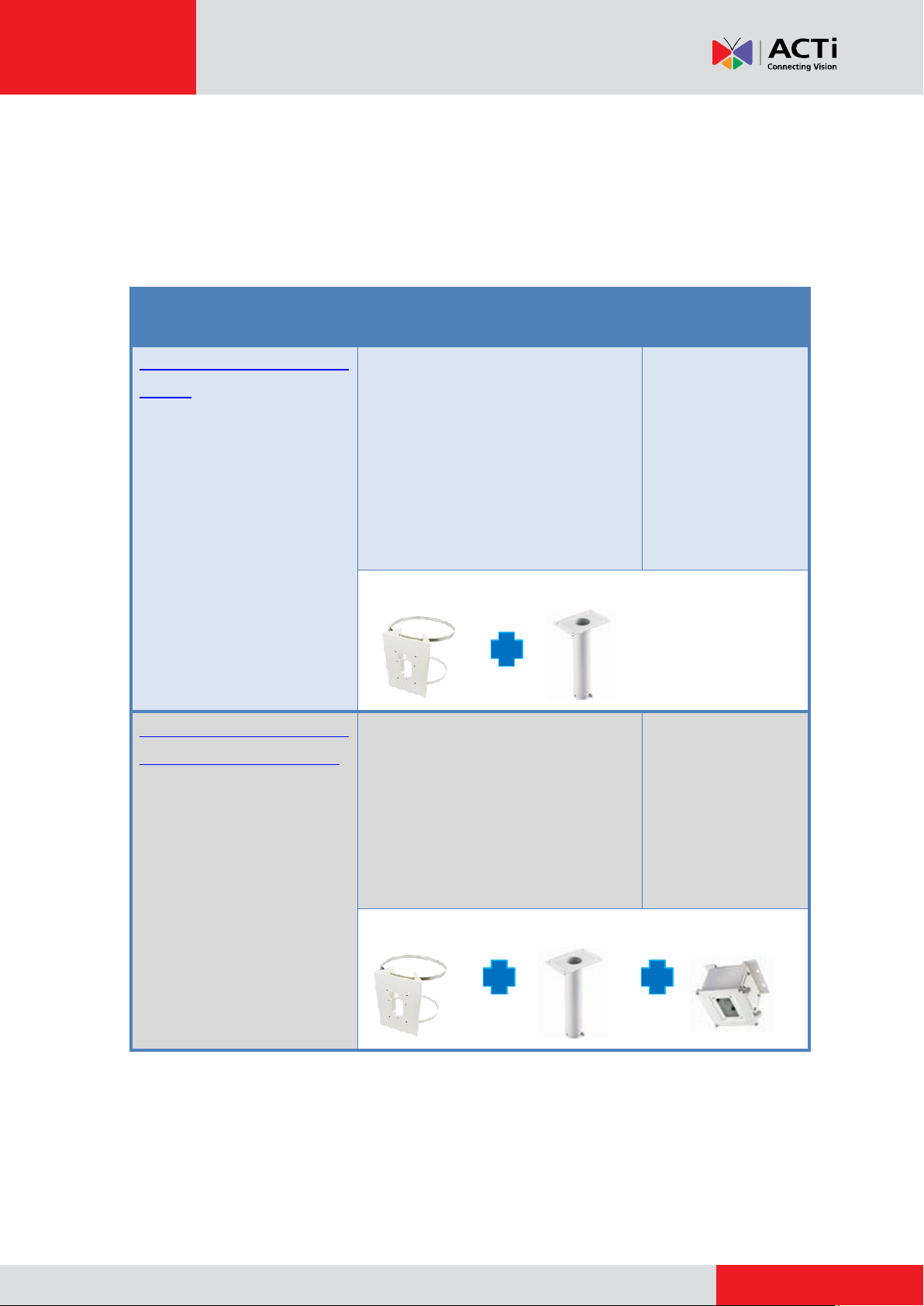
Mounting Solution
Cabling Solution
Must Drill a Hole
on the Wall
Pole Mount with Pendant
Mount
(SMAX-0096)
The cables goes from the top of
the camera into the straight tube
and comes out behind the pole
mount kit.
When using this type of
installation outdoors, it is
recommended to use a high PoE
injector (purchased separately).
No
PMAX- 0503 PMAX-0102
Pole Mount with Pendant
Mount and Junction Box
The cables and the bundled
power adapter are housed inside
the junction box. The cables go
out the junction box enclosed in
a flexible conduit. The flexible
conduit comes out behind the
pole mount kit.
No
PMAX-0503 PMAX-0102 PMAX-0700
Mounting Solutions
If the camera will be installed on a horizontal pole using pendant mount, consider the following
options:
3
Page 4
www.acti.com
Installation Guide
Pole Mount with Pendant Mount
Installation Procedures
The camera body and cables are waterproof. However, when using this type of installation
outdoors, you must take steps to waterproof the cable connections.
The bundled power adapter and power cord, approximately 200 cm in length, are not waterproof
and must be protected indoors. Therefore with this type of installation, it is recommended to use a
high PoE injector (purchased separately) to connect the camera to the power outlet and the
network.
Before installation, prepare the tools and equipment which are not supplied with the mounting
accessory:
Exterior-grade Ethernet Cables
High Power-over-Ethernet (PoE) Injector
Waterproof Tape
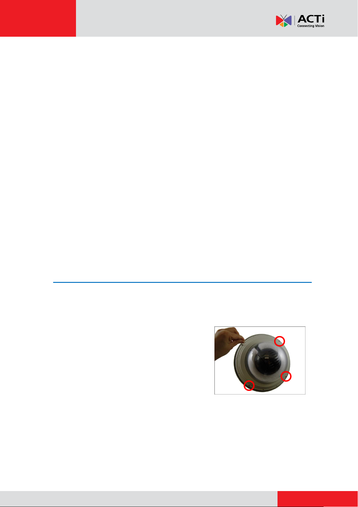
Step 1: Unpack the Camera
NOTE: To avoid scratches or leaving fingerprints on the dome cover, it is recommended to retain
the plastic covering the dome cover until the camera is completely installed.
1. Loosen the four screws using the bundled Allen
wrench.
4
Page 5
www.acti.com
Installation Guide
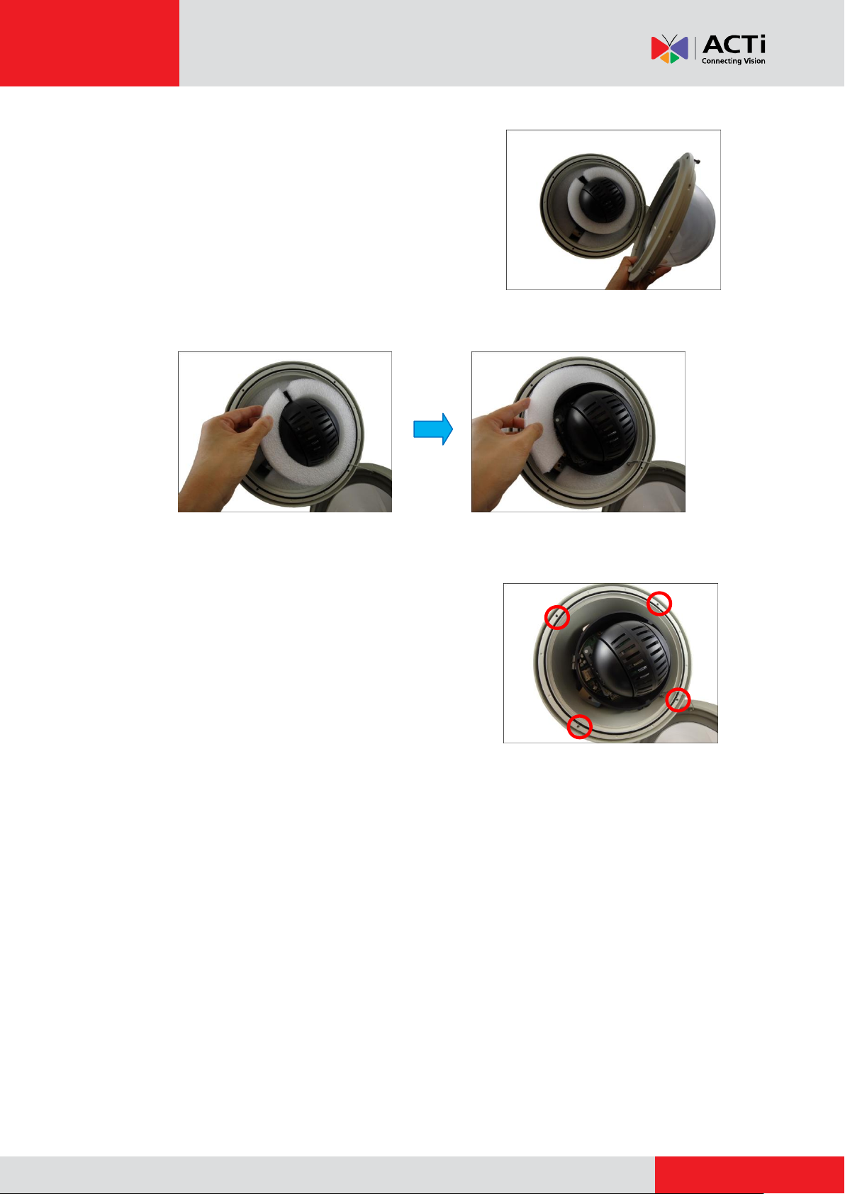
2. Carefully lift the camera cover and place it aside.
NOTE: The cover is attached to the camera by a
metallic wire; do not abruptly lift the cover.
3. Remove the outer and inner Styrofoam.
Outer Styrofoam Inner Styrofoam
4. Attach the camera cover.
Align the cover screws to the screw holes on the
camera (as marked on the illustration) and secure the
screws using the bundled Allen wrench.
5
Page 6
www.acti.com
Installation Guide
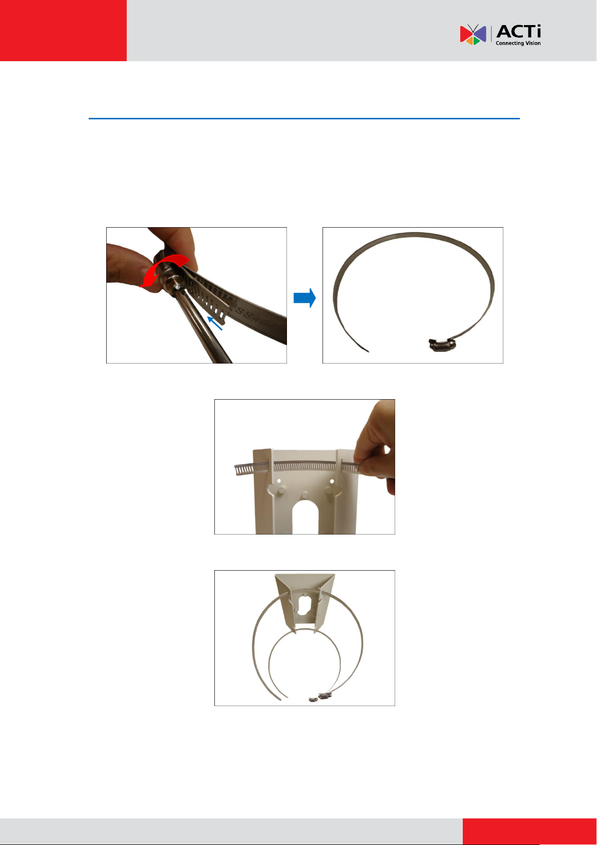
Step 2: Attach the Pole Mount Kit
NOTE: Before installation, make sure the horizontal pole can bear more than the total weight of
the camera and the mounting accessories.
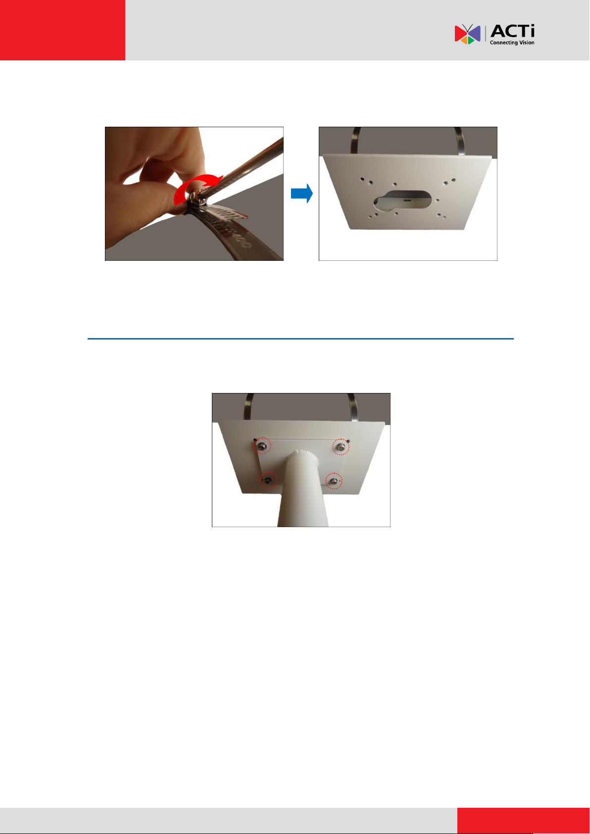
1. Using a screwdriver, turn the screw head of the wire strap counter-clockwise continuously
until the two ends are detached.
2. Insert the wire strap through the strap holes of the pole mount.
3. Do steps 1 and 2 to the other wire strap.
4. Encircle the pole with the wire straps.
NOTE: The wire straps can hold between 134 ~ 228 mm (5.28 ~ 9 in.) pole diameter.
6
Page 7
www.acti.com
Installation Guide
5. Continuously turn the screw head clockwise to adjust the wire strap until it snugly fits the pole.
Do the same to the other wire strap.
Step 3: Install the Straight Tube
Attach the straight tube onto the pole mount using the four (4) screws (included in the Pole Mount
Kit package).
Optional: Add Extension Tube(s)
If the straight tube is not long enough, add one or more extension tubes (purchased separately).
If more than one extension tubes will be used, use extension cables, like network cables (not
included in the package) to extend the length of the pre-installed camera cables. See How to
Install Extension Tubes on page 31.
7
Page 8
www.acti.com
Installation Guide
Step 4: Install the Camera
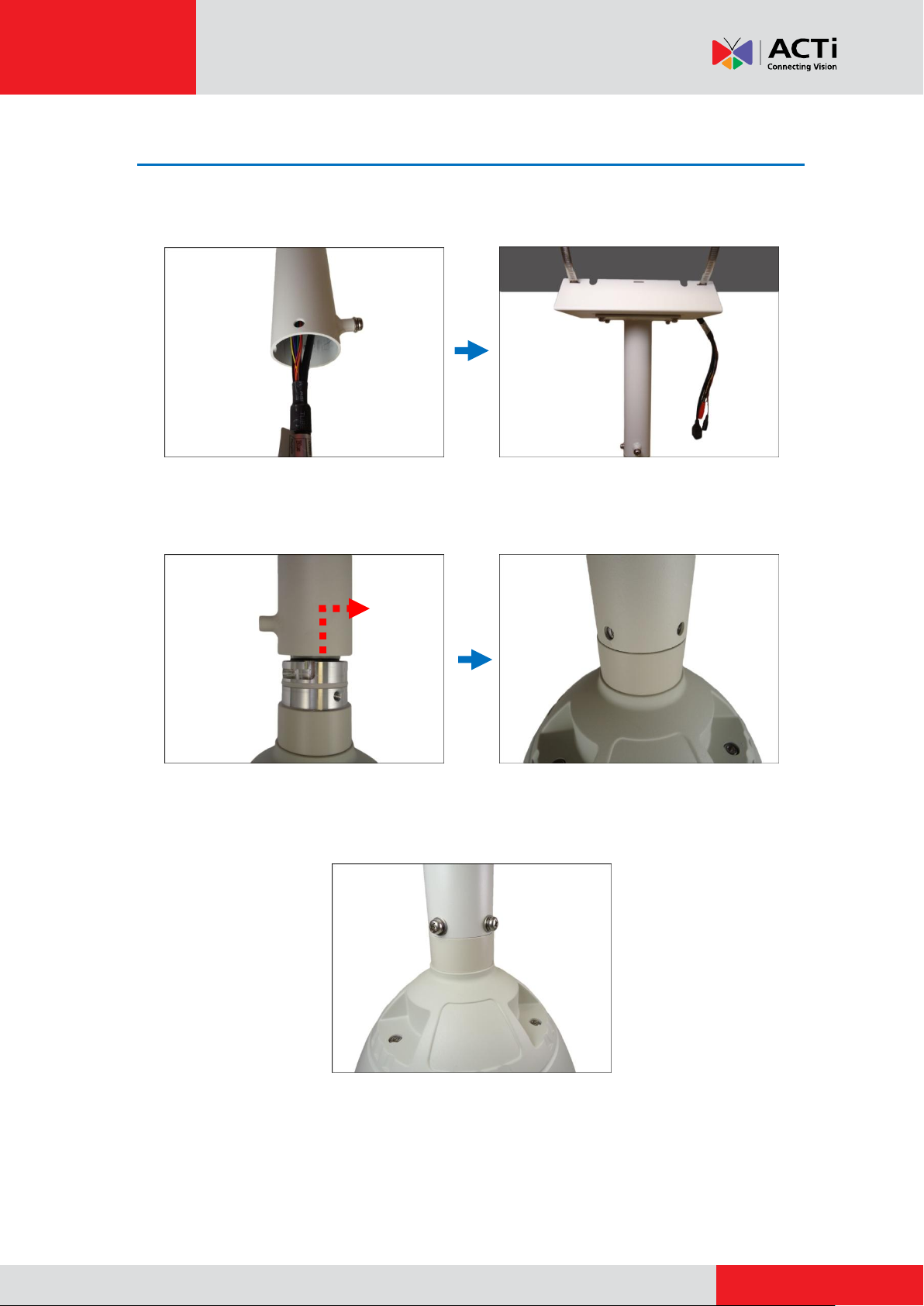
1. Insert the camera cables through the straight tube, extension tube (if any), and through one
the side of the pole mount kit.
2. Align the slot on the camera to the tab inside the straight tube and insert the top of the
camera.
3. Twist the camera to align the screw holes and attach the two (2) mounting screws (included
in the camera package).
4. For I9x models, attach the safety wire strap for added protection; see How to Attach the
Safety Wire Strap (For I9x Models) on page 33.
5. Remove the plastic covering the dome cover.
8
Page 9
www.acti.com
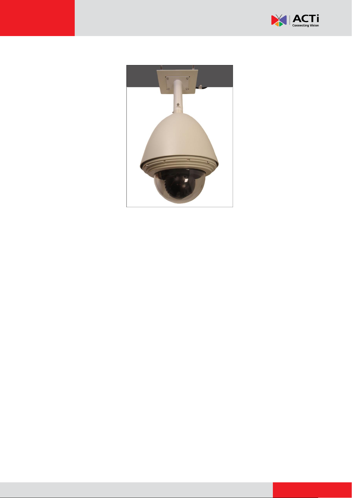
Below is a sample installation.
Installation Guide
9
Page 10
www.acti.com
Installation Guide
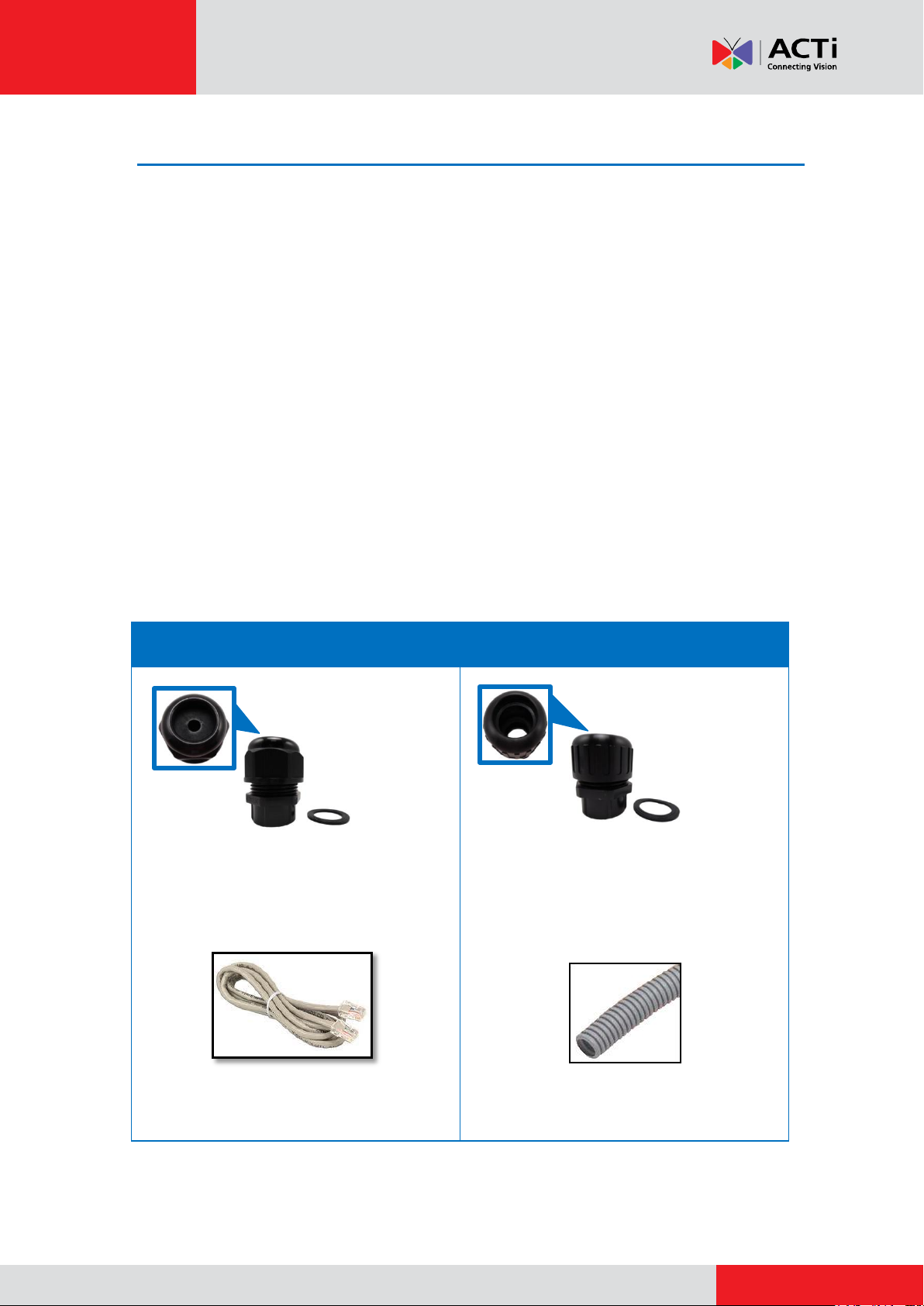
Cable Gland
Conduit Gland
For use with an exterior-grade Ethernet cable
(not included in the package).
See How to Waterproof the Cable Using
the Cable Gland on page 11.
For use with 1/2” flexible conduit (not included
in the package).
See How to Waterproof the Cable Using
the Conduit Gland on page 15.
Step 5: Connect the Cables
The camera itself is waterproof, however take note that the cable connections are not.
If the camera is mounted directly on the wall where the cables pass through the wall, then your
installation is complete and you do not need to waterproof the cable connections.
However, if the camera is mounted where the cables may be exposed then it is recommended to
waterproof the cable connections or use a junction box.
The camera comes with a Cable Gland and Conduit Gland. It is recommended to use one of
these glands when a high PoE injector will be used with the camera. However, if the bundled
power adapter will be used or digital input/output devices will be connected, it is recommended to
house the cables inside the junction box (see Pole Mount with Pendant Mount and Junction
Box Installation Procedures on page 19).
Determine the type of waterproof solution applicable to your installation environment
requirements and prepare the necessary accessories or purchase extra materials.
10
Page 11
www.acti.com
Installation Guide
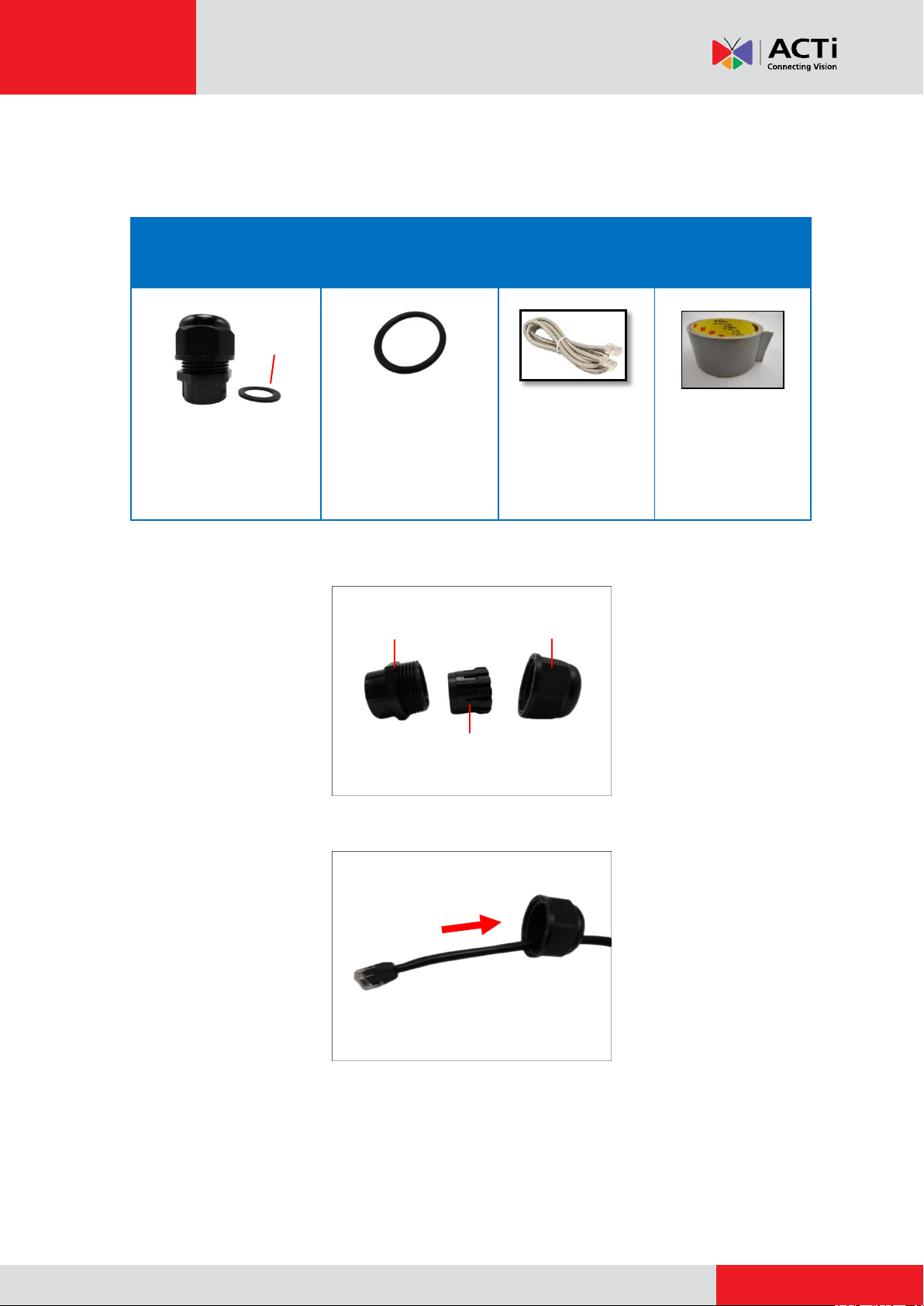
Cable Gland
Gland Rubber Ring
Exterior-Grade
Ethernet Cable
Waterproof Tape
NOTE: The washer will
not be used in this
installation, please set it
aside.
NOTE: Not included
in the camera
package.
NOTE: Not included
in the camera
package.
Gland Body
Clamping Nut
Sealing Rubber and Claw
Washer
How to Waterproof the Cable Using the Cable Gland
1. Prepare the following items:
2. Detach the cable gland as shown below.
3. Insert the clamping nut through the Ethernet cable.
11
Page 12

www.acti.com
Installation Guide
4. Insert the Ethernet cable through the sealing rubber and claw.
5. Attach one (1) supplied rubber ring on the gland body (smooth end).
NOTE: Make sure the rubber ring is completely aligned on the gap on the gland body.
6. Attach the gland body to the Ethernet port of the camera.
IMPORTANT!
Make sure the rubber ring is completely aligned and flat on the gland body to avoid
possible water leakage.
12
Page 13

www.acti.com
Installation Guide
7. Connect the Ethernet connector to the Ethernet port of the camera.
8. Insert the sealing rubber and claw into the cable gland body.
9. Attach the clamping nut to the cable gland body. Make sure the clamping nut is tightly
secured and the rubber is squeezed in to avoid water leakage.
13
Page 14

www.acti.com
Installation Guide
10. If necessary, connect the colored wires to digital input or output (DI/DO) devices to trigger
events or notifications. Make sure to waterproof the cable connection (e.g. wrap with
waterproof tape).
NOTE: Follow the wiring instructions described in the Camera Hardware Manual
downloadable from the website (www.acti.com).
11. Arrange all unused cables and wrap them with the waterproof tape.
NOTE:
Different applications and installation environments require different types of
waterproofing methods which may not be covered in this manual. Check your
installation environment and adapt a suitable waterproofing method.
If the camera is installed outdoors and the bundled power adapter is used or
input/output devices are connected, be sure to protect them from different
environmental factors. It is recommended to place the cable connections indoors or
housed them inside a junction box (see Pole Mount with Pendant Mount and
Junction Box Installation Procedures on page 19).
DISCLAIMER: ACTi will not be responsible for camera damage caused by improper use
of the power adapter.
14
Page 15

www.acti.com
Installation Guide
Cable Gland
Gland Rubber Ring
1/2” Flexible Conduit
Waterproof Tape
NOTE: The washer
will not be used in this
installation, please set
it aside.
NOTE: Not included
in the camera
package.
NOTE: Not included in
the camera package.
Gland Body
Clamping Nut
Sealing Rubber
Washer
How to Waterproof the Cable Using the Conduit Gland
1. Prepare the following items:
2. Detach the conduit gland as shown below.
3. Insert the Ethernet cable through the flexible conduit. Then insert the clamping nut through
the flexible conduit.
15
Page 16

www.acti.com
Installation Guide
4. Insert the sealing rubber and attach it at the end of the flexible conduit.
5. Attach one (1) supplied rubber ring on the gland body (smooth end).
NOTE: Make sure the rubber ring is completely aligned on the gap on the gland body.
6. Attach the gland body to the Ethernet port of the camera.
IMPORTANT!
Make sure the rubber ring is completely aligned and flat on the gland body to avoid
possible water leakage.
16
Page 17

www.acti.com
Installation Guide
7. Connect the Ethernet connector to the Ethernet port of the camera.
8. Insert the sealing rubber into the conduit gland body.
9. Attach the clamping nut to the conduit gland body. Make sure the clamping nut is tightly
secured to avoid water leakage.
17
Page 18

www.acti.com
Installation Guide
10. If necessary, connect the colored wires to digital input or output (DI/DO) devices to trigger
events or notifications.
NOTE: Follow the wiring instructions described in the Camera Hardware Manual
downloadable from the website (www.acti.com).
11. Arrange all unused cables and wrap them with the waterproof tape.
NOTE:
Different applications and installation environments require different types of
waterproofing methods which may not be covered in this manual. Check your
installation environment and adapt a suitable waterproofing method.
If the camera is installed outdoors and the bundled power adapter is used or
input/output devices are connected, be sure to protect them from different
environmental factors. It is recommended to place the cable connections indoors or
housed them inside a junction box (see Pole Mount with Pendant Mount and
Junction Box Installation Procedures on page 19).
DISCLAIMER: ACTi will not be responsible for camera damage caused by improper use
of the power adapter.
18
Page 19

www.acti.com
Installation Guide
Gland
3/4" Size
Flexible Conduit
3/4" Size
Sealing
insert
Clamping Nut
Pole Mount with Pendant Mount and
Junction Box Installation Procedures
Perform the following procedures to install the camera on a horizontal pole using pendant mount
with a junction box.
This type of installation is ideal when using the bundled power adapter and power cord to ensure
they are protected from different types of weather conditions.
Before installation, prepare the tools and equipment which are not supplied with the mounting
accessories:
Ethernet Cables
Flexible Conduit with Conduit Gland (Size 3/4”)
NOTE: Below is an example of a common conduit gland with flexible conduit available in
the market. Actual items sold in your area may vary.
For use with the bundled power adapter and power cord, prepare also the following equipment:
Female-type Socket
Male-type Plug
Power Cable without connectors (length depends on the distance of the power supply
outlet and installation site)
Electrical tape
19
Page 20

www.acti.com
Installation Guide
Step 1: Unpack the Camera
NOTE: To avoid scratches or leaving fingerprints on the dome cover, it is recommended to retain
the plastic covering the dome cover until the camera is completely installed.
1. Loosen the four screws using the bundled Allen
wrench.
2. Carefully lift the camera cover and place it aside.
NOTE: The cover is attached to the camera by a
metallic wire; do not abruptly lift the cover.
3. Remove the outer and inner Styrofoam.
Outer Styrofoam Inner Styrofoam
20
Page 21

www.acti.com
Installation Guide
4. Attach the camera cover.
Align the cover screws to the screw holes on the
camera (as marked on the illustration) and secure the
screws using the bundled Allen wrench.
Step 2: Prepare the Junction Box
1. Remove the four (4) screws securing the bracket from the juction box.
NOTE:
The bracket is not necessary for this installation, please keep it aside.
Retain the four (4) screws to be used in installing the pole mount later.
2. Remove one or two of the rear metal cap(s) as needed.
21
Page 22

www.acti.com
Installation Guide
Conduit Gland Body:
Attach to the Junction Box
3. Remove the four (4) screws securing the side door.
Step 3: Prepare for Waterproof Installation
1. Prepare the flexible conduit with conduit gland (size 3/4").
2. Insert the cables, such as the network cable, power cable without connectors (if using the
bundled power adapter and power cord), etc., through the flex conduit.
NOTE: Only a power cable fits through the conduit hole of the junction box; thus the
installation of a power outlet to the power cable must be done inside the junction box.
3. Attach the conduit gland body to one of the rear side holes of the junction box.
22
Page 23

www.acti.com
Installation Guide
Step 4: Prepare the Pole Mount Kit
NOTE: Before installation, make sure that the ceiling can bear more than the total weight of the
camera and the mounting accessories.
1. Align the screw holes of the pole mount and the junction box.
2. Attach the four (4) screws, which were removed from the junction box bracket, to secure the
pole mount to the junction box.
3. Insert enough length of the cables into the junction box and attach the clamping nut to the
conduit gland body.
CAUTION: Make sure the clamping nut is securely attached to the conduit gland body
to avoid water leak, etc.
23
Page 24

www.acti.com
Installation Guide
DISCLAIMER: The manufacturer will not be responsible for damage caused by water leak
from incorrect cabling methods.
4. Using a screwdriver, turn the screw head of the pole mount wire strap counter-clockwise
continuously until the two ends are detached.
5. Insert the wire strap through the strap holes of the pole mount.
6. Do steps 4 and 5 to the other wire strap.
7. Encircle the pole with the wire straps.
NOTE: The wire straps can hold between 134 ~ 228 mm (5.28 ~ 9 in.) pole diameter.
24
Page 25

www.acti.com
Installation Guide
8. Continuously turn the screw head clockwise to adjust the wire strap until it snugly fits the pole.
Do the same to the other wire strap.
25
Page 26

www.acti.com
Installation Guide
Step 5: Install the Straight Tube
Attach the straight tube onto the pole mount using the four (4) screws (included in the Pole Mount
Kit package).
Optional: Add Extension Tube(s)
If the straight tube is not long enough, add one or more extension tubes (purchased separately).
If more than one extension tubes will be used, use extension cables, like network cables (not
included in the package) to extend the length of the pre-installed camera cables. See How to
Install Extension Tubes on page 31.
26
Page 27

www.acti.com
Installation Guide
Step 6: Install the Camera
1. Insert the camera cables through the straight tube, extension tube (if any), and into the
junction box.
2. Align the slot on the camera to the tab inside the straight tube and insert the top of the
camera.
3. Twist the camera to align the screw holes and attach the two (2) mounting screws (included
in the camera package).
4. For I9x models, attach the safety wire strap for added protection; see How to Attach the
Safety Wire Strap (For I9x Models) on page 33.
5. Remove the plastic covering the dome cover.
27
Page 28

www.acti.com
Below is a sample installation.
Installation Guide
28
Page 29

www.acti.com
Installation Guide
Step 7: Connect the Cables
From the junction box, perform the following:
1. Connect the bundled power adapter and power cord and place them inside the junction box.
For I9x models, see How to Use the Power Adapter (For I9x Models) on page 32 for more
information on using the power adapter.
2. Connect the Ethernet cable from the network side to the Ethernet port of the camera.
3. If necessary, connect the colored wires to digital input or output (DI/DO) devices to trigger
events or notifications.
NOTE: Follow the wiring instructions described in the Camera Hardware Manual
downloadable from the website (www.acti.com).
4. Attach the female-type socket to the power cable in the junction box, and connect the power
cord to the socket.
NOTE:
Only a power cable fits through the conduit hole of the junction box; thus the
installation of a power outlet to the power line cable must be done inside the junction
box.
Use only the supplied power adapter and power cord that came with the camera or
the optional High PoE Injector (PPOE-0110). Using other accessories not approved
by the manufacturer may cause damage to the equipment.
29
Page 30

www.acti.com
Installation Guide
5. Close the junction box door using the four (4) screws supplied with the junction box.
6. NOTE: Make sure the side is door is tightly sealed to ensure water does not enter the
junction box.
7. On the network side, connect the other end of the Ethernet cable to a network switch.
8. On the power supply side, attach the male-type plug on the other end of the power cable, and
then connect it to a power outlet.
30
Page 31

www.acti.com
Installation Guide
Appendices
How to Install Extension Tubes
If the Straight Tube is not long enough, add one or more extension tubes (purchased separately).
1. Remove the two (2) pre-installed screws on the extension tube.
2. Insert the cable into the extension tube.
3. Align the slot on the extension tube to the tab inside the Straight Tube and install the
extension tube.
4. Twist the extension tube to align the screw holes and reattach the two (2) mounting screws
removed from step 1.
31
Page 32

www.acti.com
Installation Guide
1
2
Camera Side
Power Adapter
Side
How to Use the Power Adapter (For I9x Models)
1. Slide the voltage switch to set the adapter voltage according to the voltage standard in your
location.
2. Connect the power cord to the power adapter.
3. Connect the power connector of the camera to the cable connector of the adapter.
32
Page 33

www.acti.com
Installation Guide
How to Attach the Safety Wire Strap (For I9x Models)
Most of ACTi’s mounting accessories have a safety screw where the bundled safety wire strap
can be used as additional protection to avoid dropping the camera while mounted on the high
ceilings, etc.
To attach the safety wire strap, do the following:
1. Using a screwdriver, remove the screw on top of the camera.
2. Insert the screw through the smaller end of the safety wire strap and attach it to the camera.
3. Remove the safety screw from the mounting solution (below is an example of the straight
tube).
33
Page 34

www.acti.com
Installation Guide
4. Align the bigger end of the safety wire strap on the mounting solution and then tightly attach
the screw to lock the safety wire strap in place.
34
Page 35

www.acti.com
Installation Guide
Safety Information
Read these instructions
You should read all the safety and operating instructions before using this product.
Heed all warnings
You must adhere to all the warnings on the product and in the instruction manual. Failure to follow
the safety instruction given may directly endanger people, cause damage to the system or to
other equipment.
Trademarks
All names used in this manual are probably registered trademarks of respective companies.
Liability
Every reasonable care has been taken during the writing of this manual. Please inform your local
office if you find any inaccuracies or omissions. We cannot be held responsible for any
typographical or technical errors and reserve the right to make changes to the product and
manuals without prior notice.
Cleaning
Disconnect this video product from the power supply before cleaning.
Attachments
Do not use attachments not recommended by the video product manufacturer as they may cause
hazards.
Do not use accessories not recommended by the manufacturer
Only install this device in a dry place protected from weather
Servicing
Do not attempt to service this video product yourself. Refer all servicing to qualified service
personnel.
35
Page 36

www.acti.com
Installation Guide
Damage Requiring service
Disconnect this video product from the power supply immediately and refer servicing to qualified
service personnel under the following conditions.
1) When the power-supply cord or plug is damaged
2) If liquid has been spilled, or objects have fallen into the video product.
3) If the inner parts of video product have been directly exposed to rain or water.
4) If the video product does not operate normally by following the operating Instructions in this
manual. Adjust only those controls that are covered by the instruction manual, as an improper
adjustment of other controls may result in damage, and will often require extensive work by a
qualified technician to restore the video product to its normal operation.
Safety Check
Upon completion of any service or repairs to this video product, ask the service technician to
perform safety checks to determine if the video product is in proper operating condition.
36
 Loading...