

ACTi Outdoor Mini PTZ Dome Installation Guide on Dropped Ceiling

2014/01/09
Outdoor Mini PTZ
Mounting on the Ceiling
with Flat Surface
(Face Down)
Installation Guide
For Models:
B94, B95, B96, B97

www.acti.com
Installation Guide
Table of Contents
Installation Procedures ..................................................... 3
Step 1: Drill the Holes ................................................................................ 3
Step 2: Open the Dome Cover .................................................................. 4
Step 3: Prepare for Waterproof and Connect the Cable ......................... 6
Waterproof Solution with Naked Cable ................................................... 7
Waterproof Solution with Conduit .......................................................... 10
Step 4: Install the Camera to the Surface .............................................. 15
Step 5: Close the Dome Cover ................................................................ 15
Step 6: Connect to the Network .............................................................. 16
Step 7: Access the Camera Live View .................................................... 16
Appendices ....................................................................... 17
How to Remove / Install the Camera Module......................................... 17
How to Remove the Camera Module .................................................... 17
How to Install the Camera Module ........................................................ 18
How to Insert / Remove a Memory Card ................................................ 19
How to Insert the Memory Card ............................................................ 19
How to Remove the Memory Card ........................................................ 19
How to Connect a Power Adapter (Optional) ........................................ 20
How to Connect DI/DO and Audio Devices (Optional) .......................... 22
How to Connect DI/DO Devices ............................................................ 22
How to Connect Audio Devices ............................................................. 25
Safety Information ............................................................ 26
2
www.acti.com
Installation Guide
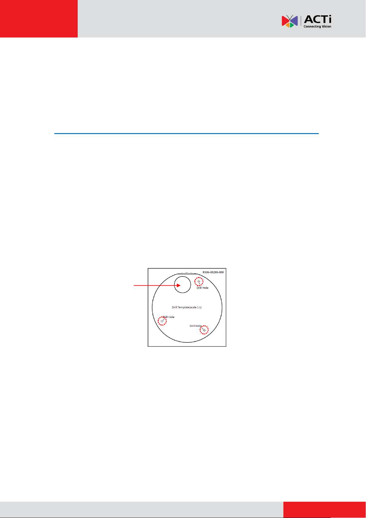
Cable hole
Installation Procedures
This section describes the procedures in installing the camera on a flat surface such as the
ceiling. Before installation, make sure the ceiling can bear more than the weight of the camera.
Step 1: Drill the Holes
Before drilling the holes on the ceiling, note the direction of the connectors side of the camera,
which is also the opposite side of the camera logo. This influences the camera placement and
where you should drill the hole where the cables will pass through or how the cables will go along
the ceiling.
1. Attach the supplied drill template on the surface according to the preferred camera
orientation.
2. Determine how the cables will be routed: pass through the surface or along the surface.
If the cables will pass through the surface, drill the cable hole and the three (3)
screw holes on the surface.
If the cables will be routed along the surface, just drill the three (3) screw holes on
the surface.
3. Detach the drill template from the surface and insert the plastic plugs into the screw holes.
3
www.acti.com
Installation Guide
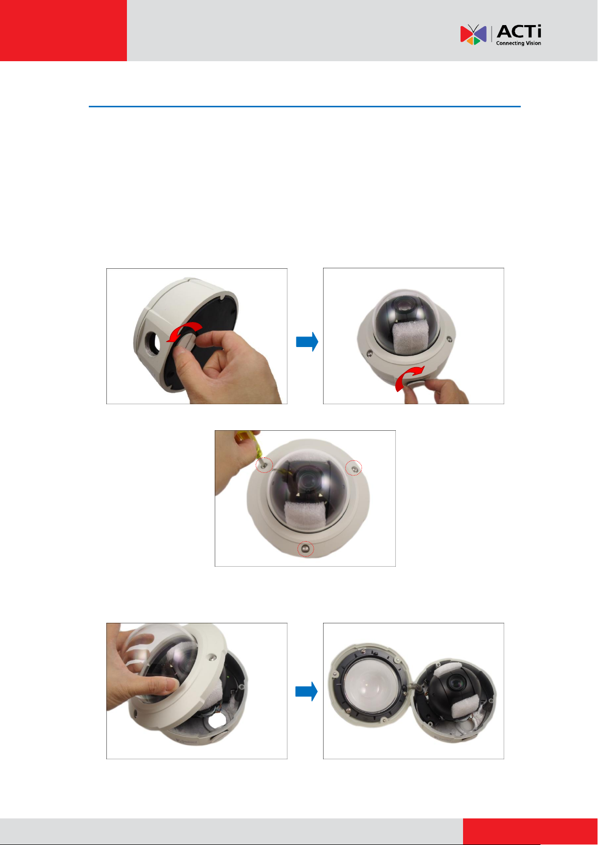
Step 2: Open the Dome Cover
NOTE: To avoid scratches or leaving fingerprints on the dome cover, it is recommended to retain
the plastic covering the dome cover until the camera is completely installed. However, the plastic
has been removed on some of the pictures in this documentation to show clarity of the
procedures being described.
1. If the cables will pass through the surface, remove the metal cap covering the bottom hole
of the camera, and attach the cap to the side hole to close it. The cables will be routed to
pass this hole from the surface.
2. With the bundled hex screwdriver, loosen the three (3) screws securing the dome cover.
3. Carefully lift to open the dome cover and place it on the side of the camera.
NOTE: Do not abruptly lift the dome cover; it is attached to the camera with a spring wire.
4

www.acti.com
Installation Guide
4. Remove the Styrofoam protecting the camera.
5
www.acti.com
Installation Guide
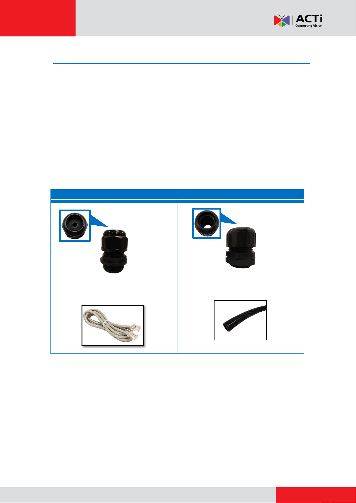
Cable Gland
Conduit Gland
For use with an Exterior-grade Ethernet
cable (not included in the package).
For use with 1/2” flexible conduit (not included
in the package)
Step 3: Prepare for Waterproof and Connect the Cable
The camera comes with two (2) glands used for waterproof installation:
Cable Gland: For use with an Exterior-grade Ethernet cable. Exterior-grade Ethernet
cables are already waterproof. See Waterproof Solution with Naked Cable on page 7.
Conduit Gland: For use with a flexible conduit. This solution is recommended when an
exterior-grade Ethernet cable is not available or other cables, such as power adapter,
DI/DO devices, etc., will be connected to the camera. See Waterproof Solution with
Conduit on page 10.
Determine the type of waterproof solution that is applicable to your installation requirements and
prepare the necessary accessories or purchase extra materials.
6
www.acti.com
Installation Guide
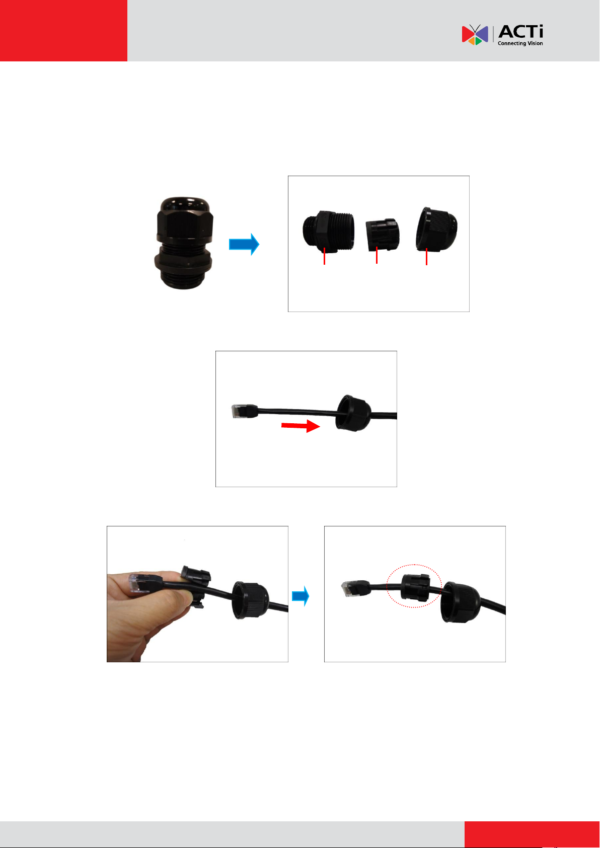
Body
(with Washer)
Sealing Insert
with Claw
Clamping
Nut
Waterproof Solution with Naked Cable
This section describes the procedures in using the bundled cable gland and an exterior-grade
Ethernet cable.
1. Disassemble the cable gland as shown below:
2. Insert the clamping nut into the Ethernet cable.
3. Insert the sealing insert with claw.
7
www.acti.com
Installation Guide
or
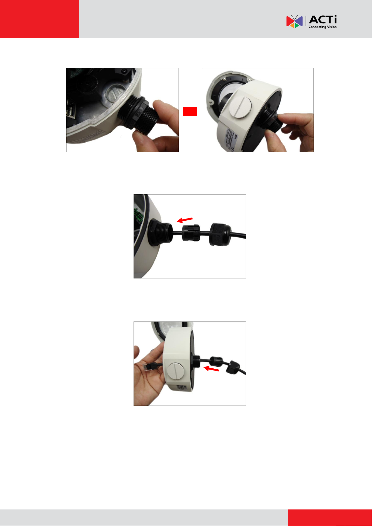
4. Attach the cable gland body to the hole of the camera.
Attach to Camera Side Hole Attach to Camera Bottom Hole
5. If the cable will be routed along the surface, pull the network cable through the side
conduit hole.
If the cable will pass through the surface, pull the network cable through the bottom
conduit hole.
8
www.acti.com
Installation Guide
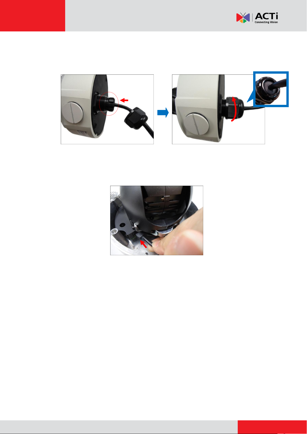
6. Insert the sealing insert with claw into the cable gland body and then attach the clamping nut
to complete the cable solution. Same procedures apply to cable passing the surface or along
the surface.
NOTE: Make sure the clamping nut is tightly attached to the cable gland body and the sealing
insert is squeezed tightly.
7. Connect the network cable to the Ethernet port of the camera.
8. In case a memory card will be used for local recording, see How to Insert the Memory Card
on page 19 and follow the procedures to install a memory card. Otherwise, skip this step.
9. Proceed with Step 4: Install the Camera to the Surface on page 15.
9
 Loading...