

Page 1

2013/12/03
Outdoor Hemispheric
Mounting on a Vertical Pole
Using the Tilted Mount
Installation Guide
For Models:
KCM-7911
Page 2

www.acti.com
Installation Guide
Table of Contents
Mounting Solutions ............................................................ 3
Installation Procedures using Naked Cable .................... 4
Step 1: Attach the Pole Mount Kit ............................................................ 4
Step 2: Attach the Tilted Mount ................................................................ 6
Step 3: Prepare for Waterproof Installation ............................................. 6
Step 4: Open the Camera Cover ............................................................... 8
Step 5: Connect the Cable(s) .................................................................... 9
Step 6: Install the Camera to the Tilted Mount ...................................... 10
Step 7: Close the Cover ........................................................................... 11
Step 8: Access the Camera Live View ..................................................... 11
Installation Procedures using Flex Conduit .................. 12
Step 1: Attach the Pole Mount Kit .......................................................... 12
Step 2: Attach the Tilted Mount .............................................................. 14
Step 3: Open the Camera Cover ............................................................. 14
Step 4: Prepare for Waterproof Installation ........................................... 15
Step 5: Install the Camera to the Tilted Mount ...................................... 19
Step 6: Close the Cover .......................................................................... 19
Step 7: Access the Camera Live View .................................................... 19
Appendices ....................................................................... 20
Connecting a Power Adaptor (Optional) ................................................ 20
Connecting DI/DO Devices (Optional) .................................................... 22
Connecting Audio In / Out Devices (Optional) ...................................... 25
Safety Information ............................................................ 26
2
Page 3
www.acti.com
Installation Guide
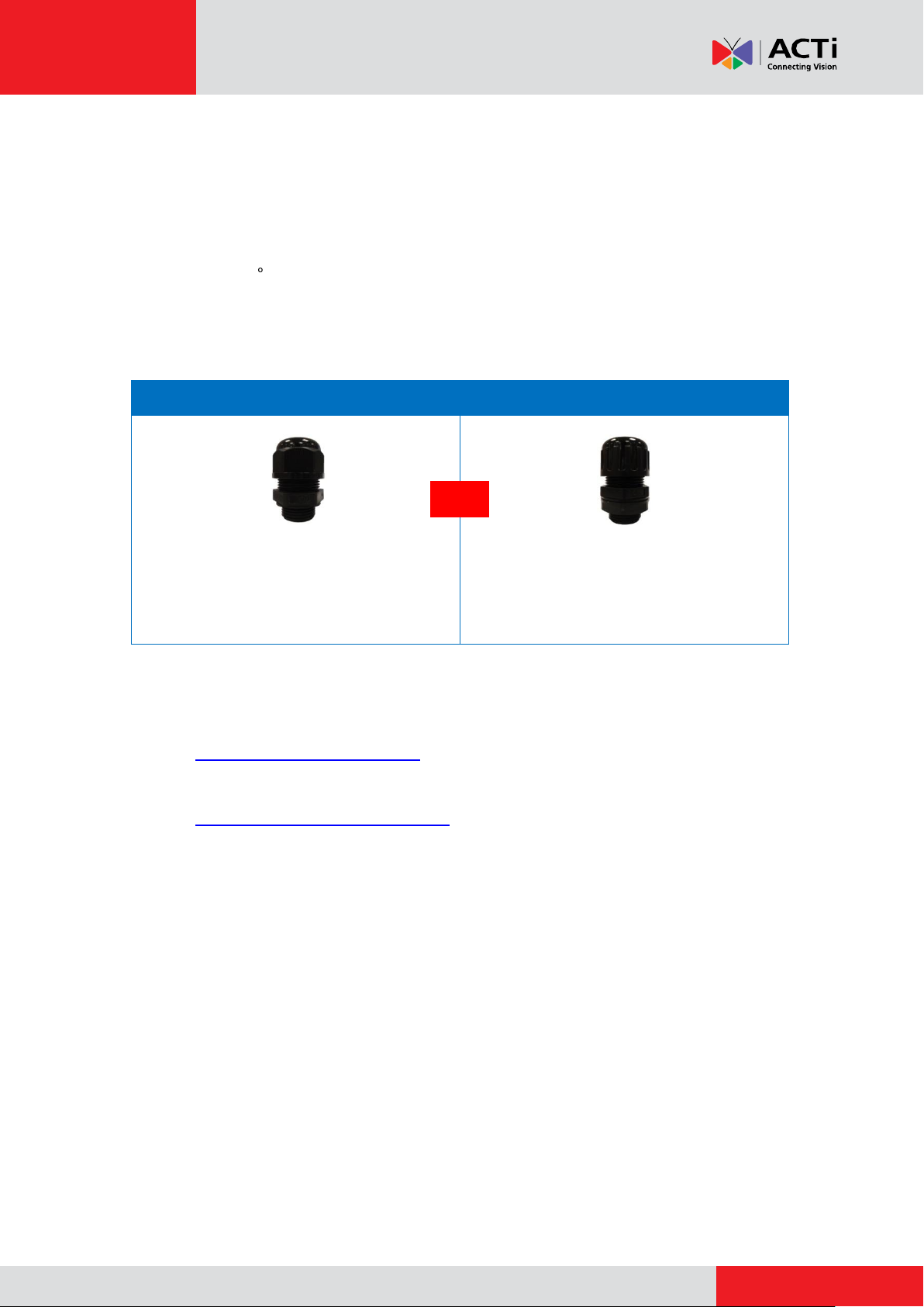
Cable Gland
Conduit Gland
For use with an EXTERIOR-GRADE
Ethernet cable. Exterior-grade Ethernet
cables are already waterproof.
For use with 3/8” flexible conduit.
Recommended when an exterior-grade
Ethernet cable is not available or when other
input/output devices or an external power
adaptor will be connected to the camera.
and
Mounting Solutions
The camera can be mounted on a vertical pole with the camera facing forward using the Pole
Mount with Surface Mount (SMAX-0136). With this accessory combination, the camera faces
forward with a 10 tilt.
The camera comes with two (2) glands used for waterproof installation: Cable gland and Conduit
Gland.
Determine the type of waterproof solution that is applicable to your installation requirements and
prepare the necessary accessories or purchase extra materials.
Installation using Naked Cable: This installation uses the supplied cable gland and an
exterior-grade Ethernet cable (not supplied).
Installation Using Flexible Conduit: This installation uses the supplied conduit gland
and a 3/8” flexible conduit (not supplied). This is the recommended solution if other
input / output devices or an external power adaptor will be connected to the camera.
3
Page 4
www.acti.com
Installation Guide
Installation Procedures using Naked
Cable
This section provides step-by-step procedures in installing the camera on a vertical pole using
the tilted mount and how to waterproof the cabling connection using a naked Ethernet cable.
Before installation, prepare the following tools and accessories which are not included in the
camera package, thus must be purchased separately:
Pole Mount with Surface Mount (SMAX-0136)
Exterior-grade Ethernet Cable
Step 1: Attach the Pole Mount Kit
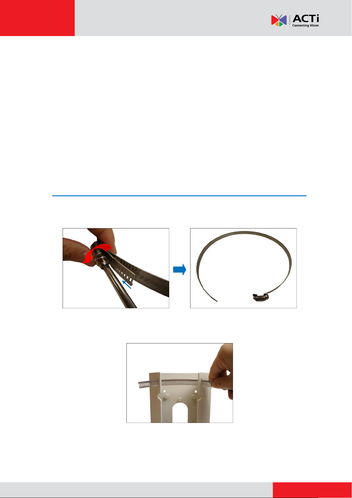
1. Using a screwdriver, turn the screw head of the wire strap counter-clockwise continuously
until the two ends are detached.
2. Insert the wire strap through the strap holes of the pole mount.
4
Page 5

www.acti.com
Installation Guide
This side up
3. Do steps 1 and 2 to the other wire strap.
4. Position the pole mount with the cable path up and encircle the pole with the wire straps.
NOTE: The wire straps can hold between 134 ~ 228 mm (5.28 ~ 9 in.) pole diameter.
5. Continuously turn the screw head clockwise to adjust the wire strap until it snugly fits the pole.
Do the same to the other wire strap.
5
Page 6
www.acti.com
Installation Guide
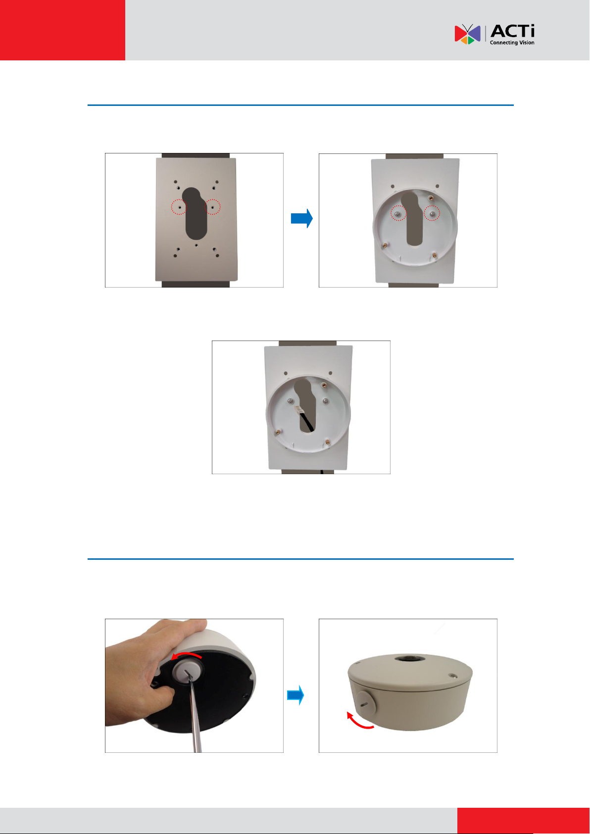
Step 2: Attach the Tilted Mount
1. Attach two (2) screws (included in the pole mount package) to secure the tilted mount to the
pole mount.
2. From the network side, route the Ethernet cable along the pole to pass through the hole on
pole mount and tilted mount.
Step 3: Prepare for Waterproof Installation
1. Remove the cap covering the bottom hole of the camera, and attach the cap to the side hole
to close it. The network cable will pass through the bottom hole.
6
Page 7
www.acti.com
Installation Guide
Body
(with Washer)
Sealing Insert
with Claw
Clamping
Nut
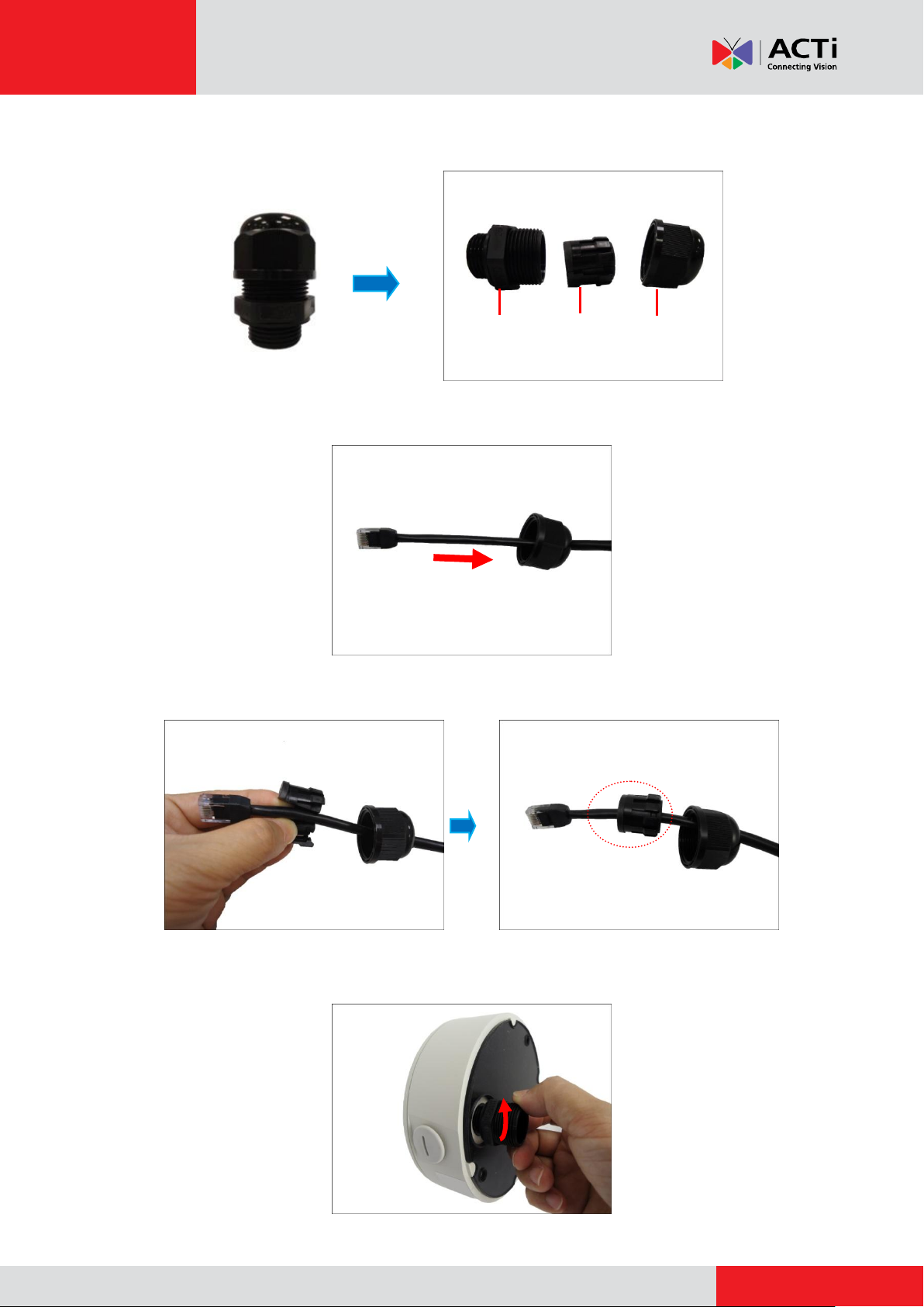
2. Disassemble the cable gland as shown below:
3. Insert the clamping nut into the Ethernet cable of the camera side.
4. Insert the sealing insert with claw.
5. Attach the cable gland body to the hole of the camera.
7
Page 8
www.acti.com
Installation Guide
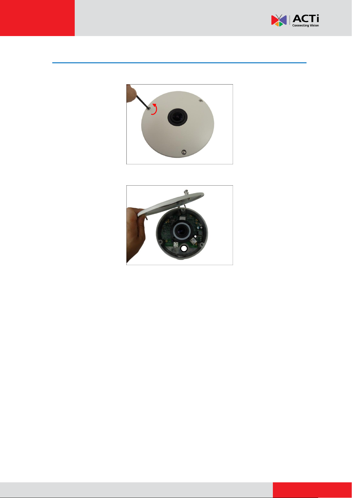
Step 4: Open the Camera Cover
1. Loosen the three (3) screws using the supplied hex wrench.
2. Lift to open the cover.
NOTE: Do not abruptly lift the cover; it is attached to the camera body with a spring wire.
8
Page 9
www.acti.com
Installation Guide
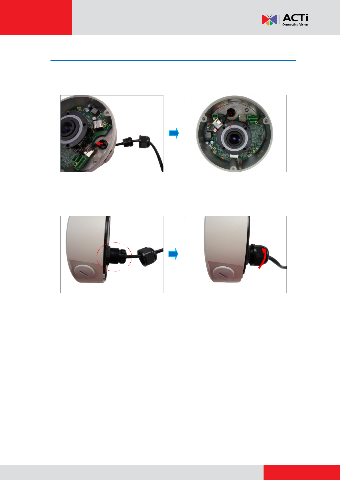
Step 5: Connect the Cable(s)
1. Insert the Ethernet cable through the cable gland body and connect it to the Ethernet port of
the camera.
2. Insert the sealing insert with claw into the cable gland body and then attach the clamping nut
to complete the cable solution.
NOTE: Make sure the clamping nut is tightly attached to the cable gland body.
9
Page 10

www.acti.com
Installation Guide
Rubber Ring
Step 6: Install the Camera to the Tilted Mount
1. If necessary, insert a memory card into the card slot of the camera.
2. Align the camera to the tilted mount as the cable is pushed through the cable hole on the
tilted mount and pole mount.
3. Attach the camera to the tilted mount using the three (3) screws supplied in the Tilted Mount
package.
NOTE: Make sure the tilted mount screws have rubber rings. If the screws you received do
not have rubber rings, please contact your local sales agents or our Customer Help Desk
(CHD) for support.
10
Page 11

www.acti.com
Installation Guide
Step 7: Close the Cover
Tighten the three (3) screws to secure the cover.
Step 8: Access the Camera Live View
For information on how to access the camera Live View, download the camera Hardware Manual
from the website (http://www.acti.com).
11
Page 12

www.acti.com
Installation Guide
Installation Procedures using Flex
Conduit
This section provides step-by-step procedures in installing the camera on a vertical pole using
the tilted mount and how to waterproof the cabling connection using a flexible conduit. with 3/8”
trade size (not supplied). This is the recommended solution when connecting an external power
adaptor, audio in/out, or digital input/output (DI/DO) devices to the camera.
Before installation, prepare the following tools and accessories which are not included in the
camera package, thus must be purchased separately:
Pole Mount with Surface Mount (SMAX-0136)
Flexible Conduit (Trade size = 1/2”)
Ethernet Cable
Step 1: Attach the Pole Mount Kit
1. Using a screwdriver, turn the screw head of the wire strap counter-clockwise continuously
until the two ends are detached.
2. Insert the wire strap through the strap holes of the pole mount.
12
Page 13

www.acti.com
Installation Guide
This side up
3. Do steps 1 and 2 to the other wire strap.
4. Position the pole mount with the cable path up and encircle the pole with the wire straps.
NOTE: The wire straps can hold between 134 ~ 228 mm (5.28 ~ 9 in.) pole diameter.
5. Continuously turn the screw head clockwise to adjust the wire strap until it snugly fits the pole.
Do the same to the other wire strap.
13
Page 14

www.acti.com
Installation Guide
Step 2: Attach the Tilted Mount
Attach two (2) screws (included in the pole mount package) to secure the tilted mount to the pole
mount.
Step 3: Open the Camera Cover
1. Remove the cap covering the bottom hole of the camera, and attach the cap to the side hole
to close it. The network cable will pass through the bottom hole.
2. Loosen the three (3) screws using the supplied hex wrench.
14
Page 15

www.acti.com
Installation Guide
Lock
Nut
Body
(with Washer)
Sealing
Rubber
Clamping
Nut
3. Lift to open the cover.
NOTE: Do not abruptly lift the cover; it is attached to the camera body with a spring wire.
Step 4: Prepare for Waterproof Installation
1. Disassemble the cable gland as shown below:
2. Pull the Ethernet cable and other cables (if any) through the flex conduit.
NOTE: To connect an external power adaptor, audio in/out, or digital input/output (DI/DO)
devices, insert the cables without connectors through the flex conduit together with the
Ethernet cable at this point.
15
Page 16

www.acti.com
Installation Guide
3. From the network side, route the flex conduit to pass through the pole mount and tilted
mount.
4. Insert the clamping nut through the flex conduit.
5. Insert the sealing rubber and attach it at the end of the flex conduit.
6. Attach the conduit gland body to the hole of the camera.
16
Page 17

www.acti.com
Installation Guide
or
12V Power Connector
Digital Input / Output
(DI/DO) Connector
Audio Input / Output
Connector
or
7. Attach the lock nut to secure the conduit gland body to the camera.
8. Insert the Ethernet cable and other cables (if any) through the conduit gland body.
Ethernet Only Ethernet and External Power Adaptor Cable
9. Connect the Ethernet cable to the Ethernet port of the camera. If connecting other cables,
such as an external power adaptor, audio in/out or DI/DO devices, connect the terminal
blocks at this point and connect them to the corresponding connectors of the camera (see
Appendices on page 20 for more information).
17
Page 18

www.acti.com
Installation Guide
10. Insert the sealing rubber into the conduit gland body and attach the clamping nut to complete
the cable solution.
NOTE: Make sure the clamping nut is tightly attached to the conduit gland body.
11. Align the camera to the tilted mount as the flex conduit is pushed through the cable hole of
the tilted mount and pole mount.
18
Page 19

www.acti.com
Installation Guide
Rubber Ring
Step 5: Install the Camera to the Tilted Mount
1. If necessary, insert a memory card into the card slot of the camera.
2. Attach the camera to the tilted mount using the three (3) screws supplied in the Tilted Mount
package.
NOTE: Make sure the tilted mount screws have rubber rings. If the screws you received do
not have rubber rings, please contact your local sales agents or our Customer Help Desk
(CHD) for support.
Step 6: Close the Cover
Tighten the three (3) screws to secure the cover.
Step 7: Access the Camera Live View
For information on how to access the camera Live View, download the camera Hardware Manual
from the website (http://www.acti.com).
19
Page 20

www.acti.com
Installation Guide
White stripe: Connects to 12V Pin
Connects to GND Pin
Appendices
This section describes the procedures in preparing the external devices that you can connect to
the camera. The camera supports DC12V power input, Digital Input and Output (DI/DO) and
Audio Input and Output devices using the bundled terminal blocks. The use of these devices,
however, is optional.
Connecting a Power Adaptor (Optional)
The camera consumes 9.6W power when powered by a Power over Ethernet (PoE) switch that is
IEEE802.3af compliant. In case of using a non-PoE switch or your PoE switch has limited power
supply, you can purchase a power adaptor and directly connect the camera to a power outlet. The
power adaptor must be connected to the supplied terminal block before use.
To do this, follow the procedures below:
1. Loosen the screws of the 12V and GND pins of the power terminal block.
2. Take note that a standard power adaptor cable has two (2) different wires:
20
Page 21

www.acti.com
Installation Guide
3. Connect the wire with the white stripe to the 12V pin and the other to the GND pin.
4. Tighten the screws of the 12V pin and the GND pins to secure the wire connection.
5. Set the prepared power adaptor for connection later. Below is an example of a power adaptor
with an attached terminal block.
NOTE: The power adaptor is not bundled in the package.
21
Page 22

www.acti.com
Installation Guide
Device
Pin
Mapping Instructions
Digital Input 1
(DI1)
1
GND
Connect the wires of the first input device to GND
(Pin 1) and DI1 (Pin 3).
3
DI1
Digital Input 2
(DI2)
5
GND
Connect the wires of the second input device to GND
(Pin 5) and DI2 (Pin 7).
7
DI2
7 8 6 5 4 3 2
1
Connecting DI/DO Devices (Optional)
Depending on your surveillance needs, you may connect digital input or output devices to your
camera to trigger events or notifications.
Digital Input (DI) devices can be used to notify the camera about an activity in the camera site. DI
can be triggers of events. For example, you can connect a “panic button” to the camera; as such
when the panic button is pressed, the alarm signal will be sent through the camera. Other
common DI device applications are emergency button, smoke detector, passive infrared sensor,
etc.
Digital Output (DO) devices are external devices that are activated by the camera upon an event
inside the camera. For example, you can connect an “alarm horn” to the camera; as such when
an event occurs inside the camera (e.g. detected intruder), the alarm horn will sound. Other
common DO device applications are motion-triggered lights, electric fence, magnetic door locks,
etc.
You can connect up to two DI and two DO devices to your camera.
Press and hold the orange tab as you insert the wire through the pin slot, then release the orange
tab to secure the wire.
To connect input devices (DI), map the pins to one of the pin combinations below:
22
Page 23

www.acti.com
Installation Guide
Device
Pin
Mapping Instructions
Digital Output 1
(DO1)
2
12V
Connect the wires of the first output device to 12V
(Pin 2) and DO1 (Pin 4).
4
DO1
Digital Output 2
(DO2)
6
12V
Connect the wires of the second output device to 12V
(Pin 6) and DO2 (Pin 8).
8
DO2
Device
DI
Connection design
TTL - compatible logic levels
Voltage
To trigger (low)
Logic level 0: 0V ~ 0.4V
Normal (high)
Logic level 1: 3.1V ~ 30V
Current
10mA ~ 100mA
DO
Connection design
Transistor (Open Collector)
Voltage & Current
< 24V DC, < 100mA
To connect output devices (DO), map the pins to one of the pin combinations below:
The table below shows the DI/DO connection specifications:
Typical Connection
Based on these specifications, if the DI device has a voltage of 0V ~ 30V or the DO device has a
voltage of < 24V (<100mA), then the camera can supply internal power to these devices and
there is no need to connect the DI/DO device to an external power source.
In this case, wire connection to Pins 1 to 4. Use the GND and DI1 pins to connect a DI device and
use the 12V and DO1 pins to connect a DO device. See wiring scheme below:
Consequently, to connect a second DI or DO device, wire the connection to Pins 5 to 8.
23
Page 24

www.acti.com
Installation Guide
Relay
(DO1 Device)
Camera
Illuminator
110V-220V AC
External Power
Source
High Voltage DO Device Connection
Even though the camera provides 12V power, this may not be enough for some high voltage DO
devices, such as a ceiling light or a motor that opens or closes a gate. In this case, there is a
need to connect an external relay. See wiring scheme below:
Note that when choosing an appropriate relay, please refer to its specifications and make sure
they match the above design. The triggering circuit voltage has to be around 12V DC and the
switch-controlled circuit voltage has to match the external power supply (e.g. 110V AC or 220V
AC).
The illustration below is a graphic example of connecting a relay to a high voltage DO device.
NOTE: For more information on DI/DO connections, please refer to the Knowledge Base
article All about Digital Input and Digital Output downloadable from the link below
(http://www.acti.com/kb/detail.asp?KB_ID=KB20091230001).
24
Page 25

www.acti.com
Installation Guide
Device
Pin
Mapping Instructions
Audio Output
1
GND
Connect the wires of the audio output device to GND
(Pin 1) and AUDIO.OUT (Pin 2).
2
DI1
Audio Input
3
GND
Connect the wires of the audio input device to GND
(Pin 3) and AUDIO.IN (Pin 4).
4
DI2
4 3 2
1
Connecting Audio In / Out Devices (Optional)
Depending on your surveillance needs, you may connect audio input or output device, such as an
active microphone or speaker, to your camera. In this case, you need to connect the audio
input/output device to the supplied audio terminal block.
To connect audio input / output devices, map the pins to one of the pin combinations below:
Press and hold the orange tab as you insert the wire through the pin slot, then release the orange
tab to secure the wire.
NOTE: For more information about AUDIO in connections, please refer to the Knowledge Base
article How to Use Audio-in of ACTi Cameras, downloadable from the link below
(http://www.acti.com/support/KnowledgeBase/outside/detail.asp?KB_ID=KB20100114003).
25
Page 26

www.acti.com
Installation Guide
Safety Information
Read these instructions
You should read all the safety and operating instructions before using this product.
Heed all warnings
You must adhere to all the warnings on the product and in the instruction manual. Failure to follow
the safety instruction given may directly endanger people, cause damage to the system or to
other equipment.
Trademarks
All names used in this manual are probably registered trademarks of respective companies.
Liability
Every reasonable care has been taken during the writing of this manual. Please inform your local
office if you find any inaccuracies or omissions. We cannot be held responsible for any
typographical or technical errors and reserve the right to make changes to the product and
manuals without prior notice.
Cleaning
Disconnect this video product from the power supply before cleaning.
Attachments
Do not use attachments not recommended by the video product manufacturer as they may cause
hazards.
Do not use accessories not recommended by the manufacturer
Only install this device in a dry place protected from weather
Servicing
Do not attempt to service this video product yourself. Refer all servicing to qualified service
personnel.
26
Page 27

www.acti.com
Installation Guide
Damage Requiring service
Disconnect this video product from the power supply immediately and refer servicing to qualified
service personnel under the following conditions.
1) When the power-supply cord or plug is damaged
2) If liquid has been spilled, or objects have fallen into the video product.
3) If the inner parts of video product have been directly exposed to rain or water.
4) If the video product does not operate normally by following the operating Instructions in this
manual. Adjust only those controls that are covered by the instruction manual, as an improper
adjustment of other controls may result in damage, and will often require extensive work by a
qualified technician to restore the video product to its normal operation.
Safety Check
Upon completion of any service or repairs to this video product, ask the service technician to
perform safety checks to determine if the video product is in proper operating condition.
27
 Loading...