

ACTi Outdoor Dome Installation Guide on Tilted Wall with Gang Box Converter

2014/01/13
Outdoor Dome
Mounting on a Tilted Wall
with Gang Box
(Face Down / Face Forward)
Installation Guide
For Models:
B81, B84, B85, B87

www.acti.com
Installation Guide
Table of Contents
Installation Procedures ..................................................... 3
Step 1: Prepare for Waterproof Installation ............................................. 4
Step 2: Prepare the Camera for Installation ............................................ 5
Step 3: Install the Gang Box ..................................................................... 7
Step 4: Install the Gang Box Converter ................................................... 8
Step 5: Connect the Cable(s) .................................................................... 9
Waterproof Solution with Naked Cable ................................................... 9
Waterproof Solution with Conduit .......................................................... 12
Step 6: Install the Camera ....................................................................... 16
Step 7: Connect to Network .................................................................... 17
Step 8: Access the Camera Live View .................................................... 17
Step 9: Adjust the Viewing Angle ................................ ........................... 18
Step 10: Close the Dome Cover .............................................................. 19
Appendices ....................................................................... 20
How to Access the Camera Live View .................................................... 20
How to Connect a Power Adapter (Optional) ........................................ 27
How to Connect DI/DO Devices (Optional) ............................................ 29
How to Connect Audio Devices (Optional) ............................................ 32
Safety Information ............................................................ 33
2

www.acti.com
Installation Guide
Installation Procedures
This guide describes the procedures in installing the camera on a Two-Gang Box which is
mounted on the wall.
With this type of installation, the following accessories and tools are required:
Gang Box (Two-Gang)
Gang Box Converter (PMAX-0804) with Bundled Screw Pack
Phillips Screwdriver
Network Cable
Flexible Conduit (if necessary)
3
www.acti.com
Installation Guide
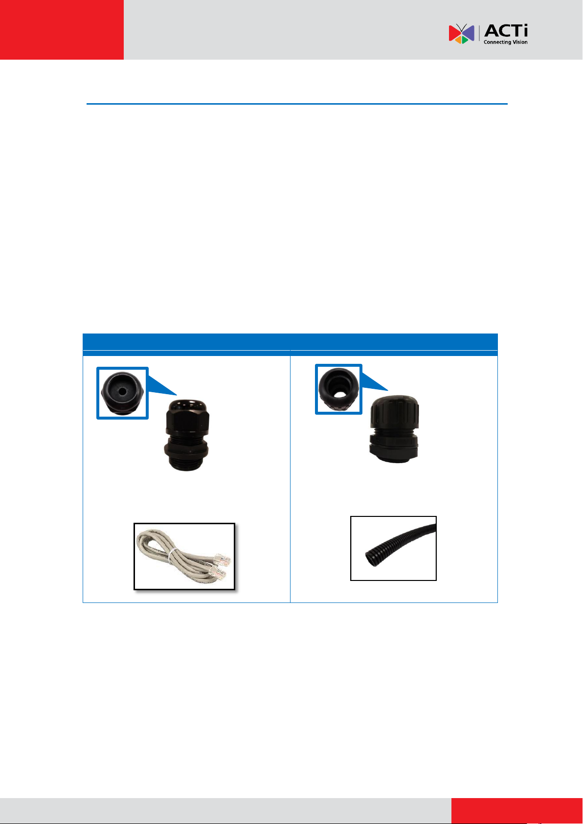
Cable Gland
Conduit Gland
For use with an Exterior-grade Ethernet
cable (not included in the package).
For use with 1/2” flexible conduit (not
included in the package)
Step 1: Prepare for Waterproof Installation
The camera comes with two (2) glands used for waterproof installation:
Cable Gland: For use with an Exterior-grade Ethernet cable. Exterior-grade Ethernet
cables are already waterproof. Note that throughout this documentation, this solution is
referred to as the Waterproof Solution with Naked Cable.
Conduit Gland: For use with a flexible conduit. This solution is recommended when an
exterior-grade Ethernet cable is not available or other cables, such as power adapter,
DI/DO devices, etc., will be connected to the camera. Note that throughout this
documentation, this solution is referred to as the Waterproof Solution with Conduit.
1. Determine the type of waterproof solution that is applicable to your installation requirements
and prepare the necessary accessories or purchase extra materials.
4
www.acti.com
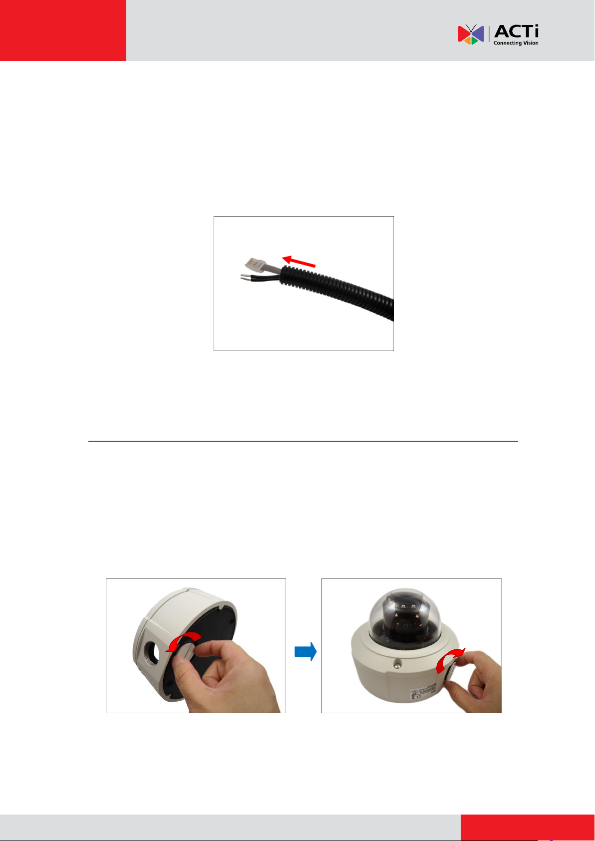
2. From this point:
When doing the Waterproof Solution with Naked Cable, skip this step.
When doing the Waterproof Solution with Conduit, pull the network cable through
the flex conduit. If connecting other input/output devices or an external power
adapter, pull the cables through the flex conduit without connectors. The terminal
blocks will be attached once the cables pass through the camera hole later.
Installation Guide
Step 2: Prepare the Camera for Installation
NOTE: To avoid scratches or leaving fingerprints on the dome cover, it is recommended to retain
the plastic covering the dome cover until the camera is completely installed. However, the plastic
has been removed on some of the pictures in this documentation to show clarity of the
procedures being described.
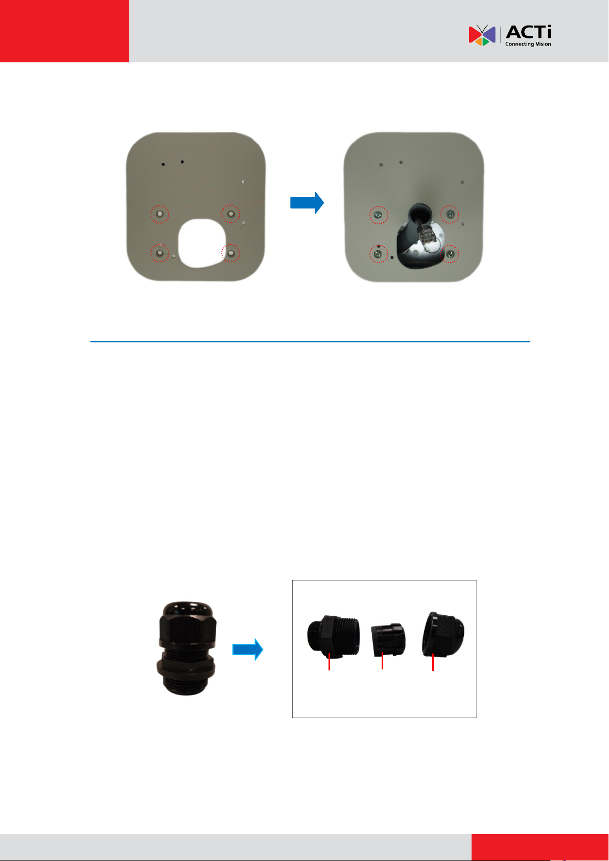
1. Remove the metal cap covering the bottom hole of the camera, and attach the cap to the side
hole to close it. The cable will be routed to pass this hole from the gang box later.
5

www.acti.com
Installation Guide
2. With the bundled hex screwdriver, loosen the three (3) screws securing the dome cover.
3. Carefully lift to open the dome cover and place it on the side of the camera.
NOTE: Do not abruptly lift the dome cover; it is attached to the camera with a spring wire.
4. If necessary, insert a memory card, with the metallic contacts facing down, into the card slot
of the camera. Push the card until it clicks into place.
6
www.acti.com
Installation Guide
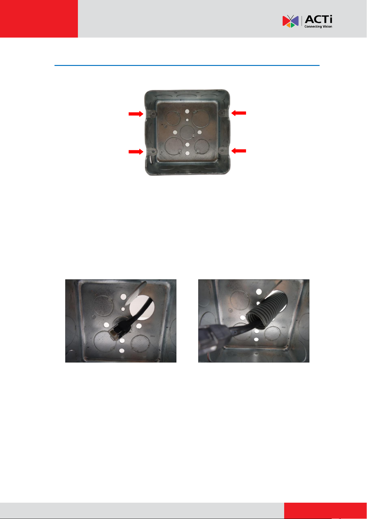
Step 3: Install the Gang Box
Before installation, note that the gang box must be installed with the orientation as shown below:
Depending on your installation environment, the gang box can be installed on the wall or inside
the wall. If the gang box will be installed in the wall, route enough length of network cable or
flex conduit inside the wall to pass through the gang box slot.
NOTE: The succeeding procedures and images show how to do the camera installation with a
gang box installed inside the wall; same procedures apply if the gang box is on the wall.
1. Remove a knockout on the gang box where you want to route the network cable. If the gang
box will be installed in the wall, insert the network cable through this knockout at this point.
Using the Naked Cable Solution Using the Flex Conduit Solution
2. Install the gang box on or inside the wall with the orientation as shown above. If the gang
box is installed on the wall, insert the network cable through the knockout after installing
the gang box on the wall.
7
www.acti.com
Installation Guide
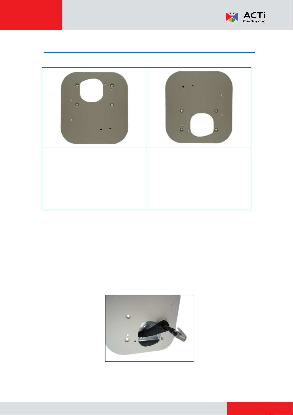
The gang box will be on the upper side of the
converter. This orientation is recommended if
the camera is installed indoors or the gang
box is installed inside the wall.
The gang box will be on the lower side of the
converter. This orientation is recommended if
the gang box is installed on the wall and the
cable be routed along the wall. This way, the
cable will be routed with a downward position
which will be an added protection against
possible water leak.
Step 4: Install the Gang Box Converter
The Gang Box Converter can be attached to the gang box by either of the following orientation:
Determine the most appropriate orientation for your installation environment.
NOTE: The succeeding procedures and images show how to do the camera installation with a
gang box installed inside the wall; same procedures apply if the gang box is on the wall.
1. Route the network cable to pass through the cable hole of the gang box converter.
NOTE: The image below shows the flex conduit through the gang box converter, same
procedure applies when using the naked cable.
8
www.acti.com
Installation Guide
Body
(with Washer)
Sealing Insert
with Claw
Clamping
Nut
2. Install the gang box converter onto the gang box using the screws included in the gang box
package. Note the screw holes to use to secure the converter to the gang box.
Step 5: Connect the Cable(s)
Follow the procedures to connect the cable(s) based on your selected waterproof solution:
Waterproof Solution with Naked Cable, see Waterproof Solution with Naked Cable
below.
Waterproof Solution with Conduit, see Waterproof Solution with Conduit on page
12
Waterproof Solution with Naked Cable
This section describes the procedures in using the bundled cable gland and an exterior-grade
Ethernet cable.
1. Disassemble the cable gland as shown below:
9
www.acti.com
Installation Guide
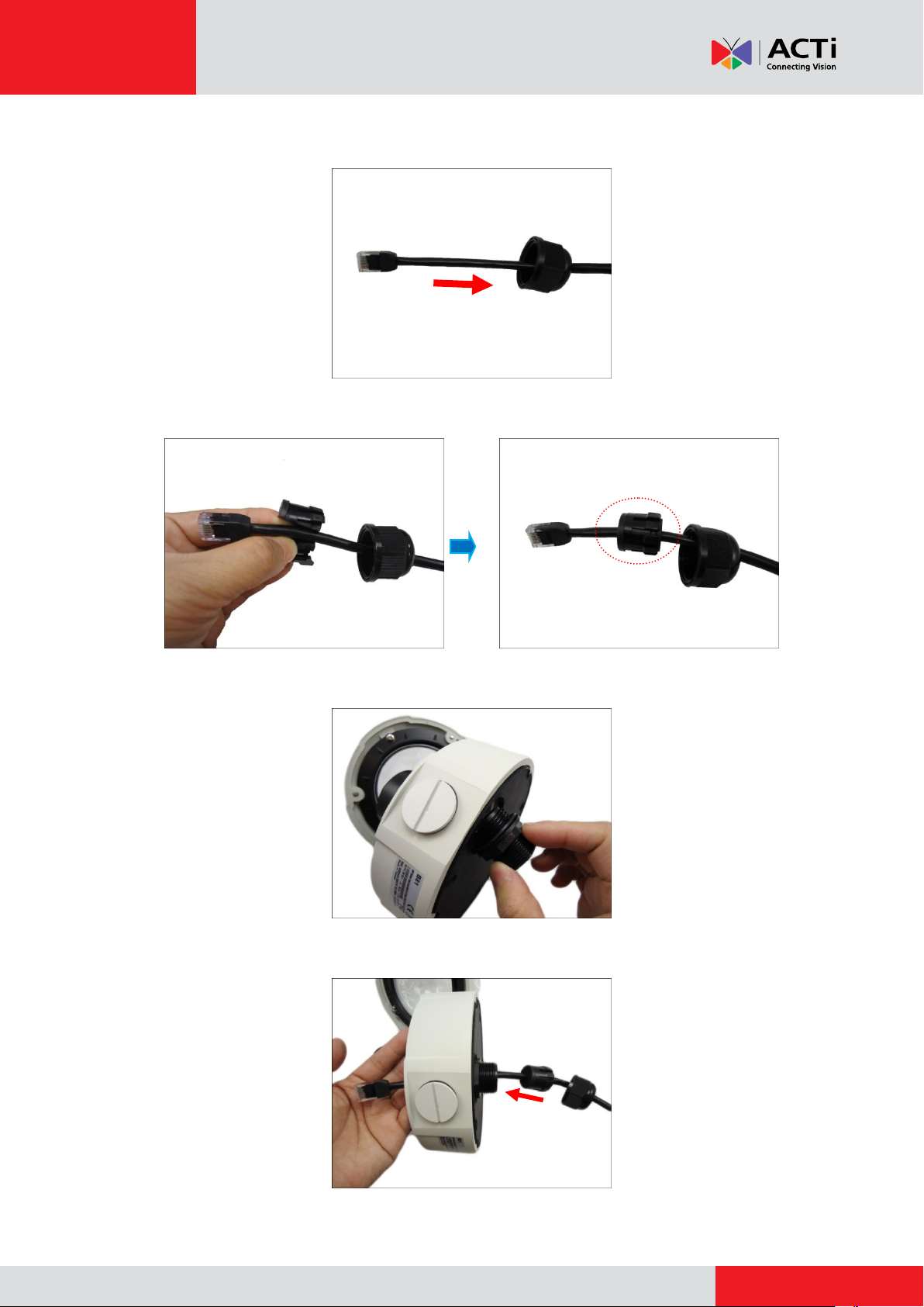
2. Insert the clamping nut into the Ethernet cable.
3. Insert the sealing insert with claw.
4. Attach the cable gland body to the hole of the camera.
5. Pull the network cable through the bottom hole of the camera.
10
www.acti.com
Installation Guide
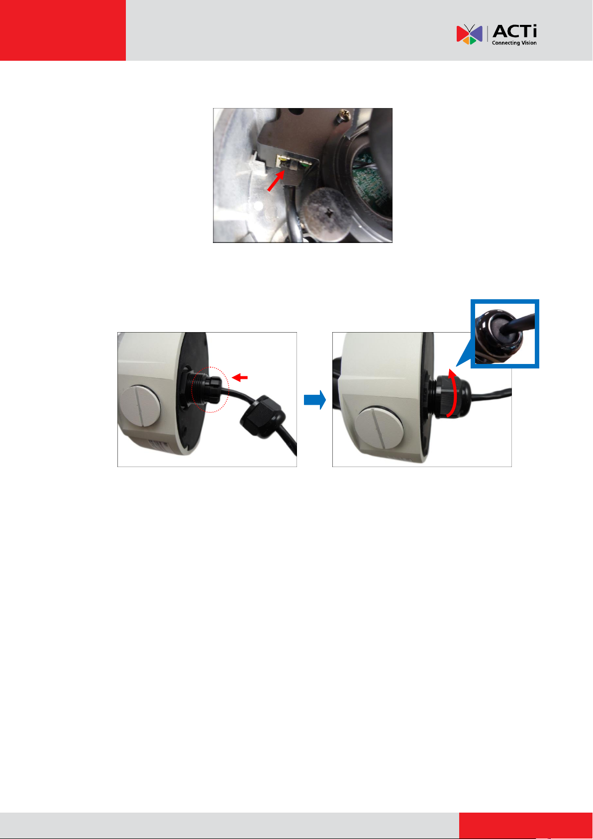
6. Connect the network cable to the Ethernet port of the camera.
7. Insert the sealing insert with the claw into the gland body and then attach the clamping nut to
complete the cable solution.
NOTE: Make sure the clamping nut is tightly attached to the cable gland body and the sealing
insert is squeezed tightly.
8. Proceed with Step 6: Install the Camera on page 16.
11
 Loading...