


QC Series
Installation and Operation Manual
Phone: 800.894.0412 - Fax: 208.368.0415 - www.ctiautomation.net - e.mail: info@ctiautomation.net
1.0GENERAL
1.1PRODUCTS COVERED IN THIS MANUAL
This manual covers the AC Tech QC1000, QC2000, and QC3000 Variable Frequency Drives.
1.2PRODUCT CHANGES
AC Technology Corporation reserves the right to discontinue or make modifications to the design of its products and manuals without prior notice, and holds no obligation to make modifications to products sold previously. AC Technology Corporation also holds no liability for losses of any kind which may result from this action. Instruction manuals with the most up-to-date information are available for download from the AC Tech website (www.actechdrives.com).
1.3WARRANTY
AC Technology Corporation warrants the QC Series AC motor control to be free of defects in material and workmanship for a period of eighteen months from the date of sale to the user, or two years from the date of shipment, which ever occurs first. Any control component, which under normal use, becomes defective, within the stated warranty time period, shall be returned to AC Technology Corporation, freight prepaid, for examination. AC Technology Corporation reserves the right to make the final determination as to the validity of a warranty claim, and sole obligation is to repair or replace only components which have been rendered defective due to faulty material or workmanship. No warranty claim will be accepted for components which have been damaged due to mishandling, improper installation, unauthorized repair and/or alteration of the product, operation in excess of design specifications or other misuse, or improper maintenance. AC Technology Corporation makes no warranty that its products are compatible with any other equipment, or to any specific application, to which they may be applied and shall not be held liable for any other consequential damage or injury arising from the use of its products.
This warranty is in lieu of all other warranties, expressed or implied. No other person, firm or corporation is authorized to assume, for AC Technology Corporation, any other liability in connection with the demonstration or sale of its products.
1.4RECEIVING
Inspect all cartons for damage which may have occurred during shipping. Carefully unpack equipment and inspect thoroughly for damage or shortage. Report any damage to carrier and/or shortages to supplier. All major components and connections should be examined for damage and tightness, with special attention given to PC boards, plugs, knobs and switches.
1.5CUSTOMER MODIFICATION
AC Technology Corporation, its sales representatives and distributors, welcome the opportunity to assist our customers in applying our products. Many customizing options are available to aid in this function. AC Technology Corporation cannot assume responsibility for any modifications not authorized by its engineering department.
1
Phone: 800.894.0412 - Fax: 208.368.0415 - www.ctiautomation.net - e.mail: info@ctiautomation.net
2.0QC SERIES SPECIFICATIONS
Storage Temperature
Ambient Operating Temperature (with 8 kHz or lower carrier, derate for higher carriers)
Ambient Humidity
Altitude
Input Line Voltages
Input Voltage Tolerance
Input Frequency Tolerance
Output Wave Form
Output Frequency
Carrier Frequency
Frequency Stability
Efficiency
Power Factor (displacement)
Service Factor
Overload Current Capacity
(based on drive output current rating)
Speed Reference Follower
Control Voltage
Analog Outputs
-20° to 70° C |
|
|
|
Chassis: |
-10 to 50° |
C (40° C for QC3000) |
|
Type 1 |
Enclosed |
-10 to 50° |
C (40° C for QC3000) |
Type 4 |
/ 12 Enclosed |
-10 to 40° |
C |
Type 12 Enclosed |
-10 to 40° |
C |
|
Type 4X Enclosed |
-10 to 40° |
C |
|
Less than 95% (non-condensing)
3300 feet (1000 meters) above sea level without derating
200/240 Vac, 400/480 Vac, and 480/590 Vac
+10%, -15%
48 to 62 Hz
Sine Coded PWM
0-120 Hz Standard, 0 - 650 Hz Optional
1.5, 8, 10, or 12 kHz
+ 0.00006% / ° C
97% or better
0.96 or better
1.00
150 % for one minute (QC1000/2000)
120 % for one minute (QC3000)
0-10 VDC, or 4-20 mA
24 VDC
0-10 VDC, 2-10 VDC, 4-20 mA Proportional to speed or load
|
12 VDC Pulse Train (40-50% Duty Cycle) |
|
Proportional to speed |
Digital Outputs |
Form C relays: 2A at 24 VDC or 120 Vac |
|
Open-collector output: 40 mA at 30 VDC |
2
Phone: 800.894.0412 - Fax: 208.368.0415 - www.ctiautomation.net - e.mail: info@ctiautomation.net

3.0QC SERIES MODEL DESIGNATION CODE
The model number of a QC Series drive gives a full description of the basic drive unit (see example below).
EXAMPLE: Q14005HB
(QC1000, 480 Vac, 5 HP, Type 1 Enclosure with extended enclosure)
Q1 |
4 |
005 |
H |
B |
- XXX |
Series:
Q1 = QC1000 Series - Constant Torque - NEMA 1 and Chassis
Q2 = QC2000 Series - Constant Torque - NEMA 4 / 12 & 4X
Q3 = QC3000 Series - Variable Torque - NEMA 1 and Chassis
Input Voltage:
2 = 240/200Vac (For 208 and 240 Vac; 50 or 60 Hz)
4= 480/400Vac (For 380, 415, 440, 460 and 480 Vac; 50 or 60 Hz)
5= 590/480Vac (For 440, 460, 480, 575 and 600 Vac; 50 or 60 Hz)
Horsepower: |
|
|
|
|
|
|
001 |
= 1 Hp |
015 |
= 15 Hp |
060 |
= 60 Hp |
250 = 250 Hp |
002 |
= 2 Hp |
020 |
= 20 Hp |
075 |
= 75Hp |
|
003 |
= 3 Hp |
025 |
= 25 Hp |
100 |
= 100Hp |
|
005 |
= 5 Hp |
030 |
= 30 Hp |
125 |
= 125Hp |
|
008 |
= 7½ Hp |
040 |
= 40 Hp |
150 = 150 Hp |
|
|
010 |
= 10 Hp |
050 |
= 50 Hp |
200 = 200 Hp |
|
|
Extended Enclosures: |
|
|
|
|
||
H = |
Extended enclosure. |
|
|
|
||
No character indicates standard height enclosure.
Required for line reactor option. Line reactors are standard on 240 Vac models from 25 to 60 Hp, 480 Vac models from 25 to 250 Hp, and 590 Vac from 5 to 200 Hp.
Enclosure Type:
A= Chassis - Open Frame
B= NEMA 1 - General Purpose, vented: Indoor
C= NEMA 4 - Washdown: Indoor / Outdoor (NEMA 4 rating exceeds NEMA 12 rating)
D= NEMA 12 - Dust-tight and Drip-tight: Indoor
E= NEMA 4X - Washdown, Stainless steel: Indoor / Outdoor
Special Designation:
Non-standard special models have a three digit suffix.
3
Phone: 800.894.0412 - Fax: 208.368.0415 - www.ctiautomation.net - e.mail: info@ctiautomation.net
4.0QC SERIES DIMENSIONS
4.1QC1000 - CHASSIS AND TYPE 1 ENCLOSED
W |
D |
H
Q |
Q |
|
Conduit Holes: |
|
If Q = 2.12", all = 1.13" dia. |
P |
If Q = 2.50", middle = 1.13" dia. |
|
left & right = 1.38" dia. |
N |
|
V
 U
U 
R
 2R
2R
T
Dia.
Mounting Tab Detail
|
INPUT |
|
|
|
|
|
|
|
|
|
|
|
HP |
VOLTAGE |
MODEL |
H |
W |
D |
N |
P |
Q |
R |
T |
U |
V |
|
|
|
|
|
|
|
|
|
|
|
|
|
1 |
240 / 200 |
Q12001 |
12.00 |
7.44 |
5.91 |
3.72 |
2.75 |
2.12 |
1.00 |
0.28 |
0.37 |
0.68 |
|
480 / 400 |
Q14001 |
12.00 |
7.44 |
5.91 |
3.72 |
2.75 |
2.12 |
1.00 |
0.28 |
0.37 |
0.68 |
|
590 / 480 |
Q15001 |
12.00 |
7.44 |
5.91 |
3.72 |
2.75 |
2.12 |
1.00 |
0.28 |
0.37 |
0.68 |
|
|
|
|
|
|
|
|
|
|
|
|
|
2 |
240 / 200 |
Q12002 |
12.00 |
7.44 |
7.91 |
3.72 |
4.75 |
2.12 |
1.00 |
0.28 |
0.37 |
0.68 |
|
480 / 400 |
Q14002 |
12.00 |
7.44 |
7.91 |
3.72 |
4.75 |
2.12 |
1.00 |
0.28 |
0.37 |
0.68 |
|
590 / 480 |
Q15002 |
12.00 |
7.44 |
7.91 |
3.72 |
4.75 |
2.12 |
1.00 |
0.28 |
0.37 |
0.68 |
|
|
|
|
|
|
|
|
|
|
|
|
|
3 |
240 / 200 |
Q12003 |
12.00 |
7.44 |
7.91 |
3.72 |
4.75 |
2.12 |
1.00 |
0.28 |
0.37 |
0.68 |
|
480 / 400 |
Q14003 |
12.00 |
7.44 |
7.91 |
3.72 |
4.75 |
2.12 |
1.00 |
0.28 |
0.37 |
0.68 |
|
590 / 480 |
Q15003 |
12.00 |
7.44 |
7.91 |
3.72 |
4.75 |
2.12 |
1.00 |
0.28 |
0.37 |
0.68 |
|
|
|
|
|
|
|
|
|
|
|
|
|
5 |
480 / 400 |
Q14005 |
12.00 |
7.44 |
7.91 |
3.72 |
4.75 |
2.12 |
1.00 |
0.28 |
0.37 |
0.68 |
|
590 / 480 |
Q15005 |
15.50 |
7.44 |
7.91 |
3.72 |
4.75 |
2.12 |
1.00 |
0.28 |
0.37 |
0.68 |
|
|
|
|
|
|
|
|
|
|
|
|
|
7.5 |
240 / 200 |
Q12008 |
14.00 |
8.88 |
9.50 |
4.44 |
5.75 |
2.50 |
1.00 |
0.28 |
0.37 |
0.68 |
|
480 / 400 |
Q14008 |
12.00 |
7.44 |
7.91 |
3.72 |
4.75 |
2.12 |
1.00 |
0.28 |
0.37 |
0.68 |
|
590 / 480 |
Q15008 |
15.50 |
7.44 |
7.91 |
3.72 |
4.75 |
2.12 |
1.00 |
0.28 |
0.37 |
0.68 |
|
|
|
|
|
|
|
|
|
|
|
|
|
10 |
240 / 200 |
Q12010 |
14.00 |
8.88 |
9.50 |
4.44 |
5.75 |
2.50 |
1.00 |
0.28 |
0.37 |
0.68 |
|
480 / 400 |
Q14010 |
14.00 |
8.88 |
9.50 |
4.44 |
5.75 |
2.50 |
1.00 |
0.28 |
0.37 |
0.68 |
|
590 / 480 |
Q15010 |
19.00 |
8.88 |
9.84 |
4.44 |
6.13 |
2.50 |
1.00 |
0.28 |
0.37 |
0.68 |
|
|
|
|
|
|
|
|
|
|
|
|
|
15 |
240 / 200 |
Q12015 |
14.00 |
8.88 |
9.50 |
4.44 |
5.75 |
2.50 |
1.00 |
0.28 |
0.37 |
0.68 |
|
480 / 400 |
Q14015 |
14.00 |
8.88 |
9.50 |
4.44 |
5.75 |
2.50 |
1.00 |
0.28 |
0.37 |
0.68 |
|
590 / 480 |
Q15015 |
19.00 |
8.88 |
9.84 |
4.44 |
6.13 |
2.50 |
1.00 |
0.28 |
0.37 |
0.68 |
|
|
|
|
|
|
|
|
|
|
|
|
|
20 |
240 / 200 |
Q12020 |
19.00 |
8.88 |
9.84 |
4.44 |
6.13 |
2.50 |
1.00 |
0.28 |
0.37 |
0.68 |
|
480 / 400 |
Q14020 |
19.00 |
8.88 |
9.84 |
4.44 |
6.13 |
2.50 |
1.00 |
0.28 |
0.37 |
0.68 |
|
590 / 480 |
Q15020 |
25.00 |
8.88 |
10.50 |
4.44 |
6.50 |
2.50 |
1.50 |
0.36 |
0.37 |
0.68 |
|
|
|
|
|
|
|
|
|
|
|
|
|
4
Phone: 800.894.0412 - Fax: 208.368.0415 - www.ctiautomation.net - e.mail: info@ctiautomation.net

4.1QC1000 - CHASSIS AND TYPE 1 ENCLOSED
W |
D |
H
 Q
Q  Q
Q 
P
N
Conduit Holes:
If Q = 2.50", middle = 1.13" dia. left & right = 1.38" dia.
If Q = 2.62", left = 1.13" dia. middle & right = 1.38" dia.
If Q = 3.12", left = 1.13" dia. middle & right = 1.75" dia.
If Q = 4.50", left = 1.13" dia. middle & right = 2.50" dia.
V
 U
U 
R
 2R
2R
T
Dia.
Mounting Tab Detail
|
INPUT |
|
|
|
|
|
|
|
|
|
|
|
HP |
VOLTAGE |
MODEL |
H |
W |
D |
N |
P |
Q |
R |
T |
U |
V |
|
|
|
|
|
|
|
|
|
|
|
|
|
25 |
240 / 200 |
Q12025 |
25.00 |
8.88 |
10.50 |
4.44 |
6.50 |
2.50 |
1.50 |
0.36 |
0.37 |
0.68 |
|
480 / 400 |
Q14025 |
25.00 |
8.88 |
10.50 |
4.44 |
6.50 |
2.50 |
1.50 |
0.36 |
0.37 |
0.68 |
|
590 / 480 |
Q15025 |
25.00 |
8.88 |
10.50 |
4.44 |
6.50 |
2.50 |
1.50 |
0.36 |
0.37 |
0.68 |
|
|
|
|
|
|
|
|
|
|
|
|
|
30 |
240 / 200 |
Q12030 |
25.00 |
8.88 |
10.50 |
5.56 |
6.50 |
2.50 |
1.50 |
0.36 |
0.37 |
0.68 |
|
480 / 400 |
Q14030 |
25.00 |
8.88 |
10.50 |
4.44 |
6.50 |
2.50 |
1.50 |
0.36 |
0.37 |
0.68 |
|
590 / 480 |
Q15030 |
25.00 |
8.88 |
10.50 |
4.44 |
6.50 |
2.50 |
1.50 |
0.36 |
0.37 |
0.68 |
|
|
|
|
|
|
|
|
|
|
|
|
|
40 |
240 / 200 |
Q12040 |
25.00 |
13.00 |
10.50 |
5.56 |
6.50 |
2.62 |
1.50 |
0.36 |
0.37 |
0.68 |
|
480 / 400 |
Q14040 |
25.00 |
13.00 |
10.50 |
5.56 |
6.50 |
2.62 |
1.50 |
0.36 |
0.37 |
0.68 |
|
590 / 480 |
Q15040 |
25.00 |
13.00 |
10.50 |
5.56 |
6.50 |
2.62 |
1.50 |
0.36 |
0.37 |
0.68 |
|
|
|
|
|
|
|
|
|
|
|
|
|
50 |
480 / 400 |
Q14050 |
25.00 |
13.00 |
10.50 |
5.56 |
6.50 |
2.62 |
1.50 |
0.36 |
0.37 |
0.68 |
|
590 / 480 |
Q15050 |
25.00 |
13.00 |
10.50 |
5.56 |
6.50 |
2.62 |
1.50 |
0.36 |
0.37 |
0.68 |
|
|
|
|
|
|
|
|
|
|
|
|
|
60 |
240 / 200 |
Q12060 |
29.00 |
16.64 |
11.85 |
7.14 |
6.88 |
3.12 |
1.50 |
0.44 |
0.49 |
0.92 |
|
480 / 400 |
Q14060 |
29.00 |
16.64 |
11.85 |
7.14 |
6.88 |
3.12 |
1.50 |
0.44 |
0.49 |
0.92 |
|
590 / 480 |
Q15060 |
29.00 |
16.64 |
11.85 |
7.14 |
6.88 |
3.12 |
1.50 |
0.44 |
0.49 |
0.92 |
|
|
|
|
|
|
|
|
|
|
|
|
|
75 |
480 / 400 |
Q14075 |
29.00 |
16.64 |
11.85 |
7.14 |
6.88 |
3.12 |
1.50 |
0.44 |
0.49 |
0.92 |
|
590 / 480 |
Q15075 |
29.00 |
16.64 |
11.85 |
7.14 |
6.88 |
3.12 |
1.50 |
0.44 |
0.49 |
0.92 |
|
|
|
|
|
|
|
|
|
|
|
|
|
100 |
480 / 400 |
Q14100 |
29.00 |
24.42 |
11.85 |
11.12 |
6.50 |
4.50 |
1.50 |
0.44 |
0.49 |
0.92 |
|
590 / 480 |
Q15100 |
29.00 |
24.42 |
11.85 |
11.12 |
6.50 |
4.50 |
1.50 |
0.44 |
0.49 |
0.92 |
|
|
|
|
|
|
|
|
|
|
|
|
|
125 |
480 / 400 |
Q14125 |
29.00 |
24.42 |
11.85 |
11.12 |
6.50 |
4.50 |
1.50 |
0.44 |
0.49 |
0.92 |
|
590 / 480 |
Q15125 |
29.00 |
24.42 |
11.85 |
11.12 |
6.50 |
4.50 |
1.50 |
0.44 |
0.49 |
0.92 |
|
|
|
|
|
|
|
|
|
|
|
|
|
150 |
480 / 400 |
Q14150 |
29.00 |
36.66 |
11.85 |
|
SEE SECTION 4.7 - PAGE 11 |
|
||||
|
590 / 480 |
Q15150 |
29.00 |
36.66 |
11.85 |
|
|
|||||
|
|
|
|
|
|
|
|
|||||
|
|
|
|
|
|
|
|
|
|
|
|
|
5
Phone: 800.894.0412 - Fax: 208.368.0415 - www.ctiautomation.net - e.mail: info@ctiautomation.net

4.2QC2000 - TYPE 4/12 AND 4X ENCLOSED
D
H
W
 Q
Q  Q
Q 
P
W  2
2
Conduit Holes:
If Q = 2.12", all = 1.13" dia.
If Q = 2.50", middle = 1.13" dia. left & right = 1.38" dia.
V
 U
U 
R
 2R
2R
T
Dia.
Mounting Tab Detail
|
INPUT |
|
|
|
|
|
|
|
|
|
|
HP |
VOLTAGE |
MODEL |
H |
W |
D |
P |
Q |
R |
T |
U |
V |
|
|
|
|
|
|
|
|
|
|
|
|
1 |
240 / 200 |
Q22001 |
13.00 |
7.88 |
6.19 |
3.50 |
2.12 |
1.00 |
0.28 |
0.37 |
0.68 |
|
480 / 400 |
Q24001 |
13.00 |
7.88 |
6.19 |
3.50 |
2.12 |
1.00 |
0.28 |
0.37 |
0.68 |
|
590 / 480 |
Q25001 |
13.00 |
7.88 |
6.19 |
3.50 |
2.12 |
1.00 |
0.28 |
0.37 |
0.68 |
|
|
|
|
|
|
|
|
|
|
|
|
2 |
240 / 200 |
Q22002 |
13.00 |
7.88 |
7.25 |
4.56 |
2.12 |
1.00 |
0.28 |
0.37 |
0.68 |
|
480 / 400 |
Q24002 |
13.00 |
7.88 |
6.19 |
3.50 |
2.12 |
1.00 |
0.28 |
0.37 |
0.68 |
|
590 / 480 |
Q25002 |
13.00 |
7.88 |
6.19 |
3.50 |
2.12 |
1.00 |
0.28 |
0.37 |
0.68 |
|
|
|
|
|
|
|
|
|
|
|
|
3 |
240 / 200 |
Q22003 |
13.00 |
7.88 |
7.25 |
4.56 |
2.12 |
1.00 |
0.28 |
0.37 |
0.68 |
|
480 / 400 |
Q24003 |
13.00 |
7.88 |
7.25 |
4.56 |
2.12 |
1.00 |
0.28 |
0.37 |
0.68 |
|
590 / 480 |
Q25003 |
13.00 |
7.88 |
7.25 |
4.56 |
2.12 |
1.00 |
0.28 |
0.37 |
0.68 |
|
|
|
|
|
|
|
|
|
|
|
|
5 |
480 / 400 |
Q24005 |
16.00 |
9.70 |
7.50 |
4.81 |
2.12 |
1.00 |
0.28 |
0.37 |
0.68 |
|
590 / 480 |
Q25005 |
16.00 |
9.70 |
7.50 |
4.81 |
2.12 |
1.00 |
0.28 |
0.37 |
0.68 |
|
|
|
|
|
|
|
|
|
|
|
|
7.5 |
240 / 200 |
Q22008 |
19.00 |
11.38 |
8.83 |
5.63 |
2.50 |
1.00 |
0.28 |
0.37 |
0.68 |
|
480 / 400 |
Q24008 |
16.00 |
9.70 |
7.50 |
4.81 |
2.12 |
1.00 |
0.28 |
0.37 |
0.68 |
|
590 / 480 |
Q25008 |
16.00 |
9.70 |
7.50 |
4.81 |
2.12 |
1.00 |
0.28 |
0.37 |
0.68 |
|
|
|
|
|
|
|
|
|
|
|
|
10 |
240 / 200 |
Q22010 |
19.00 |
11.38 |
8.83 |
5.63 |
2.50 |
1.00 |
0.28 |
0.37 |
0.68 |
|
480 / 400 |
Q24010 |
19.00 |
11.38 |
8.83 |
5.63 |
2.50 |
1.00 |
0.28 |
0.37 |
0.68 |
|
590 / 480 |
Q25010 |
19.00 |
11.38 |
8.83 |
5.63 |
2.50 |
1.00 |
0.28 |
0.37 |
0.68 |
|
|
|
|
|
|
|
|
|
|
|
|
15 |
240 / 200 |
Q22015 |
19.00 |
11.38 |
8.83 |
5.63 |
2.50 |
1.00 |
0.28 |
0.37 |
0.68 |
|
480 / 400 |
Q24015 |
19.00 |
11.38 |
8.83 |
5.63 |
2.50 |
1.00 |
0.28 |
0.37 |
0.68 |
|
590 / 480 |
Q25015 |
19.00 |
11.38 |
8.83 |
5.63 |
2.50 |
1.00 |
0.28 |
0.37 |
0.68 |
|
|
|
|
|
|
|
|
|
|
|
|
20 |
240 / 200 |
Q22020 |
29.00 |
11.74 |
9.78 |
5.88 |
2.50 |
1.50 |
0.36 |
0.37 |
0.68 |
|
480 / 400 |
Q24020 |
29.00 |
11.74 |
9.78 |
5.88 |
2.50 |
1.50 |
0.36 |
0.37 |
0.68 |
|
590 / 480 |
Q25020 |
29.00 |
11.74 |
9.78 |
5.88 |
2.50 |
1.50 |
0.36 |
0.37 |
0.68 |
|
|
|
|
|
|
|
|
|
|
|
|
25 |
240 / 200 |
Q22025 |
29.00 |
11.74 |
10.98 |
7.08 |
2.50 |
1.50 |
0.36 |
0.37 |
0.68 |
|
480 / 400 |
Q24025 |
29.00 |
11.74 |
9.78 |
5.88 |
2.50 |
1.50 |
0.36 |
0.37 |
0.68 |
|
590 / 480 |
Q25025 |
29.00 |
11.74 |
9.78 |
5.88 |
2.50 |
1.50 |
0.36 |
0.37 |
0.68 |
|
|
|
|
|
|
|
|
|
|
|
|
30 |
480 / 400 |
Q24030 |
29.00 |
11.74 |
10.98 |
7.08 |
2.50 |
1.50 |
0.36 |
0.37 |
0.68 |
|
590 / 480 |
Q25030 |
29.00 |
11.74 |
10.98 |
7.08 |
2.50 |
1.50 |
0.36 |
0.37 |
0.68 |
|
|
|
|
|
|
|
|
|
|
|
|
Phone: 800.894.0412 - Fax: 208.368.0415 - www.ctiautomation.net - e.mail: info@ctiautomation.net

4.3QC2000 - TYPE 12 ENCLOSED
|
|
D |
AIR FLOW |
AIR FLOW |
|
|
If H = 31.00" |
H |
|
Y = 22.50" |
|
|
Y |
|
|
If H > 37.00" |
|
|
Y = 27.00" |
|
W |
|
V |
|
|
|
Q Q |
Conduit Holes: |
U |
If Q = 2.62", left = 1.13" dia. middle & right = 1.38" dia.
P
If Q = 3.13", left = 1.13" dia. middle & right = 1.75" dia.
N |
If Q = 4.50", left = 1.13" dia. |
middle & right = 2.50" dia. |
|
2R |
T |
R |
|
|
Dia. |
|
Mounting Tab Detail
|
INPUT |
|
|
|
|
|
|
|
|
|
|
|
HP |
VOLTAGE |
MODEL |
H |
W |
D |
N |
P |
Q |
R |
T |
U |
V |
|
|
|
|
|
|
|
|
|
|
|
|
|
30 |
240 / 200 |
Q22030 |
31.00 |
14.00 |
11.86 |
6.00 |
7.50 |
2.62 |
1.50 |
0.36 |
0.37 |
0.68 |
|
|
|
|
|
|
|
|
|
|
|
|
|
40 |
240 / 200 |
Q22040 |
31.00 |
14.00 |
11.86 |
6.00 |
7.50 |
2.62 |
1.50 |
0.36 |
0.37 |
0.68 |
|
480 / 400 |
Q24040 |
31.00 |
14.00 |
11.86 |
6.00 |
7.50 |
2.62 |
1.50 |
0.36 |
0.37 |
0.68 |
|
590 / 480 |
Q25040 |
31.00 |
14.00 |
11.86 |
6.00 |
7.50 |
2.62 |
1.50 |
0.36 |
0.37 |
0.68 |
|
|
|
|
|
|
|
|
|
|
|
|
|
50 |
480 / 400 |
Q24050 |
31.00 |
14.00 |
11.86 |
6.00 |
7.50 |
2.62 |
1.50 |
0.36 |
0.37 |
0.68 |
|
590 / 480 |
Q25050 |
31.00 |
14.00 |
11.86 |
6.00 |
7.50 |
2.62 |
1.50 |
0.36 |
0.37 |
0.68 |
|
|
|
|
|
|
|
|
|
|
|
|
|
60 |
240 / 200 |
Q22060 |
37.00 |
18.00 |
13.30 |
7.50 |
8.00 |
3.13 |
1.50 |
0.49 |
0.50 |
0.92 |
|
480 / 400 |
Q24060 |
37.00 |
18.00 |
13.30 |
7.50 |
8.00 |
3.13 |
1.50 |
0.49 |
0.50 |
0.92 |
|
590 / 480 |
Q25060 |
37.00 |
18.00 |
13.30 |
7.50 |
8.00 |
3.13 |
1.50 |
0.49 |
0.50 |
0.92 |
|
|
|
|
|
|
|
|
|
|
|
|
|
75 |
480 / 400 |
Q24075 |
37.00 |
18.00 |
13.30 |
7.50 |
8.00 |
3.13 |
1.50 |
0.49 |
0.50 |
0.92 |
|
590 / 480 |
Q25075 |
37.00 |
18.00 |
13.30 |
7.50 |
8.00 |
3.13 |
1.50 |
0.49 |
0.50 |
0.92 |
|
|
|
|
|
|
|
|
|
|
|
|
|
100 |
480 / 400 |
Q24100 |
39.00 |
26.00 |
13.30 |
11.50 |
8.00 |
4.50 |
1.50 |
0.49 |
0.50 |
0.92 |
|
590 / 480 |
Q25100 |
39.00 |
26.00 |
13.30 |
11.50 |
8.00 |
4.50 |
1.50 |
0.49 |
0.50 |
0.92 |
|
|
|
|
|
|
|
|
|
|
|
|
|
125 |
480 / 400 |
Q24125 |
39.00 |
26.00 |
13.30 |
11.50 |
8.00 |
4.50 |
1.50 |
0.49 |
0.50 |
0.92 |
|
590 / 480 |
Q25125 |
39.00 |
26.00 |
13.30 |
11.50 |
8.00 |
4.50 |
1.50 |
0.49 |
0.50 |
0.92 |
|
|
|
|
|
|
|
|
|
|
|
|
|
7
Phone: 800.894.0412 - Fax: 208.368.0415 - www.ctiautomation.net - e.mail: info@ctiautomation.net

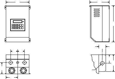
4.4QC3000 - CHASSIS AND TYPE 1 ENCLOSED
W
Q  Q
Q 
P
N
Conduit Holes:
If Q = 2.12", all = 1.13" dia.
If Q = 2.50", middle = 1.13" dia. left & right = 1.38" dia.
D
H
V
 U
U
R
 2R
2R
T
Dia.
Mounting Tab Detail
|
INPUT |
|
|
|
|
|
|
|
|
|
|
|
HP |
VOLTAGE |
MODEL |
H |
W |
D |
N |
P |
Q |
R |
T |
U |
V |
|
|
|
|
|
|
|
|
|
|
|
|
|
2 |
240 / 200 |
Q32002 |
12.00 |
7.44 |
7.91 |
3.72 |
4.75 |
2.12 |
1.00 |
0.28 |
0.37 |
0.68 |
|
480 / 400 |
Q34002 |
12.00 |
7.44 |
7.91 |
3.72 |
4.75 |
2.12 |
1.00 |
0.28 |
0.37 |
0.68 |
|
590 / 480 |
Q35002 |
12.00 |
7.44 |
7.91 |
3.72 |
4.75 |
2.12 |
1.00 |
0.28 |
0.37 |
0.68 |
|
|
|
|
|
|
|
|
|
|
|
|
|
3 |
240 / 200 |
Q32003 |
12.00 |
7.44 |
7.91 |
3.72 |
4.75 |
2.12 |
1.00 |
0.28 |
0.37 |
0.68 |
|
480 / 400 |
Q34003 |
12.00 |
7.44 |
7.91 |
3.72 |
4.75 |
2.12 |
1.00 |
0.28 |
0.37 |
0.68 |
|
590 / 480 |
Q35003 |
12.00 |
7.44 |
7.91 |
3.72 |
4.75 |
2.12 |
1.00 |
0.28 |
0.37 |
0.68 |
|
|
|
|
|
|
|
|
|
|
|
|
|
5 |
240 / 200 |
Q32005 |
12.00 |
7.44 |
7.91 |
3.72 |
4.75 |
2.12 |
1.00 |
0.28 |
0.37 |
0.68 |
|
480 / 400 |
Q34005 |
12.00 |
7.44 |
7.91 |
3.72 |
4.75 |
2.12 |
1.00 |
0.28 |
0.37 |
0.68 |
|
590 / 480 |
Q35005 |
15.50 |
7.44 |
7.91 |
3.72 |
4.75 |
2.12 |
1.00 |
0.28 |
0.37 |
0.68 |
|
|
|
|
|
|
|
|
|
|
|
|
|
7.5 |
480 / 400 |
Q34008 |
12.00 |
7.44 |
7.91 |
3.72 |
4.75 |
2.12 |
1.00 |
0.28 |
0.37 |
0.68 |
|
590 / 480 |
Q35008 |
15.50 |
7.44 |
7.91 |
3.72 |
4.75 |
2.12 |
1.00 |
0.28 |
0.37 |
0.68 |
|
|
|
|
|
|
|
|
|
|
|
|
|
10 |
240 / 200 |
Q32010 |
14.00 |
8.88 |
9.50 |
4.44 |
5.75 |
2.50 |
1.00 |
0.28 |
0.37 |
0.68 |
|
480 / 400 |
Q34010 |
12.00 |
7.44 |
7.91 |
3.72 |
4.75 |
2.12 |
1.00 |
0.28 |
0.37 |
0.68 |
|
590 / 480 |
Q35010 |
15.50 |
7.44 |
7.91 |
3.72 |
4.75 |
2.12 |
1.00 |
0.28 |
0.37 |
0.68 |
|
|
|
|
|
|
|
|
|
|
|
|
|
15 |
240 / 200 |
Q32015 |
14.00 |
8.88 |
9.50 |
4.44 |
5.75 |
2.50 |
1.00 |
0.28 |
0.37 |
0.68 |
|
480 / 400 |
Q34015 |
14.00 |
8.88 |
9.50 |
4.44 |
5.75 |
2.50 |
1.00 |
0.28 |
0.37 |
0.68 |
|
590 / 480 |
Q35015 |
19.00 |
8.88 |
9.84 |
4.44 |
6.13 |
2.50 |
1.00 |
0.28 |
0.37 |
0.68 |
|
|
|
|
|
|
|
|
|
|
|
|
|
20 |
240 / 200 |
Q32020 |
19.00 |
8.88 |
9.84 |
4.44 |
6.13 |
2.50 |
1.00 |
0.28 |
0.37 |
0.68 |
|
480 / 400 |
Q34020 |
19.00 |
8.88 |
9.84 |
4.44 |
6.13 |
2.50 |
1.00 |
0.28 |
0.37 |
0.68 |
|
590 / 480 |
Q35020 |
25.00 |
8.88 |
10.50 |
4.44 |
6.50 |
2.50 |
1.50 |
0.36 |
0.37 |
0.68 |
|
|
|
|
|
|
|
|
|
|
|
|
|
25 |
240 / 200 |
Q32025 |
25.00 |
8.88 |
10.5 |
4.44 |
6.50 |
2.50 |
1.50 |
0.36 |
0.37 |
0.68 |
|
480 / 400 |
Q34025 |
25.00 |
8.88 |
10.5 |
4.44 |
6.50 |
2.50 |
1.50 |
0.36 |
0.37 |
0.68 |
|
590 / 480 |
Q35025 |
25.00 |
8.88 |
10.5 |
4.44 |
6.50 |
2.50 |
1.50 |
0.36 |
0.37 |
0.68 |
|
|
|
|
|
|
|
|
|
|
|
|
|
8
Phone: 800.894.0412 - Fax: 208.368.0415 - www.ctiautomation.net - e.mail: info@ctiautomation.net

4.4QC3000 - CHASSIS AND TYPE 1 ENCLOSED
W |
D |
H
 Q
Q  Q
Q 
P
N
Conduit Holes:
If Q = 2.50", middle = 1.13" dia. left & right = 1.38" dia.
If Q = 2.62", left = 1.13" dia. middle & right = 1.38" dia.
If Q = 3.12", left = 1.13" dia. middle & right = 1.38" dia.
If Q = 4.50", left = 1.13" dia. middle & right = 2.50" dia.
V
 U
U 
R
 2R
2R
T
Dia.
Mounting Tab Detail
|
INPUT |
|
|
|
|
|
|
|
|
|
|
|
HP |
VOLTAGE |
MODEL |
H |
W |
D |
N |
P |
Q |
R |
T |
U |
V |
|
|
|
|
|
|
|
|
|
|
|
|
|
30 |
240 / 200 |
Q32030 |
25.00 |
8.88 |
10.50 |
4.44 |
6.50 |
2.50 |
1.50 |
0.36 |
0.37 |
0.68 |
|
480 / 400 |
Q34030 |
25.00 |
8.88 |
10.50 |
4.44 |
6.50 |
2.50 |
1.50 |
0.36 |
0.37 |
0.68 |
|
590 / 480 |
Q35030 |
25.00 |
8.88 |
10.50 |
4.44 |
6.50 |
2.50 |
1.50 |
0.36 |
0.37 |
0.68 |
|
|
|
|
|
|
|
|
|
|
|
|
|
40 |
240 / 200 |
Q32040 |
25.00 |
13.00 |
10.50 |
5.56 |
6.50 |
2.62 |
1.50 |
0.36 |
0.37 |
0.68 |
|
480 / 400 |
Q34040 |
25.00 |
13.00 |
10.50 |
5.56 |
6.50 |
2.62 |
1.50 |
0.36 |
0.37 |
0.68 |
|
590 / 480 |
Q35040 |
25.00 |
8.88 |
10.50 |
5.56 |
6.50 |
2.62 |
1.50 |
0.36 |
0.37 |
0.68 |
|
|
|
|
|
|
|
|
|
|
|
|
|
50 |
240 / 200 |
Q32050 |
25.00 |
13.00 |
10.50 |
5.56 |
6.50 |
2.62 |
1.50 |
0.36 |
0.37 |
0.68 |
|
480 / 400 |
Q34050 |
25.00 |
13.00 |
10.50 |
5.56 |
6.50 |
2.62 |
1.50 |
0.36 |
0.37 |
0.68 |
|
590 / 480 |
Q35050 |
25.00 |
13.00 |
10.50 |
5.56 |
6.50 |
2.62 |
1.50 |
0.36 |
0.37 |
0.68 |
|
|
|
|
|
|
|
|
|
|
|
|
|
60 |
240 / 200 |
Q32060 |
47.00 |
16.64 |
11.85 |
7.14 |
6.88 |
3.12 |
1.50 |
0.44 |
0.49 |
0.92 |
|
480 / 400 |
Q34060 |
25.00 |
13.00 |
10.50 |
5.56 |
6.50 |
2.62 |
1.50 |
0.36 |
0.37 |
0.92 |
|
590 / 480 |
Q35060 |
25.00 |
13.00 |
10.50 |
5.56 |
6.50 |
2.62 |
1.50 |
0.36 |
0.37 |
0.92 |
|
|
|
|
|
|
|
|
|
|
|
|
|
75 |
240 / 200 |
Q32075 |
47.00 |
16.64 |
11.85 |
7.14 |
6.88 |
3.12 |
1.50 |
0.44 |
0.49 |
0.92 |
|
480 / 400 |
Q34075 |
29.00 |
16.64 |
11.85 |
7.14 |
6.88 |
3.12 |
1.50 |
0.44 |
0.49 |
0.92 |
|
590 / 480 |
Q35075 |
29.00 |
16.64 |
11.85 |
7.14 |
6.88 |
3.12 |
1.50 |
0.44 |
0.49 |
0.92 |
|
|
|
|
|
|
|
|
|
|
|
|
|
100 |
480 / 400 |
Q34100 |
29.00 |
16.64 |
11.85 |
7.14 |
6.88 |
3.12 |
1.50 |
0.44 |
0.49 |
0.92 |
|
590 / 480 |
Q35100 |
29.00 |
16.64 |
11.85 |
7.14 |
6.88 |
3.12 |
1.50 |
0.44 |
0.49 |
0.92 |
|
|
|
|
|
|
|
|
|
|
|
|
|
125 |
480 / 400 |
Q34125 |
29.00 |
24.42 |
11.85 |
11.12 |
6.50 |
4.50 |
1.50 |
0.44 |
0.49 |
0.92 |
|
590 / 480 |
Q35125 |
29.00 |
24.42 |
11.85 |
11.12 |
6.50 |
4.50 |
1.50 |
0.44 |
0.49 |
0.92 |
|
|
|
|
|
|
|
|
|
|
|
|
|
150 |
480 / 400 |
Q34150 |
29.00 |
24.42 |
11.85 |
11.12 |
6.50 |
4.50 |
1.50 |
0.44 |
0.49 |
0.92 |
|
590 / 480 |
Q35150 |
29.00 |
24.42 |
11.85 |
11.12 |
6.50 |
4.50 |
1.50 |
0.44 |
0.49 |
0.92 |
|
|
|
|
|
|
|
|
|
|
|
|
|
200 |
480 / 400 |
Q34200 |
29.00 |
36.66 |
11.85 |
|
|
|
|
|
|
|
|
590 / 480 |
Q35200 |
29.00 |
36.66 |
11.85 |
|
SEE SECTION 4.7 - PAGE 11 |
|
||||
250 |
480 / 400 |
Q34250 |
29.00 |
36.66 |
11.85 |
|
|
|
|
|
|
|
|
|
|
|
|
|
|
|
|
|
|
|
|
Phone: 800.894.0412 - Fax: 208.368.0415 - www.ctiautomation.net - e.mail: info@ctiautomation.net
4.5QC1000 AND QC3000 - CHASSIS AND TYPE 1 EXTENDED
W |
D |
H
Q  Q
Q 
P
N
Conduit Holes:
If Q = 2.12", all = 1.13" dia.
If Q = 2.50", middle = 1.13" dia. left & right = 1.38" dia.
V
 U
U
R
 2R
2R
T
Dia.
Mounting Tab Detail
|
INPUT |
|
|
|
|
|
|
|
|
|
|
|
HP |
VOLTAGE |
MODEL |
H |
W |
D |
N |
P |
Q |
R |
T |
U |
V |
|
|
|
|
|
|
|
|
|
|
|
|
|
1 |
240 / 200 |
Q12001H |
15.50 |
7.44 |
7.91 |
3.72 |
4.75 |
2.12 |
1.00 |
0.28 |
0.37 |
0.68 |
|
480 / 400 |
Q14001H |
15.50 |
7.44 |
7.91 |
3.72 |
4.75 |
2.12 |
1.00 |
0.28 |
0.37 |
0.68 |
|
|
|
|
|
|
|
|
|
|
|
|
|
2 |
240 / 200 |
Q*2002H |
15.50 |
7.44 |
7.91 |
3.72 |
4.75 |
2.12 |
1.00 |
0.28 |
0.37 |
0.68 |
|
480 / 400 |
Q*4002H |
15.50 |
7.44 |
7.91 |
3.72 |
4.75 |
2.12 |
1.00 |
0.28 |
0.37 |
0.68 |
|
|
|
|
|
|
|
|
|
|
|
|
|
3 |
240 / 200 |
Q*2003H |
15.50 |
7.44 |
7.91 |
3.72 |
4.75 |
2.12 |
1.00 |
0.28 |
0.37 |
0.68 |
|
480 / 400 |
Q*4003H |
15.50 |
7.44 |
7.91 |
3.72 |
4.75 |
2.12 |
1.00 |
0.28 |
0.37 |
0.68 |
|
|
|
|
|
|
|
|
|
|
|
|
|
5 |
240 / 200 |
Q32005H |
15.50 |
7.44 |
7.91 |
3.72 |
4.75 |
2.12 |
1.00 |
0.28 |
0.37 |
0.68 |
|
480 / 400 |
Q*4005H |
15.50 |
7.44 |
7.91 |
3.72 |
4.75 |
2.12 |
1.00 |
0.28 |
0.37 |
0.68 |
|
|
|
|
|
|
|
|
|
|
|
|
|
7.5 |
240 / 200 |
Q12008H |
19.00 |
8.88 |
9.84 |
4.44 |
6.13 |
2.50 |
1.00 |
0.28 |
0.37 |
0.68 |
|
480 / 400 |
Q14008H |
15.50 |
7.44 |
7.91 |
3.72 |
4.75 |
2.12 |
1.00 |
0.28 |
0.37 |
0.68 |
|
|
Q34008H |
15.50 |
7.44 |
7.91 |
3.72 |
4.75 |
2.12 |
1.00 |
0.28 |
0.37 |
0.68 |
|
|
|
|
|
|
|
|
|
|
|
|
|
10 |
240 / 200 |
Q*2010H |
19.00 |
8.88 |
9.84 |
4.44 |
6.13 |
2.50 |
1.00 |
0.28 |
0.37 |
0.68 |
|
480 / 400 |
Q14010H |
19.00 |
8.88 |
9.84 |
4.44 |
6.13 |
2.50 |
1.00 |
0.28 |
0.37 |
0.68 |
|
|
Q34010H |
15.50 |
7.44 |
7.91 |
3.72 |
4.75 |
2.12 |
1.00 |
0.28 |
0.37 |
0.68 |
|
|
|
|
|
|
|
|
|
|
|
|
|
15 |
240 / 200 |
Q*2015H |
19.00 |
8.88 |
9.84 |
4.44 |
6.13 |
2.50 |
1.00 |
0.28 |
0.37 |
0.68 |
|
480 / 400 |
Q*4015H |
19.00 |
8.88 |
9.84 |
4.44 |
6.13 |
2.50 |
1.00 |
0.28 |
0.37 |
0.68 |
|
|
|
|
|
|
|
|
|
|
|
|
|
20 |
240 / 200 |
Q*2020H |
25.00 |
8.88 |
10.50 |
4.44 |
6.50 |
2.50 |
1.50 |
0.36 |
0.37 |
0.68 |
|
480 / 400 |
Q*4020H |
25.00 |
8.88 |
10.50 |
4.44 |
6.50 |
2.50 |
1.50 |
0.36 |
0.37 |
0.68 |
|
|
|
|
|
|
|
|
|
|
|
|
|
25 |
240 / 200 |
Q*2025H |
25.00 |
13.00 |
10.50 |
5.56 |
6.50 |
2.50 |
1.50 |
0.36 |
0.37 |
0.68 |
|
480 / 400 |
Q*4025H |
25.00 |
13.00 |
10.50 |
5.56 |
6.50 |
2.50 |
1.50 |
0.36 |
0.37 |
0.68 |
|
|
|
|
|
|
|
|
|
|
|
|
|
30 |
480 / 400 |
Q*4030H |
25.00 |
13.00 |
10.50 |
5.56 |
6.50 |
2.50 |
1.50 |
0.36 |
0.37 |
0.68 |
|
|
|
|
|
||||||||
NOTE: |
* = 1 or 3, depending on model. See Section 3.0 for model number breakdown. |
|
|
|
||||||||
|
|
|
|
|
|
|
|
|
|
|
|
|
10
Phone: 800.894.0412 - Fax: 208.368.0415 - www.ctiautomation.net - e.mail: info@ctiautomation.net

4.6QC2000 - TYPE 4/12 AND 4X EXTENDED
D
H
W
Q  Q
Q 
P
W 2
Conduit Holes:
If Q = 2.12", all = 1.13" dia.
If Q = 2.50", middle = 1.13" left & right = 1.38"
V
 U
U 
R
 2R
2R
T
Dia.
Mounting Tab Detail
|
INPUT |
|
|
|
|
|
|
|
|
|
|
HP |
VOLTAGE |
MODEL |
H |
W |
D |
P |
Q |
R |
T |
U |
V |
|
|
|
|
|
|
|
|
|
|
|
|
1 |
240 / 200 |
Q22001H |
16.00 |
9.70 |
7.50 |
4.81 |
2.12 |
1.00 |
0.28 |
0.37 |
0.68 |
|
480 / 400 |
Q24001H |
16.00 |
9.70 |
7.50 |
4.81 |
2.12 |
1.00 |
0.28 |
0.37 |
0.68 |
|
|
|
|
|
|
|
|
|
|
|
|
2 |
240 / 200 |
Q22002H |
16.00 |
9.70 |
7.50 |
4.81 |
2.12 |
1.00 |
0.28 |
0.37 |
0.68 |
|
480 / 400 |
Q24002H |
16.00 |
9.70 |
7.50 |
4.81 |
2.12 |
1.00 |
0.28 |
0.37 |
0.68 |
|
|
|
|
|
|
|
|
|
|
|
|
3 |
240 / 200 |
Q22003H |
16.00 |
9.70 |
7.50 |
4.81 |
2.12 |
1.00 |
0.28 |
0.37 |
0.68 |
|
480 / 400 |
Q24003H |
16.00 |
9.70 |
7.50 |
4.81 |
2.12 |
1.00 |
0.28 |
0.37 |
0.68 |
|
|
|
|
|
|
|
|
|
|
|
|
4.7MOUNTING TAB AND CONDUIT HOLE DIMENSIONS
The following diagram applies to 150 HP QC1000, 200 HP QC3000, and 250 HP QC3000 models only.
V
|
|
|
|
|
U |
N |
P |
Q |
P |
|
1.36" |
|
|
|
|
|
|
7.25" |
|
|
|
T |
3.00" |
|
|
6.50" |
|
||
|
|
Dia. |
|
||
|
|
|
|
|
1.36" |
Conduit Holes: Large holes = 3.00" |
|
|
|||
|
|
Small holes = 1.13" |
|
|
|
|
|
|
|
|
Mounting Tab Detail |
N = 7.45"
P= 9.00"
Q= 7.00"
T= 0.44"
U= 0.49"
V= 0.92"
11
Phone: 800.894.0412 - Fax: 208.368.0415 - www.ctiautomation.net - e.mail: info@ctiautomation.net

5.0QC SERIES RATINGS
Q1200, Q2200, AND Q3200 SERIES RATINGS
|
|
|
|
|
INPUT |
|
OUTPUT |
|
||
MODEL |
|
|
(240 Vac, 50 - 60 Hz) |
|
(0 - 230 Vac) |
|||||
|
|
|
|
|
|
|
|
|
|
|
|
|
|
|
|
NOMINAL |
|
|
|
|
|
MODEL |
|
|
|
|
CURRENT |
|
|
NOMINAL |
|
|
NUMBER |
|
RATED |
INPUT |
|
(AMPS) |
|
POWER |
CURRENT |
|
POWER |
(NOTE 1) |
|
HP |
PHASE |
|
(NOTE 2) |
|
(KVA) |
(AMPS) |
|
(KVA) |
Q*2001 |
|
1 |
3 |
|
4.6 |
|
1.9 |
4.0 |
|
1.6 |
|
|
|
|
|
|
|
|
|
|
|
Q*2001S |
|
1 |
1 / 3 |
|
8.5 / 4.6 |
|
2.0 / 1.9 |
4.0 |
|
1.6 |
|
|
|
|
|
|
|
|
|
|
|
Q*2002 |
|
2 |
3 |
|
8.1 |
|
3.4 |
6.8 |
|
2.7 |
|
|
|
|
|
|
|
|
|
|
|
Q*2002S |
|
2 |
1 / 3 |
|
14.9 / 8.1 |
|
3.6 / 3.4 |
6.8 |
|
2.7 |
|
|
|
|
|
|
|
|
|
|
|
Q*2003 |
|
3 |
3 |
|
11.3 |
|
4.7 |
9.6 |
|
3.8 |
|
|
|
|
|
|
|
|
|
|
|
Q*2003S |
|
3 |
1 / 3 |
|
21.0 / 11.3 |
|
5.0 / 4.7 |
9.6 |
|
3.8 |
|
|
|
|
|
|
|
|
|
|
|
Q32005 |
|
5 |
3 |
|
17.7 |
|
7.3 |
15.2 |
|
6.1 |
|
|
|
|
|
|
|
|
|
|
|
Q12008 / Q22008 |
|
7.5 |
3 |
|
25.0 |
|
10.5 |
22.0 |
|
8.8 |
|
|
|
|
|
|
|
|
|
|
|
Q*2010 |
|
10 |
3 |
|
32.0 |
|
13.2 |
28.0 |
|
11.2 |
|
|
|
|
|
|
|
|
|
|
|
Q*2015 |
|
15 |
3 |
|
47.6 |
|
19.8 |
42.0 |
|
16.7 |
|
|
|
|
|
|
|
|
|
|
|
Q*2020 |
|
20 |
3 |
|
61.0 |
|
25.3 |
54.0 |
|
21.5 |
|
|
|
|
|
|
|
|
|
|
|
Q*2025 |
|
25 |
3 |
|
64.0 |
|
26.6 |
68.0 |
|
27.1 |
|
|
|
|
|
|
|
|
|
|
|
Q*2030 |
|
30 |
3 |
|
76.0 |
|
31.6 |
80.0 |
|
31.9 |
|
|
|
|
|
|
|
|
|
|
|
Q*2040 |
|
40 |
3 |
|
99.0 |
|
41.0 |
104.0 |
|
41.4 |
|
|
|
|
|
|
|
|
|
|
|
Q32050 |
|
50 |
3 |
|
122.0 |
|
50.7 |
130.0 |
|
51.8 |
|
|
|
|
|
|
|
|
|
|
|
Q*2060 |
|
60 |
3 |
|
145.0 |
|
60.5 |
154.0 |
|
61.3 |
|
|
|
|
|
|
|
|
|
|
|
Q*2075 |
|
75 |
3 |
|
182.0 |
|
75.7 |
192.0 |
|
76.5 |
|
|
|
|
|
|
|
|
|
|
|
NOTE 1: See Section 3.0 for model number breakdown (* = 1, 2, or 3, depending on model).
NOTE 2: For 200 Vac input voltage on THREE PHASE, Q1200 AND Q2200 MODELS ONLY, multiply the input and output current ratings by 1.2 and the output voltage by 0.83.
For Q3200 three phase models, multiply the input and output power, and output voltage, by 0.83.
Q3200 models may have to be oversized to meet the current requirements of 200 Vac applications.
NOTE 3: See Section 8.0 for recommended fuse type.
12
Phone: 800.894.0412 - Fax: 208.368.0415 - www.ctiautomation.net - e.mail: info@ctiautomation.net

Q1400, Q2400, AND Q3400 SERIES RATINGS
|
|
|
|
|
INPUT |
|
OUTPUT |
|
||
|
MODEL |
|
(480 Vac, 50 - 60 Hz) |
|
(0 - 460 Vac) |
|||||
|
|
|
|
|
|
|
|
|
|
|
|
|
|
|
|
NOMINAL |
|
|
|
|
|
MODEL |
|
|
|
|
CURRENT |
|
|
NOMINAL |
|
|
NUMBER |
|
RATED |
INPUT |
|
(AMPS) |
|
POWER |
CURRENT |
|
POWER |
(NOTE 1) |
|
HP |
PHASE |
|
(NOTE 2) |
|
(KVA) |
(AMPS) |
|
(KVA) |
|
|
|
|
|
|
|
|
|
|
|
Q*4001 |
|
1 |
3 |
|
2.3 |
|
1.9 |
2.0 |
|
1.6 |
|
|
|
|
|
|
|
|
|
|
|
Q*4002 |
|
2 |
3 |
|
4.0 |
|
3.4 |
3.4 |
|
2.7 |
|
|
|
|
|
|
|
|
|
|
|
Q*4003 |
|
3 |
3 |
|
5.7 |
|
4.7 |
4.8 |
|
3.8 |
|
|
|
|
|
|
|
|
|
|
|
Q*4005 |
|
5 |
3 |
|
8.8 |
|
7.3 |
7.6 |
|
6.1 |
|
|
|
|
|
|
|
|
|
|
|
Q*4008 |
|
7.5 |
3 |
|
12.6 |
|
10.5 |
11.0 |
|
8.8 |
|
|
|
|
|
|
|
|
|
|
|
Q*4010 |
|
10 |
3 |
|
15.9 |
|
13.2 |
14.0 |
|
11.2 |
|
|
|
|
|
|
|
|
|
|
|
Q*4015 |
|
15 |
3 |
|
24 |
|
19.8 |
21 |
|
16.7 |
|
|
|
|
|
|
|
|
|
|
|
Q*4020 |
|
20 |
3 |
|
31 |
|
25.4 |
27 |
|
21.5 |
|
|
|
|
|
|
|
|
|
|
|
Q*4025 |
|
25 |
3 |
|
32 |
|
26.7 |
34 |
|
27.1 |
|
|
|
|
|
|
|
|
|
|
|
Q*4030 |
|
30 |
3 |
|
38 |
|
31.5 |
40 |
|
31.9 |
|
|
|
|
|
|
|
|
|
|
|
Q*4040 |
|
40 |
3 |
|
49 |
|
41.0 |
52 |
|
41.4 |
|
|
|
|
|
|
|
|
|
|
|
Q*4050 |
|
50 |
3 |
|
61 |
|
50.7 |
65 |
|
51.8 |
|
|
|
|
|
|
|
|
|
|
|
Q*4060 |
|
60 |
3 |
|
73 |
|
60.5 |
77 |
|
61.3 |
|
|
|
|
|
|
|
|
|
|
|
Q*4075 |
|
75 |
3 |
|
91 |
|
75.5 |
96 |
|
76.5 |
|
|
|
|
|
|
|
|
|
|
|
Q*4100 |
|
100 |
3 |
|
116 |
|
96.4 |
124 |
|
98.8 |
|
|
|
|
|
|
|
|
|
|
|
Q*4125 |
|
125 |
3 |
|
146 |
|
121.4 |
156 |
|
124.3 |
|
|
|
|
|
|
|
|
|
|
|
Q*4150 |
|
150 |
3 |
|
168 |
|
139.7 |
180 |
|
143.4 |
|
|
|
|
|
|
|
|
|
|
|
Q34200 |
|
200 |
3 |
|
225 |
|
187.1 |
240 |
|
191.2 |
|
|
|
|
|
|
|
|
|
|
|
Q34250 |
|
250 |
3 |
|
281 |
|
233.6 |
302 |
|
240.6 |
|
|
|
|
|
|
|
|
|
|
|
NOTE 1: See Section 3.0 for model number breakdown (* = 1, 2, or 3, depending on model).
NOTE 2: For 400 Vac input voltage on Q1400 AND Q2400 MODELS ONLY, multiply the input and output current ratings by 1.2 and the output voltage by 0.83.
For Q3400 models, multiply the input and output power, and output voltage, by 0.83.
Q3400 models may have to be oversized to meet the current requirements of 400 Vac applications. NOTE 3: See Section 8.0 for recommended fuse type.
13
Phone: 800.894.0412 - Fax: 208.368.0415 - www.ctiautomation.net - e.mail: info@ctiautomation.net

Q1500, Q2500, AND Q3500 SERIES RATINGS
|
|
|
|
|
INPUT |
|
OUTPUT |
|
||
|
MODEL |
|
(590 Vac, 50 - 60 Hz) |
|
(0 - 575 Vac) |
|||||
|
|
|
|
|
|
|
|
|
|
|
|
|
|
|
|
NOMINAL |
|
|
|
|
|
MODEL |
|
|
|
|
CURRENT |
|
|
NOMINAL |
|
|
NUMBER |
|
RATED |
INPUT |
|
(AMPS) |
|
POWER |
CURRENT |
|
POWER |
(NOTE 1) |
|
HP |
PHASE |
|
(NOTE 2) |
|
(KVA) |
(AMPS) |
|
(KVA) |
|
|
|
|
|
|
|
|
|
|
|
Q*5001 |
|
1 |
3 |
|
1.8 |
|
1.9 |
1.6 |
|
1.6 |
|
|
|
|
|
|
|
|
|
|
|
Q*5002 |
|
2 |
3 |
|
3.3 |
|
3.4 |
2.7 |
|
2.7 |
|
|
|
|
|
|
|
|
|
|
|
Q*5003 |
|
3 |
3 |
|
4.6 |
|
4.7 |
3.9 |
|
3.9 |
|
|
|
|
|
|
|
|
|
|
|
Q*5005 |
|
5 |
3 |
|
5.8 |
|
5.9 |
6.1 |
|
6.1 |
|
|
|
|
|
|
|
|
|
|
|
Q*5008 |
|
7.5 |
3 |
|
8.6 |
|
8.8 |
9.0 |
|
8.9 |
|
|
|
|
|
|
|
|
|
|
|
Q*5010 |
|
10 |
3 |
|
10.6 |
|
10.9 |
11.0 |
|
11.0 |
|
|
|
|
|
|
|
|
|
|
|
Q*5015 |
|
15 |
3 |
|
16.4 |
|
16.7 |
17.0 |
|
16.9 |
|
|
|
|
|
|
|
|
|
|
|
Q*5020 |
|
20 |
3 |
|
21 |
|
21.3 |
22 |
|
21.5 |
|
|
|
|
|
|
|
|
|
|
|
Q*5025 |
|
25 |
3 |
|
26 |
|
26.9 |
27 |
|
26.9 |
|
|
|
|
|
|
|
|
|
|
|
Q*5030 |
|
30 |
3 |
|
31 |
|
31.6 |
32 |
|
31.9 |
|
|
|
|
|
|
|
|
|
|
|
Q*5040 |
|
40 |
3 |
|
40 |
|
40.5 |
41 |
|
40.9 |
|
|
|
|
|
|
|
|
|
|
|
Q*5050 |
|
50 |
3 |
|
50 |
|
51.1 |
52 |
|
51.8 |
|
|
|
|
|
|
|
|
|
|
|
Q*5060 |
|
60 |
3 |
|
60 |
|
60.9 |
62 |
|
61.7 |
|
|
|
|
|
|
|
|
|
|
|
Q*5075 |
|
75 |
3 |
|
74 |
|
75.7 |
77 |
|
76.7 |
|
|
|
|
|
|
|
|
|
|
|
Q*5100 |
|
100 |
3 |
|
95 |
|
96.6 |
99 |
|
98.6 |
|
|
|
|
|
|
|
|
|
|
|
Q*5125 |
|
125 |
3 |
|
119 |
|
121.6 |
125 |
|
124.5 |
|
|
|
|
|
|
|
|
|
|
|
Q*5150 |
|
150 |
3 |
|
137 |
|
140.0 |
144 |
|
143.4 |
|
|
|
|
|
|
|
|
|
|
|
Q35200 |
|
200 |
3 |
|
183 |
|
187.0 |
192 |
|
191.2 |
|
|
|
|
|
|
|
|
|
||
NOTE 1: |
|
See Section 3.0 for model number breakdown (* = 1, 2, or 3, depending on model). |
|
|||||||
NOTE 2: |
|
For 480 Vac input voltage on Q1500 AND Q2500 MODELS ONLY, multiply the input and outputcurrent ratings |
||||||||
|
|
by 1.23 and the output voltage by 0.81. |
|
|
|
|
||||
|
|
For Q3500 models, multiply the input and output power, and the output voltage, by 0.81. |
|
|||||||
|
|
Q3500 models may have to be oversized to meet the current requirements of 480 Vac applications. |
|
|||||||
NOTE 3: |
|
See Section 8.0 for recommended fuse type. |
|
|
|
|
||||
14
Phone: 800.894.0412 - Fax: 208.368.0415 - www.ctiautomation.net - e.mail: info@ctiautomation.net

6.0THEORY
6.1DESCRIPTION OF AC MOTOR OPERATION
Three phase AC motors are comprised of two major components, the stator and the rotor. The stator is a set of three electrical windings held stationary in the motor housing. The rotor is a metal cylinder, fixed to the motor drive shaft, which rotates within the stator. The arrangement of the stator coils and the presence of three phase AC voltage give rise to a rotating magnetic field which drives the rotor. The speed at which the magnetic field rotates is known as the synchronous speed of the motor. Synchronous speed is a function of the frequency at which the voltage is alternating and the number of poles in the stator windings.
The following equation gives the relation between synchronous speed, frequency, and the number of poles:
Ss = 120 f/p
Where: Ss = Synchronous speed (rpm ), f = frequency (Hz), p = number of poles
In three phase induction motors the actual shaft speed differs from the synchronous speed as load is applied. This difference is known as "slip". Slip is commonly expressed as a percentage of synchronous speed. A typical value is three percent at full load.
The strength of the magnetic field in the gap between the rotor and stator is proportional to the amplitude of the voltage at a given frequency. The output torque capability of the motor is, therefore, a function of the applied voltage amplitude at a given frequency. When operated below base (rated) speed, AC motors run in the range of "constant torque". Constant torque output is obtained by maintaining a constant ratio between voltage amplitude (volts) and frequency (Hz). For 60 Hz, 230, 460, and 575 volt motors, common values for this V/Hz ratio are 3.83, 7.66, and 9.58 respectively. Operating with these V/Hz ratios generally yield optimum torque capability. Operating at lower ratios decreases torque and power capability. Operating at higher ratios will cause the motor to overheat. Most standard motors are capable of providing full torque output from 3 to 60 Hz. However, at lower speeds, where motor cooling fans become less effective, supplemental cooling may be needed to operate at full torque output continuously.
If the frequency applied to the motor is increased while the voltage remains constant, torque capability will decrease as speed increases. This will cause the horsepower capability of the motor to remain approximately constant. Motors run in this mode when operated above base speed, where drive output voltage is limited by the input line voltage. This operating range is known as the "constant horsepower" range. The typical maximum range for constant horsepower is about 2.3 to 1 (60 to 140 Hz). The diagram below depicts the operating characteristics of a typical AC induction motor.
WARNING!
Consult motor manufacturer before operating motor and/or driven equipment above rated speed.
15
Phone: 800.894.0412 - Fax: 208.368.0415 - www.ctiautomation.net - e.mail: info@ctiautomation.net

|
CONSTANT TORQUE |
CONSTANT HP |
(%) |
TORQUE |
HORSEPOWER |
100 |
|
|
|
TORQUE |
|
TORQUE |
|
|
HORSEPOWER |
|
|
|
|
|
|
|
100 |
BASE FREQUENCY (%)
6.1.1CONSTANT TORQUE VS. VARIABLE TORQUE
Variable frequency drives, and the loads they are applied to, can generally be divided into two groups: constant torque and variable torque. Constant torque loads include: vibrating conveyors, punch presses, rock crushers, machine tools, and just about every other application that is not considered variable torque. Variable torque loads include centrifugal pumps and fans, which make up the majority of HVAC applications.
The term constant torque is not entirely accurate in terms of the torque required for an application. Many constant torque applications have reciprocating loads, such as vibrating conveyors and punch presses, where the rotational motion of the motor is being converted to a linear motion. In such cases, the torque required can vary greatly at different points in the cycle. For constant torque loads, this flucuation in torque is not a direct function of speed, as it is with a variable torque load.
Variable torque loads are governed by the affinity laws, which define the relationships between speed, flow, torque and horsepower. The diagram below illustrates these relationships:
1 0 0 %
7 5 %
5 0 %
2 5 %
0 %
|
|
|
|
FLOW |
|
|
|
|
|
|
|
|
|
|
|
|
|
|
|
||
|
|
|
|
|
|
|
|
|
||
|
|
|
|
% |
|
|
|
|
|
|
|
|
|
|
TORQUE |
HORSEPOWER |
|
|
|||
|
|
|
|
|
|
|||||
|
|
|
|
% |
|
|
|
|
||
|
|
|
|
|
|
|
|
|
|
|
|
|
|
|
|
|
% |
|
|
|
|
|
|
|
|
|
|
|
|
|
|
|
|
|
|
|
|
|
|
|
|
|
|
|
|
|
|
|
|
|
|
|
|
|
0 % |
2 5 % |
5 0 % |
|
7 5 % |
1 0 0 % |
|||||
SPEED (%)
16
Phone: 800.894.0412 - Fax: 208.368.0415 - www.ctiautomation.net - e.mail: info@ctiautomation.net
Variable torque refers to the fact that the torque required varies with the square of the speed. Also, the horsepower required varies with the cube of the speed, resulting in a large reduction in horsepower for even a small reduction in speed. It is easily seen that substantial energy savings can be achieved by reducing the speed of a fan or pump. For example, reducing the speed to 50% results in a 50 HP motor having to produce only 12.5% of rated horsepower, or 6.25 HP.
There are two major differences between a constant torque drive and a variable torque drive. One is that a constant torque drive generally has a higher overload capacity rating. Constant torque loads have higher peak torque demands, which require the ability to handle higher currents. Variable torque loads rarely experience full load, and therefore usually have a lower overload capacity. The other difference is that constant torque drives follow a constant V/Hz ratio to achieve maximum torque, while variable torque drives follow a variable V/Hz ratio to optimize efficiency and energy savings.
6.2DRIVE FUNCTION DESCRIPTION
The QC Series is a 16 bit microprocessor based, keypad programmable, variable speed AC motor drive. There are four major sections; an input diode bridge and DC bus filter, a power board, a control board, and an output intelligent power module.
6.2.1DRIVE OPERATION
Incoming AC line voltage is converted to a pulsating DC voltage by the input diode bridge. The DC voltage is supplied to the bus filter capacitors through a charge circuit which limits inrush current to the capacitors during power-up. The pulsating DC voltage is filtered by the bus capacitors which reduces the ripple level. The filtered DC voltage enters the inverter section of the drive, composed of six output intelligent insulated gate bi-polar transistors (IGBT’s) which make up the three output legs of the drive. Each leg has one intelligent IGBT connected to the positive bus voltage and one connected to the negative bus voltage. Alternately switching on each leg, the intelligent IGBT produces an alternating voltage on each of the corresponding motor windings. By switching each output intelligent IGBT at a very high frequency (known as the carrier frequency) for varying time intervals, the inverter is able to produce a smooth, three phase, sinusoidal output current wave which optimizes motor performance.
6.2.2CIRCUIT DESCRIPTION
The control section consists of a control board with a 16 bit microprocessor, keypad and display. Drive programming is accomplished via the keypad or the serial communications port. During operation the drive can be controlled via the keypad, by control devices wired to the control terminal strip, or by the serial communications port. The Power Board contains the control and protection circuits which govern the six output IGBT’s. The Power Board also contains a charging circuit for the bus filter capacitors, a motor current feedback circuit, a voltage feedback circuit, and a fault signal circuit. The drive has several built in protection circuits. These include phase-to-phase and phase-to-ground short circuit protection, high and low line voltage protection, protection against excessive ambient temperature, and protection against continuous excessive output current. Activation of any of these circuits will cause the drive to shut down in a fault condition.
17
Phone: 800.894.0412 - Fax: 208.368.0415 - www.ctiautomation.net - e.mail: info@ctiautomation.net
6.2.3QC ANALOG INPUT SIGNALS
The QC Series drive allows for three speed reference input signals: speed potentiometer (10,000 Ohm), 4- 20 mA, or 0-10 VDC. For control by a speed pot., the wiper lead is connected to terminal TB-5A, and the high and low end leads are connected to terminals TB-6 and TB-2, respectively. For 4-20 mA control, wire the positive to terminal TB-5B and the negative to terminal TB-2. For 0-10 VDC control, wire the positive to terminal TB-5D and the negative to terminal TB-2. See the control wiring diagram in Section 15.0.
The input impedance of terminal TB-5A (speed pot input) is 100 kilohms, TB-5B (4-20 mA input) is 100 ohms, and TB-5D (0-10 VDC input) is 200 kilohms. Terminal TB-2 is circuit common.
The control voltage of the microprocessor control board is 24 VDC, (Isolated, referenced to circuit common - terminal TB-2).
6.2.4QC ANALOG OUTPUT SIGNALS
There are four terminals that can supply analog output signals proportional to output frequency or load. Terminal TB-10B can provide a 0-10 VDC signal proportional to frequency or load. Terminal TB-10C provides a 12 VDC pulse train proportional to frequency with a 40-50% duty cycle. Terminal TB-10D can provide a 4-20 mA signal proportional to frequency or load, and terminal TB-10E can provide a 0-10 VDC or 2-10 VDC signal proportional to frequency or load. The 2-10 VDC signal can be converted to a 4-20 mA signal using a resistor in series with the signal such that the total circuit resistance is 500 ohm. See Parameters: 50 - TB10B/D FUNCTION, and 53 - TB10E FUNCTION in Section 18.0 - DESCRIPTION OF PARAMETERS.
6.2.5QC STATUS OUTPUT RELAYS
The control board has two FORM C relays at terminals TB-16, 17, 18, and TB-19, 20, 21. TB-16 and TB-19 are normally open contacts, and TB-18 and TB-21 are normally closed contacts. TB-17 and TB-20 are common. Contacts are rated 2 amps at 28 VDC or 120 Vac.
There is also one open-collector output at terminal TB-14. The open-collector circuit is a current-sinking type rated at 30 VDC and 40 mA maximum.
The FORM C relays and the open-collector output can be programmed to indicate any of the following: NO FUNCTION, RUN, FAULT, FAULT LOCKOUT, AT SPEED, ABOVE SET SPEED, CURRENT LIMIT, FOLLOWER PRESENT, MAINTENANCE TARGET, AUTO SPEED MODE, or START PENDING. See Parameters: 121 - RELAY #1 FUNCTION, 122 - RELAY #2 FUNCTION, and 124 - TB14 FUNCTION, in Section 18.0 - DESCRIPTION OF PARAMETERS.
The following describes the functionality of the possible relay output settings:
NO FUNCTION |
This setting disables the relay output. |
RUN |
The relay energizes when the drive is given a START command, and remains |
|
energized until: a STOP command is given and the output frequency has |
|
decelerated to 0.5 Hz, the drive has "tripped", or the input voltage is removed. |
|
Note that this relay indicates only that the drive is in the RUN mode. It does |
|
not necessarily indicate that the motor is turning. |
18
Phone: 800.894.0412 - Fax: 208.368.0415 - www.ctiautomation.net - e.mail: info@ctiautomation.net
FAULT |
The relay energizes when input voltage is applied to the drive and remains |
|
energized until the drive “trips” into a fault condition, or input voltage is |
|
removed. |
FAULT LOCKOUT |
This relay can be used when the drive is programmed to automatically restart |
|
after a fault. The relay energizes when input voltage is applied to the drive and |
|
remains energized until the drive has faulted and unsuccessfully attempted the |
|
number of restarts programmed in Parameter 72 - RESTART LIMIT, or input |
|
voltage is removed. |
AT SPEED |
The relay energizes when the drive reaches the commanded frequency. To avoid |
|
a “chattering” relay (constantly energizing and de-energizing) due to small |
|
fluctuations in speed, the relay will change states only when the speed has |
|
changed by + 3 Hz. |
ABOVE SET SPD |
ABOVE SET SPEED - The relay energizes when the output frequency of the |
|
drive exceeds the value in Parameter 123 – REL. SET SPD, and de-energizes |
|
when the output frequency is equal to or less than REL. SET SPD. |
CURRENT LIMIT |
The relay energizes when the drive is operating in current limit. Once the current |
|
limit relay is energized, it remains energized for a minimum of 500ms, regardless |
|
of whether the drive is still in current limit. At the end of the 500ms interval, the |
|
relay will de-energize if the drive is no longer in current limit. See Parameter 1 - |
|
CURRENT in Section 18.0 - DESCRIPTION OF PARAMETERS. |
FOLLOWER PRES |
FOLLOWER PRESENT - The relay energizes when the 4-20 mA speed |
|
reference input signal (TB-5B) is greater than 2 mA, and de-energizes when the |
|
signal falls below 2 mA. |
MAINT. TARGET |
MAINTENANCE TARGET - The relay energizes after the time period |
|
programmed in Parameter 132 - MAINTENANCE TARGET has elapsed. The |
|
relay will de-energize when a new time is programmed into Parameter 132. |
AUTO SPEED MODE |
The relay energizes when the drive is in the AUTOMATIC MODE, and de- |
|
energizes in the MANUAL MODE. This function is active only if Parameter 67 |
|
- AUTO/MANUAL SELECT is set to AUTO/MANUAL SPEED or |
|
AUTO/MANUAL LOCAL. The relay will remain energized if Parameter 67 is |
|
set to AUTO SPEED. This function will not be active if Parameter 67 is set to |
|
MANUAL SPEED. |
START PENDING |
The relay will energize if the drive has faulted, and is programmed for automatic |
|
restart after a fault. START PENDING will appear on the keypad display when |
|
the drive is in this condition. The relay will de-energize after the delay |
|
programmed into Parameter 73 - RESTART DELAY, at which time the drive |
|
will attempt to restart. |
19
Phone: 800.894.0412 - Fax: 208.368.0415 - www.ctiautomation.net - e.mail: info@ctiautomation.net
7.0INSTALLATION
WARNING!
DRIVES MUST NOT BE INSTALLED WHERE SUBJECTED TO ADVERSE ENVIRONMENTAL CONDITIONS! DRIVES MUST NOT BE INSTALLED WHERE SUBJECTED TO: COMBUSTIBLE, OILY, OR HAZARDOUS VAPORS OR DUST; EXCESSIVE MOISTURE OR DIRT; STRONG VIBRATION; EXCESSIVE AMBIENT TEMPERATURES. CONSULT AC TECHNOLOGY FOR MORE INFORMATION ON THE SUITABILITY OF A DRIVE TO A PARTICULAR ENVIRONMENT.
The drive should be mounted on a smooth vertical surface capable of safely supporting the unit without vibrating. The LCD display has an optimum field of view, this should be considered when determining the mounting position.
Chassis models must be installed in an electrical enclosure which will provide complete mechanical protection and maintain uniform internal temperature within the drive’s ambient operating temperature rating. All drive models MUST be mounted in a vertical position for proper heatsink cooling.
Maintain a minimum spacing around the drive of 4 inches for units rated 20 HP and below, 6 inches for units rated 25-50 HP, and 8 inches for units rated 60 HP and above.
Fans or blowers should be used to insure proper cooling in tight quarters. Do not mount drives above other drives or heat producing equipment that would impede the cooling of the drive. Note the ambient operating temperature ratings for each drive model.
If it is necessary to drill or cut the drive enclosure or panel, extreme care must be taken to avoid damaging drive components or contaminating the drive with metal fragments (which cause shorting of electrical circuits). Cover drive components with a clean cloth to keep out metal chips and other debris. Use a vacuum cleaner to clean drive components after drilling, even if chips do not appear to be present. Do not attempt to use positive air pressure to blow chips out of drive, as this tends to lodge debris under electronic components. Contaminating the drive with metal chips can cause drive failure and will void the warranty.
7.1INSTALLATION AFTER A LONG PERIOD OF STORAGE
WARNING!
Severe damage to the drive can result if it is operated after a long period of storage or inactivity without reforming the DC bus capacitors!
If input power has not been applied to the drive for a period of time exceeding one year (due to storage, etc), the electrolytic DC bus capacitors within the drive can change internally, resulting in excessive leakage current. This can result in premature failure of the capacitors if the drive is operated after such a long period of inactivity or storage.
In order to reform the capacitors and prepare the drive for operation after a long period of inactivity, apply input power to the drive for 2 hours prior to actually operating the drive/motor system.
20
Phone: 800.894.0412 - Fax: 208.368.0415 - www.ctiautomation.net - e.mail: info@ctiautomation.net
7.2EXPLOSION PROOF APPLICATIONS
Explosion proof motors that are not rated for inverter use lose their certification when used for variable speed. Due to the many areas of liability that may be encountered when dealing with these applications, the following statement of policy applies:
"AC Technology Corporation inverter products are sold with no warranty of fitness for a particular purpose or warranty of suitability for use with explosion proof motors. AC Technology Corporation accepts no responsibility for any direct, or incidental or consequential loss, cost, or damage that may arise through the use of its AC inverter products in these applications. The purchaser expressly agrees to assume all risk of any loss, cost, or damage that may arise from such application. AC Technology Corporation or AC Technology Corporation’s engineering department will not knowingly approve applications involving explosion proof motors."
21
Phone: 800.894.0412 - Fax: 208.368.0415 - www.ctiautomation.net - e.mail: info@ctiautomation.net
 Loading...