

Page 1

Acronis Cyber
Infrastructure 3.0
Backup Gateway Quick Start Guide
November 26, 2019
Page 2

Copyright Statement
Copyright ©Acronis International GmbH, 2002-2019. All rights reserved.
”Acronis” and ”Acronis Secure Zone” are registered trademarks of Acronis International GmbH.
”Acronis Compute with Confidence”, ”Acronis Startup Recovery Manager”, ”Acronis Instant Restore”, and the Acronis logo are trademarks of Acronis
International GmbH.
Linux is a registered trademark of Linus Torvalds.
VMware and VMware Ready are trademarks and/or registered trademarks of VMware, Inc. in the United States and/or other jurisdictions.
Windows and MS-DOS are registered trademarks of Microsoft Corporation.
All other trademarks and copyrights referred to are the property of their respective owners.
Distribution of substantively modified versions of this document is prohibited without the explicit permission of the copyright holder.
Distribution of this work or derivative work in any standard (paper) book form for commercial purposes is prohibited unless prior permission is
obtained from the copyright holder.
DOCUMENTATION IS PROVIDED ”AS IS” AND ALL EXPRESS OR IMPLIED CONDITIONS, REPRESENTATIONS AND WARRANTIES, INCLUDING ANY IMPLIED
WARRANTY OF MERCHANTABILITY, FITNESS FOR A PARTICULAR PURPOSE OR NON-INFRINGEMENT, ARE DISCLAIMED, EXCEPT TO THE EXTENT THAT
SUCH DISCLAIMERS ARE HELD TO BE LEGALLY INVALID.
Third party code may be provided with the Software and/or Service. The license terms for such third-parties are detailed in the license.txt file located in
the root installation directory. You can always find the latest up-to-date list of the third party code and the associated license terms used with the
Software and/or Service at http://kb.acronis.com/content/7696.
Acronis patented technologies
Technologies, used in this product, are covered and protected by one or more U.S. Patent Numbers: 7,047,380; 7,246,211; 7,275,139; 7,281,104;
7,318,135; 7,353,355; 7,366,859; 7,383,327; 7,475,282; 7,603,533; 7,636,824; 7,650,473; 7,721,138; 7,779,221; 7,831,789; 7,836,053; 7,886,120; 7,895,403;
7,934,064; 7,937,612; 7,941,510; 7,949,635; 7,953,948; 7,979,690; 8,005,797; 8,051,044; 8,069,320; 8,073,815; 8,074,035; 8,074,276; 8,145,607; 8,180,984;
8,225,133; 8,261,035; 8,296,264; 8,312,259; 8,347,137; 8,484,427; 8,645,748; 8,732,121; 8,850,060; 8,856,927; 8,996,830; 9,213,697; 9,400,886; 9,424,678;
9,436,558; 9,471,441; 9,501,234; and patent pending applications.
Page 3

Contents
1. Introduction . . . . . . . . . . . . . . . . . . . . . . . . . . . . . . . . . . . . . . . . . . . . . . . . . . . . . 1
1.1 About This Guide . . . . . . . . . . . . . . . . . . . . . . . . . . . . . . . . . . . . . . . . . . . . . . . 1
1.2 Hardware Requirements for ABGW-only Installations . . . . . . . . . . . . . . . . . . . . . . . . . 1
2. Installing Acronis Cyber Infrastructure . . . . . . . . . . . . . . . . . . . . . . . . . . . . . . . . . . . . 3
3. Creating the Storage Cluster . . . . . . . . . . . . . . . . . . . . . . . . . . . . . . . . . . . . . . . . . . . 5
4. Connecting Acronis Backup Software to Storage Backends via Backup Gateway . . . . . . . . . . 7
4.1 Connecting to the Local Storage Cluster via Backup Gateway . . . . . . . . . . . . . . . . . . . . . 8
4.2 Connecting to External NFS Shares via Backup Gateway . . . . . . . . . . . . . . . . . . . . . . . . 10
4.3 Connecting to Public Cloud Storage via Backup Gateway . . . . . . . . . . . . . . . . . . . . . . . . 13
4.3.1 Important Requirements and Restrictions . . . . . . . . . . . . . . . . . . . . . . . . . . . 14
4.3.2 Setting Up Backup Gateway . . . . . . . . . . . . . . . . . . . . . . . . . . . . . . . . . . . . 15
5. Updating Certificate for Backup Gateway . . . . . . . . . . . . . . . . . . . . . . . . . . . . . . . . . . . 17
6. Re-registering Backup Gateway in a New Acronis Backup Advanced . . . . . . . . . . . . . . . . . . 19
7. Migrating Backups from Older Solutions . . . . . . . . . . . . . . . . . . . . . . . . . . . . . . . . . . . 20
7.1 Migrating Backups from Acronis Storage 1.5 . . . . . . . . . . . . . . . . . . . . . . . . . . . . . . . 21
7.2 Migrating Backups from Acronis Storage Gateway 1.6 and 1.7 (NFS) . . . . . . . . . . . . . . . . . 25
8. Monitoring Backup Gateway . . . . . . . . . . . . . . . . . . . . . . . . . . . . . . . . . . . . . . . . . . . 29
9. Releasing Nodes from Backup Gateway . . . . . . . . . . . . . . . . . . . . . . . . . . . . . . . . . . . . 31
i
Page 4

CHAPTER 1
Introduction
1.1 About This Guide
This guide describes how to deploy Acronis Cyber Infrastructure on a single node with the sole purpose of
creating Backup Gateway endpoints.
1.2 Hardware Requirements for ABGW-only Installations
Normally, Acronis Cyber Infrastructure is installed on at least five nodes to fully utilize its built-in high
availability and data redundancy capabilities. However, if you only want to use the ABGW feature, you can
deploy a very basic installation on a single virtual or physical node. Although in this case you may need to
provide data redundancy by other means or risk losing user data. You can do the following:
• Use a virtual machine (VM) with at least two virtual HDDs (three are recommended). In this case, only
one HDD will be used for data storage and you may need to make sure that the VM is made redundant
by the virtualization solution it runs on.
• Use a physical server with at least two disks (three are recommended). Have in mind that you will need
to use more disks for storage to enable data redundancy. For more details on how to plan your server
configuration, see the Installation Guide.
Other minimal requirements are:
• 120 GB or higher capacity of each HDD/SSD
1
Page 5

Chapter 1. Introduction
Note: If you plan to use Backup Gateway to store backups in the cloud, make sure the local storage
cluster has plenty of logical space for staging (keeping backups locally before sending them to the
cloud). For example, if you perform backups daily, provide enough space for at least 1.5 days’ worth of
backups. For more details, see the Administrator’s Guide.
• 4 logical CPUs*
• 4GB RAM**
• 1GbE network interface with a static IP address. You can also use the same network interface for both
internal and external traffic (but you are advised to configure secure networking later).
* A logical CPU is a core (thread) in a multicore (multithreading) processor.
** Each chunk server (CS), e.g., storage disk, requires 1 GB of RAM (0.5 GB anonymous memory + 0.5 GB
page cache). The total page cache limit is 12 GB. In addition, each metadata server (MDS) requires 0.2 GB of
RAM + 0.1 GB per 100TB of physical storage space.
2
Page 6

CHAPTER 2
Installing Acronis Cyber Infrastructure
To install Acronis Cyber Infrastructure, do the following:
1. Prepare bootable media using the distribution ISO image (mount it to an IPMI virtual drive, create a
bootable USB drive, or set up a PXE server).
2. Boot the server from the chosen media.
3. On the welcome screen, choose Install Acronis Cyber Infrastructure.
4. On step 1, please carefully read the End-User License Agreement. Accept it by ticking the I accept the
End-User License Agreement checkbox and click Next.
5. On step 2, configure a static IP address for the NIC and provide a hostname: either a fully qualified
domain name (hostname, domainname) or a short name (hostname).
6. On step 3, choose your time zone. Date and time will be set via NTP. You will need an Internet
connection for synchronization to complete.
7. On step 4, specify what type of node you are installing. First, deploy one primary node. Then, deploy as
many secondary nodes as you need.
• If you chose to deploy the primary node, select two network interfaces: for internal management
and configuration and for access to the admin panel. Also create and confirm a password for the
superadmin account of the admin panel.
• If you chose to deploy a secondary node, provide the IP address of the management node and the
token. Both are obtained from the admin panel. Log in to the admin panel on port 8888. Panel’s IP
address is shown in the console after deploying the primary node. Use the default user name
3
Page 7

Chapter 2. Installing Acronis Cyber Infrastructure
shown on the login screen and the primary node’s root password. In the admin panel, open
INFRASTRUCTURE > Nodes and click ADD NODE to invoke a screen with the management node
address and the token.
The node may appear on the INFRASTRUCTURE > Nodes screen in the UNASSIGNED list as soon
as token is validated. However, you will be able to join it to the storage cluster only after the
installation is complete.
8. On step 5, choose a disk for the operating system. This disk will have the supplementary role System,
although you will still be able to set it up for data storage in the admin panel. You can also create
software RAID1 for the system disk to ensure its high performance and availability.
9. On step 6, enter and confirm the password for the root account and click Start installation.
Once the installation is complete, the node will reboot automatically. The admin panel IP address will be
shown in the welcome prompt.
4
Page 8

CHAPTER 3
Creating the Storage Cluster
To create the storage cluster, do the following:
1. Open the INFRASTRUCTURE > Nodes screen and click a node in the UNASSIGNED list.
2. On the node overview screen, click Create cluster.
3. In the Cluster field, type a name for the cluster. The name may only contain Latin letters (a-z, A-Z),
numbers (0-9), underscores (“_”) and hyphens (“-“).
4. Click New cluster.
You can monitor cluster creation in the HEALTHY list of the INFRASTRUCTURE > Nodes screen. The creation
5
Page 9

Chapter 3. Creating the Storage Cluster
might take some time depending on the number of disks to be configured. Once the automatic configuration
is complete, the cluster is created.
6
Page 10

CHAPTER 4
Connecting Acronis Backup Software to Storage Backends via Backup Gateway
Note: If you are going to migrate your Acronis Storage Gateway, skip the steps described in this chapter and
proceed to Migrating Backups from Older Solutions (page 20).
The Backup Gateway storage access point (also called “gateway”) is intended for service providers who use
Acronis Backup Cloud and/or Acronis Backup Advanced and want to organize an on-premise storage for their
clients’ backed-up data.
Backup Gateway enables a service provider to easily configure storage for the proprietary
deduplication-friendly data format used by Acronis.
Backup Gateway supports the following storage backends:
• storage clusters with software redundancy by means of erasure coding
• NFS shares
• public clouds, including a number of S3 solutions as well as Microsoft Azure, OpenStack Swift, and
Google Cloud Platform
While your choice should depend on scenario and requirements, it is recommended to keep Acronis backup
data in the local storage cluster. In this case, you can have the best performance due to WAN optimizations
and data locality. Keeping backups in an NFS share or a public cloud implies the unavoidable data transfer
7
Page 11

Chapter 4. Connecting Acronis Backup Software to Storage Backends via Backup Gateway
and other overhead, which reduces overall performance.
Take note of the following:
• When configuring Backup Gateway, you will need to provide the credentials of your administrator
account in the Acronis backup software.
• In cases when not local but external storage (e.g., NFS) is used with Backup Gateway, redundancy has to
be provided by the said external storage. Backup Gateway does not provide data redundancy or
perform data deduplication itself.
4.1 Connecting to the Local Storage Cluster via Backup Gateway
Before you proceed, make sure that the destination storage has enough space for both existing and new
backups.
To set up Backup Gateway, do the following:
1. On the INFRASTRUCTURE > Networks screen, make sure that the ABGW private and ABGW public
traffic types are added to your networks.
2. In the left menu, click STORAGE SERVICES > Backup storage.
3. Select the node(s) to run the gateway services on and click Create gateway in the right menu.
4. Select This Acronis cluster as storage type.
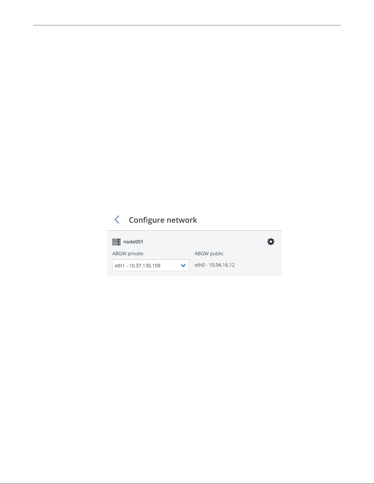
5. Make sure the correct network interface is selected in the drop-down list. Click NEXT.
If necessary, click the cogwheel icon and configure node’s network interfaces on the Network
Configuration screen.
6. On the Volume Parameters tab, select the desired tier, failure domain, and data redundancy mode.
8
Page 12

Chapter 4. Connecting Acronis Backup Software to Storage Backends via Backup Gateway
Redundancy by replication is not supported for Backup Gateway.
You can later change the erasure coding mode on the Backup > Parameters panel.
7. On the DNS Configuration tab, specify the external DNS name for this gateway, e.g,
backupgateway.example.com. Make sure that each node running the gateway service has a port open for
outgoing Internet connections and incoming connections from your Acronis backup software. Backup
agents will use this address and port to upload the backup data.
Important: Configure your DNS server according to the example suggested in the admin panel.
Important: Each time you change nodes in the Backup Gateway cluster, adjust the DNS settings
accordingly.
9
Page 13

Chapter 4. Connecting Acronis Backup Software to Storage Backends via Backup Gateway
Click Next.
8. On the Register in backup software pane, specify the following information for your Acronis product:
• In Address, specify the address of the Acronis Backup Cloud management portal (e.g.,
https://cloud.acronis.com/) or the hostname/IP address and port of the Acronis Backup Advanced
management server (e.g., http://192.168.1.2:9877).
• In Account, specify the credentials of a partner account in the cloud or of an organization
administrator on the local management server.
9. Finally, click DONE.
4.2 Connecting to External NFS Shares via Backup Gateway
Take note of these limitations:
• Acronis Cyber Infrastructure does not provide data redundancy on top of NFS volumes. Depending on
the implementation, NFS shares may use their own hardware or software redundancy.
• In the current version of Acronis Cyber Infrastructure, only one cluster node may store backups on an
10
Page 14

Chapter 4. Connecting Acronis Backup Software to Storage Backends via Backup Gateway
NFS volume.
Before you proceed, make sure that:
1. The NFS share has enough space for backups.
2. Each NFS export is used by only one gateway. In particular, do not configure two Acronis Cyber
Infrastructure installations to use the same NFS export for backup storage.
To set up Backup Gateway, do the following:
1. On the INFRASTRUCTURE > Networks screen, make sure that the ABGW private and ABGW public
traffic types are added to your networks.
2. In the left menu, click STORAGE SERVICES > Backup storage.
3. Select the node(s) to run the gateway services on and click Create gateway in the right menu.
4. Select Network File System as storage type.
5. Make sure the correct network interface is selected in the drop-down list. Click NEXT.
If necessary, click the cogwheel icon and configure node’s network interfaces on the Network
Configuration screen.
6. On the Volume Parameters tab, specify the hostname or IP address of the NFS share as well as the
export name. Click NEXT.
11
Page 15

Chapter 4. Connecting Acronis Backup Software to Storage Backends via Backup Gateway
7. On the DNS Configuration tab, specify the external DNS name for this gateway, e.g,
backupgateway.example.com. Make sure that each node running the gateway service has a port open for
outgoing Internet connections and incoming connections from your Acronis backup software. Backup
agents will use this address and port to upload the backup data.
Important: Configure your DNS server according to the example suggested in the admin panel.
Important: Each time you change nodes in the Backup Gateway cluster, adjust the DNS settings
accordingly.
12
Page 16

Chapter 4. Connecting Acronis Backup Software to Storage Backends via Backup Gateway
Click Next.
8. On the Register in backup software pane, specify the following information for your Acronis product:
• In Address, specify the address of the Acronis Backup Cloud management portal (e.g.,
https://cloud.acronis.com/) or the hostname/IP address and port of the Acronis Backup Advanced
management server (e.g., http://192.168.1.2:9877).
• In Account, specify the credentials of a partner account in the cloud or of an organization
administrator on the local management server.
9. Finally, click DONE.
4.3 Connecting to Public Cloud Storage via Backup Gateway
With Backup Gateway, you can have Acronis Backup Cloud or Acronis Backup Advanced store backups in a
number of public clouds: Amazon S3, IBM Cloud, Alibaba Cloud, IIJ, Cleversafe, Microsoft Azure, Swift object
storage, Softlayer (Swift), Google Cloud Platform, Wasabi, as well as solutions using S3 with the older
AuthV2-compatible authentication methods. However, compared to the local storage cluster, storing backup
data in a public cloud increases the latency of all I/O requests to backups and reduces performance. For this
13
Page 17

Chapter 4. Connecting Acronis Backup Software to Storage Backends via Backup Gateway
reason, it is recommended to use the local storage cluster as storage backend.
Since backups are cold data with specific access rights, it is cost-efficient to use storage classes that are
intended for long-term storage of infrequently accessed data. The recommended storage classes include the
following:
• Infrequent Access for Amazon S3
• Cool Blob Storage for Microsoft Azure
• Nearline and Coldline Storage for Google Cloud Platform
Note that real data storage costs may be 10-20% higher due to additional fees for operations like data
retrieval and early deletion.
4.3.1 Important Requirements and Restrictions
• When working with public clouds, Backup Gateway uses the local storage as the staging area as well as
to keep service information. It means that the data to be uploaded to a public cloud is first stored
locally and only then sent to the destination. For this reason, it is vital that the local storage is persistent
and redundant so the data does not get lost. There are multiple ways to ensure the persistence and
redundancy of local storage. You can deploy Backup Gateway on multiple cluster nodes and select a
good redundancy mode. If Acronis Cyber Infrastructure with the gateway is deployed on a single
physical node, you can make the local storage redundant by replicating it among local disks. If Acronis
Cyber Infrastructure with the gateway is deployed in a virtual machine, make sure it is made redundant
by the virtualization solution it runs on.
• Make sure the local storage cluster has plenty of logical space for staging. For example, if you perform
backup daily, provide enough space for at least 1.5 days’ worth of backups. If the daily backup total is
2TB, provide at least 3TB of logical space. The required raw storage will vary depending on the encoding
mode: 9TB (3TB per node) in the 1+2 mode, 5TB (1TB per node) in the 3+2 mode, etc.
• If you are to store backups in an Amazon S3 cloud, keep in mind that Backup Gateway may sometimes
block access to such backups due to the eventual consistency of Amazon S3. It means that Amazon S3
may occasionally return stale data as it needs time to render the most recent version of the data
accessible. Backup Gateway detects such delays and protects backup integrity by blocking access until
the cloud updates.
• Use a separate object container for each Backup Gateway cluster.
14
Page 18
Chapter 4. Connecting Acronis Backup Software to Storage Backends via Backup Gateway
4.3.2 Setting Up Backup Gateway
Before you proceed, make sure that the destination storage has enough space for backups.
To set up Backup Gateway, do the following:
1. On the INFRASTRUCTURE > Networks screen, make sure that the ABGW private and ABGW public
traffic types are added to your networks.
2. In the left menu, click STORAGE SERVICES > Backup storage.
3. Select the node(s) to run the gateway services on and click Create gateway in the right menu.
4. Select Public Cloud as storage type.
5. Make sure the correct network interface is selected in the drop-down list. Click NEXT.
If necessary, click the cogwheel icon and configure node’s network interfaces on the Network
Configuration screen.
6. On the Public cloud parameters pane, do the following:
1. Select a public cloud provider. If your provider is S3-compatible but not in the list, try AuthV2
compatible.
2. Depending on the provider, specify Region, Authentication (keystone) URL, or Endpoint URL.
3. In case of Swift object storage, specify the authentication protocol version and attributes required
by it.
4. Specify user credentials. In case of Google Cloud, select a JSON file with keys to upload.
5. Specify the folder (bucket, container) to store backups in. The folder must be writeable.
Use a separate object container for each Backup Gateway cluster.
Click NEXT.
15
Page 19

Chapter 4. Connecting Acronis Backup Software to Storage Backends via Backup Gateway
7. On the Register in backup software pane, specify the following information for your Acronis product:
• In Address, specify the address of the Acronis Backup Cloud management portal (e.g.,
https://cloud.acronis.com/) or the hostname/IP address and port of the Acronis Backup Advanced
management server (e.g., http://192.168.1.2:9877).
• In Account, specify the credentials of a partner account in the cloud or of an organization
administrator on the local management server.
8. Finally, click DONE.
16
Page 20

CHAPTER 5
Updating Certificate for Backup
Gateway
When you register a Backup Gateway in Acronis Backup Cloud or Acronis Backup Advanced, they exchange
certificates that are valid for one year. One and a half months before expiration, you will be alerted about the
expiring certificate in the admin panel. To update the certificate, you need to connect to your backup
software and renew the certificate. Do the following:
1. On the STORAGE SERVICES > Backup storage screen, click Update certificate.
2. On the Connect to backup software pane, specify the following information for your Acronis product:
• In Address, specify the address of the Acronis Backup Cloud management portal (e.g.,
https://cloud.acronis.com/) or the hostname/IP address and port of the Acronis Backup Advanced
management server (e.g., http://192.168.1.2:9877).
• In Account, specify the credentials of a partner account in the cloud or of an organization
administrator on the local management server.
17
Page 21

Chapter 5. Updating Certificate for Backup Gateway
3. Click NEXT.
4. On all nodes included into the ABGW cluster, restart the service:
# systemctl restart vstorage-abgw
18
Page 22

CHAPTER 6
Re-registering Backup Gateway in a New Acronis Backup Advanced
To switch a configured Backup Gateway to a different Acronis Backup Advanced instance, re-register the
gateway with that instance. To do this:
1. On the STORAGE SERVICES > Backup storage screen, click Re-register.
2. On the Re-registration in Acronis Backup tab, specify the following:
• In Address, specify the hostname/IP address of the target management server and the port 9877
(e.g., http://192.168.1.2:9877). Note that the address must be provided using the HTTP protocol,
not HTTPS.
• In Account, specify the credentials of the management server administrator account.
3. Click DONE.
19
Page 23

CHAPTER 7
Migrating Backups from Older Solutions
By means of Backup Gateway, you can migrate backups from Acronis Storage 1.5 and Acronis Storage
Gateway 1.6 and 1.7 to a storage backend of your choice: the local storage cluster, external NFS, or public
cloud.
Migration to NFS backends is not available, however, if multiple nodes are selected as Backup Gateway.
Important: Before you proceed, make sure that the destination storage has enough space for both existing
and new backups.
The migration procedure can be described as follows:
1. Root credentials for SSH access to the chosen source storage are provided to Backup Gateway.
2. Backup Gateway sets up a proxy on the source storage that starts redirecting requests incoming from
Acronis Backup Agents from the source storage to Backup Gateway.
3. Backup Gateway starts relocating backups to the chosen storage backend. The data that remains to be
migrated is shown in the Migration Backlog section on the Backup Gateway Overview screen. When
the backlog empties, all data has been migrated.
After the migration has started, the data of new and incremental backups is stored on the destination
storage. Backups from the source storage are pulled in the background. The entire process is
transparent to backup agents, which continue working uninterrupted.
4. To be able to dispose of the source storage after migration completes, requests from Acronis Backup
20
Page 24

Chapter 7. Migrating Backups from Older Solutions
Agents are directed straight to Backup Gateway, bypassing the proxy on the source storage. Steps that
you need to take depend on how the source storage is registered in Acronis Backup Cloud: under the IP
address or DNS name.
• If the source storage is already registered under the DNS name, you need to change the IP address
behind it to those of the Backup Gateway nodes.
• If the source storage is registered under the IP address, it is strongly recommended to re-register
Backup Gateway in Acronis Backup Cloud under a DNS name that resolves into the IP addresses of
Backup Gateway nodes. Using a DNS name will provide a smoother transition and you will not
need to reconfigure Acronis Backup Cloud even if you change nodes in the Backup Gateway (you
will still need to adjust the IP addresses behind the DNS name accordingly).
Alternatively, if you do not want to use a DNS name, you need to wait for the migration to
complete, shut down both the source and destination machines, and reconfigure your network so
that the public interface of the destination machine gets the IP address of the source machine.
The concrete steps that you need to perform in the admin panel to initiate backup migration are described in
the next subsections.
7.1 Migrating Backups from Acronis Storage
1.5
1. Update all Acronis Storage 1.5 nodes to version 1.5.65665 or newer as earlier versions are not eligible
for migration. To do this, log in to the Acronis Storage web console, proceed to SETTINGS > Software
Update, upload the latest ISO image, and click Update.
2. Log in to the new storage cluster and on the STORAGE SERVICES > Backup storage > NODES screen,
select one or more nodes and click Migrate.
3. Select Acronis Storage 1.5 and click NEXT.
4. Specify the DNS name of the source storage registered in Acronis Backup Cloud and click NEXT.
21
Page 25

Chapter 7. Migrating Backups from Older Solutions
5. Provide the credentials for the cloud management portal of the Acronis Backup Cloud installation that
the source storage is registered in and click NEXT.
6. Enable SSH access on all FES nodes of Acronis Storage 1.5 as instructed and click NEXT.
7. Map the public IP addresses of FES nodes accessible via SSH to their private IP addresses and click
NEXT. This step is required to access FES nodes via SSH through tunnels.
8. Choose a storage type to create a gateway to one of the destinations:
• local storage cluster
22
Page 26

Chapter 7. Migrating Backups from Older Solutions
• external NFS
• public cloud
9. Make sure the correct network interface is selected in the drop-down list. Click NEXT.
If necessary, click the cogwheel icon and configure node’s network interfaces on the Network
Configuration screen.
10. Configure the destination storage backend:
• For a storage cluster, select the desired tier, failure domain, and redundancy mode.
• For NFS, specify a hostname or IP address, an export name and path, and choose the NFS version.
• For a public cloud, select a public cloud provider, specify credentials, and the name of the folder
(bucket, container).
Use a separate object container for each Backup Gateway cluster.
23
Page 27

Chapter 7. Migrating Backups from Older Solutions
Click NEXT.
11. Review the source and destination storages and click PROCEED.
12. On the next panel, follow the instructions to point the source storage DNS name to the IP addresses of
your new storage cluster. Having updated the DNS configuration, wait for 24 hours for all backup
agents to cache the new IP addresses. Until this happens, the START MIGRATION button will be
disabled. After all backup agents have been rerouted to the new cluster, the button will become
enabled and you can click it to start migration.
24
Page 28

Chapter 7. Migrating Backups from Older Solutions
Depending on data size, migration may take as long as several days.
7.2 Migrating Backups from Acronis Storage Gateway 1.6 and 1.7 (NFS)
1. Disable the firewall or explicitly open TCP port 44446 on the source Acronis Storage Gateway.
• To disable the firewall, run
# systemctl stop firewalld
25
Page 29

Chapter 7. Migrating Backups from Older Solutions
• To open TCP port 44446 in the firewall, do the following:
1. Find out the zone where port 44445 is open:
# firewall-cmd --list-all-zones | grep active
mix_eth0 (active)
2. Add the required port to the same zone:
# firewall-cmd --zone=mix_eth0 --permanent --add-port=44446/tcp
# firewall-cmd --reload
2. In the admin panel of the ABGW node, proceed to STORAGE SERVICES > Backup storage > NODES,
select the node(s) to run the gateway services on, and click Migrate.
3. Select the source storage version and click NEXT.
4. Specify the connection details for the source storage and click NEXT.
5. Provide the credentials for the cloud management portal of the Acronis Backup Cloud installation that
the source storage is registered in and click NEXT.
6. If the source storage is registered in Acronis Backup Cloud under an IP address, you will see the DNS
configuration screen. On it, click RE-REGISTER WITH DNS and specify the source storage DNS name
(recommended, see above). Or, if you want to keep using the IP address, click PROCEED WITH IP.
If you specified a DNS name, configure your DNS server according to the suggested example.
26
Page 30

Chapter 7. Migrating Backups from Older Solutions
Important: Each time you change nodes in the Backup Gateway cluster, adjust the DNS settings
accordingly.
7. Choose a storage type to create a gateway to one of the destinations:
• local storage cluster
• external NFS
• public cloud
8. Make sure the correct network interface is selected in the drop-down list. Click NEXT.
If necessary, click the cogwheel icon and configure node’s network interfaces on the Network
Configuration screen.
9. Configure the destination storage backend:
• For a storage cluster, select the desired tier, failure domain, and redundancy mode.
• For NFS, specify a hostname or IP address, an export name and path, and choose the NFS version.
• For a public cloud, select a public cloud provider, specify credentials, and the name of the folder
(bucket, container).
Use a separate object container for each Backup Gateway cluster.
27
Page 31

Chapter 7. Migrating Backups from Older Solutions
Click NEXT.
10. Review the source and destination storages and click START MIGRATION.
Depending on data size, migration may take as long as several days.
28
Page 32

CHAPTER 8
Monitoring Backup Gateway
After you create a Backup Gateway, you can monitor it on the STORAGE SERVICES > Backup storage >
OVERVIEW screen. The charts show the following information:
• the performance of Backup Gateway services
• the geo-replication speed and backlog (the amount of data waiting to be replicated)
• object storage speed and backlog (the amount of data waiting to be uploaded to public cloud)
• migration speed and backlog (the amount of data waiting to be migrated)
• how many files are left in migration queue
If you migrate backups from Acronis Storage 1.5 or 1.7, migration backlog will be larger than the amount of
data on the source storage. The reason is that Acronis Storage versions prior to 2.x use the old backup (FES)
protocol that sends more data over network. The difference between source data size and backlog also very
much depends on the retention policy utilized by the backup solution. Despite this, the resulting space
occupied by migrated data on the destination will be similar to that on the source.
If backlogs do not decrease over time, it means the data cannot be replicated, migrated, or uploaded fast
enough. The reason may be insufficient network transfer speed, and you may need to check or upgrade your
network.
29
Page 33

Chapter 8. Monitoring Backup Gateway
30
Page 34

CHAPTER 9
Releasing Nodes from Backup Gateway
Backup Gateway is meant to provide access to one specific storage backend. If you need to switch the
backend, e.g., from a public cloud to a local storage cluster or one public cloud bucket to another, you need
to delete the Backup Gateway by releasing all its nodes and create a new one.
When the Backup Gateway is deleted, it is also unregistered from your Acronis backup software, which loses
access to the storage backend.
Do the following to release the last node in the gateway:
1. On the STORAGE SERVICES > Backup storage > NODES screen, select the node and click Release.
2. On the Unregister from backup software panel, choose one of the following:
• Graceful release (recommended, see note below). Releases the node, deletes the Backup
Gateway and unregisters it from your Acronis backup software.
• Force release. Releases the node, deletes the Backup Gateway but does not unregister it from
your Acronis backup software.
Important: Choose this option only if you are sure that the gateway has already been
unregistered from your Acronis backup software. Otherwise, you will need to register a new
gateway in your Acronis backup software and for that you will need to delete and recreate not just
the Backup Gateway but also the entire storage cluster.
31
Page 35

Chapter 9. Releasing Nodes from Backup Gateway
3. Specify the credentials of your administrator account in your Acronis backup software and click NEXT.
In case the release is forced, simply click NEXT.
32
 Loading...