

Page 1

Aspire Z5700/Z5710 Series
Service Guide
Service guide files and updates are available
on the ACER/CSD web; for more information,
please refer to http://csd.acer.com.tw
PRINTED IN TAIWAN
Page 2

Revision History
Please refer to the table below for the updates made on this service guide.
Date Chapter Updates
II
Page 3

Copyright
Copyright © 2010 by Acer Incorporated. All rights reserved. No part of this publication may be reproduced,
transmitted, transcribed, stored in a retrieval system, or translated into any language or computer language, in
any form or by any means, electronic, mechanical, magnetic, optical, chemical, manual or otherwise, without
the prior written permission of Acer Incorporated.
Disclaimer
The information in this guide is subject to change without notice.
Acer Incorporated makes no representations or warranties, either expressed or implied, with respect to the
contents hereof and specifically disclaims any warranties of merchantability or fitness for any particular
purpose. Any Acer Incorporated software described in this manual is sold or licensed "as is". Should the
programs prove defective following their purchase, the buyer (and not Acer Incorporated, its distributor, or its
dealer) assumes the entire cost of all necessary servicing, repair, and any incidental or consequential
damages resulting from any defect in the software.
Acer is a registered trademark of Acer Corporation.
Intel is a registered trademark of Intel Corporation.
Other brand and product names are trademarks and/or registered trademarks of their respective holders.
III
Page 4

Conventions
The following conventions are used in this manual:
SCREEN MESSAGES Denotes actual messages that
appear on screen.
NOTE Gives bits and pieces of additional
information related to the current
topic.
WARNING Alerts you to any damage that might
result from doing or not doing
specific actions.
CAUTION Gives precautionary measures to
avoid possible hardware or software
problems.
IMPORTANT Reminds you to do specific actions
relevant to the accomplishment of
procedures.
NOTE: This symbol where placed in the Service Guide designates a compo nent tha t s hould
be recycled according to the local regulations.
IV
Page 5

Preface
Before using this information and the product it supports, please read the following general information.
1. This Service Guide provides you with all technical information relating to the BASIC CONFIGURATION
decided for Acer's "global" product offering. To better fit local market requirements and enhance product
competitiveness, your regional office MAY have decided to extend the functionality of a machine (e.g.
add-on card, modem, or extra memory capability). These LOCALIZED FEATURES will NOT be covered
in this generic service guide. In such cases, please contact your regional offices or the responsible
personnel/channel to provide you with further technical details.
2. Please note WHEN ORDERING FRU PARTS, that you should check the most up-to-date information
available on your regional web or channel. If, for whatever reason, a part number change is made, it will
not be noted in the printed Service Guide. For ACER-AUTHORIZED SERVICE PROVIDERS, your Acer
office may have a DIFFERENT part number code to those given in the FRU list of this printed Service
Guide. You MUST use the list provided by your regional Acer office to order FRU parts for repair and
service of customer machines.
V
Page 6

VI
Page 7

Table of Contents
System Specifications 1
Features . . . . . . . . . . . . . . . . . . . . . . . . . . . . . . . . . . . . . . . . . . . . . . . . . . . . . . . . . . . .1
System Block Diagram . . . . . . . . . . . . . . . . . . . . . . . . . . . . . . . . . . . . . . . . . . . . . . . . .6
Your Computer tour . . . . . . . . . . . . . . . . . . . . . . . . . . . . . . . . . . . . . . . . . . . . . . . . . . . . . . . . . . . 7
Front View . . . . . . . . . . . . . . . . . . . . . . . . . . . . . . . . . . . . . . . . . . . . . . . . . . . . . . .7
Right View . . . . . . . . . . . . . . . . . . . . . . . . . . . . . . . . . . . . . . . . . . . . . . . . . . . . . . .8
Left View . . . . . . . . . . . . . . . . . . . . . . . . . . . . . . . . . . . . . . . . . . . . . . . . . . . . . . . .9
Rear View . . . . . . . . . . . . . . . . . . . . . . . . . . . . . . . . . . . . . . . . . . . . . . . . . . . . . .10
Using the Keyboard . . . . . . . . . . . . . . . . . . . . . . . . . . . . . . . . . . . . . . . . . . . . . . . . . .11
Windows Keys . . . . . . . . . . . . . . . . . . . . . . . . . . . . . . . . . . . . . . . . . . . . . . . . . . . . . . . . . 12
Hardware Specifications and Configurations . . . . . . . . . . . . . . . . . . . . . . . . . . . . . . .13
System Utilities 23
BIOS Setup Utility . . . . . . . . . . . . . . . . . . . . . . . . . . . . . . . . . . . . . . . . . . . . . . . . . . . .23
Navigating the BIOS Utility . . . . . . . . . . . . . . . . . . . . . . . . . . . . . . . . . . . . . . . . .23
CMOS Setup Utility . . . . . . . . . . . . . . . . . . . . . . . . . . . . . . . . . . . . . . . . . . . . . . .24
Product Information . . . . . . . . . . . . . . . . . . . . . . . . . . . . . . . . . . . . . . . . . . . . . . .25
Standard CMOS Features . . . . . . . . . . . . . . . . . . . . . . . . . . . . . . . . . . . . . . . . .26
Advanced BIOS Features . . . . . . . . . . . . . . . . . . . . . . . . . . . . . . . . . . . . . . . . . .27
Advanced Chipset Features . . . . . . . . . . . . . . . . . . . . . . . . . . . . . . . . . . . . . . . .28
Integrated Peripherals . . . . . . . . . . . . . . . . . . . . . . . . . . . . . . . . . . . . . . . . . . . . .29
Power Management Features . . . . . . . . . . . . . . . . . . . . . . . . . . . . . . . . . . . . . . .30
PC Health . . . . . . . . . . . . . . . . . . . . . . . . . . . . . . . . . . . . . . . . . . . . . . . . . . . . . .31
Frequency Voltage Control . . . . . . . . . . . . . . . . . . . . . . . . . . . . . . . . . . . . . . . . .32
BIOS Security Features . . . . . . . . . . . . . . . . . . . . . . . . . . . . . . . . . . . . . . . . . . .33
BIOS Flash Utilities . . . . . . . . . . . . . . . . . . . . . . . . . . . . . . . . . . . . . . . . . . . . . . . . . . .36
DOS Flash Utility . . . . . . . . . . . . . . . . . . . . . . . . . . . . . . . . . . . . . . . . . . . . . . . . .37
Win Flash Utility . . . . . . . . . . . . . . . . . . . . . . . . . . . . . . . . . . . . . . . . . . . . . . . . .38
Using DMI Tools . . . . . . . . . . . . . . . . . . . . . . . . . . . . . . . . . . . . . . . . . . . . . . . . .39
Machine Disassembly and Replacement 40
Disassembly Requirements . . . . . . . . . . . . . . . . . . . . . . . . . . . . . . . . . . . . . . . . . . . .40
General Information . . . . . . . . . . . . . . . . . . . . . . . . . . . . . . . . . . . . . . . . . . . . . . . . . .40
Pre-disassembly Instructions . . . . . . . . . . . . . . . . . . . . . . . . . . . . . . . . . . . . . . .40
Disassembly Process . . . . . . . . . . . . . . . . . . . . . . . . . . . . . . . . . . . . . . . . . . . . . . . . .42
Disassembly Flowchart . . . . . . . . . . . . . . . . . . . . . . . . . . . . . . . . . . . . . . . . . . . .42
Removing the RAM Covers . . . . . . . . . . . . . . . . . . . . . . . . . . . . . . . . . . . . . . . .44
Removing the RAM . . . . . . . . . . . . . . . . . . . . . . . . . . . . . . . . . . . . . . . . . . . . . . .46
Removing the Rear Covers . . . . . . . . . . . . . . . . . . . . . . . . . . . . . . . . . . . . . . . . .47
Removing the Back Cover . . . . . . . . . . . . . . . . . . . . . . . . . . . . . . . . . . . . . . . . .48
Removing the Hinge . . . . . . . . . . . . . . . . . . . . . . . . . . . . . . . . . . . . . . . . . . . . . .50
Removing the Mainboard Shielding . . . . . . . . . . . . . . . . . . . . . . . . . . . . . . . . . .51
Removing the Hard Disk Drive . . . . . . . . . . . . . . . . . . . . . . . . . . . . . . . . . . . . . .55
Removing the Power Supply . . . . . . . . . . . . . . . . . . . . . . . . . . . . . . . . . . . . . . . .58
Removing the Touchscreen Control Board . . . . . . . . . . . . . . . . . . . . . . . . . . . . .59
Removing the Card Reader Board . . . . . . . . . . . . . . . . . . . . . . . . . . . . . . . . . . .62
Removing the Audio Board . . . . . . . . . . . . . . . . . . . . . . . . . . . . . . . . . . . . . . . . .63
Removing the ODD Eject Board . . . . . . . . . . . . . . . . . . . . . . . . . . . . . . . . . . . . .65
Removing the ODD . . . . . . . . . . . . . . . . . . . . . . . . . . . . . . . . . . . . . . . . . . . . . . .67
. . . . . . . . . . . . . . . . . . . . . . . . . . . . . . . . . . . . . . . . . . . . . . . . . . . . . . . . . . . . . .69
Removing the Inverter Board . . . . . . . . . . . . . . . . . . . . . . . . . . . . . . . . . . . . . . .70
Removing the Home Button Board . . . . . . . . . . . . . . . . . . . . . . . . . . . . . . . . . . .73
Removing the Camera Module . . . . . . . . . . . . . . . . . . . . . . . . . . . . . . . . . . . . . .75
Removing the TV Tuner Module . . . . . . . . . . . . . . . . . . . . . . . . . . . . . . . . . . . . .77
Removing the Wireless LAN Module . . . . . . . . . . . . . . . . . . . . . . . . . . . . . . . . .79
VII
Page 8

Table of Contents
Removing the Thermal Module . . . . . . . . . . . . . . . . . . . . . . . . . . . . . . . . . . . . . .81
Removing the Fans . . . . . . . . . . . . . . . . . . . . . . . . . . . . . . . . . . . . . . . . . . . . . . .82
Removing the CPU . . . . . . . . . . . . . . . . . . . . . . . . . . . . . . . . . . . . . . . . . . . . . . .84
Removing the Mainboard . . . . . . . . . . . . . . . . . . . . . . . . . . . . . . . . . . . . . . . . . .85
Removing the Frame . . . . . . . . . . . . . . . . . . . . . . . . . . . . . . . . . . . . . . . . . . . . .89
Removing the LCD Panel . . . . . . . . . . . . . . . . . . . . . . . . . . . . . . . . . . . . . . . . . .95
Removing the Bluetooth Module . . . . . . . . . . . . . . . . . . . . . . . . . . . . . . . . . . . . .97
Removing the IR Board . . . . . . . . . . . . . . . . . . . . . . . . . . . . . . . . . . . . . . . . . . . .98
Removing the Home Button Board . . . . . . . . . . . . . . . . . . . . . . . . . . . . . . . . . .100
Removing the USB Board . . . . . . . . . . . . . . . . . . . . . . . . . . . . . . . . . . . . . . . . .101
Removing the Speakers . . . . . . . . . . . . . . . . . . . . . . . . . . . . . . . . . . . . . . . . . .103
Removing the Antennas . . . . . . . . . . . . . . . . . . . . . . . . . . . . . . . . . . . . . . . . . .104
Reassembly Procedure . . . . . . . . . . . . . . . . . . . . . . . . . . . . . . . . . . . . . . . . . . . . . .105
Replacing the Antennas . . . . . . . . . . . . . . . . . . . . . . . . . . . . . . . . . . . . . . . . . .105
Replacing the Speakers . . . . . . . . . . . . . . . . . . . . . . . . . . . . . . . . . . . . . . . . . .106
Replacing the USB Board . . . . . . . . . . . . . . . . . . . . . . . . . . . . . . . . . . . . . . . . .107
Replacing the IR Board . . . . . . . . . . . . . . . . . . . . . . . . . . . . . . . . . . . . . . . . . . .108
Replacing the Home Button Board . . . . . . . . . . . . . . . . . . . . . . . . . . . . . . . . . .109
Replacing the Bluetooth Module . . . . . . . . . . . . . . . . . . . . . . . . . . . . . . . . . . . .110
Replacing the LCD Panel in the Frame . . . . . . . . . . . . . . . . . . . . . . . . . . . . . .111
Replacing the Frame . . . . . . . . . . . . . . . . . . . . . . . . . . . . . . . . . . . . . . . . . . . . .113
Replacing the Mainboard . . . . . . . . . . . . . . . . . . . . . . . . . . . . . . . . . . . . . . . . .117
Replacing the CPU . . . . . . . . . . . . . . . . . . . . . . . . . . . . . . . . . . . . . . . . . . . . . .120
Replacing the Fans . . . . . . . . . . . . . . . . . . . . . . . . . . . . . . . . . . . . . . . . . . . . . .121
Replacing the Thermal Module . . . . . . . . . . . . . . . . . . . . . . . . . . . . . . . . . . . . .123
Replacing the WLAN Module . . . . . . . . . . . . . . . . . . . . . . . . . . . . . . . . . . . . . .124
Replacing the TV Tuner Module . . . . . . . . . . . . . . . . . . . . . . . . . . . . . . . . . . . .125
Replacing the Camera Module . . . . . . . . . . . . . . . . . . . . . . . . . . . . . . . . . . . . .126
Replacing the Power Board . . . . . . . . . . . . . . . . . . . . . . . . . . . . . . . . . . . . . . .128
Replacing the Inverter Board . . . . . . . . . . . . . . . . . . . . . . . . . . . . . . . . . . . . . .129
Replacing the ODD Module . . . . . . . . . . . . . . . . . . . . . . . . . . . . . . . . . . . . . . .132
Replacing the ODD Eject Board . . . . . . . . . . . . . . . . . . . . . . . . . . . . . . . . . . . .134
Replacing the Audio Board . . . . . . . . . . . . . . . . . . . . . . . . . . . . . . . . . . . . . . . .135
Connect the Card Reader Board . . . . . . . . . . . . . . . . . . . . . . . . . . . . . . . . . . .136
Replacing the Touchscreen Board . . . . . . . . . . . . . . . . . . . . . . . . . . . . . . . . . .137
Replacing the Power Supply . . . . . . . . . . . . . . . . . . . . . . . . . . . . . . . . . . . . . . .139
Replacing the HDD . . . . . . . . . . . . . . . . . . . . . . . . . . . . . . . . . . . . . . . . . . . . . .140
Replacing the Mainboard Shielding . . . . . . . . . . . . . . . . . . . . . . . . . . . . . . . . .142
Replacing the Hinge . . . . . . . . . . . . . . . . . . . . . . . . . . . . . . . . . . . . . . . . . . . . .146
Replacing the Rear Cover . . . . . . . . . . . . . . . . . . . . . . . . . . . . . . . . . . . . . . . . .147
Replacing the Rear Covers . . . . . . . . . . . . . . . . . . . . . . . . . . . . . . . . . . . . . . . .149
Replacing the RAM . . . . . . . . . . . . . . . . . . . . . . . . . . . . . . . . . . . . . . . . . . . . . .151
Replacing the Rear Covers . . . . . . . . . . . . . . . . . . . . . . . . . . . . . . . . . . . . . . . .152
Troubleshooting 154
Common Problems . . . . . . . . . . . . . . . . . . . . . . . . . . . . . . . . . . . . . . . . . . . . . . . . . .154
ODD Failure . . . . . . . . . . . . . . . . . . . . . . . . . . . . . . . . . . . . . . . . . . . . . . . . . . .155
Wireless Failure . . . . . . . . . . . . . . . . . . . . . . . . . . . . . . . . . . . . . . . . . . . . . . . .158
Camera Failure . . . . . . . . . . . . . . . . . . . . . . . . . . . . . . . . . . . . . . . . . . . . . . . . .159
Speaker Failure . . . . . . . . . . . . . . . . . . . . . . . . . . . . . . . . . . . . . . . . . . . . . . . . .160
LCD Failure . . . . . . . . . . . . . . . . . . . . . . . . . . . . . . . . . . . . . . . . . . . . . . . . . . . .162
General Troubleshooting Issues . . . . . . . . . . . . . . . . . . . . . . . . . . . . . . . . . . . .164
Intermittent Problems . . . . . . . . . . . . . . . . . . . . . . . . . . . . . . . . . . . . . . . . . . . . . . . .167
Undetermined Problems . . . . . . . . . . . . . . . . . . . . . . . . . . . . . . . . . . . . . . . . . . . . . .167
POST Codes . . . . . . . . . . . . . . . . . . . . . . . . . . . . . . . . . . . . . . . . . . . . . . . . . . .168
VIII
Page 9

Table of Contents
Jumper and Connector Locations 175
Mainboard Top View . . . . . . . . . . . . . . . . . . . . . . . . . . . . . . . . . . . . . . . . . . . . . . . . .175
BIOS Recovery . . . . . . . . . . . . . . . . . . . . . . . . . . . . . . . . . . . . . . . . . . . . . . . . . . . . .176
FRU (Field Replaceable Unit) List 177
Exploded Diagrams . . . . . . . . . . . . . . . . . . . . . . . . . . . . . . . . . . . . . . . . . . . . . . . . .178
FRU List . . . . . . . . . . . . . . . . . . . . . . . . . . . . . . . . . . . . . . . . . . . . . . . . . . . . . . . . . .180
Model Definition and Configuration 188
Test Compatible Components 190
Online Support Information 192
Index 193
IX
Page 10

Table of Contents
X
Page 11

System Specifications
Features
Below is a brief summary of the computer’s many features:
Operating system
• Genuine Windows® 7 Home Premium (Touch Pack)
Processor
Z5710
• Intel® Core™ i7-860/i7-870 processor (8 MB L3 cache, 2.80/2.93 GHz, with Turbo Boost up to
3.46/3.60 GHz, DDR3 1066 MHz, 95 W), supporting Intel® EM64T Technology, Intel®
Virtualization Technology
• Intel® Core™ i5-750 processor (8 MB L3 cache, 2.66 GHz with Turbo Boost up to 3.20 GHz,
DDR3 1333 MHz, 95 W), supporting Intel® EM64T Technology, Intel® Virtualization Technology
Z5700/Z5710
• Intel® Core™ i5-650/i5-660/i5-670 processor (4 MB L3 cache, 3.20/3.33/3.46 GHz, DDR3 1333
MHz, 73 W), supporting Intel® EM64T Technology, Intel® Virtualization Technology, Intel® HD
graphics
• Intel® Core™ i5-661 processor (4 MB L3 cache, 3.33 GHz, DDR3 1333 MHz, 87 W), supporting
Intel® EM64T Technology, Intel® Virtualization Technology, Intel® HD graphics
• Intel® Core™ i3-530/i3-540 processor (4 MB L3 cache, 2.93/3.06 GHz , DDR3 1333 MHz, 73 W),
supporting Intel® EM64T Technology, Intel® Virtualization Technology, Intel® HD graphics
• Intel® Pentium® processor G6950 (3 MB L3 cache, 2.80GHz, DDR3 1066 MHz, 73W) supporting
Intel® EM64T Technology, Intel® Virtualization Technology
Chapter 1
Chipset
• Intel® H57 Express Chipset
Memory
• Dual-channel DDR3 1066/1333 MHz SDRAM support:
• Up to 2 GB per memory module
• Upgrade option with four unbuffered DIMM slots
Chapter 1 1
Page 12

Graphics
Z5710
• NVIDIA® GeForce® G210M with 512 MB of dedicated DDR3 VRAM, supporting NVIDIA®
• NVIDIA® GeForce® GT240M with 1 GB of dedicated DDR3 VRAM, supporting NVIDIA® CUDA™,
• Dual independent display support
• 16.7 million colors
• External resolution / refresh rates:
• MPEG-2/DVD, MPEG-4 decoding
• WMV9 (VC-1), H.264 (AVC), DivX® decoding
• HDMI™ (High-Definition Multimedia Interface) with HDCP (High-bandwidth Digital Content
Z5700
• Intel® HD Graphics with 1.70 GB of video memory, featuring:
CUDA™, PhysX™, PureVideo® HD technology, OpenEXR High Dynamic-Range (HDR)
technology, Shader Model 4.0, Microsoft® DirectX® 10.1, OpenGL® 3.0
PhysX™, PureVideo® HD technology, OpenEXR High Dynamic-Range (HDR) technology , Shader
Model 4.0, Microsoft® DirectX® 10.1, OpenGL® 3.0
• VGA port up to 2048 x 1536: 85 Hz
• HDMI™ port up to 1920 x 1200: 60 Hz
Protection) support
• Intel® Clear Video HD Technology, DVD upscaling
• MPEG-2, VC-1, AVC/H.264 decoding
• De-interlacing, sharpness detail, noise reduction, Film Mode detection, video scaling, panel
scalar
• Microsoft® DirectX® 10 support
• Intel® Dynamic Video Memory Technology 5.0 (Intel® DVMT 5.0) support
• VGA port resolution / refresh rate up to 2560 x 1600: 60 Hz4
Display
• 23" Full HD 1920 x 1080 pixel resolution, high brightness (300-nit), TFT LCD
• 16:9 aspect ratio
• 5 ms response time
• 16.7 million colors
• 1000:1 (ACM) contrast ratio
Touchscreen
• Integrated Windows® 7 compliant multi-touch capable optical solution
Hard drive
Hard disk drive
• 500/640/750 GB / 1 TB 7200 RPM
• 1/1.5/2 TB 5400 RPM
Solid state drive
• 80 GB (optional)
2 Chapter 1
Page 13

Optical drive
4X Blu-ray Disc™ Reader / DVD-Super Multi double-layer drive:
• Read: 48X CD-ROM, 48X CD-R, 48 CD-RW, 16X DVD-ROM, 16X DVD-R, 16X DVD+R, 8X DVDROM DL, 8X DVD-R DL, 8X DVD+R DL, 8X DVD-RW, 8X DVD+RW, 12X DVD-RAM, 6X BDROM, 6X BD-R, 2X BD-RE, 6X BD-ROM DL, 2X BD-R DL, 2X BD-RE DL
• Write: 48X CD-R, 10X CD-RW, 16X DVD-R, 16X DVD+R, 16X DVD-RW, 16X DVD+RW, 5X DVDRAM, 8X DVD+R DL, 8X DVD-R DL
8X DVD-Super Multi double-layer drive:
• Read: 48X CD-ROM, 48X CD-R, 48 CD-RW, 16X DVD-ROM, 16X DVD-R, 16X DVD+R, 8X DVDROM DL, 8X DVD-R DL, 8X DVD+R DL, 8X DVD-RW, 8X DVD+RW, 12X DVD-RAM
• Write: 48X CD-R, 10X CD-RW, 16X DVD-R, 16X DVD+R, 16X DVD-RW, 16X DVD+RW, 5X DVDRAM, 8X DVD+R DL, 8X DVD-R DL
Card reader
• Multi-in-1 card reader, supporting:
• MultiMediaCard (MMC)
• Secure Digital™ (SD) Card / SDHC™ Card
• Memory Stick™ / Memory Stick PRO Duo™ / Memory Stick PRO-HG Duo™
TV-tuner
Hybrid TV-tuner supporting worldwide analog/DVB-T (Digital Video Broadcasting-Terrestrial)
• TV-tuner I/O:
• AIO platform
•RF-in
Hybrid TV-tuner supporting worldwide analog and ATSC (Advanced Television Systems Committee)
• TV-tuner I/O:
• AIO platform
•RF-in
Digital TV-tuner supporting ISDB-T/BS/CS
• TV-tuner I/O:
• Tower platform
•RF-in
Hybrid TV-tuner supporting DMB-T/H (Digital Multimedia Broadcast-Terrestial/Handheld)
• TV-tuner I/O:
• AIO platform
•RF-in
Audio
• Integrated 5 W stereo speaker system
• High-definition audio support
Chapter 1 3
Page 14

Communication
•WLAN:
• 802.11 b/g Wi-Fi CERTIFIED™
• 802.11 b/g/n Wi-Fi CERTIFIED™
•WPAN:
• Bluetooth® 2.1 + EDR
•LAN:
• Gigabit Ethernet
• Built-in 1 MP high-def webcam with 1280 x 800 resolution image capture
• Built-in microphone
I/O ports
Side:
• Multi-in-1 card reader
• Two USB 2.0 ports
• High-definition headphone and microphone jacks
• Ambient light switch
• BCAS card Reader Slot (Japan only)
Rear:
• Four USB 2.0 ports
• Audio
• Headphone/speaker/line-out jack
• Microphone-in jack
• Line-in jack
•Video
• HDMI™ port with HDCP support
• Communication
• Ethernet (RJ-45) port
• TV-tuner
• IR blaster port (bundled with TV-tuner card)
• TV-tuner port (bundled with TV-tuner card)
Power Supply Unit
• Adapter
• 250 W
4 Chapter 1
Page 15

Software
• Productivity:
• Multimedia:
• Security:
• Entertainment
• Utilities
• Acer Touch Suite
• Adobe® Reader®
•eSobi™
• Microsoft® Office 2007 Trial with Microsoft® Works
• Microsoft® Touch Pack (Microsoft® Surface Globe/Microsoft® Surface Collage/Microsoft®
Surface Lagoon/Microsoft® Blackboard/Microsoft® Rebound/ Microsoft® Garden Pond)
• CyberLink® PowerCinema®
• CyberLink® YouCam®
• McAfee® Internet Security Suite 2009 Trial9
• MyWinLocker®
• Oberon TouchGames
• Acer eRecovery Management
Security
• Kensington lock slot
• Hardware and BIOS passwords
Dimensions and Weight
• 570 (W) x 484.0 (H) x 84.6 (D) mm
System Compliance
• PC 2001
• ENERGY STAR®
NOTE: The specifications listed above are for reference only. The exact configuration of your PC depends on
the model purchased.
Chapter 1 5
Page 16

System Block Diagram
Processor
Lynnfield/
64-bit/45nm
LGA1156
(37.5x37.5mm)
DMI
x4
Ibex Peak
PCH
PCIE 2.0 x16(PEG)
PECI
Clarkdale
FDI
(*1)
MXM CNN
Mobile PCI-E Module
(Graphics)
TYPE-A(or B) (285 pin)
LVDS Transmitter
Chrontel CH7308
LQFP64
SDVOB
LVDS
(27x27mm)
FCBGA951
SATA IISATA HDD(3.5")
SATA ODD
eSATA
2nd SATA HDD
SATA 0
SATA 1
SATA 2
SATA 3
USB 2.0TOUCH Screen
CAREMA with
BLUE TOOTH
SIDE USB x2
USB 8
USB 4
USB 2
USB 1,5
REAR USB x4
USB 0,9,11,13
USB 10
USB 12
AUDIO CODEC
ALC888S-VC2
LQFP48
AUDIO AMP
MAX9736BETJ+
QFN32
INT SPK
CNN
Head Phone &
MIC IN CONN
EC/KBC
ITE8512
LQFP128
FAN CTRL
FLASH
ROM
(CPU/MXM)
IR
RECEIVERIRBlaster
LPC
PCI-E x1 PCIE 5
GB LAN
Intel 82578DC
RJ45 CNN
CARD READER CNN
USB 3
(2.5" x SSD)
Azailia
Array MIC
Mini PCIE1
WLAN CNN
Mini PCIE2
TV Tuner CARD CNN
PCIE 2
PCIE 3
(Realtek RTS5159-GR)
USB 2.0
LCD Panel CNN
(23'' 16:10)
(34.5W)
LVDS
Inverter CONN
UMA
(Max 45W)
(6.5W)
(95W)
802.11 b/g/n 3G/WiMax
Samsung LTM230TT01
5.1 Channel
LineInLine
Out(1)
Line
Out(1)
Line
Out(1)
5.1 Channel
1Mb SPI
32.768KHz
System Ambient
Light Sensor
VRM 11.1
CPU Core
(3)
B-CAS CNN
DDR3 DIMM0
Dual channel DDR3
800/1066/1333MHz 1.5V
Channel A
Channel B
CN14
DDR3 DIMM0
CN18
DDR3 DIMM1
CN13
DDR3 DIMM1
CN17
8GB per channel
8GB per channel
CLOCK Generator
CK505
14.318MHz
32.768KHz
14.318MHz
25MHz
P3P3V_DUAL
VCC_CORE/VTT_CPU
P5V_STBY
ACIN
VCC5
VCC3
P1P05V_PCH
P12V
VREG_12V
DDRIII Power
P1P8V(SFR)
Fan CNN
RTC Battery
Reset Circuit
Brightness Control
LED Indicator
MAIN SW CNN
ISL6334
VTT_CPU
(No MXM option)
LEVEL SHIFT
TMDS
(Clarkdale option)
HDMI CN
(Clarkdale
option)
TMDS
TMDS
LEVEL SHIFT
(Lynnfield
option)
TMDS
6 Chapter 1
Page 17

Your Computer tour
This section describes port locations, indicators, and controls for the computer.
IMPORTANT:Your computer’s hardware options, port locations, and indicators may vary from this illustration.
Front View
No. Component Icon Description
1 Microphone Use to talk through when making Voice over
Internet Protocol (VoIP) calls.
2 HD webcam Use to let others see who they are communicati ng
with when making VoIP calls.
3 Display screen Also called Liquid-Crystal Display (LCD), displays
computer output.
4Acer
TouchPortal
5 Power Button Press this button to turn the power on or off.
Access and control some of the handy features of
your new computer.
You can also configure the power button to
operate in Standby/Resume mode or
Hibernate mode.
Chapter 1 7
Page 18

Right View
IMPORTANT:Your computer’s hardware options, port locations, and indicators may vary from this illustration.
No. Component Icon Description
1 Headphone jack
(white plug)
2 Microphone jack
(pink plug)
Plug powered, analog front speakers, an external amplifier, or
headphones into this jack.
Plug a microphone into this jack.
3 Illumination To ggle
Switch
4 Memory card
reader
5 Optical Disk Drive Use this drive to listen to audio CDs, install games and programs,
Insert a memory card from a digital camera, MP3 player, PDA,
cellular telephone, or other device into the memory card reader.
watch DVDs, and
store large files onto recordable discs (depending on drive type). This
drive may be
a CD, recordable CD, DVD, or recordable DVD.
8 Chapter 1
Page 19

Left View
IMPORTANT:Your computer’s hardware options, port locations, and indicators may vary from this illustration.
No. Component Icon Description
1 B-CAS reader Subscription service available for select models only.
2 USB 2.0 port Plug USB (Universal Serial Bus) devices (such as a USB external
drive, printer, scanner, camera, ke yboard, or mouse) into this port.
Chapter 1 9
Page 20
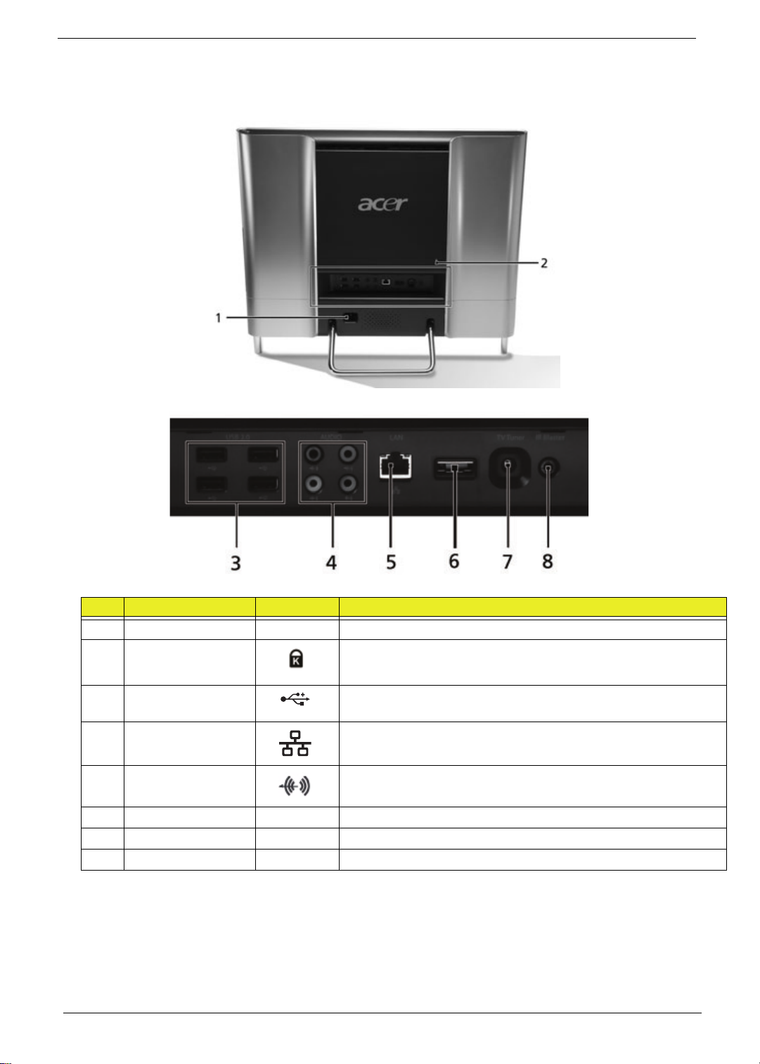
Rear View
IMPORTANT:Your computer’s hardware options, port locations, and indicators may vary from this illustration.
No. Component Icon Description
1 Power connector Plug the power cord into this connector.
2 Kensington™ lock
slot
3 USB ports Plug USB (Universal Serial Bus) devices (such as a USB printer,
4 Ethernet (network)
jack
5 Line-out/Speaker-
out jack
6 eSATA port Plug external hard drives into this connector.
7 TV Tuner Allows a TV Tuner to be connected to the system.
8 IR port Allows data transfer between the desktop and a mobile device.
Secure your computer to an object by connecting a Kensington
cable lock to this slot.
scanner, camera, keyboard, or mouse) into these ports.
Plug an Ethernet network cable or a device (such as a DSL or
cable modem for a broadband Internet connection) into this jack.
Plug an line output to an amplifier or entertainment system into
this jack for sound output.
10 Chapter 1
Page 21

Using the Keyboard
Windows key
Application
key
Navigation keys
Function keys
Audio playback keys
Fn key
The keyboard has several different types of keys and buttons as shown below.
Feature Icon Description
Function keys Press these keys to start program actions. Each program uses
different function keys for different purposes. See the program
documentation to find out more about the function key actions.
Audio playback keys Press these keys to play your audio files and to adjust the
volume.
Windows key Press this key to open the Windows Start menu.
This key can also be used in combination with other keys to
open utilities. See “Windows Keys” on page 12.
Fn key Press this key in combination with keys that have alternate
functions defined, such as the F9-F12 keys.
Press <Fn> + < > to increase the brightness of the display.
Press <Fn> + < > to decrease the brightness of the display.
Application key Press this key to access shortcut menus and help assistants in
Windows.
Navigation keys Press these keys to move the cursor and to copy, cut, and
paste objects.
Chapter 1 11
Page 22

Windows Keys
The keyboard has two keys that perform Windows-specific functions.
Key Description
Windows key Pressed alone, this key has the same effect as clicking on the Windows Start button;
it launches the Start menu. It can also be used with other keys to provide a variety of
functions:
<>: Open or close the S tart menu
<> + <D>: Display the desktop
<> + <E>: Open Windows Explore
<> + <F>: Search for a file or folder
<> + <G>: Cycle through Sidebar gadgets
<> + <L>: Lock your computer (if you are connected to a network domain), or
switch users (if you're not connected to a network domain)
<> + <M>: Minimizes all windows
<> + <R>: Open the Run dialog box
<> + <T>: Cycle through programs on the taskbar
<> + <U>: Open Ease of Access Center
<> + <X>: Open Windows Mobility Center
<> + <BREAK>: Display the System Properties dialog box
<> + <SHIFT+M>: Restore minimized windows to the desktop
<> + <TAB>: Cycle through programs on the taskbar by using Windows Flip 3-D
<> + <SPACEBAR>: Bring all gadgets to the front and select Windows Sidebar
Application
key
<CTRL> +
<CTRL> + <> + <TAB>: Use the arrow keys to cycle through programs on the
Note: Depending on your edition of Windows 7 some shortcuts may not function as
This key has the same effect as clicking the right mouse button; it opens the
application's context menu.
<> + <F>: Search for computers (if you are on a network)
taskbar by using Windows Flip 3-D
described.
12 Chapter 1
Page 23

Hardware Specifications and Configurations
Processor
Item Specification
CPU type* • Intel® Core2™ Duo processor
• Intel® Core™2 Quad processor
• Pentium® dual-core Processor
*Dependent on model shipped.
Chipset
Item Specification
Core logic
Features
CPU Package
CPU Core Voltage
Ibex Peak package H57
• FCBGA package
• Package size: 27mm x 27mm
• Ball Count: 951
• Ball pitch: 0.7mm
• PCI Express* Base Specification, Revision 2.0 support for up to eight ports.
• PCI Local Bus Specification, Revision 2.3 support for 33 MHz PCI operations
(supports up to four Req/Gnt pairs).
• ACPI Power Management Logic Support, Revision 3.0b
• Enhanced DMA controller, interrupt controller, and timer functions
• Integrated Serial ATA host controllers with independent DMA operation on up to
six ports.
• FIS-based Port Multiplier support on SATA Ports 4 and 5 in AHCI/RAID mode.
• USB host interface with support for up to fourteen USB ports; two EHCI highspeed USB 2.0 Host controllers, 2 rate matching hubs, seven UHCI host
controllers; o Integrated 10/100/1000 Gigabit Ethernet MAC with System
Defense
• System Management Bus (SMBus) Specification, Version 2.0 with additional
support for I2C devices
• Supports Intel® High Definition Audio
• Supports Intel® Matrix Storage Technology
• Supports Intel® Active Management Technology
• Supports Intel® Virtualization Technology for Directed I/O
• Supports Intel® Trusted Execution Technology
• Dual Channel NAND Interface supporting 1.8V ONFi* 2.0 compliant NAND
• Supports buffered mode generating extra clocks from CK505 timer.
•
• Low Pin Count (LPC) interface
• Firmware Hub (FWH) interface support
• Serial Peripheral Interface (SPI) support
• Intel® Quiet System Technology (Desktop onl y)
• Intel® Anti-Theft Technology
• Integrated TPM 1.2
• JTAG Boundary Scan support
• LGA1156
• 95W
Chapter 1 13
Page 24

Processor Specifications
Processor
i3 530 2.93G 2 1333 73W 4M FCBGA KC.53001.CI3
i3 540 3.06G 2 1333 73W 4M FCBGA KC.54001.CI3
i5 650 3.2G 2 1333 73W 4M FCBGA KC.65001.CI5
i5 660 3.33G 2 1333 73W 4M FCBGA KC.66001.CI5
i5 661 3.33G 2 1333 73W 4M FCBGA KC.66101.CI5
i5 670 3.46G 2 1333 87W 4M FCBGA KC.67001.CI5
i5 750 2.66G 4 1333 73W 8M FCBGA KC.75001.CI5
i7 860 2.8G 4 1333 8M FCBGA KC.86001.CI7
i7 870 2.93G 4 1333 8M FCBGA KC.87001.CI7
BIOS
BIOS vendor American Megatrends
BIOS Version 3.0
BIOS ROM type 16Mbits, 8 pin SOIC package
Features • PC/AT Compatible System BIOS.
CPU
Speed
Item Specification
Cores
Bus
Speed
• ACPI 3.0 Compliance/Support, S0, S1, S3, S4, S5.
• Boot Block Recovery mode from CD-ROM/USB FDD/USB CD-
• Security Setting (Password on boot or Setup Menu).
• BIOS update in DOS/Windows.
• Quiet/Quick Boot.
• Support SLP 1.0/2.1.
• Support Power On by LAN/RTC.
• Support Wake up by Keyboard/Mouse.
• Support SMBIOS V2.6
• Support onboard Lan PXE boot
• Support the restore on AC Power Loss.
• Support intel turboot technology.
• Support Intel Management Engine function.
• Support CPU Hyper-Threading (HT)/Dual Core.
• Support CPU Virtualization Technology (VT).
• Support CPU Speedstep technology.
• Support Lynnfiled/Clarkdale C state.
Power
ROM/USB-DVD ROM/USB Disk-On-Key
Cache
Size
Package Acer P/N
System Memory
Item Specification
Memory controller Built in
DIMM socket number 2
Supports memory size per socket 512/1024/2048MB (1 bank or 2 bank)
Supports maximum memory size 8192MB (4096MB+4096MB SO-DIMMs)
Supports DIMM type 2 DDR3 SO-DIMM
Supports DIMM Speed 800/1066/1333 MHz
Supports DIMM voltage 1.5V
14 Chapter 1
Page 25

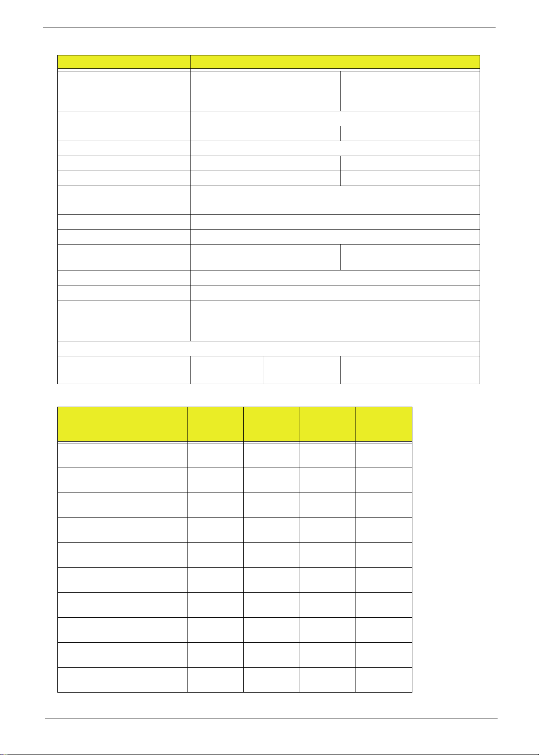
Memory Combinations
Slot 1 Slot 2 Total Memory
0MB 1024MB 1024MB
0MB 2048MB 2048MB
0MB 4096MB 4096MB
1024MB 0MB 1024MB
1024MB 512MB 1536MB
1024MB 1024MB 2048MB
1024MB 2048MB 3072MB
2048MB 0MB 2048MB
2048MB 512MB 2560MB
2048MB 1024MB 3072MB
2048MB 2048MB 4096MB
4096MB 4096MB 8192MB
Above table lists some system memory configurations. You may combine DIMMs with various capacities to
form other combinations. On above table, the configuration of slot 1 and slot 2 could be reversed.
USB Port
Item Specification
Chipset SB710 embedded
USB compliance level 2.0
OHCI 5 OHCI and 2 EHCI Host controllers
Number of USB port(s) 6
Location 2 left, 4 back
Wireless Module
Item Specification
Model and Type Lite-On WN6605LH-AA, Quanta EM307 WLAN EM307
Conformity 802.11 b/g/n WiMax
Modulation Techniqu e OFDM with BPSK QPSK, 16QAM, 64QAM (g/n), DQPSK,
DBPSK and CCK (b)
Frequency Range 2412 ~ 2484MHz ISM band
Channels 1---14 channels for active channels
Data Rate (Mbps) 802.11b data rate: 11,5.5,2,1 Mbps with DBPSK and DQPSK
modulation
802.11 g data rate: 54, 48, 36, 24, 18, 12, 9, 6Mbps
Security (WEP) WPA, WPA2
Operating
Temperature
Touchscreen
Item Specifications
Touchscreen Windows 7 multitouch and gestures
Operating -10°C to +75°C
Storage -40°C to +80°C
Chapter 1 15
Page 26

Hard Disk Drive Interface
Item Specifications
Vendor & Model Name
Capacity (GB)
Bytes per sector
Data heads
Drive Format
Disks
Spindle speed (RPM)
Performance Specifications
Buffer size
Interface
Internal transfer rate (MB/
sec, max)
I/O data transfer rate
(Mbytes/sec max)
DC Power Requirements
Voltage
Hitachi
HDT721016SLxxx
HCT721016SLxxx
HDT721025SLxxx
HCT721025SLxxx
HDT721032SLxxx
HCT721032SLxxx
160, 160, 250,
250, 320, 320
1, 1, 2, 2, 2, 2 3 6 6
1223
8MB 8MB 16 32
Hitachi
HDT721050SLxxx
HCT721050SLxxx
HDE721050SLxxx
500 640, 640, 640,
300MB/s maximum
1406 Mbits/s maximum
Hitachi
HDT721064SLxxx
HCT721064SLxxx
HDE721064SLxxx
HDT721075SLxxx
HCT721075SLxxx
HDE721075SLxxx
750, 750, 750,
512
7200
SATA
+5.0V ± 5%.
Hitachi
HDT721010SLxxx
HCT721010SLxxx
HDE721010SLxxx
1000
Hard Disk Drive Interface (continued)
Item Specifications
Vendor & Model Name
Capacity (GB)
Bytes per sector
Data heads
Seagate ST31000528AS,
ST3750528AS,
ST3500418AS,
ST3500410AS,
ST3320418AS
(Pharaoh)
1000, 750 250, 160 100, 80, 60, 50, 40, 30
512 512 512
4 1 4, 3, 3, 2, 2, 2
Drive Format
Disks
2, 2, 1, 1, 1 1 2, 2, 2, 1, 1, 1,
Spindle speed (RPM)
Performance Specifications
Buffer size
32MB, 32MB, 16MB,
16MB, 16MB
Interface
Internal transfer rate
(MB/sec, max)
I/O data transfer rate
(Mbytes/sec max)
DC Power Requirements
Voltage
Seagate ST3250318AS,
ST3160318AS
(Pharaoh)
7200 5400
8MB 8MB, 8MB, 8MB, 2MB,
SATA
300MB/s maximum
300
5V +10% / -7.5% -.12V +10% / -7.5%
Seagate ST9100822A,
ST9808210A, ST960821A,
ST950212A, ST9402113A,
ST930219A
(Momentus)
2MB, 2MB
16 Chapter 1
Page 27

Hard Disk Drive Interface (continued)
Item Specifications
Vendor & Model Name
Capacity (GB)
Western Digital,
WD3200AAJS,
WD2500AAJS,
WD1600AAJS,
WD800AAJS
320, 250, 160, 80 320, 250, 160 500, 640 500, 640
Bytes per sector
Data heads
2, 2, 1, 1 2, 2, 1 4 4
Drive Format
Disks
Spindle speed (RPM)
Performance Specifications
Buffer size
8MB 16MB 8MB 16MB
Interface
Internal transfer rate (MB/
sec)
I/O data transfer rate
(Mbytes/sec max)
DC Power Requirements
Voltage
Western Digital
WD3200AAKS,
WD2500AAKS,
WD1600AAKS
12
70MB/s sustained
3000 Mbits/s maximum
+5.0V ± 5%.and +12.0V ± 10%
Western Digital
WD5000AAJS,
WD6400AAJS
512
7200
SATA
Western Digital
WD5000AAKS,
WD6400AAKS
Video Interface
Item Specification
Chipset UMA: Ibex Peak H57
Discrete: GT240M 1024MB DDR3 (N10P-GS)
G210M 512MB DDR3(N10M-GS)
Package FCBGA951
Interface PCIE 2.0 x16
VRAM
Item Specification
Chipset Nvidia Geforce G210M
Memory size Onboard 512MB memory; 64-bits memory interface
Interface MXM 3.0
Audio Interface
Item Specification
Audio Controller Alc268 supporting Azalia function
Audio onboard or optional Onboard
Mono or Stereo Stereo
Internal Microphone Headphone /Mic /line out support
Internal Speaker 5W Speakers 300Hz to 20kHz +/- 3dB
Chapter 1 17
Page 28

Keyboard Controller
Item Specification
Controller IT8512E/NX-L embedded
Total number of keypads
Windows logo key
Hotkeys
Bluetooth
Item Specification
Chipset Broadcom BCM2046, Bluetooth2.1 + EDR, USB interface module
Data throughput
Protocol Bluetooth 2.1 + EDR
Connector type USB
TV Tuner
Item Specification
TV Tuner • ATSC/QAM/HRC/IRC/Standard Cable
• DVB-T
• ISDB-T
• DMB-T/H
• Meets Microsoft Media Center TV Tuner requirements
VGA Controller
Item Specifications
VGA
Controller
HDMI Port- Not available with this model
Chipset
Throughput
Compliance level
• INTEL GL40/GM45 Internal Graphics
• Direct 3D, Integrated LVDS
• Dual view and Dual video
•TV-out
• ATI M92-M
Item Specification
18 Chapter 1
Page 29
LCD 23”
Item Specification
Vendor/model name Samsung
L TM230HT01-A05
LG
LM230WF1
LTM230HT01
Screen Diagonal (mm) 58 4.2
Active Area (mm) 509.76 x 286.74
Display resolution (pixels) 1920 x 1080
Pixel Pitch 0.2655 x 0.2655 0.265 x 0.265
Display Mode Normally White
Typical White Luminance (cd/
2
) also called Brightness
m
300
Supported Colors 16.7M
Contrast Ratio 1000
Response Time (Optical Rise
5 1.3 / 3.7
Time/Fall Time) msec
Nominal Input Voltage VDD 5
Interface LVDS
Viewing Angle (degree)
80
Horizontal:
Vertical:
Temperature Range (°C)
Operating
Storage (shipping)
0 - 50
-25 - 60
0 - 35
5 - 35
0 - 50
-20 - 60
LCD Display Supported Resolution
Resolution
24 bits
(UMA)
30 bits
36 bits
(Discrete)
800x600 Y N Y N
1024x768 Y N Y N
11 52x864 Y N Y N
1280x600 Y N N N
1280x720 Y N Y N
1280x768 Y N Y N
1280x800 Y N Y N
1280x960 Y N Y N
1280x1024 Y N Y N
1360x768 Y N Y N
48 bits
Chapter 1 19
Page 30
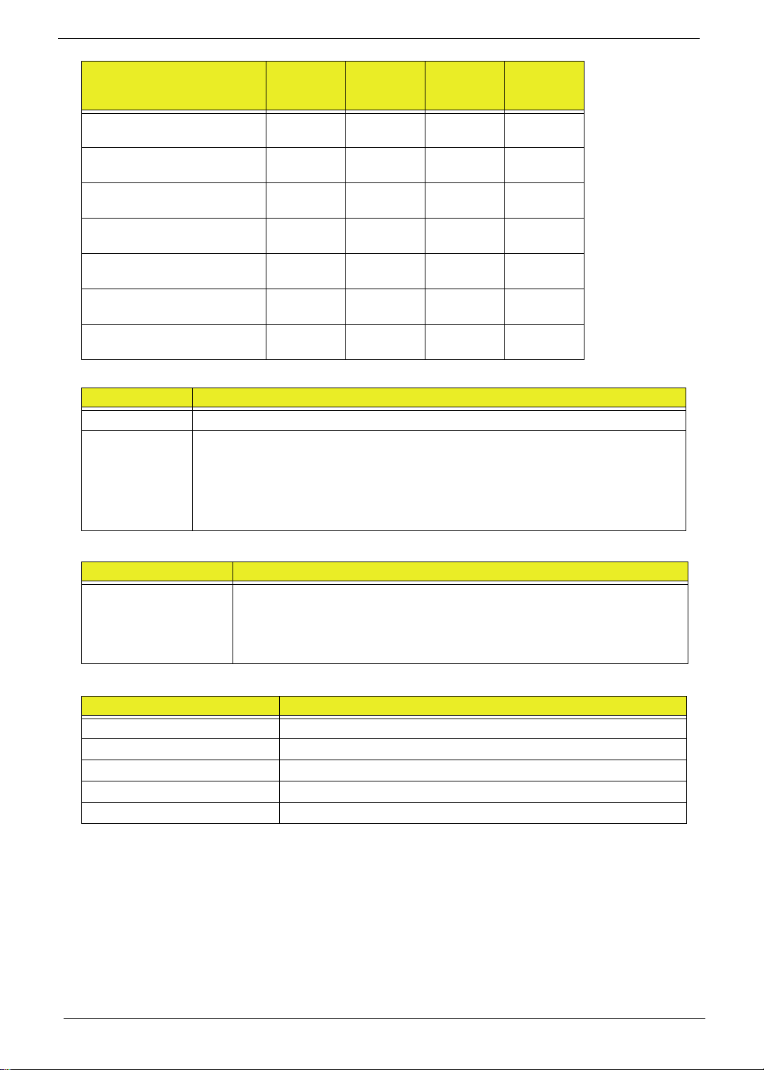
Resolution
1366x768 Y N N N
1400x900 Y N N N
1400x1050 Y N N N
1600x900 Y N Y N
1600x1024 N N Y N
1680x1050 Y N Y N
1920x1080 Y N Y N
Power Supply
Item Specifications
AC Input • Auto ranging from 100V to 240V and 50Hz to 60Hz
DC Output • 5V, 40W; 3.3V, 19.8W; 12V, 174W; 12V, 6W, 5VSB, 10W
• Uses 3 prong ICE-320-C13 or IEC-320-C5 connector for AC power
• Hold up time of 16ms under maximum load
• Meet <1W Standby Energy S tar requirement for Desktop Category B
• Meet EU Lot 6 requirement
24 bits
(UMA)
30 bits
36 bits
(Discrete)
48 bits
RTC Battery
Item Specifications
Lithium Rechargeable
Battery
AC Adaptor
Item Specification
Input rating AC 100V - 240V, 50/60Hz
Output 19V 135W
Maximum input AC current
Inrush current
Efficiency
• Model: MIT CR2032
• Voltage:2.5-3.0V
• Capacity: 210mAh
• Vendor: Mitsubishi
20 Chapter 1
Page 31

System Power Management
Item Specification
Mech. Off (G3) Al devices in the system are turned off completely.
Working (G0/S0) Individual devices such as the CPU and hard disc may be power
managed in this state.
Suspend to RAM (S3) CPU set power down
VGA Suspend
PCMCIA Suspend
Audio Power Down
Hard Disk Power Down
CD-ROM Power Down
Super I/O Low Power mode
Save to Disk (S4) Also called Hibernation Mode. System saves all system states and
data onto the disc prior to power off the whole system.
Chapter 1 21
Page 32

22 Chapter 1
Page 33

Chapter 2
System Utilities
BIOS Setup Utility
The BIOS Setup Utility is a hardware configuration program built into your computer’s BIOS (Basic Input/
Output System).
Y our computer is already properly configured and optimized, and you do not need to run this utility . However , if
you encounter configuration problems, you may need to run Setup. Please also refer to Chapter 4
Troubleshooting when problem arises.
To activate the BIOS Utility, press F2 during POST (when “Press <F2> to enter Setup” message is prompted
on the bottom of screen).
Press <F12> during POST to enter multi-boot menu. In this menu, user can change boot device without
entering BIOS SETUP Utility.
Navigating the BIOS Utility
There are six menu options: Information, Main, Advanced, Security, Boot, and Exit.
Follow these instructions:
• To choose a menu, use the left and right arrow keys.
• To choose an item, use the up and down arrow keys.
• To change the value of a parameter, press F5 or F6.
• A plus sign (+) indicates the item has sub-items. Press Enter to expand this item.
• Press Esc while you are in any of the menu options to go to the Exit menu.
• In any menu, you can load default settings by pressing F9. You can also press F10 to save any
changes made and exit the BIOS Setup Utility.
NOTE: You can change the value of a parameter if it is enclosed in square brackets. Navigation keys for a
particular menu are shown on the bottom of the screen. Help for parameters are found in the Item
Specific Help part of the screen. Read this carefully when making changes to parameter values. Please
note that system information is subject to different models.
Chapter 2 23
Page 34

CMOS Setup Utility
The CMOS Setup Utility screen displays a list of the functions and features available in the BIOS.
CMOS Setup Utility - Copyright (C) 1985-2010, American Megatrends Inc.
Product Information
Standard CMOS Features
Advanced Bios Features
Advanced Chipset Features
Integrated Peripherals
Power Management Features
:Move
F1: General Help
Use the arrow keys to scroll to the required menu and press Enter.
Enter:Select
-/+/ : Value
F9 : Optimized Defaults
PC Health Status
Frequency Voltage Control
BIOS Security Features
Load Default Settings
Save and Exit Setup
Exit Without Saving
F10 : Save ESC : Exit
24 Chapter 2
Page 35

Product Information
CMOS Setup Utility - Copyright (C) 1985-2010, American Megatrends Inc.
Product Information
-/+/ : Value
Product Information Overview
Help Item
Processor Type
Intel (R) Core(TM) i7 CPU 860 @ 2.80GHz
Processor Speed 2.80GHz
System Memory 4096MB
Product Name ZX6910
System Serial Number PWGJNJNJNJ00500F4D6900
System BIOS Version P01-A3
BIOS Release Date 04/21/2010
Asset Tag Number
EC Firmware Version R1.03
:Move
F1: General Help
Enter:Select
F10 : Save ESC : Exit
F9 : Optimized Defaults
The Product Information screen displays a summary of the computer hardware information.
NOTE: The system information is subject to different models.
Parameter Description
Processor Type This field shows the system processor type.
Processor Speed This field shows the speed of the processor.
System Memory This field reports the memory size of the system.
Product Name Th is field shows product name of the syste m.
System Serial Number This field displays the serial number of this unit.
System BIOS Version Displays system BIOS version.
BIOS Release Date This field displays the release date of the system BIOS.
Asset Tag Number This field displays the asset tag number.
EC Firmware Version This field displays the EC Firmware version number.
Chapter 2 25
Page 36

Standard CMOS Features
CMOS Setup Utility - Copyright (C) 1985-2010, American Megatrends Inc.
Standard CMOS Features
Help Item
System Date [Tue 04/25/2010]
System Time [05:00:33]
AHCI Port1 [Hard Disk]
AHCI Port2 [ATAPI CDROM]
AHCI Port4 [Not Detected]
Halt On [All, But Keyboard]
Use [Enter], [TAB]
or [Shift-TAB] to
select a field.
Use [+] or [-] to
configure system Date
-/+/ : Value
:Move
F1: General Help
Enter:Select
F10 : Save ESC : Exit
F9 : Optimized Defaults
The Standard CMOS Features screen allows the user to set the system time and date as well as set HDD and
ODD options.
NOTE: The screen above is for your reference only. Actual values may differ.
The table below describes the parameters in this screen. Settings in boldface are the default parameter
settings.
Parameter Description Format/Option
System Date Sets the system date. Format MM/DD/YYYY (month/
System Time Sets the system time. The hours are displayed
with 24-hour format.
SATA Port 1
SATA Port 2
AHCI Port 4
Halt On Instructs the BIOS to halt during boot up for
the selected error parameter.
day/year)
Format: HH:MM:SS
(hour:minute:second)
Options:
• All Errors
• No Errors
• All, But keyboard
26 Chapter 2
Page 37

Advanced BIOS Features
CMOS Setup Utility - Copyright (C) 1985-2010, American Megatrends Inc.
Advanced BIOS Features
Help Item
Quick Boot [Enabled]
Quiet Boot [Enabled]
1st Boot Device [HDD PO-WDC WD20FAD]
2nd Boot Device [CD/DVD:P1-Slimtype]
3rd Boot Device [Removable Device]
4th Boot Device [LAN]
Hard Disk Drive Priority [Press Enter]
Optical Disk Drive Priority [Press Enter]
Bootup Num-Lock [On]
USB Beep Message [Disabled]
Allows BIOS to skip
certain steps during
booting. This will
reduce the time
needed to boot the
system.
-/+/ : Value
:Move
F1: General Help
Enter:Select
F10 : Save ESC : Exit
F9 : Optimized Defaults
The Advanced BIOS Features screen allows configuration of the various advanced BIOS options.
The table below describes the items, menus, and submenus in this screen.
Parameter Description Format/Option
Quick Boot Allows BIOS to skip certain steps while
booting.
Quiet Boot Allows BIOS to change display parameters
while booting changing boot speed.
1st Boot Device
2nd Boot Device
3rd Boot Device
4th Boot Device
Hard Disk Drive Priority Enter to set the boot drive priority. Press Enter to set the order
Optical Disk Driver Priority Enter to set the boot driver priority. Press Enter to set the order
Boot Num-Lock Turns Num-Lock on or off on boot up. On or Off
USB Beep Message Allows a beep during USB enumeration. Enabled or Disabled
Enabled or Disabled
Enabled or Disabled
priority
priority
Chapter 2 27
Page 38

Advanced Chipset Features
CMOS Setup Utility - Copyright (C) 1985-2010, American Megatrends Inc.
Advanced Chipset Features
Help Item
Intel EIST [Enabled]
Intel(R) RurboMode tech [Enabled]
Intel XD Bit [Enabled]
Intel VT [Enabled]
Memory Hole Remapping [Enabled]
Disable: Disable GV3
Enable: Enable GV3
-/+/ : Value
:Move
F1: General Help
Enter:Select
F10 : Save ESC : Exit
F9 : Optimized Defaults
The Advanced Chipset Features screens.
The table below describes the items, menus, and submenus in this screen.
Parameter Description Format/Option
Intel XD Bit When disabled this forces the XD feature
flag to always return to 0.
Memory Hole Remappingt When enabled allows remapping of
overlapped PCI memory above the total
physical memory.
Video Memory Size Sets the amount of system memory used by
the internal graphics device.
DVMT mode Turns on DVMT mode for use with internal
DVMT/Fixed Memory Size Set the memory allocated for DVMT. (XP
graphics.
only)
Enabled or Disabled
Enabled or Disabled
Enter to set
Select DVMT
Options:
•128MB
•256MB
• Maximum
28 Chapter 2
Page 39

Integrated Peripherals
CMOS Setup Utility - Copyright (C) 1985-2010, American Megatrends Inc.
Integrated Peripherals
Help Item
Onboard SATA Controller [Enabled]
Onboard SATA Mode [AHCI]
Onboard USB Controller [Enabled]
USB Storage Emulation [Auto]
Onboard Audio Controller [Enabled]
Onboard LAN Controller [Enabled]
Onboard LAN Option ROM [Disenabled]
Onboard CIR Controller [Enabled]
-/+/ : Value
:Move
F1: General Help
Enter:Select
F10 : Save ESC : Exit
F9 : Optimized Defaults
Options
Disabled
Enabled
The Integrated Peripherals screen contains parameters for device peripherals.
The table below describes the items, menus, and submenus in this screen.
Parameter Description Format/Option
Onboard SATA Controller Enable the SATA controller Enabled or Disabled
Onboard SATA Mode Set the SATA mode Options:
Onboard USB Controller Enable the USB controller. Enabled or Disabled
USB Storage Emulation Set the USB storage emulation Options:
Onboard Audio Controller Enable or disable the audio controller Enabled or Disabl ed
Onboard LAN Controller Enable or disable the LAN controller Enabled or Disabled
Onboard LAN Option ROM Disable or enable LAN optional ROM Disabled or Enabled
Onboard CIR Controller Enable or disable the CIR Controller Enabled or Disable
•IDE
• AHCI
•Auto
• Floppy
•Hard Disk
Chapter 2 29
Page 40

Power Management Features
CMOS Setup Utility - Copyright (C) 1985-2010, American Megatrends Inc.
Power Management Features
Help Item
ACPI Suspend Mode [S3 (STR)]
Power On by RTC Alarm [Disabled]
Power On by Onboard LAN [Disabled]
Wake Up by USB KB/Mouse [Enabled] Mode
Restore on AC Power Loss [Last State]
-/+/ : Value
:Move
F1: General Help
Enter:Select
F10 : Save ESC : Exit
F9 : Optimized Defaults
Select the ACPI
state used for
System Suspend.
The Power Management Features screen contains parameters used for device power management.
The table below describes the parameters in this screen. Settings in boldface are the default and suggested
parameter settings.
Parameter Description Option
ACPI Suspend Mode Choose between STR (Suspend to Ram) and POS
(Power on Standby). POS uses more power during
suspend.
Power On by RTC Alarm Disable or Enable auto wake up at a fixed time
everyday.
Power On by onboard
LAN
Wake Up by USB KB/
Mouse
Restore On AC Power
Loss
Disable or Enable wake up when the system power is
off and a LAN device is activated.
Disable or Enable wake up when the system is in
standby and a USB device is activated.
Set the state the device returns to in the even t of AC
power loss. Off causes the device to remain off in the
event of power loss, On restarts the device when AC
power resumes, and Last State returns the device to
the state it was at when power loss occurred.
S1(POS)/
S3(STR)
Disabled or
Enabled
Disabled or
Enabled
Enabled or
Disabled
Off or On or Last
State
30 Chapter 2
Page 41

PC Health
The PC Health screen displays CPU/Chipset temperature information and contains customizable safety
monitors for the CPU.
CMOS Setup Utility - Copyright (C) 1985-2010, American Megatrends Inc.
PC Health
CPU Temperature (PECI Mode) : 48°C
CPU Fan1 Speed : 2095 RPM
CPU Fan2 Speed : 2103 RPM
+1.1V : 1.15 V
+3.30V : 1.09 V
+5.00V : 5.05 V
+12.0V : 12.12 V
+1.5V : 1.45 V
Smart Fan [Enabled]
:Move
The table below describes the parameters in this screen. Settings in boldface are the default and suggested
parameter settings.
Parameter Description Option
CPU Temperature Displays the current CPU temperature (°C). This field
CPU Fan1 Speed Displays the current CPU fan speed. This field is read
CPU Fan2 Speed Displays the current system fan speed. This field is
+5.00V Displays the power supply voltage for the nominal 5V
+3.30V Displays the power supply voltage for the nominal
+1.1V Displays the nominal 1.1 V bus. This field is read only. N/A
+12.0V Displays the power supply voltage for the nominal
Smart Fan En able d all ows auto fan c ont rol. If disabled the fan
Enter:Select
F1: General Help
is read only.
only.
read only.
bus. This field is read only.
3.3V bus. This field is read only.
12.0V bus. This field is read only.
runs continuously at maximum speed.
-/+/ : Value
F9 : Optimized Defaults
F10 : Save ESC : Exit
Help Item
If disabled, System Fan
will run direstly the
maximum speed.
N/A
N/A
N/A
N/A
N/A
N/A
Enabled or
Disabled.
Chapter 2 31
Page 42

Frequency Voltage Control
CMOS Setup Utility - Copyright (C) 1985-2010, American Megatrends Inc.
Frequency Voltage Control
Help Item
Enable Clock to All PCEI [Enabled]
Spread Spectrum [Enabled]
Options
Disabled
Enabled
-/+/ : Value
:Move
F1: General Help
Enter:Select
F10 : Save ESC : Exit
F9 : Optimized Defaults
The Frequency Voltage Control Screen to set memory and processor parameters.
The table below describes the parameters in this screen. Settings in boldface are the default and suggested
parameter settings.
Parameter Description Option
Enable Clock to All PCIE Enabled or disabled for reducing clock consumption. Enabled or
Spread Spectrum Enabled to assist with EMI emissions, Disabled to
assist with stability.
Disabled
Enabled or
Disabled
32 Chapter 2
Page 43

BIOS Security Features
CMOS Setup Utility - Copyright (C) 1985-2010, American Megatrends Inc.
BIOS Security Features
Help Item
Supervisor Password :Not Installed
User Password :Not Installed
Change Supervisor Password [Press Enter]
Install or change the
password.
-/+/ : Value
:Move
F1: General Help
Enter:Select
F10 : Save ESC : Exit
F9 : Optimized Defaults
The BIOS Security Features screen contains parameters that help safeguard and protect your computer from
unauthorized use.
The table below describes the parameters in this screen.
Parameter Description Option
Supervisor Password Shows the setting of the Supervisor password Not Instal le d or
User Password Shows the setting of the user password Not Installed or
Change Supervisor
Password
Change User Password Press Enter to set the user password. When set, this
Security Option Press Enter to set the security option. This option is
NOTE: When prompted to enter a password, only three tries are allowed before the system halts. Do not lose
the password.
Press Enter to set the supervisor password. When
set, this password protects the BIOS Setup Utility
from unauthorized access. The user can not either
enter the Setup menu nor change the value of
parameters.
password prompts the user to enter a password
during the boot sequence. The user must enter the
correct password to be able to continue booting the
system. This option is only available if a supervisor
password has been specified
only available if a supervisor password has been
specified.
Installed
Installed
N/A
N/A
Chapter 2 33
Page 44

Setting a Password
Set Supervisor Password
Enter New Password [ ][ ]
Confirm New Password [ ]
Set Supervisor Password
Enter Current Password [ ][ ]
Enter New Password [ ]
Confirm New Password [ ][ ]
Follow these steps as you set the user or the supervisor password:
1. Use the and keys to highlight the Set Supervisor Password parameter and press the Enter key. The
Set Supervisor Password box appears:
2. Type a password in the “Enter New Password” field. The password length can not exceeds 8
alphanumeric characters (A-Z, a-z, 0-9, not case sensitive). Retype the password in the “Confirm New
Password” field.
IMPORTANT:Be very careful when typing your password because the characters do not appear on the screen.
3. Press Enter. After setting the password, the computer sets the User Password parameter to “Set”.
4. If desired, you can opt to enable the Password on boot parameter.
5. When you are done, press F10 to save the changes and exit the BIOS Setup Utility.
Removing a Password
Follow these steps:
1. Use the and keys to highlight the Set Supervisor Password parameter and press the Enter key. The
Set Password box appears:
2. Type the current password in the Enter Current Password field and press Enter.
3. Press Enter twice without typing anything in the Enter New Password and Confirm New Password fields.
The computer then sets the Supervisor Password parameter to “Clear”.
4. When you have changed the settings, press u to save the changes and exit the BIOS Setup Utility.
34 Chapter 2
Page 45

Changing a Password
Set Supervisor Password
Enter Current Password [ ][ ]
Enter New Password [ ]
Confirm New Password [ ][ ]
Setup Notice
Changes have been saved.
[Continue][Continue]
Setup Warning
Invalid Password.
[Continue][Continue]
Setup Warning
Passwords do not match.
Re-enter password.
[Continue][Continue]
1. Use the and keys to highlight the Set Supervisor Password parameter and press the Enter key. The
Set Password box appears.
2. Type the current password in the Enter Current Password field and press Enter.
3. Type a password in the Enter New Password field. Retype the password in the Confirm New Password
field.
4. Press Enter. After setting the password, the computer sets the User Password parameter to “Set”.
5. If desired, you can enable the Password on boot parameter.
6. When you are done, press F10 to save the changes and exit the BIOS Setup Utility.
If the verification is OK, the screen will display as following.
The password setting is complete after the user presses Enter.
If the current password entered does not match the actual current password, the screen will show you the
Setup Warning.
If the new password and confirm new password strings do not match, the screen will display the following
message.
Chapter 2 35
Page 46

BIOS Flash Utilities
The BIOS flash memory update is required for the following conditions:
• New versions of system programs
• New features or options
• Restore BIOS when it becomes corrupted.
This section contains instructions for the following BIOS utilities:
• DOS flashit utility
• WinPhlash utility
•DMI Tools
36 Chapter 2
Page 47

DOS Flash Utility
Perform the following steps to use the DOS Flash Utility:
1. Copy the flash utilities to the bootable device.
2. Attach the device to the system and restart.
3. Press F2 during boot to enter the Setup Menu.
4. Select Boot Menu to modify the boot priority order, for example, if using USB HDD to Update BIOS, move
USB HDD to position 1.
IMPORTANT:Please use a device that can be booted in DOS mode (FAT 16 or FAT 32 partitions only)
CMOS Setup Utility - Copyright (C) 1985-2010, American Megatrends Inc.
Quick Boot [Enabled]
Quiet Boot [Enabled]
1st Boot Device [HDD PO-WDC WD20FAD]
2nd Boot Device [CD/DVD:P1-Slimtype]
3rd Boot Device [Removable Device]
4th Boot Device [LAN]
Hard Disk Drive Priority [Press Enter]
Optical Disk Drive Priority [Press Enter]
Bootup Num-Lock [On]
USB Beep Message [Disabled]
:Move
F1: General Help
Advanced BIOS Features
Enter:Select
-/+/ : Value
F9 : Optimized Defaults
Help Item
Allows BIOS to skip
certain steps during
booting. This will
reduce the time
needed to boot the
system.
F10 : Save ESC : Exit
5. Navigate to the BIOS file in DOS mode.
6. Enter the command “FBB” to begin the flash BIOS process. The flash process will run automatically.
When complete, the system will restart automatically.
7. When the system boots, then it will display "Press Del to Enter BIOS Setup" and "Press F1 to Continue".
8. Press F1 to load the CMOS defaults or press Del to go BIOS SETUP and manually configure BIOS.
Chapter 2 37
Page 48

Win Flash Utility
Perform the following steps to use the WinFlash Utility:
1. Open the Start menu and type CMD to open command mode.
2. Type “fbbwin64” to flash BIOS. The process will start automatically.
IMPORTANT:During the flash process the keyboard and mouse will not function.
3. Once the flash process has finished, shutdown the system and press the power button to restart.
4. When the system boots, then it will display "Press Del to Enter BIOS Setup" and "Press F1 to Continue".
5. Press F1 to load the CMOS defaults or press Del to go BIOS SETUP and manually configure BIOS.
38 Chapter 2
Page 49

Using DMI Tools
Use QDMI30A to change the asset tag, product name, or serial number of the machine.
1. Copy the file qdmi30a.exe to USB flash disk with bootable diskette or USB drive.
2. Press F2 during boot to enter the Setup Menu.
3. Select Boot Menu to modify the boot priority order, for example, if using a USB HDD to run DMI Tools,
move USB HDD to position 1.
4. Boot into DOS.
5. Key in “qdmi30a” then click “Enter”. The following screen appears.
Select one of the functions to modify. To modify the asset tag, key in “1” and then key in a string for the new
asset tag as shown below.
To modify the product number, key in “2” then key in a new string for the product number as shown below.
To modify the serial number, key in “3” then key in a new string for the serial number as shown below.
To modify the 1394 GUID number, key in “4” then key in a new string for the 1394 GUID number as shown
below
Chapter 2 39
Page 50

Chapter 3
Machine Disassembly and Replacement
WARNING:This computer has two highly sensitive touchscreen sensors on the top left and right
corners of the LCD. The sensors are an integral part of the LCD and cannot be separately
replaced. The sensors are exposed as soon as the rear cover is removed.
During disassembly:
• DO NOT make contact with the sensors.
• Raise the LCD off any surface it is placed face down on so that the sensors do not rest on
the surface.
• ALWAYS employ an antistatic mat.
IMPORTANT:The outside housing and color ma y vary from the images that appear in this section.
This chapter contains step-by-step procedures on how to disassemble the computer for maintenance and
troubleshooting.
Disassembly Requirements
To disassemble the computer, you need the following tools:
• Wrist grounding strap and conductive mat for preventing electrostatic discharge
• Flat screwdriver
• Three (3) sizes of Philips screwdrivers: 7mm, 4mm and 2mm
• Pin or unbent paperclip or similar.
• Block of sponge or similar soft material smaller in surface area than the LCD and at least 1”
(2.5cm) high.
NOTE: The screws for the different components vary in size. During the disassembly process, group the
screws with the corresponding components to avoid mismatch when putting back the components.
General Information
Pre-disassembly Instructions
Before proceeding with the disassembly procedure, make sure that you do the following:
1. Turn off the power to the system and all peripherals.
2. Unplug the AC adapter and all power and signal cables from the system.
3. Place the system on an antistatic mat.
The flowchart provided in the succeeding disassembly section illustrates the entire disassembly sequence.
Observe the order of the sequence to avoid damage to any of the hardware components.
Main Screw List
Screw Quantity Part Number
M2.5*4.0-I(NYLOK)IRON 6 86.G8507.001
M2.5*4.0-I(NI)(NYLOK)IRON 26 86.G8507.002
M2.5*7.0-I(B) (NYLOK)IRON 4 86.G8507.003
M4.0*6-I(NI,NYLOK) 4 86.G8507.004
Chapter 3 40
Page 51

Screw Quantity Part Number
M2.5*5.0-I(BNI)(NYLOK)IRON 3 86.G8507.005
M3*4-I(NI)(NYLOK)IRON 4 86.G8507.006
6-32UNC*5-B(NYLOK)IRON 4 86.G8507.007
M2.0*2.5-I (BNI,NYLOK)IRON 4 86.G8507.008
M2.0*3.0-I-NI-NYLOK IRON 7 86.G8507.009
41 Chapter 3
Page 52

Disassembly Process
Remove
Inverter Board
Remove
HDD Module
Turn off power and
disconnect all
cables before
proceeding
Remove
Stand Assembly
Remove
Rear Cover
Remove
ODD Bezel
Remove
TV Module
Remove
Speakers
Remove
Bluetooth Module
Remove
WLAN Board
Remove
FAN
Remove
Mainboard Shield
Remove
Mainboard
Remove
VGA Board
Remove
Audio Board
Remove
USB Board
Remove
LCD Panel
Remove
IR Receiver
Remove
Home Button
Board
Remove
ODD Module
Remove
DIMM Module
Remove
Thermal Module
Remove
CPU
Remove
Frame
Remove
Power Board
Remove
Antennas
Remove
Webcam
Remove
Touchscreen
Board
Disassembly Flowchart
Chapter 3 42
Page 53

Screw List
Step Screw Quantity
Stand Cover M2.5*4 2
Stand Hinge M4*6 Ni 4
Rear Cover M2.5*7 4
Audio Board M2.5*4 Ni 2
HDD M2.5*4 Ni 2
HDD Bracket M3*4 Ni 4
ODD M2.5*4 Ni 2
ODD Brackets M2*2.5 Ni 4
Inverter Board M2.5*4 Ni 2
Touchscreen Control Board M2.5*4 Ni 2
Mainboard Shielding M2.5*4 Ni 7
WLAN M2*3 1
TV Tuner Module M2.5*4 Ni 1
VGA Card M2.5*4 Ni 4
Fan M2.5*5 Ni 3
Mainboard M2.5*4 Ni 1
USB Board M2.5*4 Ni 2
IR Receiver M2*3 1
Frame M2.5*4 Ni 15
LCD Panel M3*4 4
Power Board M2.5*4 Ni 2
Camera M2*3 2
Antennas M1.7*4 2
Speakers M2.5*4.0-I(NYLOK)IRON 6
43 Chapter 3
Page 54

Removing the RAM Covers
1. See “Pre-disassembly Instructions” on page 40.
2. Apply pressure to one end of the RAM Cover, while pulling up with the opposite hand as shown.
3. Lift the RAM Cover clear of the device.
4. Grasp the Hinge Cover with both hands.
Chapter 3 44
Page 55

5. Lift the Hinge Cover clear of the device.
45 Chapter 3
Page 56

Removing the RAM
1. See “Removing the RAM Covers” on page 44
2. Lift the RAM Shielding clear of the device.
3. Unlock the latches on either side of the RAM by pressing down as shown. There is an audible click when the
latch is unlocked.
4. Lift each RAM module from its slot.
Chapter 3 46
Page 57

Removing the Rear Covers
1. See “Removing the RAM” on page 46
2. Remove the six (6) screws that secure the Rear Covers.
Step Size Quantity Screw Type
Rear Covers M2.5*6.0 6
3. Use both hands to gently push the rear cover outward from the device as shown.
4. Repeat the previous step for the remaining rear cover.
47 Chapter 3
Page 58

Removing the Back Cover
1. See “Removing the Touchscreen Control Board” on page 59
2. Remove the fourteen (14) screws securing the Back Cover.
Step Size Quantity Screw Type
Back Cover 2.5*8
2.4*8
3. Use both hands to move the Hinge up into the stand position. There is an audible click when the Hinge is
locked in position.
NOTE: In order to lift the Back Cover away, the Hinge must be in the stand position.
Chapter 3 48
Page 59

4. Place one hand firmly on the Back Cover. Use the opposite hand to pry the Bezel away, working from one
corner to the other as shown. Repeat this step until all guides along the bottom of the device are unlocked.
5. Place one hand firmly on the Hinge. Use the opposite hand to pull the top of the Back Cover away from the
Bezel, working from one corner to the other as shown. Repeat this step until all guides along the top of the
device are unlocked.
6. Lift the Back Cover clear of the device.
49 Chapter 3
Page 60

Removing the Hinge
1. See “Removing the Back Cover” on page 48
2. Replace the Hinge to the carry position.
3. Remove the six (6) screws securing the Hinge.
Step Size Quantity Screw Type
Hinge M4*8 6
4. Lift the Hinge clear of the device.
Chapter 3 50
Page 61

Removing the Mainboard Shielding
1. See “Removing the Audio Board” on page 63.
2. See “Removing the Touchscreen Control Board” on page 59.
3. Remove the one (1) screw from the ground wire.
Step Size Quantity Screw Type
HDD Ground
Cable
M2.5*4 1
4. Remove the small power cable from the mainboard.
51 Chapter 3
Page 62

5. Detach the power cable from the mainboard.
6. Remove the adhesive tape holding the HDD ground cable to the HDD.
7. Remove the one (1) screw from the ground wire.
Step Size Quantity Screw Type
Converter
Ground Cable
M2.5*4 1
Chapter 3 52
Page 63

8. Disconnect the HDD cable.
9. Remove the power cable from the HDD.
10. Remove the six (6) screws.
Step Size Quantity Screw Type
Mainboard
Shielding
M2.5*4Ni 6
53 Chapter 3
Page 64

11. Lift the mainboard shielding away from the chassis.
Chapter 3 54
Page 65

Removing the Hard Disk Drive
1. See “Removing the Back Cover” on page 48.
2. Disconnect the HDD cable.
3. Remove the two (2) screws.
Step Size Quantity Screw Type
HDD M2.5*4 2
55 Chapter 3
Page 66

4. Slide the HDD towards the speakers to release it from the flanges.
5. Lift the HDD out of the chassis.
6. Remove the four (4) screws from the HDD bracket (both sides).
Step Size Quantity Screw Type
HD Bracket M3*4 4
Chapter 3 56
Page 67

7. Remove the brackets from the HDD.
57 Chapter 3
Page 68

Removing the Power Supply
1. See “Removing the Hinge” on page 50
2. Remove two (2) screws securing the Power Supply as shown.
Step Size Quantity Screw Ty pe
Power Supply M2.5*4 2
3. Lift the Power Supply clear of the device.
Chapter 3 58
Page 69

Removing the Touchscreen Control Board
1. See “Removing the Back Cover” on page 48
2. Remove the one (1) ground cable screw.
Step Size Quantity Screw Ty pe
Touchscreen
Control Board
M2.5*4 1
3. Disconnect the right (top in this image) touch sensor cable.
59 Chapter 3
Page 70

4. Disconnect the left (bottom in this image) touch sensor cable.
5. Disconnect the touchscreen board to mainboard cable.
6. Remove the two (2) screws.
Step Size Quantity Screw Type
Touchscreen Board M2.0*4 2
Chapter 3 60
Page 71

7. Lift the touchscreen board away.
61 Chapter 3
Page 72

Removing the Card Reader Board
1. Disconnect the Card reader cable.
2. Remove the two (2) screws.
Step Size Quantity Screw Type
Card Reader Board 2.5*4 2
3. Lift the card reader board away.
Chapter 3 62
Page 73

Removing the Audio Board
1. See “Removing the Back Cover” on page 48.
2. Disconnect the Audio board cable.
3. Remove the two (2) screws from the audio board.
Step Size Quantity Screw Type
Audio Board M2.5*4 2
63 Chapter 3
Page 74

4. Lift the audio board and cable away at an angle from the rear cover.
Chapter 3 64
Page 75

Removing the ODD Eject Board
1. See “Removing the Back Cover” on page 48
2. Disconnect the ODD Eject Board Cable.
3. Remove the one (1) screw from the ODD eject board.
Step Size Quantity Screw Type
Audio Board M2.5*4 2
65 Chapter 3
Page 76

4. Remove the ODD Eject Board.
Chapter 3 66
Page 77

Removing the ODD
1. See “Removing the Back Cover” on page 48.
2. Remove the two (2) screws.
Step Size Quantity Screw Type
ODD M2.5*4 2
3. Slide the ODD assembly out.
67 Chapter 3
Page 78

4. Lift the ODD away from the chassis.
5. Remove the two (2) screws from the side bracket and remove the bracket.
Step Size Quantity Screw Type
ODD Side Bracket M2*2.5 2
Chapter 3 68
Page 79

6. Remove the two (2) screws from the ODD rear bracket and remove the bracket.
Step Size Quantity Screw Type
ODD Rear Bracket M2*2.5 2
69 Chapter 3
Page 80

Removing the Inverter Board
1. See “Removing the Back Cover” on page 48.
2. Remove the adhesive covering the Inverter Board cable 1.
3. Disconnect the LCD to Inverter Board cable 1.
4. Unlock the cable clasp.
Chapter 3 70
Page 81

5. Disconnect the LCD to Inverter Board cable 2.
6. Disconnect the mainboard to inverter cable.
7. Remove the two (2) screws from the inverter board.
Step Size Quantity Screw Type
Inverter Board M2.5*3 2
71 Chapter 3
Page 82

8. Remove the Inverter Board.
Chapter 3 72
Page 83

Removing the Home Button Board
1. See “Removing the Back Cover” on page 48
2. Disconnect the Home Button board cable.
3. Remove the one (1) screw from the Home Button Board
Step Size Quantity Screw Type
Home Button
Board
73 Chapter 3
M2.5*4 1
Page 84

4. Remove the Home Button Board from the chassis.
Chapter 3 74
Page 85

Removing the Camera Module
1. See “Removing the Back Cover” on page 48
2. Remove the two (2) screws from the Camera Module
Step Size Quantity Screw Type
Camera Module M2.0*3 2
3. Lift the Camera Module out of the chassis.
75 Chapter 3
Page 86

4. Turn the Camera Module over.
5. Disconnect the cable from the Camera Module.
Chapter 3 76
Page 87

Removing the TV Tuner Module
1. See “Removing the Card Reader Board” on page 62.
2. Disconnect the TV Tuner antenna.
3. Remove the one (1) screw.
Step Size Quantity Screw Type
TV Card M2.0*3 1
77 Chapter 3
Page 88

4. Lift the TV module away.
Chapter 3 78
Page 89

Removing the Wireless LAN Module
1. See “Removing the Card Reader Board” on page 62.
2. Disconnect the WLAN antennas.
3. Remove the one (1) screw from the WLAN module.
Step Size Quantity Screw Type
WLAN M2.0*3 1
79 Chapter 3
Page 90

4. Lift the WLAN module away.
Chapter 3 80
Page 91

Removing the Thermal Module
1
2
4
3
1. See “Removing the Thermal Module” on page 81.
2. Disconnect the two (2) fan cables.
3. Loosen the four (4) captive screws in numerical order (1, 2, 3, then 4).
s
4. Lift the thermal module away.
81 Chapter 3
Page 92

Removing the Fans
1. See “Removing the Thermal Module” on page 81.
2. Remove the two (2) screws.
Step Size Quantity Screw Type
Fan 2.5*5 2
3. Remove the LVDS cable from the cable clips.
Chapter 3 82
Page 93

4. Remove the fan.
5. Remove the two (2) screws.
Step Size Quantity Screw Type
Fan 2.5*5 2
6. Remove the fan.
83 Chapter 3
Page 94

Removing the CPU
1. See “Removing the CPU” on page 84.
2. Unlock the CPU by pressing down on the locking latch and moving it out and away from the CPU.
3. Lift the CPU out of the package.
CAUTION: Avoid any contact with a thermal pad or thermal grease.
Chapter 3 84
Page 95

Removing the Mainboard
1
4
3
2
5
13
16
14
11
12
10
9
6
7
8
15
1. See “Removing the Card Reader Board” on page 62.
2. See “Removing the Thermal Module” on page 81.
3. See “Removing the CPU” on page 84.
4. Disconnect the sixteen (16) cables from the Mainboard as shown.
Item Description
1 LVDS Cable
2 CCD Cable
3 Inverter Cable
4MIC Cable
5 ODD Button Cable
6 Card Reader Cable
7 Bluetooth Cable
8 Home Button Cable
9 IR Cable
10 Touch Screen
11 Audio Cable
12 TV Tuner Cable
13 Light Foot Cable
14 USB Cable
15 Speaker Cable
16 Light Pipe Cable
85 Chapter 3
Page 96

5. Remove the adhesive tabs holding the Audio board cable to the mainboard.
6. Remove the two (2) screws.
Step Size Quantity Screw Ty pe
Mainboard M2.5*4 1
Chapter 3 86
Page 97

7. Lift the mainboard away.
NOTE: Circuit boards >10 cm² have been highlighted with a yellow rectangle as shown in the
previous image. Please detach the Circuit board and follow local regulations for disposal.
8. Disconnect the IR Board cable and remove.
87 Chapter 3
Page 98

9. Open cable clips as shown. Remove all cables from cable clips.
NOTE: Make note of the location which cables belong in which clip before removing them.
Chapter 3 88
Page 99

Removing the Frame
1. See “Removing the Mainboard Shielding” on page 51.
2. See “Removing the Touchscreen Control Board” on page 59.
3. See “Removing the Mainboard” on page 85.
4. See “Removing the Frame” on page 89.
5. See “Removing the Frame” on page 89.
6. Remove the adhesive tape holding the LVDS cable to the LCD bracket.
7. Remove the LVDS connector protective cover.
89 Chapter 3
Page 100

8. Unlock the LVDS cable.
9. Remove the LVDS cable.
Chapter 3 90
 Loading...