

Page 1

Aspire 4740/4740G Series
Service Guide
Service guide files and updates are available
on the ACER/CSD web; for more information,
please refer to http://csd.acer.com.tw
PRINTED IN TAIWAN
Page 2

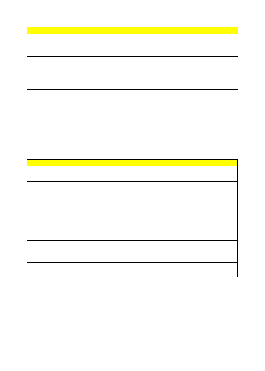
Revision History
Please refer to the table below for the updates made to this service guide.
Date Chapter Updates
II
Page 3

Copyright
Copyright © 2009 by Acer Incorporated. All rights reserved. No part of this publication may be reproduced,
transmitted, transcribed, stored in a retrieval system, or translated into any language or computer language, in
any form or by any means, electronic, mechanical, magnetic, optical, chemical, manual or otherwise, without
the prior written permission of Acer Incorporated.
Disclaimer
The information in this guide is subject to change without notice.
Acer Incorporated makes no representations or warranties, either expressed or implied, with respect to the
contents hereof and specifically disclaims any warranties of merchantability or fitness for any particular
purpose. Any Acer Incorporated software described in this manual is sold or licensed as is. Should the
programs prove defective following their purchase, the buyer (and not Acer Incorporated, its distributor, or its
dealer) assumes the entire cost of all necessary servicing, repair, and any incidental or consequential
damages resulting from any defect in the software.
Acer is a registered trademark of Acer Corporation.
Intel is a registered trademark of Intel Corporation.
Pentium and Pentium II/III are trademarks of Intel Corporation.
Other brand and product names are trademarks and/or registered trademarks of their respective holders.
III
Page 4

Conventions
The following conventions are used in this manual:
SCREEN MESSAGES Denotes actual messages that appear
on screen.
NOTE Gives bits and pieces of additional
information related to the current
topic.
WARNING Alerts you to any damage that might
result from doing or not doing specific
actions.
CAUTION Gives precautionary measures to
avoid possible hardware or software
problems.
IMPORTANT Reminds you to do specific actions
relevant to the accomplishment of
procedures.
IV
Page 5

Preface
Before using this information and the product it supports, please read the following general information.
1. This Service Guide provides you with all technical information relating to the BASIC CONFIGURATION
decided for Acer's global product offering. To better fit local market requirements and enhance product
competitiveness, your regional office MAY have decided to extend the functionality of a machine (e.g.
add-on card, modem, or extra memory capability). These LOCALIZED FEATURES will NOT be covered
in this generic service guide. In such cases, please contact your regional offices or the responsible
personnel/channel to provide you with further technical details.
2. Please note WHEN ORDERING FRU PARTS, that you should check the most up-to-date information
available on your regional web or channel. If, for whatever reason, a part number change is made, it will
not be noted in the printed Service Guide. For ACER-AUTHORIZED SERVICE PROVIDERS, your Acer
office may have a DIFFERENT part number code to those given in the FRU list of this printed Service
Guide. You MUST use the list provided by your regional Acer office to order FRU parts for repair and
service of customer machines.
V
Page 6

VI
Page 7

Table of Contents
System Specifications 1
Features . . . . . . . . . . . . . . . . . . . . . . . . . . . . . . . . . . . . . . . . . . . . . . . . . . . . . . . . . . . .1
System Block Diagram . . . . . . . . . . . . . . . . . . . . . . . . . . . . . . . . . . . . . . . . . . . . . . . . .4
Your Acer Notebook tour . . . . . . . . . . . . . . . . . . . . . . . . . . . . . . . . . . . . . . . . . . . . . . .5
Front View . . . . . . . . . . . . . . . . . . . . . . . . . . . . . . . . . . . . . . . . . . . . . . . . . . . . . . .5
Closed Front View . . . . . . . . . . . . . . . . . . . . . . . . . . . . . . . . . . . . . . . . . . . . . . . . .7
Left View . . . . . . . . . . . . . . . . . . . . . . . . . . . . . . . . . . . . . . . . . . . . . . . . . . . . . . . .8
Right View . . . . . . . . . . . . . . . . . . . . . . . . . . . . . . . . . . . . . . . . . . . . . . . . . . . . . . .9
Rear View . . . . . . . . . . . . . . . . . . . . . . . . . . . . . . . . . . . . . . . . . . . . . . . . . . . . . . .9
Bottom View . . . . . . . . . . . . . . . . . . . . . . . . . . . . . . . . . . . . . . . . . . . . . . . . . . . .10
Indicators . . . . . . . . . . . . . . . . . . . . . . . . . . . . . . . . . . . . . . . . . . . . . . . . . . . . . .11
Easy-Launch Buttons . . . . . . . . . . . . . . . . . . . . . . . . . . . . . . . . . . . . . . . . . . . . .11
Touchpad Basics (with fingerprint reader) . . . . . . . . . . . . . . . . . . . . . . . . . . . . .12
Using the Keyboard . . . . . . . . . . . . . . . . . . . . . . . . . . . . . . . . . . . . . . . . . . . . . . . . . .13
Lock Keys and embedded numeric keypad . . . . . . . . . . . . . . . . . . . . . . . . . . . .13
Windows Keys . . . . . . . . . . . . . . . . . . . . . . . . . . . . . . . . . . . . . . . . . . . . . . . . . .14
Hot Keys . . . . . . . . . . . . . . . . . . . . . . . . . . . . . . . . . . . . . . . . . . . . . . . . . . . . . . .15
Special Key . . . . . . . . . . . . . . . . . . . . . . . . . . . . . . . . . . . . . . . . . . . . . . . . . . . . .16
Using the System Utilities . . . . . . . . . . . . . . . . . . . . . . . . . . . . . . . . . . . . . . . . . . . . . .17
Hardware Specifications and Configurations . . . . . . . . . . . . . . . . . . . . . . . . . . . . . . .18
System Utilities 29
BIOS Setup Utility . . . . . . . . . . . . . . . . . . . . . . . . . . . . . . . . . . . . . . . . . . . . . . . . . . . .29
Navigating the BIOS Utility . . . . . . . . . . . . . . . . . . . . . . . . . . . . . . . . . . . . . . . . .29
Information . . . . . . . . . . . . . . . . . . . . . . . . . . . . . . . . . . . . . . . . . . . . . . . . . . . . .30
Main . . . . . . . . . . . . . . . . . . . . . . . . . . . . . . . . . . . . . . . . . . . . . . . . . . . . . . . . . .31
Security . . . . . . . . . . . . . . . . . . . . . . . . . . . . . . . . . . . . . . . . . . . . . . . . . . . . . . . .32
Boot . . . . . . . . . . . . . . . . . . . . . . . . . . . . . . . . . . . . . . . . . . . . . . . . . . . . . . . . . . .35
Exit . . . . . . . . . . . . . . . . . . . . . . . . . . . . . . . . . . . . . . . . . . . . . . . . . . . . . . . . . . .36
BIOS Flash Utility . . . . . . . . . . . . . . . . . . . . . . . . . . . . . . . . . . . . . . . . . . . . . . . . . . . .37
DOS Flash Utility . . . . . . . . . . . . . . . . . . . . . . . . . . . . . . . . . . . . . . . . . . . . . . . . .38
WinFlash Utility . . . . . . . . . . . . . . . . . . . . . . . . . . . . . . . . . . . . . . . . . . . . . . . . . .40
Remove HDD/BIOS Password Utilities . . . . . . . . . . . . . . . . . . . . . . . . . . . . . . . . . . . .41
Removing BIOS Passwords: . . . . . . . . . . . . . . . . . . . . . . . . . . . . . . . . . . . . . . . .42
Miscellaneous Utilities . . . . . . . . . . . . . . . . . . . . . . . . . . . . . . . . . . . . . . . . . . . . .44
Machine Disassembly and Replacement 47
Disassembly Requirements . . . . . . . . . . . . . . . . . . . . . . . . . . . . . . . . . . . . . . . . . . . .47
General Information . . . . . . . . . . . . . . . . . . . . . . . . . . . . . . . . . . . . . . . . . . . . . . . . . .48
Pre-disassembly Instructions . . . . . . . . . . . . . . . . . . . . . . . . . . . . . . . . . . . . . . .48
Disassembly Process . . . . . . . . . . . . . . . . . . . . . . . . . . . . . . . . . . . . . . . . . . . . .48
External Module Disassembly Process . . . . . . . . . . . . . . . . . . . . . . . . . . . . . . . . . . .49
External Modules Disassembly Flowchart . . . . . . . . . . . . . . . . . . . . . . . . . . . . .49
Removing the Battery Pack . . . . . . . . . . . . . . . . . . . . . . . . . . . . . . . . . . . . . . . .50
Removing the SD Dummy Card . . . . . . . . . . . . . . . . . . . . . . . . . . . . . . . . . . . . .51
Removing the Lower Covers . . . . . . . . . . . . . . . . . . . . . . . . . . . . . . . . . . . . . . . .52
Removing the WLAN Module . . . . . . . . . . . . . . . . . . . . . . . . . . . . . . . . . . . . . . .54
Removing the DIMM Modules . . . . . . . . . . . . . . . . . . . . . . . . . . . . . . . . . . . . . . .56
Removing the Hard Disk Drive Module . . . . . . . . . . . . . . . . . . . . . . . . . . . . . . . .57
Removing the Optical Disk Drive Module . . . . . . . . . . . . . . . . . . . . . . . . . . . . . .59
Main Unit Disassembly Process . . . . . . . . . . . . . . . . . . . . . . . . . . . . . . . . . . . . . . . . .61
Main Unit Disassembly Flowchart . . . . . . . . . . . . . . . . . . . . . . . . . . . . . . . . . . . .61
Removing the Hinge Covers . . . . . . . . . . . . . . . . . . . . . . . . . . . . . . . . . . . . . . . .63
Removing the Switch Cover . . . . . . . . . . . . . . . . . . . . . . . . . . . . . . . . . . . . . . . .64
VII
Page 8

Table of Contents
Removing the Keyboard . . . . . . . . . . . . . . . . . . . . . . . . . . . . . . . . . . . . . . . . . . .66
Removing the Speaker Module . . . . . . . . . . . . . . . . . . . . . . . . . . . . . . . . . . . . . .67
Removing the LCD Module . . . . . . . . . . . . . . . . . . . . . . . . . . . . . . . . . . . . . . . . .69
Removing the Upper Cover . . . . . . . . . . . . . . . . . . . . . . . . . . . . . . . . . . . . . . . .74
Removing the Finger Print Reader . . . . . . . . . . . . . . . . . . . . . . . . . . . . . . . . . . .77
Removing the TouchPad Bracket . . . . . . . . . . . . . . . . . . . . . . . . . . . . . . . . . . . .79
Removing the Media Board . . . . . . . . . . . . . . . . . . . . . . . . . . . . . . . . . . . . . . . .81
Removing the USB Board . . . . . . . . . . . . . . . . . . . . . . . . . . . . . . . . . . . . . . . . . .83
Removing the Modem Module . . . . . . . . . . . . . . . . . . . . . . . . . . . . . . . . . . . . . .85
Removing the Bluetooth Module . . . . . . . . . . . . . . . . . . . . . . . . . . . . . . . . . . . . .86
Removing the Mainboard . . . . . . . . . . . . . . . . . . . . . . . . . . . . . . . . . . . . . . . . . .88
Removing the RJ-11 Port . . . . . . . . . . . . . . . . . . . . . . . . . . . . . . . . . . . . . . . . . .90
Removing the Thermal Module . . . . . . . . . . . . . . . . . . . . . . . . . . . . . . . . . . . . . .92
Removing the CPU . . . . . . . . . . . . . . . . . . . . . . . . . . . . . . . . . . . . . . . . . . . . . . .94
LCD Module Disassembly Process . . . . . . . . . . . . . . . . . . . . . . . . . . . . . . . . . . . . . .95
LCD Module Disassembly Flowchart . . . . . . . . . . . . . . . . . . . . . . . . . . . . . . . . .95
Removing the LCD Bezel . . . . . . . . . . . . . . . . . . . . . . . . . . . . . . . . . . . . . . . . . .96
Removing the Camera Module . . . . . . . . . . . . . . . . . . . . . . . . . . . . . . . . . . . . . .98
Removing the LCD Panel . . . . . . . . . . . . . . . . . . . . . . . . . . . . . . . . . . . . . . . . . .99
Removing the LCD Brackets and Cable . . . . . . . . . . . . . . . . . . . . . . . . . . . . . .101
Removing the Antennas . . . . . . . . . . . . . . . . . . . . . . . . . . . . . . . . . . . . . . . . . .102
Removing the MIC Module . . . . . . . . . . . . . . . . . . . . . . . . . . . . . . . . . . . . . . . .103
LCD Module Reassembly Procedure . . . . . . . . . . . . . . . . . . . . . . . . . . . . . . . . . . . .104
Replacing the MIC Module . . . . . . . . . . . . . . . . . . . . . . . . . . . . . . . . . . . . . . . .104
Replacing the Antennas . . . . . . . . . . . . . . . . . . . . . . . . . . . . . . . . . . . . . . . . . .105
Replacing the LCD Panel . . . . . . . . . . . . . . . . . . . . . . . . . . . . . . . . . . . . . . . . .108
Replacing the Camera Module . . . . . . . . . . . . . . . . . . . . . . . . . . . . . . . . . . . . .110
Replacing the LCD Bezel . . . . . . . . . . . . . . . . . . . . . . . . . . . . . . . . . . . . . . . . .111
Main Module Reassembly Procedure . . . . . . . . . . . . . . . . . . . . . . . . . . . . . . . . . . . .112
Replacing the CPU . . . . . . . . . . . . . . . . . . . . . . . . . . . . . . . . . . . . . . . . . . . . . .112
Replacing the Thermal Module . . . . . . . . . . . . . . . . . . . . . . . . . . . . . . . . . . . . .113
Replacing the RJ-11 Port . . . . . . . . . . . . . . . . . . . . . . . . . . . . . . . . . . . . . . . . .114
Replacing the Mainboard . . . . . . . . . . . . . . . . . . . . . . . . . . . . . . . . . . . . . . . . .115
Replacing the Bluetooth Module . . . . . . . . . . . . . . . . . . . . . . . . . . . . . . . . . . . .116
Replacing the Modem Module . . . . . . . . . . . . . . . . . . . . . . . . . . . . . . . . . . . . .117
Replacing the USB Board . . . . . . . . . . . . . . . . . . . . . . . . . . . . . . . . . . . . . . . . .117
Replacing the Media Board . . . . . . . . . . . . . . . . . . . . . . . . . . . . . . . . . . . . . . . .118
Replacing the TouchPad Bracket . . . . . . . . . . . . . . . . . . . . . . . . . . . . . . . . . . .120
Replacing the Finger Print Reader . . . . . . . . . . . . . . . . . . . . . . . . . . . . . . . . . .120
Replacing the Upper Cover . . . . . . . . . . . . . . . . . . . . . . . . . . . . . . . . . . . . . . . .122
Replacing the LCD Module . . . . . . . . . . . . . . . . . . . . . . . . . . . . . . . . . . . . . . . .125
Replacing the Speaker Module . . . . . . . . . . . . . . . . . . . . . . . . . . . . . . . . . . . . .128
Replacing the Keyboard . . . . . . . . . . . . . . . . . . . . . . . . . . . . . . . . . . . . . . . . . .129
Replacing the Switch Cover . . . . . . . . . . . . . . . . . . . . . . . . . . . . . . . . . . . . . . .130
Replacing the Hinge Covers . . . . . . . . . . . . . . . . . . . . . . . . . . . . . . . . . . . . . . .132
Replacing the ODD Module . . . . . . . . . . . . . . . . . . . . . . . . . . . . . . . . . . . . . . .133
Replacing the Hard Disk Drive Module . . . . . . . . . . . . . . . . . . . . . . . . . . . . . . .134
Replacing the DIMM Modules . . . . . . . . . . . . . . . . . . . . . . . . . . . . . . . . . . . . .134
Replacing the WLAN Module . . . . . . . . . . . . . . . . . . . . . . . . . . . . . . . . . . . . . .135
Replacing the Lower Covers . . . . . . . . . . . . . . . . . . . . . . . . . . . . . . . . . . . . . . .135
Replacing the SD Card Dummy Card . . . . . . . . . . . . . . . . . . . . . . . . . . . . . . . .136
Replacing the Battery . . . . . . . . . . . . . . . . . . . . . . . . . . . . . . . . . . . . . . . . . . . .136
Troubleshooting 137
Common Problems . . . . . . . . . . . . . . . . . . . . . . . . . . . . . . . . . . . . . . . . . . . . . . . . . .137
VIII
Page 9

Table of Contents
Power On Issue . . . . . . . . . . . . . . . . . . . . . . . . . . . . . . . . . . . . . . . . . . . . . . . .138
No Display Issue . . . . . . . . . . . . . . . . . . . . . . . . . . . . . . . . . . . . . . . . . . . . . . . .139
Random Loss of BIOS Settings . . . . . . . . . . . . . . . . . . . . . . . . . . . . . . . . . . . .140
LCD Failure . . . . . . . . . . . . . . . . . . . . . . . . . . . . . . . . . . . . . . . . . . . . . . . . . . . .141
Built-In Keyboard Failure . . . . . . . . . . . . . . . . . . . . . . . . . . . . . . . . . . . . . . . . .141
Touchpad Failure . . . . . . . . . . . . . . . . . . . . . . . . . . . . . . . . . . . . . . . . . . . . . . .142
Internal Speaker Failure . . . . . . . . . . . . . . . . . . . . . . . . . . . . . . . . . . . . . . . . . .142
Internal Microphone Failure . . . . . . . . . . . . . . . . . . . . . . . . . . . . . . . . . . . . . . .144
HDD Not Operating Correctly . . . . . . . . . . . . . . . . . . . . . . . . . . . . . . . . . . . . . .145
ODD Failure . . . . . . . . . . . . . . . . . . . . . . . . . . . . . . . . . . . . . . . . . . . . . . . . . . .146
USB Failure (Rightside) . . . . . . . . . . . . . . . . . . . . . . . . . . . . . . . . . . . . . . . . . .149
Modem Function Failure . . . . . . . . . . . . . . . . . . . . . . . . . . . . . . . . . . . . . . . . . .149
Wireless Function Failure . . . . . . . . . . . . . . . . . . . . . . . . . . . . . . . . . . . . . . . . .150
Bluetooth Function Failure . . . . . . . . . . . . . . . . . . . . . . . . . . . . . . . . . . . . . . . .150
EasyTouch Button Failure . . . . . . . . . . . . . . . . . . . . . . . . . . . . . . . . . . . . . . . . .151
Media Board Failure . . . . . . . . . . . . . . . . . . . . . . . . . . . . . . . . . . . . . . . . . . . . .151
Fingerprint Reader Failure . . . . . . . . . . . . . . . . . . . . . . . . . . . . . . . . . . . . . . . .152
Thermal Unit Failure . . . . . . . . . . . . . . . . . . . . . . . . . . . . . . . . . . . . . . . . . . . . .152
External Mouse Failure . . . . . . . . . . . . . . . . . . . . . . . . . . . . . . . . . . . . . . . . . . .153
Other Failures . . . . . . . . . . . . . . . . . . . . . . . . . . . . . . . . . . . . . . . . . . . . . . . . . .153
Intermittent Problems . . . . . . . . . . . . . . . . . . . . . . . . . . . . . . . . . . . . . . . . . . . . . . . .154
Undetermined Problems . . . . . . . . . . . . . . . . . . . . . . . . . . . . . . . . . . . . . . . . . . . . . .154
Post Codes . . . . . . . . . . . . . . . . . . . . . . . . . . . . . . . . . . . . . . . . . . . . . . . . . . . . . . . .155
Jumper and Connector Locations 161
Top View . . . . . . . . . . . . . . . . . . . . . . . . . . . . . . . . . . . . . . . . . . . . . . . . . . . . . . . . . .161
Bottom View . . . . . . . . . . . . . . . . . . . . . . . . . . . . . . . . . . . . . . . . . . . . . . . . . . . . . . .162
Clearing Password Check and BIOS Recovery . . . . . . . . . . . . . . . . . . . . . . . . . . . .163
Clearing Password Check . . . . . . . . . . . . . . . . . . . . . . . . . . . . . . . . . . . . . . . . .163
BIOS Recovery by Crisis Disk . . . . . . . . . . . . . . . . . . . . . . . . . . . . . . . . . . . . .164
FRU (Field Replaceable Unit) List 165
Aspire 4740/4740G Exploded Diagrams . . . . . . . . . . . . . . . . . . . . . . . . . . . . . . . . .166
Main Module . . . . . . . . . . . . . . . . . . . . . . . . . . . . . . . . . . . . . . . . . . . . . . . . . . .166
Aspire 4740/4740G FRU List . . . . . . . . . . . . . . . . . . . . . . . . . . . . . . . . . . . . . . . . . .167
Screw List . . . . . . . . . . . . . . . . . . . . . . . . . . . . . . . . . . . . . . . . . . . . . . . . . . . . .176
Model Definition and Configuration 178
Aspire 4740 . . . . . . . . . . . . . . . . . . . . . . . . . . . . . . . . . . . . . . . . . . . . . . . . . . . . . . . .178
Aspire 4740G . . . . . . . . . . . . . . . . . . . . . . . . . . . . . . . . . . . . . . . . . . . . . . . . . . . . . .184
Test Compatible Components 199
Microsoft® Windows® 7 Environment Test . . . . . . . . . . . . . . . . . . . . . . . . . . . . . . .200
Online Support Information 205
Index 207
IX
Page 10

Table of Contents
X
Page 11

System Specifications
Features
Below is a brief summary of the computer’s many features:
Operating System
• Genuine Windows® 7™
Platform
• Intel® Core™ i7 processor*
• Intel® Core™ i5 processor*
• Intel® Core™ i3 processor*
• Mobile Intel® HM55 Express Chipset
System Memory
• Dual-Channel SDRAM support
• Up to 4 GB of DDR3 1066 MHz memory, upgradeable to 8 GB using two soDIMM modules
Chapter 1
Display and graphics
• 16:9 aspect ratio
• 14" HD 1366 x 768
• NVIDIA® GeForce® 310M (Aspire 4740G)
• Integrated Intel® GMA HD graphics (Aspire 4740)
Storage subsystem
• 2.5" hard disk drive
• Optical drive option:
• Blu-ray Disc™ /DVD-Super Multi double-layer drive*
• DVD-Super Multi double-layer drive*
• Multi-in-1 card reader
Audio
• Dolby®-optimized surround sound system with two built-in stereo speakers
• True 5.1-channel surround sound output
• High-definition audio support
• S/PDIF (Sony/Philips Digital Interface) support for digital speakers
• Acer PureZone technology with two built-in stereo microphones
• MS-Sound compatible
Chapter 1 1
Page 12

Communication
• Acer Video Conference, featuring:
• Integrated Acer Crystal Eye webcam*
• Acer PureZone technology
• WLAN:
• Intel® Centrino® Advanced-N 6200 802.11a/g/n*
• Acer InviLink™ Nplify™ 802.11b/g/n*
• Acer InviLink™ 802.11b/g*
• WPAN: Bluetooth® 2.1+Enhanced Data Rate (EDR)*
• LAN: Gigabit Ethernet; Wake-on-LAN ready
• Modem: 56K ITU V.92; Wake-on-Ring ready
Dimensions and Weight
• 342 (W) x 239 (D) x 23/38.6 (H) mm (13.4 x 9.4 x 0.9/1.5 inches)
• 2.3Kg (5.07lbs) with 6-cell battery
Privacy control
• Acer Bio-Protection fingerprint solution*
• BIOS user, supervisor, HDD passwords
• Kensington lock slot
Power subsystem
• ACPI 3.0
• 48.8 W 4400 mAh
• 3-pin 65 W AC adapter*
• ENERGY STAR®*
Special keys and controls
• 86-/87-/91-key keyboard
• Touchpad pointing device
I/O interface
• Multi-in-1 card reader (SD/MMC/MS/MS PRO/xD)
• USB 2.0 ports
• HDMI™ port with HDCP support
• External display (VGA) port
• Headphones/speaker/line-out jack with S/PDIF support
• Microphone-in jack
• Line-in jack
• Ethernet (RJ-45) port
• Modem (RJ-11) port
2 Chapter 1
Page 13

• DC-in jack for AC adapter
Environment
• Temperature:
• Operating: 5 °C to 35 °C
• Non-operating: -20 °C to 65 °C
• Humidity (non-condensing):
• Operating: 20% to 80%
• Non-operating: 20% to 80%
NOTE: Items marked with * denote only selected models. The specifications listed above are for reference
only. The exact configuration of your PC depends on the model purchased.
Chapter 1 3
Page 14
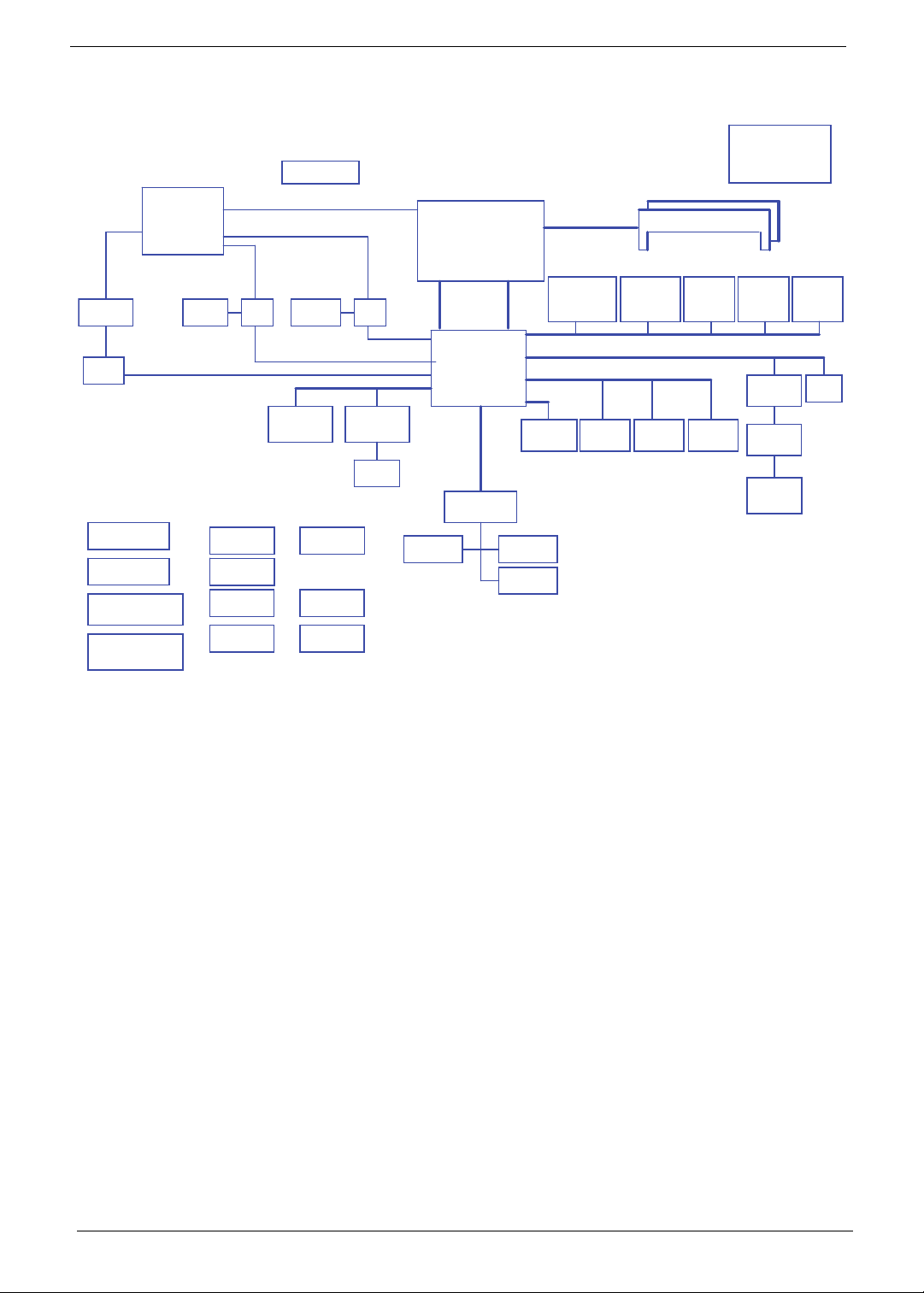
System Block Diagram
Fan Control
page 41
PCI-E 2.0x16 5GT/s PE R LANE
100MHz
PEG(DIS)
LVDS(DIS)
CRT(DIS)
CRT
LVDS Conn.
SW
page 29
PCI-Express x 8 (ABD PCIE1 2.5GT/S CKD PCIE1/2 2. 5/5GT/S)
NAL90 Sub-board
LS-5682P
USB/B
page 35
LS-4493P
Media/B
page 38
LS-5683P
Function/B
page 38
LS-5681P
Finger Printer/B
page 35
page 28
port 2,4 port 1
MINI Card x2
WLAN, TV
page 32
NALG0 Sub-board
LS-5682P
USB/B
page 35
LS-5683P
Function/B
page 38
LS-5681P
Finger Printer/B
page 35
LVDS
SW
page 28
LVDS(UMA)
HDMI(UMA)
LAN(GbE)
BCM57780
page 33
RJ45
page 34
HDMI(DIS)
HDMI Conn.
page 30
Level Shift
page 30
RTC CKT.
Power On/O CKT.
DC/DC Interface CKT.
Power Circuit DC/DC
Nvidia N11MGE1
page
22,23,24,25,26,27
page 8
page 8
page 42
page
CRT Conn.
page 29
133MHz
Auburndale / Clarkseld
(UMA/DIS) (DIS)
(UMA)
100MHz
2.7GT/s
CRT(UMA)
100MHz
Touch Pad
page 38
Intel
Processor
rPGA988A
page 4,5,6,7,8,9
Intel
Ibex Peak-M
PCH
page 13,14,15,16,17
18,19,20,21
LPC BUS
33MHz
ENE KB926
page 37
Memory BUS(DDRIII)
Dual Channel
1.5V DDRIII 800/1066/1333
USB conn x2
DMI x4FDI x8
USB port 8 HS
USB Port 2 (eSATA)
USB port 0 (sub board)
100MHz
1GB/s x4
USBx14
HD Audio
SATA x 6 (GEN1 1.5GT/S ,GEN2 3GT/S)
SPI
SPI ROM x2
page 13
Int.KBD
page 38
BIOS ROM
page 38
6.4G/8.5G/10.6G
100M/133M/166M(CFD)
3.3V 48MHz
3.3V 24MHz
port 0
SATA HDD
Conn.
page 31
204pin DDRIII-SO-DIMM X2
BANK 0, 1, 2, 3
page 35
100MHz
SATA ODD
Conn.
page 31
port 1
CMOS
Camera
USB port 3
eSATA
Conn.
page 35
2 egap53 egap
port 4
Bluetooth
Conn
USB port 10
Clock Generator
IDT: 9LRS3199AKLFT
SILEGO: SLG8SP587
133/120/100/96/14.318MHZ to PCH
48MHZ to CardReader
page 10,11
Finger
Printer
USB port 11
8
page 35
HDA Codec
ALC888
page 40
Audio AMP
APA2051
page 41
Int. Speaker
page 41
page 12
Card
Reader
USB port 6
page 36
page 39
MDC
4 Chapter 1
Page 15
Your Acer Notebook tour
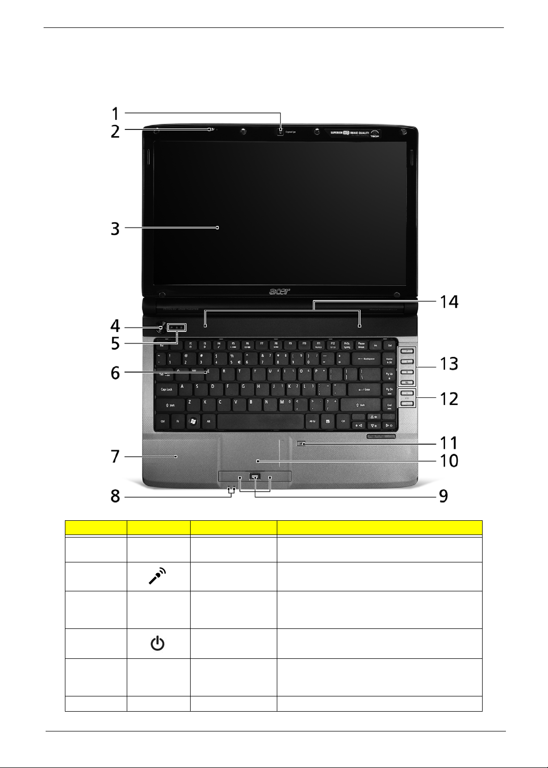
Front View
No. Icon Item Description
1 Acer Crystal Eye
webcam
2 Microphone Internal microphone for sound recording.
3 Display screen Also called Liquid-Crystal Display (LCD),
4 Power button Turns the computer on and off.
5 Status indicators Light-Emitting Diodes (LEDs) that light up to
6 Keyboard For entering data into your computer.
Chapter 1 5
Web camera for video communication (only for
certain models).
displays computer output (Configuration may
vary by models).
show the status of the computer's functions
and components.
Page 16
No. Icon Item Description
7 Palmrest Comfortable support area for your hands when
you use the computer.
8 Status indicators Light-Emitting Diodes (LEDs) that light up to
show the status of the computer's functions
and components.
9 Click buttons
(left, center* and
right)
10 T ouchpad T ouch-sensitive pointing device which functions
1 1 Touchpad Toggle Turns the internal touchpad on and off.
The left and right buttons function like the left
and right mouse buttons.
*The center button serves as Acer BioProtection fingerprint reader supporting Acer
FingerNav 4-way control function (only for
certain models).
like a computer mouse.
12 Volume Up/
Volume Down
13 Programmable
P
14 Speakers Left and right speakers deliver stereo audio
key
Backup key Launches Acer Backup Management for
Wireless LAN
communication
button/indicator
Bluetooth
communication
button/indicator
Increase system volume/decrease system
volume.
User-programmable.
three-step data backup.
Enables/disables the wireless LAN
function. Indicates the status of wireless
LAN communication.
Enables/disables the Bluetooth function.
Indicates the status of Bluetooth
communication. (only for certain models)
output.
6 Chapter 1
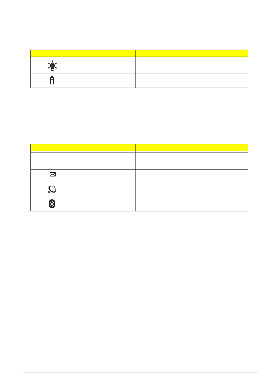
Page 17
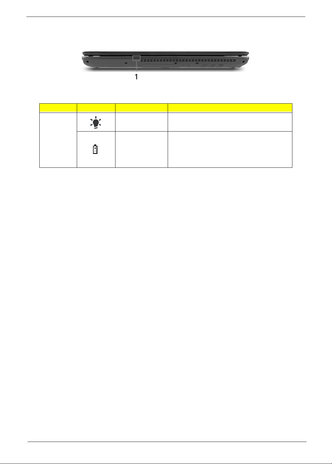
Closed Front View
No. Icon Item Description
1 Power Indicates the computer’s power status.
Battery Indicates the computer’s battery status.
1. Charging: The light shows amber when the
battery is charging.
2. Fully charged: The light shows blue when in
AC mode.
Chapter 1 7
Page 18
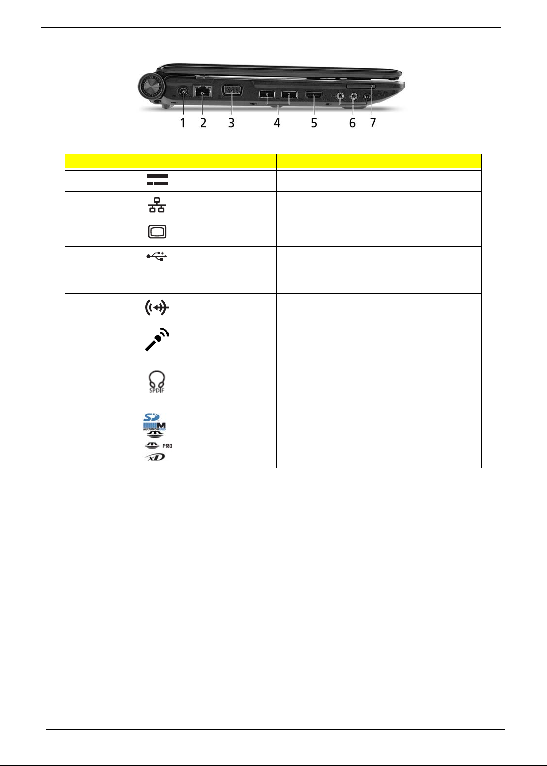
Left View
No. Icon Item Description
1 DC in jack Connects to an AC adapter
2 Ethernet (RJ-45)
port
3 External display
(VGA) port
4
5
6 Line-in jack Accepts audio line-in devices (e.g., audio CD
7 Multi-in-1 card
HDMI
USB 2.0 Connects to USB 2.0 devices.
HDMI port Supports high definition digital video
Microphone jack Accepts inputs from external microphones.
Headphones/
speaker/line-out
jack with S/PDIF
support
reader
Connects to an Ethernet 10/100/1000-based
network.
Connects to a display device
(e.g. external monitor, LCD projector).
connections.
player, stereo walkman, mp3 player).
Connects to audio line-out devices
(e.g., speakers, headphones).
Accepts Secure Digital (SD), MultiMediaCard
(MMC), Memory Stick (MS), Memory Stick Pro
(MS PRO), and xD-Picture Card.
Note: Push to remove/install the card. Only
one card can operate at any given time.
8 Chapter 1
Page 19
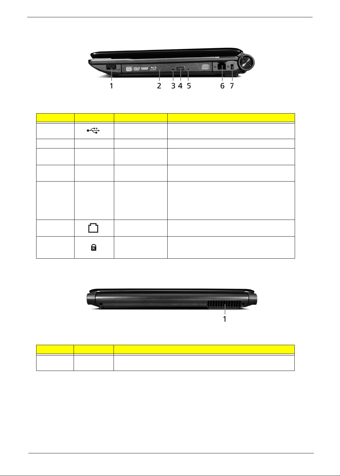
Right View
No. Icon Item Description
1 USB 2.0 port Connect to USB 2.0 devices (e.g. USB mouse,
USB camera).
2 Optical drive Internal optical drive; accepts CDs or DVDs.
3 Optical disk access
indicator
4 Optical drive eject
button
5 Emergency eject
hole
6 Modem (RJ-11)
port
7 Kensington lock
slot
Lights up when the optical drive is active.
Ejects the optical disk from the drive.
Ejects the optical drive tray when the computer is
turned off.
Note: Insert a paper clip into the emergency eject
hole to eject the optical drive tray when the
computer is off.
Connects to a phone line.
Connects to a Kensington-compatible computer
security lock.
Rear View
No. Item Description
1 Ventilation
slots
Enable the computer to stay cool, even after prolonged use.
Chapter 1 9
Page 20
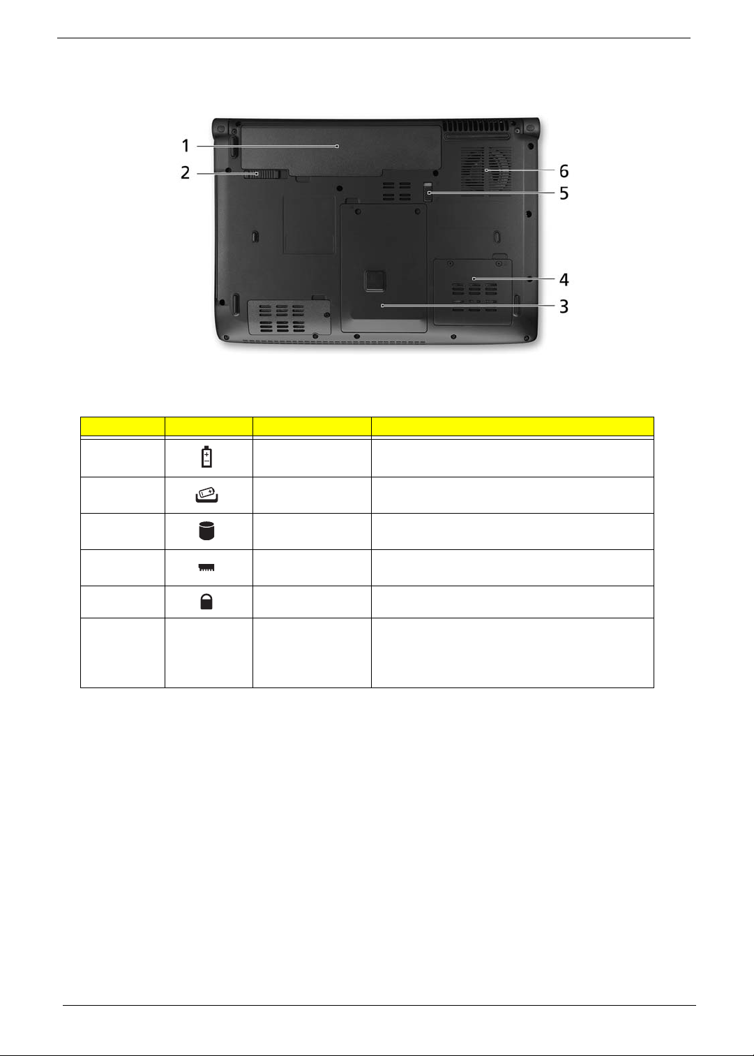
Bottom View
No. Icon Item Description
1 Battery bay Houses the computer's battery pack.
2 Battery release
latch
3 Hard disk bay Houses the computer's hard disk (secured with
4 Memory
compartment
5 Battery lock Locks the battery in position.
6 Ventilation slots
and cooling fan
Releases the battery for removal.
screws).
Houses the computer's main memory.
Enables the computer to stay cool, even after
prolonged use.
Note: Do not cover or obstruct the opening of the
fan.
10 Chapter 1
Page 21
Indicators
The computer has several easy-to-read status indicators:
The front panel indicators are visible even when the computer cover is closed.
Icon Function Description
Power Indicates the computer's power status.
Battery Indicates the computer's battery status.
NOTE: 1. Charging: The battery light show s amber when the battery is charging. 2. Fully charged: The light
shows green when in AC mode.
Easy-Launch Buttons
Located beside the keyboard are application buttons. These buttons are called easy-launch buttons. They are:
Programmable, Backup, Wireless LAN, and Bluetooth.
To set the programmable key, run the Acer Launch Manager.
Icon Function Description
Programmable key User-Programmable.
P
Backup key Launches Acer Backup Management for three-step
data backeup.
Wireless communication
switch
Bluetooth communication
switch
Enables/disables the wireless function.
Enables/disables the Bluetooth function.
Chapter 1 11
Page 22
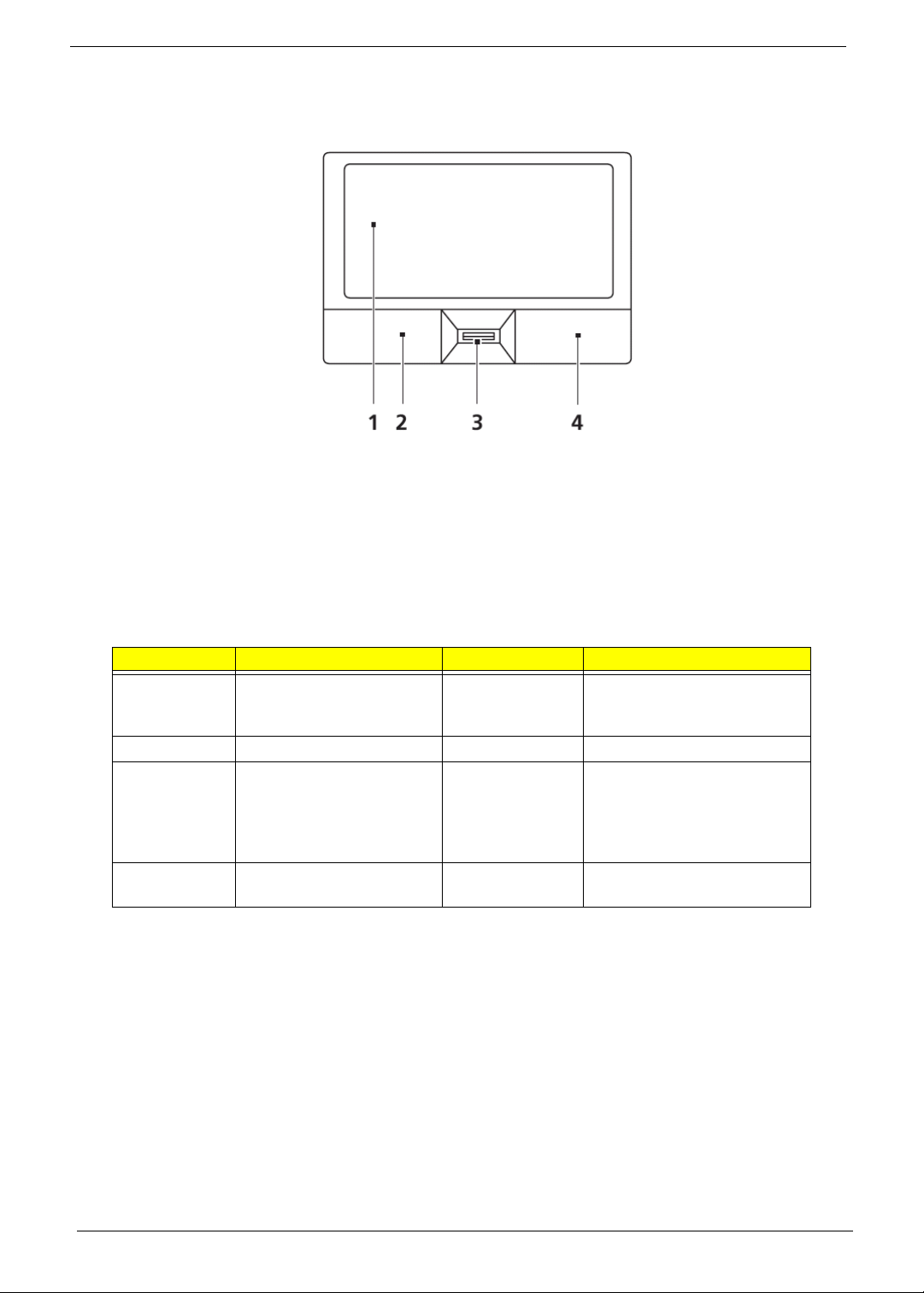
Touchpad Basics (with fingerprint reader)
The following items show you how to use the touchpad with Acer Bio-Protection fingerprint reader:
• Move your finger across the touchpad (1) to move the cursor.
• Press the left (2) and right (4) buttons located beneath the touchpad to perform selection and
execution functions. These two buttons are similar to the left and right buttons on a mouse.
Tapping on the touchpad is the same as clicking the left button.
• Use Acer Bio-Protection fingerprint reader (3) supporting Acer FingerNav 4-way control function
(only for certain models) or the 4-way scroll (3) button (only for certain models) to scroll up or down
and move left or right a page. This fingerprint reader or button mimics your cursor pressing on the
right scroll bar of Windows applications.
Function Left Button (2) Right Button (4) Main touchpad (1)
Execute Quickly click twice. Tap twice (at the same speed
as double-clicking a mouse
button).
Select Click once. Tap once.
Drag Click and hold, then use
finger on the touchpad to
drag the cursor.
Tap twice (at the same speed
as double-clicking a mouse
button); rest your finger on
the touchpad on the second
tap and drag the cursor.
Access
Click once.
context menu
NOTE: When using the touchpad, keep it - and your fingers - dry and clean. The touchpad is sensitive to finger
movement; hence, the lighter the touch, the better the response. Tapping too hard will not increase the
touchpad’s responsiveness.
12 Chapter 1
Page 23
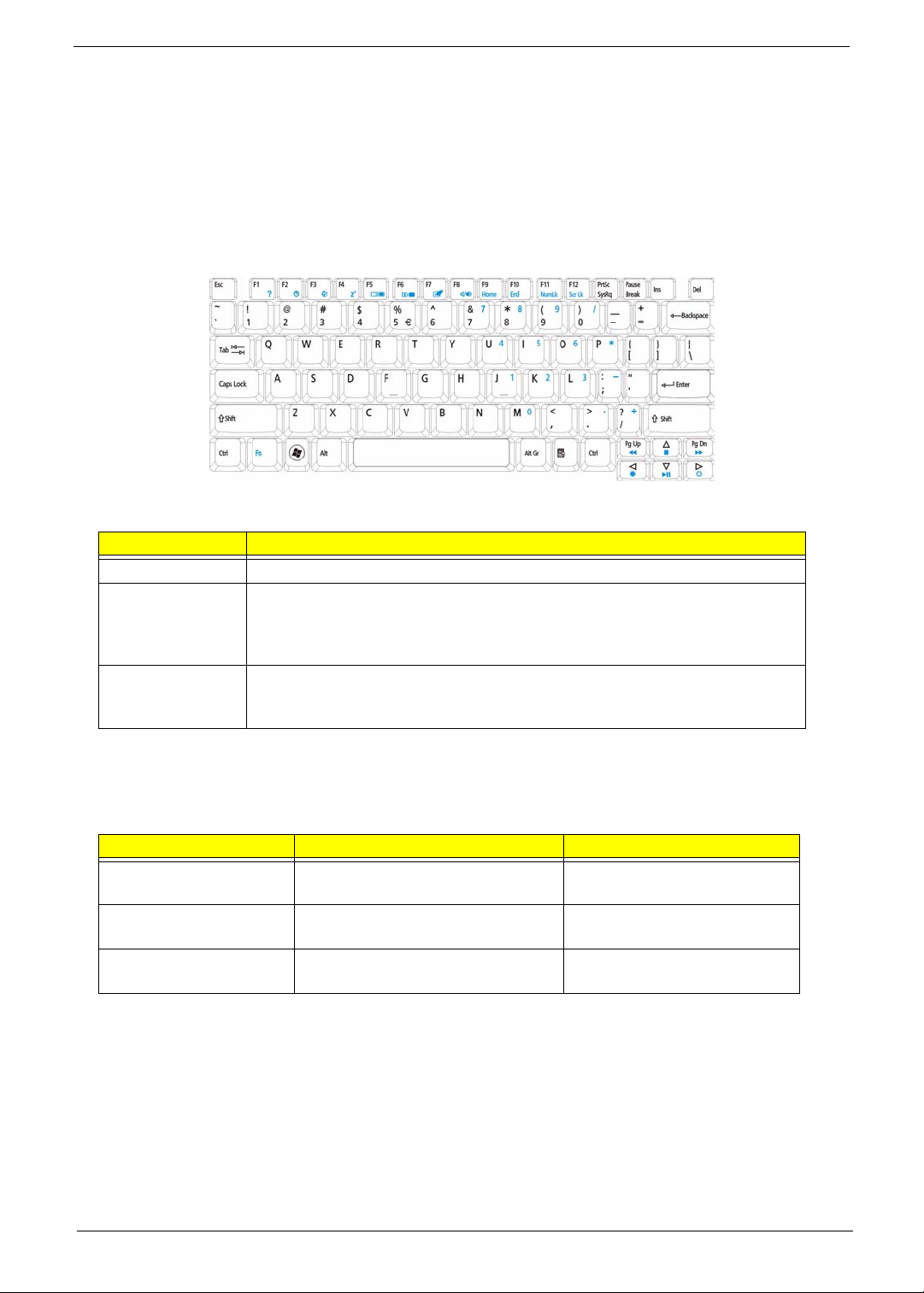
Using the Keyboard
The keyboard has full-sized keys and an embedded numeric keypad, separate cursor, lock, Windows, function
and special keys.
Lock Keys and embedded numeric keypad
The keyboard has three lock keys which you can toggle on and off.
Lock key Description
Caps Lock When Caps Lock is on, all alphabetic characters typed are in uppercase.
Num Lock
<Fn> + <F11>
Scroll Lock <Fn> +
<F12>
When Num Lock is on, the embedded keypad is in numeric mode. The keys
function as a calculator (complete with the arithmetic operators +, -, *, and /). Use
this mode when you need to do a lot of numeric data entry. A better solution
would be to connect an external keypad.
When Scroll Lock is on, the screen moves one line up or down when you press
the up or down arrow keys respectively. Scroll Lock does not work with some
applications.
The embedded numeric keypad functions like a desktop numeric keypad. It is indicated by small characters
located on the upper right corner of the keycaps. To simplify the keyboard legend, cursor-control key symbols
are not printed on the keys.
Desired access Num Lock on Num Lock off
Number keys on
embedded keypad
Cursor-control keys on
embedded keypad
Main keyboard keys Hold <Fn> while typing letters on
Type numbers in a normal manner.
Hold <Shift> while using cursorcontrol keys.
embedded keypad.
Hold <Fn> while using cursorcontrol keys.
Type the letters in a normal
manner.
Chapter 1 13
Page 24
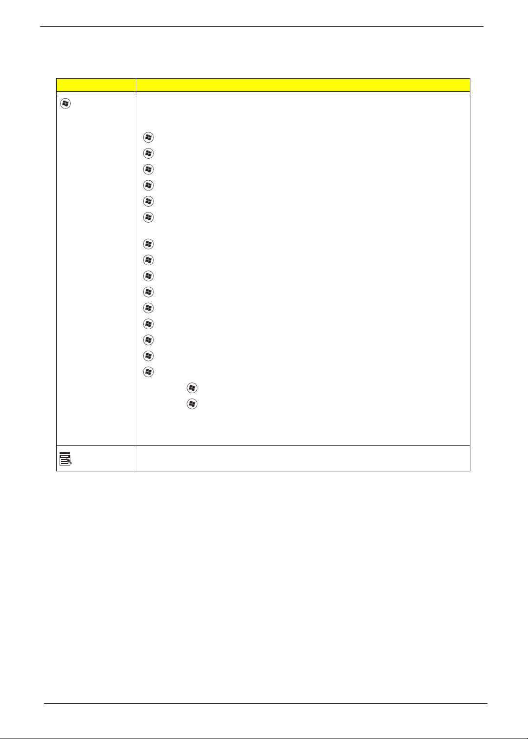
Windows Keys
The keyboard has two keys that perform Windows-specific functions.
Key Description
Windows key Pressed alone, this key has the same effect as clicking on the Windows Start button;
it launches the Start menu. It can also be used with other keys to provide a variety of
functions:
<>: Open or close the S tart menu
<> + <D>: Display the desktop
<> + <E>: Open Windows Explore
<> + <F>: Search for a file or folder
<> + <G>: Cycle through Sidebar gadgets
<> + <L>: Lock your computer (if you are connected to a network domain), or
switch users (if you're not connected to a network domain)
<> + <M>: Minimizes all windows
<> + <R>: Open the Run dialog box
<> + <T>: Cycle through programs on the taskbar
<> + <U>: Open Ease of Access Center
<> + <X>: Open Windows Mobility Center
<> + <BREAK>: Display the System Properties dialog box
<> + <SHIFT+M>: Restore minimized windows to the desktop
<> + <TAB>: Cycle through programs on the taskbar by using Windows Flip 3-D
<> + <SPACEBAR>: Bring all gadgets to the front and select Windows Sidebar
Application
key
<CTRL> +
<CTRL> + <> + <TAB>: Use the arrow keys to cycle through programs on the
Note: Depending on your edition of Windows 7, some shortcuts may not function as
This key has the same effect as clicking the right mouse button; it opens the
application's context menu.
<> + <F>: Search for computers (if you are on a network)
taskbar by using Windows Flip 3-D
described.
14 Chapter 1
Page 25
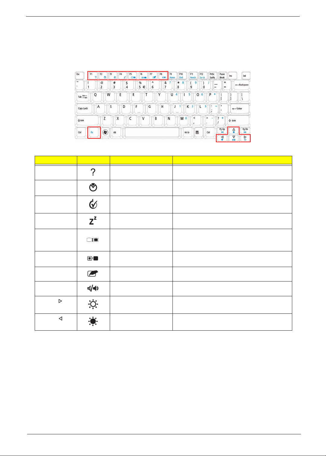
Hot Keys
The computer employs hotkeys or key combinations to access most of the computer’s controls like screen
brightness, volume output and the BIOS utility.
To activate hot keys, press and hold the <Fn> key before pressing the other key in the hotkey combination.
Hotkey Icon Function Description
<Fn> + <F1> Hotkey help Displays help on hotkeys.
<Fn> + <F2> Acer eSettings
Management
<Fn> + <F3> Acer ePower
Management
<Fn> + <F4> Sleep Puts the computer in Sleep mode.
<Fn> + <F5> Display toggle Switches display output between the display
<Fn> + <F6> Screen blank Turns the display screen backlight off to save
<Fn> + <F7> Touchpad toggle Turns the internal touchpad on and off.
<Fn> + <F8> Speaker toggle Turns the speakers on and off.
<Fn> + < > Brightness up Increases the screen brightness.
<Fn> + < > Brightness down Decreases the screen brightness.
Launches Acer eSettings Management in Acer
Empowering Technology.
Launches Acer ePower Management in Acer
Empowering Technology.
screen, external monitor (if connected) and
both.
power. Press any key to return.
Chapter 1 15
Page 26
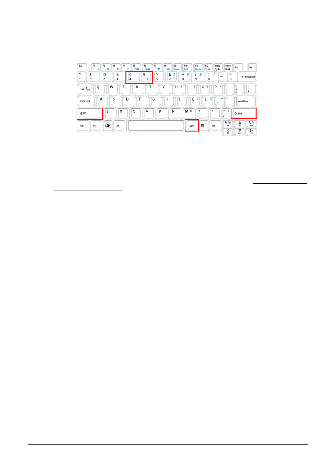
Special Key
You can locate the Euro symbol and the US dollar sign at the upper-center and/or bottom-right of your
keyboard.
The Euro symbol
1. Open a text editor or word processor.
2. Hold <Alt Gr> and then press the <5> key at the upper-center of the keyboard.
NOTE: Note: Some fonts and software do not support the Euro symbol. Please refer to www.microsoft.com/
typography/faq/faq12.htm for more information.
The US dollar sign
1. Open a text editor or word processor.
2. Hold <Shift> and then press the <4> key at the upper-center of the keyboard.
NOTE: This function varies by the operating system version.
16 Chapter 1
Page 27
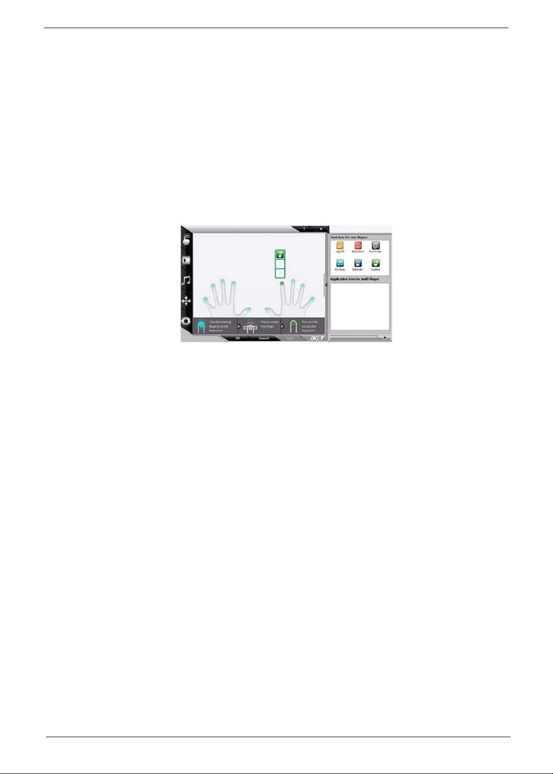
Using the System Utilities
Acer Bio-Protection (only for certain models) Acer Bio-Protection Fingerprint Solution is a multi-purpose
fingerprint software package integrated with the Microsoft Windows operating system. Utilizing the uniqueness
of one's fingerprint features, Acer Bio-Protection Fingerprint Solution has incorporated protection against
unauthorized access to your computer with centralized password management with Password Bank, easy
music player launching with Acer MusicLaunch, secure Internet favorites via Acer MyLaunch, and fast
application/website launching and login with Acer FingerLaunch, while Acer ProfileLaunch can launch up to
three applications/websites from a single finger swipe.
Acer Bio-Protection Fingerprint Solution also allows you to navigate through web browsers and documents
using Acer FingerNav. With Acer Bio-Protection Fingerprint Solution, you can now enjoy an extra layer of
protection for your personal computer, as well as the convenience of accessing your daily tasks with a simple
swipe of your finger!
For more information refer to the Acer Bio-Protection help files.
Chapter 1 17
Page 28
Hardware Specifications and Configurations
Processor
Item Specification
CPU Type Intel® Mobile Calpella Arrandale CPU
Core Logic
CPU Package mPGA-989
CPU Core
Voltage
Processor Specifications
Processor
#
Ci3330M 2.13 GHz 2 1.6 3 MB mPGA-989 35 W KC.33001.DMP
Ci3350M 2.26 GHz 2 2.5 3 MB mPGA-989 35 W KC.35001.DMP
Ci5430M 2.26 GHz 2-4 2.5 3 MB mPGA-989 35 W KC.43001.DMP
Ci5520M 2.4 GHz 2-4 2.5 3 MB mPGA-989 35 W KC.52001.DMP
Ci5540M 2.53 GHz 2-4 2.5 3 MB mPGA-989 35 W KC.54001.DMP
Ci7620M 2.66 GHz 4 N/A 4 MB mPGA-989 35 W KC.62001.DMP
• Two execution cores
• A 32-KB instruction and 32-KB data first-level cache (L1) for each core
• A 256-KB shared instruction/data second-level cache (L2) for each core
• Up to 4-MB shared instruction/data third-level cache (L3), shared among all
cores
Refer to table below
CPU
Speed
Cores
Bus
Speed
GT/s
Cache
Size
Package
Core
Voltage
Acer P/N
System Board Major Chips
Item Specifications
Core logic Intel Ibex Peak-M (HM55)
Keyboard Controller ENE KB926 for Keyboard Controller, Battery management Unit, and RTC
LAN Broadcom BCM57780A1KMLG for Giga LAN
Media Card Reader Realtek RTS5159 for Card Reader, 7 in 1 controller
Audio Codec Realtek ALC888S-VC for High Definition Audio Codec with Dolby Digital Live
CPU Fan True Value Table (DIS)
CPU Temperature (°C)
Core 0 Core 1 Core 2 Core 3
Fan Speed
(rpm)
SPL Spec
(dBA)
45 45 45 45 2900 28
55 55 55 55 3200 31
60 60 60 60 3500 34
68 68 68 68 3900 37
85 85 85 85 4200 40
99 99 99 99 4200 40
• Throttling 50%: On =99°C; Off=89°C
• OS Shut down: 104°C
• H/W Shut down: 92°C
18 Chapter 1
Page 29
CPU Fan True Value Table (UMA)
CPU Temperature (°C)
Core 0 Core 1 Core 2 Core 3
Fan Speed
(rpm)
40 40 40 40 2900 28
45 45 45 45 3200 31
50 50 50 50 3500 34
60 60 60 60 3900 37
80 80 80 80 4200 40
99 99 99 99 4200 40
• Throttling 50%: On =99°C; Off=89°C
• OS Shut down: 104°C
• H/W Shut down: 92°C
BIOS ROM
Item Specification
BIOS Vendor Insyde H20
BIOS Version V0.09
BIOS ROM Type Flash ROM
BIOS ROM Size 4 MB
Supported Protocols
• Support ISIPP
• Support Acer UI
• Support multi-boot
• Suspend to RAM (S3)/Disk (S4)
• Va rious hot-keys for system control
• Support SMBIOS 2.3 ,PCI2.2.
• Refer to Acer BIOS specification.
• DMI utility for BIOS serial number configurable/asset tag
• Support PXE
• Support WinFlash
• Wake on LAN from S3
• Wake on LAN form S4 in AC mode
BIOS Password control Supervisor, User, and HDD
SPL Spec
(dBA)
Chapter 1 19
Page 30
System Memory
Item Specifications
Memory Controller Onboard
Memory Size 0MB (No on-board Memory)
DIMM socket number 2 sockets
Supports Memory size
per socket
Support maximum
memory size
Support DIMM type DDR III Sync hronous DRAM
Support DIMM Speed 800/1066 MHz
Support DIMM voltage 1.5V
Support DIMM
package
Cache 6MB L2 on CPU
VGA Memory 512 MB with optional adjustable 128MB UMA VGA memory share from North
Memory module
combinations
Memory Combinations
Slot 1 Slot 2 Total Memory
0MB 512MB 512MB
0MB 1024MB 1024MB
0MB 2048MB 2048MB
512MB 512MB 1024MB
512MB 1024MB 1536MB
512MB 2048MB 2560MB
1024MB 0MB 1024MB
1024MB 512MB 1536MB
1024MB 1024MB 2048MB
1024MB 2048MB 3072MB
2048MB 0MB 2048MB
2048MB 512MB 2560MB
2048MB 1024MB 3072MB
2048MB 2048MB 4096MB
4096MB 4096MB 8192MB
4 GB
8 GB for 64bit OS (with two 2GB SO-DIMM)
204-pin DDR III-800/1066 SO-DIMM
Bridge
Y ou can inst all memory modu les in any combination as long as they match the
above specifications
NOTE: Above table lists some system memory configurations. You may combine DIMMs with various
capacities to form other combinations. On above table, the configuration of slot 1 and slot 2 could be
reversed.
20 Chapter 1
Page 31

Hard Disk Drive Interface
Item Specifications
Vendor &
Model Name
Capacity
Seagate
ST9250827AS
250 320, 160 500 320, 250, 160 500, 320, 250,
Seagate
ST9320320AS
ST9160310AS
Seagate
ST9500325AS
(MB)
Bytes per
512 512 512 512 512
sector
Data heads
4 4, 2 4 4, 4, 2 4, 3, 2, 2
Drive Format
Disks
Spindle speed
2 2 or 1, 1 2 2, 2, 1 2, 2, 1, 1
5400 5400 5400 5400 5400
(RPM)
Performance Specifications
Buffer size
Interface
Internal
8 MB 8 MB 8 MB 8 MB 8 MB
SATA SATA SATA SATA SATA
778 352 1,175 400 ~ 794
transfer rate
(Mbits/sec,
max)
I/O data
300 150 300 300 300 maximum
transfer rate
(Mbytes/sec
max)
DC Power Requirements
Voltage
5V ±5% 5V ±5% 5V ±5% 5V ±5% 5V ±5%
Toshiba
MK3252GSX
MK2552GSX
MK1652GSX
typical
WD
WD5000BEVT
WD3200BEVT
WD2500BEVT
WD1600BEVT
160
106 Mbits/s
maximum
Chapter 1 21
Page 32

Super-Multi Combo Module
Item Specification
Vendor & model name Philips DS-8A2S, Toshiba Digi/TS-L633A
Performance S p ecification With CD Diskette With DVD Diskette
Transfer rate (MB/sec) Sustained:
Max 3.5 Mbytes/sec
Buffer Memory 2MB
Interface SATA
Applicable disc format Applicable media types:
Writing:
Confirms to DVD+R Version 1.2 and DVD+RW Version 1.3 / DVD+R DL
Version 1.0 /DVD-R Version 2.0 / DVD-RW Version 1.2 / DVD-R DL Version
3.0.
Reading:
DVD single/dual layer (PTP, OTP), DVD-R single/dual layer
DVD+R single/double layer
DVD-RW
DVD+RW
CD-DA
CD-ROM
CD-ROM/XA
Photo-CD, Multi-session, Video CD
CD-I FMV, CD Extra, CD Plus, CD-R, and CD-RW
Loading mechanism Drawer (Solenoid Op en)
Tact SW (Open)
Emergency Release (draw open hole)
Power Requirement
Input Voltage DC 5 V +/- 5%
Sustained:
Max 10 Mbytes/sec
22 Chapter 1
Page 33

Super-Multi Combo Module (continued)
Item Specification
Vendor & model name HLDS GT10N Sony AD7580S
Performance
Specification
Transfer rate (MB/sec) Sustained:
Buffer Memory 2 MB
Interface SATA
Applicable disc formats
Loading mechanism Drawer (Solenoid Open)
Power Requirement
Input Voltage DC 5 V +/- 5%
With CD Diskette With DVD Diskette With CD Diskette With DVD Diskette
Sustained:
1,571 (typical)
3,600 KB/s (24x) max.
Sustained:
11.08 Mbytes/s (8x)
max.
• DVD-ROM:
• 4.7GB (Single Layer)
• 8.5GB (Dual Layer)
• DVD-R:
• 3.95GB (Ver. 1.0: read only)
• 4.7GB (Ver. 2.0 for Authoring: read
only)
• 4.7GB (Ver. 2.1 for General: read &
write)
• (DL) 8.5GB (Ver. 3.0)
• DVD-RW:
• 4.7GB (Ver. 1.2/ Rev 1.0, 2.0, 3.0)
• DVD-RAM: 1.46GB/side, 4.7GB/side (Ver.
2.2)
• DVD+R: 4.7GB (Ver. 1.3)
• (DL) 8.5GB (Ver. 1.1)
• DVD+RW:
• 4.7GB (Vol.1 Ver.1.3)
DVD Read:
DVD-ROM (DVD-5, DVD-9, DVD-10, DVD-18),
DVD-Video, DVD-Audio, SACD (Hybrid),
UDF DVD, DVD-R, DVD-R DL, DVD-R 3.95 GB,
DVD-R Authoring, DVD-R Multi-Border,
DVD-RW, DVD+R, DVD+R DL, DVD+R MultiSession, DVD+RW, DVD-RAM V1.0, DVDRAM
V2.0 & 2.1 &2.2.
CD Read:
CD-DA, CD-ROM Mode-1, CD-ROM/XA Mode-2
Form-1 and Mode-2 Form-2, CD-i, CD-i
Bridge, Video-CD (MPEG-1), Karaoke CD, PhotoCD, Enhanced CD, CD Plus, CD Extra, itrax
CD, CD-Text, UDF CD, CD-R, and CD-RW
DVD Write:
DVD Data & Video
CD Read:
• CD-ROM Mode-1 data disc
• CD-ROM Mode-2 data disc
• CD-ROM XA, CD-I, Photo-CD Multi-
CD-DA, CD-ROM Mode-1, CD-ROM/XA Mode-2
Form-1 and Mode-2 Form-2, CD-i, Video-
CD, CD-Text
Session, Video CD
• CD-Audio Disc
• Mixed mode CD-ROM disc (data and
audio)
• CD-Extra
• CD-Text
• CD-R (Conforming to “Orange Book Part
2”: read & write)
• CD-RW (Conforming to “Orange Book Part
3”: read & write)
Tact SW (Open)
Emergency Release (draw open hole)
Sustained:
10,993 (typical)
Chapter 1 23
Page 34

Blueray Combo Drive
Item Specification
Manufacturer and Model Sony NEC Optiarc BC-5500S-AR
Type Drawer loading
Interface SATA
Data Transfer Modes
• PIO mode
• DMA
• Ultra DMA33
Buffer Memory Size 4.5 MB
Maximum Write Speed 11 Mbytes/sec
Maximum Read Speed 9 Mbytes/sec
Formats Supported Read
• BD-Video (12cm, Single and Dual Layer), BD-ROM (12cm, Single
and Dual Layer)
• DVD-Video (8cm/12cm, Single and Dual Layer), DVD-ROM (8cm/
12cm, Single and Dual Layer), Multi-Boarder, Multi-Session
CD Write
• CD-R Media (48x/40x/32x/24x/16x/8x) Mitsubishi (Verbatim), Taiyo-
Yuden, Mitsui, Ricoh, Fuji film, Sony, Hitachi Maxell, Memorex,
RITEK, CMC, P.V.C, JVC, SKC, ACER, Prime Disc, TDK
• CD-RW Media (10x/4x) Ricoh, Mitsubishi (Verbatim), ACER,
OPTROM, Memorex, P.V.C, RITEK, CMC, LEADDA TA, GigaStorage,
Prodisc, Fornex, Samsung, Philips
DVD Write
• DVD+R Media (16x/8x/4x/2.4x) Taiyo-Yuden, Mitsubishi (Verbatim),
Ricoh, TDK
• DVD+R Double Layer Media (8x/2.4x) Mitsubishi (Verbatim)
• DVD+RW Media (8x/4x/2.4x) Mitsubishi (Verbatim), Ricoh, TDK
• DVD-R Media (16x/8x/4x/2x) Mitsubishi (Verbatim), TDK, Taiyo-
Yuden, PVC, Fuji Film, Ritek
• DVD-R DL Media (8x/4x) Mitsubishi (Verbatim)
• DVD-RW Media (6x/4x/2x/1x) JVC, PVC, Mitsubishi (Verbatim), TDK
• DVD-RAM Ver2.2 Media (5x/3x/2x) Panasonic, Hitachi Maxell
Power Supply +5V (DC)
Voltage Allowance +5V (DC) ±5%
24 Chapter 1
Page 35

LCD 14”
Item Specification
Vendor/model name
• Samsung LTN140AT01-G01
• AUO B140XW01
• LG LP140WH1
• CMO N140B6 - L02
Screen Diagonal (mm) 355.6 (14.0”)
Display Area (mm) 309.399(H) X 173.952(V)
Display resolution (pixels) 1366 x 768
Pixel Pitch 0.2265(H) x 0.2265(V)
Display Mode Normally white
2
220 (typ.)
Typical White Luminance (cd/m
)
(also called Brightness)
Contrast Ratio (typical) 500
Response Time (Optical Rise
8 (typ.)
Time/Fall Time) msec
Input Voltage 3.3V ±0.3V
Typical Power Consumption
5W (max.)
(watt)
Weight 375g (max.)
Physical Size (mm) 324.0(H) x 192.5(V) x 5.2(D)
Electrical Interface LVDS
Support Color 262,144
Viewing Angle (degree) Min. Typ.
Horizontal
Vertical 10 15
CR => 10
40 45
40 45
25 30
Temperature Range (°C)
Operating
Storage (shipping)
0 to 50°C
-20 to 60°C
Chapter 1 25
Page 36

VGA Graphic Controller
Item Specification
Type Intel built in VGA chip (Aspire 4740)
Nvidia (Aspire 4740G)
Processor Cores 128
Graphics Clock 1836 MHz
Texture Fill Rate 47.2 (billion/sec)
Memory Interface
Width
Memory Bandwidth 64 (GB/sec)
Maximum VGA
Resolution
Keyboard
Item Specification
Keyboard Controller ENE KB926
Total number of keypads 86-/87-/91-key
Windows logo key Yes
Internal & external keyboard work
simultaneously
Media Card Reader
Item Specification
Type Realtek RTS5159
256-bit
2048x1536
Yes
26 Chapter 1
Page 37

Item Specification
Features • Compliant with Universal Serial Bus Specification Revision 2.0
• Compliant with USB Mass Storage Class Bulk only Transport S pecification
Rev. 1.0
• Support High-speed (480Mbps) and Full-speed (12Mbps) Data Transfer
• USB bus power operation
• Support Control, Bulk IN / OUT data pipes
• Support the following memory card interfaces:
• Secure Digital TM (SD), MultiMediaCard TM (MMC), Mini-SD, Micro-SD
(T-flash), RS-MMC,
• Mobile-MMC and MMC-micro
• Memory Stick TM (MS), Memory Stick PROTM (MS-PRO), MS Duo, MS-
PRO Duo and Micro-MS (M2)
• MSPRO-HG Duo 8-bit mode
• xD-Picture Card TM (xD) including Type M and Type H
• Support hardware ECC (Error Correction Code) function
• Support hardware CRC (Cyclic Redundancy Check) function
• Programmable clock rate for flash memory card interfaces
• Support MS-PRO v1.02
• Support MS v1.43
• Support MS PRO-HG Duo v1.01
• Support SD version 2.0
• Support MMC version 4.2
• Support xD v1.2
• Integrated Fast 8051 microprocessor
• External serial EEPROM interface
• 12MHz crystal oscillator with integrated PLL
• Support 48Mhz directly input from clock generator
• On chip 3.3V to 1.8V regulator
• On chip MOSFET with 250mA capability for direct power control of all
types memory cards
• Support Spread Sp ectrum Clock for SD/MMC and MS/MSPRO/HG to
reduce EMI effect
• Support USB remote wake-up ability with memory card inserted and
removal operation
• Automatically controls USB online / offline to reduce power consumption
• 48-pin LQFP package
Audio Interface
Item Specification
Audio Controller REALTEK ALC888S-VC
Audio onboard or
Onboard
option
Mono or Stereo Stereo
Internal Microphone AC-coupled input,100mV
Internal speaker/
2 * 4 Ohm 2W Main Speakers
maximum
P-P
Quantity
Chapter 1 27
Page 38

LAN
Item Specification
Type Broadcom BCM57780A1KMLG for Giga LAN
Features
• Integrated 10/100/10000BASE-T transceiver
• Automatic MDI crossover function
• PCIe V1.1 compliant
• 10/100/10000BASE-T full -duplex/half -duplex MAC
• Receive side scaling(RSS) for multicore processors
• Complies with IEEE 802.3, 802.3u, 802.3ab, and 802.1p
• Wake on LAN (WOL) support meeting the ACPI requirements
• Statistics for SNMP MIB II, Ethernet-like MIB, and Ethernet MIB (IEEE
802.3z, Clause 30)
• Self-boot feature, utilizing smaller EEPROM size with ability to use on-chip
memory
• Supports iSCSI boott
• PCI Express CLKREQ support
• Integrated switching regulator for improved power consumption
• IPv4 and IPv6 large send offload and checksum offload(LSO/TCO)
CIR
Item Specification
Type ENE KB926
Features
• Several protocols decoded/encoded by hardware.
• Interrupt for CIR application.
• Support wide/narrow band receiver.
• Transmit/Receive simultaneously.
• Remote power-on support.
Finger Print Reader
Item Specification
Type AES1610
Detection 128 x 8 pixels @ 500 ppi
Package
• 40 Ball Grid Array (BGA)
• 12mm x 5 mm
Battery
Item Specifications (3S2P)
Vendor & model name
• SONY AS-2007A
• Panasonic AS-2007A
• Simplo AS-2007A
• Sanyo AS-2007A
Battery Type Li-ion
Pack capacity 4400 mAh
Number of battery cell 6
Package configuration 3S2P
28 Chapter 1
Page 39

Chapter 2
System Utilities
BIOS Setup Utility
The BIOS Setup Utility is a hardware configuration program built into your computer’s BIOS (Basic Input/
Output System).
Y our computer is already properly configured and optimized, and you do not need to run this utility . However, if
you encounter configuration problems, you may need to run Setup. Please also refer to Chapter 4
Troubleshooting when problem arises.
To activate the BIOS Utility, press F2 during POST (when Press <F2> to enter Setup message is prompted
on the bottom of screen).
Press F2 to enter setup. The default parameter of F12 Boot Menu is set to “disabled”. If you want to change
boot device without entering BIOS Setup Utility, please set the parameter to “enabled”.
Press <F12> during POST to enter multi-boot menu. In this menu, user can change boot device without
entering BIOS SETUP Utility.
Navigating the BIOS Utility
There are six menu options: Information, Main, Advanced, Security, Power, Boot, and Exit.
Follow these instructions:
• To choose a menu, use the left and right arrow keys.
• To choose an item, use the up and down arrow keys.
• To change the value of a parameter, press F5 or F6.
• A plus sign (+) indicates the item has sub-items. Press Enter to expand this item.
• Press Esc while you are in any of the menu options to go to the Exit menu.
• In any menu, you can load default settings by pressing F9. You can also press F10 to save any
changes made and exit the BIOS Setup Utility.
NOTE: You can change the value of a parameter if it is enclosed in square brackets. Navigation keys for a
particular menu are shown on the bottom of the screen. Help for parameters are found in the Item
Specific Help part of the screen. Read this carefully when making changes to parameter values. Please
note that system information is subject to different models.
Chapter 2 29
Page 40

Information
The Information screen displays a summary of your computer hardware information.
InsydeH20 Setup Utility Rev. 3.5
Main Boot
SecurityInformation
CPU Type:
CPU Type:
CPU Speed:
CPU Speed:
HDD Model Name:
HDD Model Name:
HDD Serial Number:
HDD Serial Number:
ATAPI Model Name:
ATAPI Model Name:
System BIOS Version:
System BIOS Version:
KBC BIOS Version: V0.09
KBC BIOS Version: V0.09
VGA BIOS Version:
VGA BIOS Version:
Serial Number:
Serial Number:
Asset Tag Number:
Asset Tag Number:
Product Name:
Product Name:
Manufacturer Name:
Manufacturer Name:
UUID:
UUID:
Exit
Intel(R) Core(TM) i7 CPU M620 @ 2.67GHz
Intel(R) Core(TM) i7 CPU M620 @ 2.67GHz
2.67GHz
2.67GHz
Hitachi HTS545050B9A300
Hitachi HTS545050B9A300
090730PB4400Q7HJ00LJG
090730PB4400Q7HJ00LJG
TSSTcorp CDDVDW TSL633C
TSSTcorp CDDVDW TSL633C
V0.09T6
V0.09T6
Intel V1869
Intel V1869
123456789
123456789
Aspire 4740/4740G
Aspire 4740/4740G
Acer
Acer
B044702E41CE67BEE6C68002622668350
B044702E41CE67BEE6C68002622668350
Help
F1
Exit
ESC
NOTE: The system information is subject to different models.
Parameter Description
CPU Type This field shows the CPU type and speed of the system.
CPU Speed This field shows the speed of the CPU.
HDD Model Name This field shows the model name of HDD installed on primary IDE master.
HDD Serial Number This field displays the serial number of HDD installed on primary IDE master.
ATAPI Model Name This field displays the model name of the installed ODD drive.
System BIOS Version Displays system BIOS version.
KBC BIOS Version This field displays the KBC BIOS version.
VGA BIOS Version This field displays the VGA firmware version of the system.
Serial Number This field displays the serial number of this unit.
Asset Tag Number This field displays the asset tag number of the system.
Product Name This field shows product name of the system.
Manufacturer Name This field displays the manufacturer of this system.
UUID Number Universally Unique Identifier (UUID) is an identifier standard used in software
Select Item
Select Menu
construction, standardized by the Open Software Foundation (OSF) as part of
the Distributed Computing Environment (DCE).
F5/F6
Enter
Change Values
Select SubMenu
Setup Default
F9
Save and Exit
F10
30 Chapter 2
Page 41

Main
The Main screen allows the user to set the system time and date as well as enable and disable boot option
and recovery.
InsydeH20 Setup Utility Rev. 3.5
Main
System Time:
System Time:
System Date:
System Date:
Total Memory:
Total Memory:
Video Memory:
Video Memory:
Quick Boot
Quick Boot
Network Boot
Network Boot
F12 Boot Menu
F12 Boot Menu
D2D Recovery
D2D Recovery
SATA Mode
SATA Mode
Display Mode
Display Mode
SecurityInformation
Boot
Exit
[21:32:55]
[21:32:55]
[09/18/2009]
[09/18/2009]
4096 MB
4096 MB
[64 MB]
[64 MB]
[Enabled]
[Enabled]
[Enabled]
[Enabled]
[Disabled]
[Disabled]
[Enabled]
[Enabled]
[AHCI Mode]
[AHCI Mode]
[Hybrid]
[Hybrid]
Item Specific Help
This is the help for the
hour field. Valid range
is from 0 to 23.
/INCREASE
REDUCE
: F5/F6
Help
F1
Exit
ESC
NOTE: The screen above is for your reference only. Actual values may differ.
The table below describes the parameters in this screen. Settings in boldface are the default and suggested
parameter settings.
Parameter Description Format/Option
System Time Sets the system time. The hours are displayed with 24-
System Date Sets the system date. Format MM/DD/YYYY
Total Memory This field reports the memory size of the system.
Video Memory
Quick Boot Enables the boot sequence to skip some processes to
Network Boot Enables, disables the system boot from LAN (remote
F12 Boot Menu Enables or disables the Press <F12> to display boot
D2D Recovery Enables, disables D2D Recovery function. The function
SATA Mode Control the mode in which the SATA controller should
Display Mode Sets the display mode. Hybrid
Select Item
Select Menu
hour format.
Memory size is fixed to 3017 MB.
This field reports the video Memory size.
boot up more quickly.
server).
menu message during startup.
allows the user to create a hidden partition on hard disc
drive to store operation system and restore the system
to factory defaults.
operate.
F5/F6
Enter
Change Values
Select SubMenu
Setup Default
F9
Save and Exit
F10
Format: HH:MM:SS
(hour:minute:second)
(month/day/year)
N/A
N/A
Option: Enabled or Disabled
Option: Enabled or Disabled
Option: Enabled or Enabled
Option: Enabled or Disabled
Option: AHCI or IDE
Chapter 2 31
Page 42

Security
The Security screen contains parameters that help safeguard and protect your computer from unauthorized
use.
InsydeH20 Setup Utility Rev. 3.5
Information
Supervisor Password Is:
Supervisor Password Is:
User Password Is:
User Password Is:
HDD Password Is:
HDD Password Is:
Set Supervisor Password
Set Supervisor Password
Set User Password
Set User Password
Set HDD Password
Set HDD Password
Password on Boot
Password on Boot
Main Boot
Security
Exit
Clear
Clear
Clear
Clear
Clear
Clear
[Disabled]
[Disabled]
Item Specific Help
Install or Change the
password and the length
of password must be
greater than one word.
Help
F1
Exit
ESC
The table below describes the parameters in this screen. Settings in boldface are the default and suggested
parameter settings.
Parameter Description Option
Supervisor Password Is Show s the se tting of the Supervisor password Clear or Set
User Password Is Shows the setting of the user password. Clear or Set
HDD Password Is Shows the setting of the hard disk password. Clear, Set, or
Set Supervisor Password Press Enter to set the supervisor password. When
Set User Password Press Enter to set the user password. When user
Set HDD Password Press Enter to set the Hdd password. When Hdd
Power on password Defines whether a password is required or not while
Select Item
Select Menu
set, this password protects the BIOS Setup Utility
from unauthorized access. The user can not either
enter the Setup menu nor change the value of
parameters.
password is set, this password protects the BIOS
Setup Utility from unauthorized access. The user can
enter Setup menu only and does not have right to
change the value of parameters.
password is set, this password protects the Hdd from
unauthorized access.
the system powers on.
F5/F6
Enter
Change Values
Select SubMenu
Setup Default
F9
Save and Exit
F10
Frozen
N/A
N/A
N/A
Disabled or
Enabled
NOTE: When you are prompted to enter a password, you have three tries before the system halts. Don’t forget
your password. If you forget your password, you may have to return your notebook computer to your
dealer to reset it.
32 Chapter 2
Page 43

Setting a Password
Follow these steps as you set the user or the supervisor password:
1. Use the ↑ and ↓ keys to highlight the Set Supervisor Password parameter and press the Enter key. The
Set Supervisor Password box appears:
Set Supervisor Password
Enter New Password [ ][ ]
Confirm New Password [ ]
2. Type a password in the “Enter New Password” field. The password length can not exceeds 8
alphanumeric characters (A-Z, a-z, 0-9, not case sensitive). Retype the password in the “Confirm New
Password” field.
IMPORTANT:Be very careful when typing your password because the characters do not appear on the screen.
3. Press Enter. After setting the password, the computer sets the User Password parameter to “Set”.
4. If desired, you can opt to enable the Password on boot parameter.
5. When you are done, press F10 to save the changes and exit the BIOS Setup Utility.
Removing a Password
Follow these steps:
1. Use the ↑ and ↓ keys to highlight the Set Supervisor Password parameter and press the Enter key. The
Set Password box appears:
Set Supervisor Password
Enter Current Password [ ][ ]
Enter New Password [ ]
Confirm New Password [ ][ ]
2. Type the current password in the Enter Current Passwor d fi el d an d press Enter.
3. Press Enter twice without typing anything in the Enter New Password and Confirm New Password fields.
The computer then sets the Supervisor Password parameter to “Clear”.
4. When you have changed the settings, press u to save the changes and exit the BIOS Setup Utility.
Chapter 2 33
Page 44

Changing a Password
1. Use the ↑ and ↓ keys to highlight the Set Supervisor Password parameter and press the Enter key. The
Set Password box appears.
Set Supervisor Password
Enter Current Password [ ][ ]
Enter New Password [ ]
Confirm New Password [ ][ ]
2. Type the current password in the Enter Current Passwor d fi el d an d press Enter.
3. Type a password in the Enter New Password field. Retype the password in the Confirm New Password
field.
4. Press Enter. After setting the password, the computer sets the User Password parameter to “Set”.
5. If desired, you can enable the Password on boot parameter.
6. When you are done, press F10 to save the changes and exit the BIOS Setup Utility.
If the verification is OK, the screen will display as following.
Setup Notice
Changes have been saved.
[Continue][Continue]
The password setting is complete after the user presses Enter.
If the current password entered does not match the actual current password, the screen will show you the
Setup Warning.
Setup Warning
Invalid Password.
[Continue][Continue]
If the new password and confirm new password strings do not match, the screen displays the following
message.
Setup Warning
Passwords do not match.
Re-enter password.
[Continue][Continue]
34 Chapter 2
Page 45

Boot
This menu allows the user to decide the order of boot devices to load the operating system. Bootable devices
includes the USB diskette drives, the onboard hard disk drive and the DVD drive in the module bay.
InsydeH20 Setup Utility Rev. 3.5
Information
Boot priority order:
Boot priority order:
Main Boot
Security
Exit
Item Specific Help
1. Network Boot : LEGACY PCI DEVICE
1. Network Boot : LEGACY PCI DEVICE
2. USB FDD :
2. USB FDD :
3. IDE0 : Hitachi HT S545050B9A300
3. IDE0 : Hitachi HT S545050B9A300
4. USB HDD :
4. USB HDD :
5. USB CDROM:
5. USB CDROM:
6. IDE1 : TSSTcorp CDDVDW TS-L633C
6. IDE1 : TSSTcorp CDDVDW TS-L633C
F1
ESC
Help
Exit
Select Item
Select Menu
F5/F6
Enter
Change Values
Select SubMenu
Use < > or < > to select
a device, then press
<F5> to move it down the
list, or <F6> to move
it up the list. Press
<Esc> to escape the menu
Setup Default
F9
Save and Exit
F10
Chapter 2 35
Page 46

Exit
The Exit screen allows you to save or discard any changes you made and quit the BIOS Utility.
InsydeH20 Setup Utility Rev. 3.5
Information
Exit Saving Changes
Exit Saving Changes
Exit Discarding Changes
Exit Discarding Changes
Load Setup Defaults
Load Setup Defaults
Discard Changes
Discard Changes
Save Changes
Save Changes
Main
Security
Boot
Exit
Item Specific Help
Exit System Setup and
save your changes to
CMOS.
Help
F1
Exit
ESC
The table below describes the parameters in this screen.
Parameter Description
Exit Saving Changes Exit System Setup and save your changes to CMOS.
Exit Discarding
Changes
Load Setup Default Load default values for all SETUP item.
Discard Changes Load previous values from CMOS for all SETUP items.
Save Changes Save Setup Data to CMOS.
Select Item
Select Menu
Exit utility without saving setup data to CMOS.
F5/F6
Enter
Change Values
Select SubMenu
F9
F10
Setup Default
Save and Exit
36 Chapter 2
Page 47

BIOS Flash Utility
The BIOS flash memory update is required for the following conditions:
• New versions of system programs
• New features or options
• Restore a BIOS when it becomes corrupted.
Use the Phlash utility to update the system BIOS flash ROM.
NOTE: If you do not have a crisis recovery diskette at hand, then you should create a Crisis Recovery Diskette
before you use the Phlash utility.
NOTE: Do not install memory-related drivers (XMS, EMS, DPMI) when you use the Phlash.
NOTE: Please use the AC adaptor power supply when you run the Phlash utility. If the battery pack does not
contain enough power to finish BIOS flash, you may not boot the system because the BIOS is not
completely loaded.
Fellow the steps below to run the Phlash.
1. Prepare a bootable diskette.
2. Copy the flash utilities to the bootable diskette.
3. Then boot the system from the bootable diskette. The flash utility has auto-execution function.
Chapter 2 37
Page 48

DOS Flash Utility
Perform the following steps to use the DOS Flash Utility:
1. Press F2 during boot to enter the Setup Menu.
2. Select Boot Menu to modify the boot priority order, for example, if using USB HDD to Update BIOS, move
USB HDD to position 1.
InsydeH20 Setup Utility Rev. 3.5
Information
Boot priority order:
Boot priority order:
Main Boot
Security
Exit
Item Specific Help
1. Network Boot : LEGACY PCI DEVICE
1. Network Boot : LEGACY PCI DEVICE
2. USB FDD :
2. USB FDD :
3. IDE0 : Hitachi HT S545050B9A300
3. IDE0 : Hitachi HT S545050B9A300
4. USB HDD :
4. USB HDD :
5. USB CDROM:
5. USB CDROM:
6. IDE1 : TSSTcorp CDDVDW TS-L633C
6. IDE1 : TSSTcorp CDDVDW TS-L633C
Help
F1
Exit
ESC
3. Execute the FLASH.BAT batch file to update BIOS.
The flash process begins as shown.
Select Item
Select Menu
F5/F6
Enter
Change Values
Select SubMenu
Use < > or < > to select
a device, then press
<F5> to move it down the
list, or <F6> to move
it up the list. Press
<Esc> to escape the menu
Setup Default
F9
Save and Exit
F10
4. In flash BIOS, the message Please do not remove AC Power Source displays.
NOTE: If the AC power is not connected, the following message displays.
38 Chapter 2
Page 49

Plug in the AC power to continue.
5. Flash is complete when the message Flash programming complete displays.
Chapter 2 39
Page 50

WinFlash Utility
Perform the following steps to use the WinFlash Utility:
1. Double click the WinFlash executable.
2. Click OK to begin the update. A progress screen displays.
3. When the process is complete, close all programs and applications and reboot the system.
40 Chapter 2
Page 51

Remove HDD/BIOS Password Utilities
This section provide you with removing HDD/BIOS method:
Remove HDD Password:
When the user keys in the wrong password three times, the system reports the following error code to user.
To unlock the HDD password, perform the following steps:
1. Press Enter to display the Select Item screen.
2. Select Enter Unlock Password and press Enter.
An Unlock Password displays.
3. Make a note of the key, 76943488 in the example.
4. Boot up the system to a removable bootable drive containing DOS and the UnlockHD.EXE program and
open a DOS prompt. For instructions on changing boot priority see “Boot” on page 35.
5. Enter the UnlockHD.EXE command and input the key to create an unlock code. Make a note of the
result, for example 46548274.
6. Reboot and enter the BIOS by pressing F2 when prompted.
7. Go to the Security menu and select Set Hdd Password.
8. Enter the unlock code generated by UnlockHD.EXE as the current password, 46548274 in the example,
and complete the New Password and Confirm fields to create a new HDD password.
9. Save and exit the BIOS to complete the process.
Chapter 2 41
Page 52

Removing BIOS Passwords:
If you key in the wrong Supervisor Password three times, System Disabled displays on the screen. See the
image below.
To reset the BIOS password, run BIOS_PW.EXE as follows:
1. Key in bios_pw 14452 0
2. Select one string from the list.
3. Reboot the system and key in the selected string (qjjg9vy, 07yqmjd etc.) for the BIOS user password.
42 Chapter 2
Page 53

Cleaning BIOS Passwords
To clear the password, perform the following steps:
1. From a DOS prompt, Execute clnpwd.exe
2. Press 1 or 2 to clean the desired password shown on the screen.
The onscreen message determines whether the function is successful or not.
Chapter 2 43
Page 54

Miscellaneous Utilities
Using Boot Sequence Selector
Boot Sequence Selector allows the boot order to be changes without accessing the BIOS. To use Boot
Sequence Selector, perform the following steps:
1. Enter into DOS.
2. Execute BS.exe to display the usage screen.
3. Select the desired boot sequence by entering the corresponding sequence, for example, enter BS2 to
change the boot sequence to HDD|CD ROM|LAN|Floppy.
Using DMITools
The DMI (Desktop Management Interface) Tool copies BIOS information to eeprom to be used in the DMI pool
for hardware management.
When the BIOS displays Verifying DMI pool data it is checking the table correlates with the hardware before
sending to the operating system (Windows, etc.).
To update the DMI Pool, perform the following steps:
1. Enter into DOS.
2. Execute dmitools.exe. The following messages show dmitools usage:
• dmitools /r ==> Read dmi string from memory
• dmitools /wm xxxx ==> Write manufacturer name to EEPROM (max. 16 characters)
• dmitools /wp xxxx ==> Write product name to EEPROM (max. 16 characters)
• dmitools /ws xxxx ==> Write serial number to EEPROM (max. 22 characters)
• dmitools /wu xxxx ==> Write uuid to EEPROM (Ignore String)
• dmitools /wa xxxx ==> Write asset tag to EEPROM (max. 32 characters)
NOTE: The following write examples (2 to 5) require a system reboot to take effect
Example 1: Read DMI Information from Memory
Input:
dmitools /r
Output:
Manufacturer (Type1, Offset04h): Acer
Product Name (Type1, Offset05h): eMachines xxxxx
Serial Number (Type1, Offset07h): 01234567890123456789
UUID String (Type1, Offset08h): xxxxxxxx-xxxx-xxxx-xxxx-xxxxxxxxxxxx
Asset Tag (Type3, Offset04h ): Acer Asstag
44 Chapter 2
Page 55

Example 2: Write Product Name to EEPROM
Input:
dmitools /wp Acer
Example 3: Write Serial Number to EEPROM
Input:
dmitools /ws 01234567890123456789
Example 4: Write UUID to EEPROM
Input:
dmitools /wu
Example 5: Write Asset Tag to EEPROM
Input:
dmitools /wa Acer Asstag
Chapter 2 45
Page 56

46 Chapter 2
Page 57

Machine Disassembly and Replacement
This chapter contains step-by-step procedures on how to disassemble the notebook computer for
maintenance and troubleshooting.
Disassembly Requirements
To disassemble the computer, you need the following tools:
• Wrist grounding strap and conductive mat for preventing electrostatic discharge
• Flat screwdriver
• Philips screwdriver
• Plastic flat screwdriver
• Plastic tweezers
• Thin metal pin for ejecting the ODD tray
NOTE: The screws for the different components vary in size. During the disassembly process, group the
screws with the corresponding components to avoid mismatch when putting back the components.
Chapter 3
Chapter 3 47
Page 58

General Information
Pre-disassembly Instructions
Before proceeding with the disassembly procedure, make sure that you do the following:
1. Turn off the power to the system and all peripherals.
2. Unplug the AC adapter and all power and signal cables from the system.
3. Place the system on a flat, stable surface.
4. Remove the battery pack.
Disassembly Process
The disassembly process is divided into the following stages:
• External module disassembly
• Main unit disassembly
• LCD module disassembly
The flowcharts provided in the succeeding disassembly sections illustrate the entire disassembly sequence.
Observe the order of the sequence to avoid damage to any of the hardware components. For example, if you
want to remove the main board, you must first remove the keyboard, then disassemble the inside assembly
frame in that order.
Main Screw List
Description Quantity Acer P/N
M2*3 ZK NL+ 18 86.PAA02.001
M2.5*3 XK NL+ 12 86.PAA02.002
M2.5*5 ZK NL+ CR3+ 12 86.PAA02.003
M2.5*10 ZK NL+ 12 86.PAA02.004
M2.5*4 ZK 5 86.PAA02.005
M3*3 NI+ 4 86.PAA02.006
M2.5*3.2 NI+ 4 86.PAA02.007
M2.5*5 NI NL+ 8 86.PAA02.001
48 Chapter 3
Page 59

External Module Disassembly Process
External Modules Disassembly Flowchart
The flowchart below gives you a graphic representation on the entire disassembly sequence and instructs you
on the components that need to be removed during servicing. For example, if you want to remove the main
board, you must first remove the keyboard, then disassemble the inside assembly frame in that order.
Turn off system
and peripherals
power
Disconnect power
and signal cables
from system
Remove
Battery
Remove
Dummy Card
Remove
Lower Covers
Remove
WLAN
Remove
DIMMs
Remove
HDD
Remove
ODD
Screw List
Step Screw Quantity Part No.
WLAN Module M2*3 2 86.PAA02.001
HDD Carrier M3*3 4 86.PAA02.006
ODD Module M2.5*5 1 86.PAA02.003
ODD Bracket M2*3 2 86.PAA02.001
Chapter 3 49
Page 60

Removing the Battery Pack
1. Turn the computer over.
2. Slide the battery locking latch to the unlock position.
3. Slide and hold the battery release latch to the release position (1), then lift out the battery pack from the main
unit (2).
2
1
50 Chapter 3
Page 61

Removing the SD Dummy Card
1. Push the SD dummy card all the way in to eject it.
2. Pull the dummy card out from the slot.
Chapter 3 51
Page 62

Removing the Lower Covers
1. See “Removing the Battery Pack” on page 50.
2. Loosen the five (5) captive screws in the covers as shown.
HDD
Cover
WLAN
Cover
3. Remove the DIMM Cover.
DIMM
Cover
4. Remove the WLAN Cover as shown.
52 Chapter 3
Page 63

5. Carefully open the HDD Cover.
Chapter 3 53
Page 64

Removing the WLAN Module
1. See “Removing the Lower Covers” on page 52.
2. Disconnect the two (2) antenna cables as shown.
3. Remove the two (2) securing screws.
Step Size Quantity Screw Type
WLAN Module M2*3 2
4. Pull the WLAN module out of the slot.
54 Chapter 3
Page 65

5. Remove two (2) screws from the WLAN bracket and lift it clear of the device.
Chapter 3 55
Page 66

Removing the DIMM Modules
1. See “Removing the Lower Covers” on page 52.
2. Push out the release latches on both sides of the DIMM socket to release the DIMM module.
3. Remove the DIMM module.
4. Repeat steps 2 and 3 for any remaining DIMM modules.
56 Chapter 3
Page 67

Removing the Hard Disk Drive Module
1. See “Removing the Lower Covers” on page 52.
2. Grasp the Pull Tab and slide the HDD away from the connector.
3. Pull the HDD up as shown to remove.
NOTE: To prevent damage to HDD, avoid pressing down on it or placing heavy objects on top of it.
Chapter 3 57
Page 68

4. Remove the four (4) screws (two each side) securing the HDD to the carrier.
Step Size Quantity Screw Type
HDD Carrier M3*3 4
5. Lift the HDD out to remove.
58 Chapter 3
Page 69

Removing the Optical Disk Drive Module
1. See “Removing the Lower Covers” on page 52.
2. Remove the screw securing the ODD module.
Step Size Quantity Screw Type
ODD Module M2.5*5 1
3. Insert an implement to push the ODD Module out of the bay.
Chapter 3 59
Page 70

4. Remove the two (2) screws securing the ODD bracket and remove the ODD bracket from the optical disk drive
module.
Step Size Quantity Screw Type
ODD Bracket M2*3 2
5. Insert a pin in the manual eject hole of the ODD bezel to eject the ODD tray.
6. Press down on the locking latch to release and remove the ODD bezel.
60 Chapter 3
Page 71

Main Unit Disassembly Process
Main Unit Disassembly Flowchart
Remove External
Modules before
proceeding
Remove
Hinge Covers
Remove
Switch Cover
Remove
Keyboard
Remove
Fingerprint
Reader
Remove
TouchPad
Bracket
Upper
Cover
Remove
Media Board
Remove
Function Board
LCD Module
Upper Cover
Remove
Remove
Remove
Speaker Module
Remove
USB Board
Remove
RJ-11 Port
Lower
Cover
Remove
Modem Module
Remove
Mainboard
Thermal Module
Bluetooth Module
Remove
Remove
CPU
Remove
Screw List
Step Screw Quantity Part No.
Hinge Covers M2.5*5 2 86.PAA02.003
Switch Cover M2.5*3 4 86.PAA02.002
M2.5*10 2 86.PAA02.004
Speaker Module M2.5*3 2 86.PAA02.002
LCD Module M2.5*5 6 86.PAA02.003
Upper Cover M2.5*10 10 86.PAA02.004
M2.5*5 5 86.PAA02.003
Finger Print Reader M2*3 1 86.PAA02.001
Chapter 3 61
Page 72

Step Screw Quantity Part No.
TouchPad Bracket M2*3 2 86.PAA02.001
USB Board M2.5*3 1 86.PAA02.002
Modem Module M2 *3 2 86.PAA02.001
BT Module M2.5*3 1 86.PAA02.002
Mainboard M2.5*3 1 86.PAA02.002
Thermal Module M2.5*3.2 4 86.PAA02.007
Media Board M2.5*3 2 86.PAA02.002
62 Chapter 3
Page 73

Removing the Hinge Covers
1. See “Removing the Battery Pack” on page 50.
2. Remove the two (2) screws from the Hinge Covers.
Step Size Quantity Screw Type
Hinge Covers M2*3 2
3. Slide the covers off the hinges in the direction of the arrows.
IMPORTANT:The left and right Hinge Covers are shaped differently and marked L and R on the inside. Ensure
that the correct cover is used during reassembly.
Chapter 3 63
Page 74

Removing the Switch Cover
CAUTION: Using tools to remove the Switch Cover may cause damage to the outer casing. It is
recommended that only fingers are used to remove the Switch Cover.
1. See “Removing the Battery Pack” on page 50.
2. See “Removing the Hinge Covers” on page 63.
3. Locate and remove the six (6) securing screws on the bottom of the computer.
Step Size Quantity Screw Type
Switch Cover
(red callout)
Switch Cover
(green callout)
4. Turn the computer over and open the LCD module to expose the Switch Cover.
IMPORTANT:The LCD module does not fully extend. Damage will occur if you attempt to extend the LCD
module beyond the manufacturer’s design.
M2.5*3 4
M2.5*10 2
64 Chapter 3
Page 75

5. Push the Switch Cover downward (1) and lift the leftside of the cover upward (2) to release the securing pins.
1
2
6. Lift the left side of the Switch Cover first and gently rotate it from left to right while lifting the right side clear of
the casing.
7. Lift the Switch Cover clear of the chassis.
Chapter 3 65
Page 76

Removing the Keyboard
1. See “Removing the Switch Cover” on page 64.
2. Lift the keyboard from both sides to clear the securing tabs underneath.
3. Push the Keyboard toward the LCD screen to expose the Keyboard FFC cable.
4. Unlock the connector and pull the FFC to remove it from the Mainboard.
5. Remove the keyboard from the chassis.
66 Chapter 3
Page 77

Removing the Speaker Module
1. See “Removing the Keyboard” on page 66.
2. Remove the two (2) securing screws from the Speaker Module.
Step Size Quantity Screw Type
Speaker Module M2.5*3 2
3. Remove the adhesive tape securing the LCD cables to the Speaker Module.
4. Disconnect the speaker cable as show n .
Chapter 3 67
Page 78

5. Rotate the Speaker Module upward, rear edge first to clear the LCD cables, and remove it from the chassis.
68 Chapter 3
Page 79

Removing the LCD Module
1. See “Removing the WLAN Module” on page 54.
2. See “Removing the Keyboard” on page 66.
3. Turn the computer over. Remove the two (2) securing screws as shown.
Step Size Quantity Screw Type
LCD Module M2.5*5 2
4. Pull the Antenna cables through the casing.
Chapter 3 69
Page 80

5. Completely remove the Antenna cable from the cable channel.
6. Turn the computer over. Remove two (2) pieces of adhesive tape from the Antenna cables.
7. Rest the computer on the LCD Module and push the Antenna cable through the chassis as shown.
70 Chapter 3
Page 81

8. Completely remove the Antenna from the cable channel.
9. Disconnect the LCD cables from the Mainboard as shown.
Chapter 3 71
Page 82

10. Remove the two (2) securing screws from the left LCD hinge.
Step Size Quantity Screw Type
LCD Module M2.5*5 2
11. Remove the two (2) securing screws fro m the right LCD hinge.
Step Size Quantity Screw Type
LCD Module M2.5*5 2
72 Chapter 3
Page 83

12. Peel back the foil tab from the LCD Hinge as shown.
13. Carefully remove the LCD Module from the chassis.
Chapter 3 73
Page 84

Removing the Upper Cover
1. See “Removing the LCD Module” on page 69.
2. Turn the computer over. Remove the fifteen screws on the bottom panel.
Step Size Quantity Screw Type
Upper Cover
(red call out)
M2.5*10 10
Upper Cover
(green callout)
M2.5*5 5
74 Chapter 3
Page 85

3. Turn the computer over and disconnect the three (3) FFC cables from the mainboard.
A
Unlock the connector and disconnect A as shown. Unlock the connector and disconnect B as shown.
Unlock the connector and disconnect C as shown.
C
B
Chapter 3 75
Page 86

WARNING:Care must be taken when removing the Upper Cover from the Lower Cover to prevent damage or
stress to the surface.
4. Pry apart the left side of the Lower Cover as shown, and lift the rear edge of the Upper Cover upward.
5. Ease the lower casing outward to clear the securing clips and pry apart the right side as shown. Lift the rear
edge of the Upper Cover upward.
6. Completely remove the Upper Cover from the Lower Cover.
76 Chapter 3
Page 87

Removing the Finger Print Reader
NOTE: Only the Discrete SKU supports Finger Print Reader technology.
1. See “Removing the Upper Cover” on page 74.
2. Remove the one (1) securing screw on the bracket.
Step Size Quantity Screw Type
Finger Print
Reader
M2*3 1
3. Remove the adhesive tape from the FFC cable as shown.
Chapter 3 77
Page 88

4. Remove the finger print bracket by angling the bracket upward as shown.
5. Detach the FFC from the Touchpad Bracket cable as shown.
6. Remove the finger print board from the casing.
78 Chapter 3
Page 89

Removing the TouchPad Bracket
1. See “Removing the Upper Cover” on page 74.
2. Lift the FFC to disengage the adhesive.
3. Open the FFC locking latch as shown and remove the FFC.
4. Remove the two (2) screws from the TouchPad Bracket.
Step Size Quantity Screw Type
TouchPad
Bracket
Chapter 3 79
M2*3 2
Page 90

5. Remove the TouchPad Bracket from the Upper Cover.
80 Chapter 3
Page 91

Removing the Media Board
WARNING:Care must be taken when removing the Media Board Cover from the Upper Cover to prevent
damage or stress to the surface.
1. See “Removing the Upper Cover” on page 74.
2. Detach the media board FFC from the upper case.
3. Remove the two (2) securing screws as shown.
4. Lift the media board clear of the upper case.
Chapter 3 81
Page 92

Step Size Quantity Screw Type
Media Board M2.5*3 2
82 Chapter 3
Page 93

Removing the USB Board
1. See “Removing the Upper Cover” on page 74.
2. Remove the one (1) securing screw from the USB board.
Step Size Quantity Screw Type
USB Board M2.5*3 1
3. Remove the adhesive tape as shown.
4. Open the FFC locking latch and remove the FFC from the Mainboard.
Chapter 3 83
Page 94

5. Lift the FFC to detach the adhesive from the casing.
6. Lift the USB Board clear of the casing.
84 Chapter 3
Page 95

Removing the Modem Module
1. Remove the Upper Cover. See “Removing the Upper Cover” on page 74.
2. Remove the adhesive tape securing the cable to the Modem and remove the two (2) securing screws.
Step Size Quantity Screw Type
Modem Module M2*3 2
3. Lift the Modem Module clear of the Mainboard as shown.
4. Turn the module over and disconnect the Modem cable. Remove the module from the casing.
Chapter 3 85
Page 96

Removing the Bluetooth Module
1. See “Removing the Upper Cover” on page 74.
2. Remove the adhesive tape.
3. Grasp the cable as shown and pull to disconnect from the Bluetooth module.
4. Disconnect the cable from the Mainboard and remove it from the cable channel as shown.
5. Remove the one (1) securing screw and remove the module from the chassis.
86 Chapter 3
Page 97

Step Size Quantity Screw Type
Bluetooth Module M2.5*3 1
Chapter 3 87
Page 98

Removing the Mainboard
1. See “Removing the Upper Cover” on page 74.
2. See “Removing the USB Board” on page 83.
3. See “Removing the Modem Module” on page 85.
4. See “Removing the Bluetooth Module” on page 86.
5. Grasp the RJ-1 1 cable and remove it from the Mainboard as shown.
6. Remove the one (1) securing screw.
Step Size Quantity Screw Type
Mainboard M2.5*3 1
88 Chapter 3
Page 99

7. Lift one edge of the mainboard as shown to remove it from the base.
Chapter 3 89
Page 100

Removing the RJ-11 Port
1. See “Removing the Mainboard” on page 88.
2. Turn the Lower Cover over and pull the Modem cable through the casing as shown.
3. Completely remove the Modem cable from the cable channels.
4. Turn the computer over. Pull the Modem cable completely through the casing as shown.
90 Chapter 3
 Loading...