

Page 1

Aspire 4730Z/4730ZG/4330 Series
Service Guide
Service guide files and updates are available
on the ACER/CSD web; for more information,
please refer to http://csd.acer.com.tw
PRINTED IN TAIWAN
Page 2
Revision History
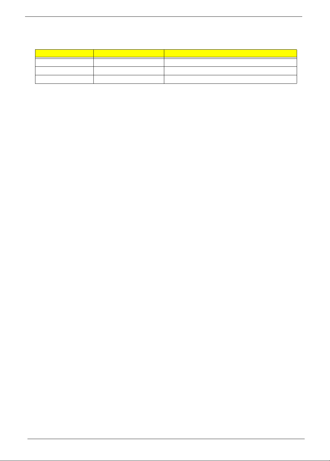
Please refer to the table below for the updates made on Aspire 4720Z/4730ZG/4330 Series service guide.
Date Chapter Updates
II
Page 3

Copyright
Copyright © 2008 by Acer Incorporated. All rights reserved. No part of this publication may be reproduced,
transmitted, transcribed, stored in a retrieval system, or translated into any language or computer language, in
any form or by any means, electronic, mechanical, magnetic, optical, chemical, manual or otherwise, without
the prior written permission of Acer Incorporated.
Disclaimer
The information in this guide is subject to change without notice.
Acer Incorporated makes no representations or warranties, either expressed or implied, with respect to the
contents hereof and specifically disclaims any warranties of merchantability or fitness for any particular
purpose. Any Acer Incorporated software described in this manual is sold or licensed as is. Should the
programs prove defective following their purchase, the buyer (and not Acer Incorporated, its distributor, or its
dealer) assumes the entire cost of all necessary servicing, repair, and any incidental or consequential
damages resulting from any defect in the software.
Acer is a registered trademark of Acer Corporation.
Intel is a registered trademark of Intel Corporation.
Pentium and Pentium II/III are trademarks of Intel Corporation.
Other brand and product names are trademarks and/or registered trademarks of their respective holders.
III
Page 4
Conventions
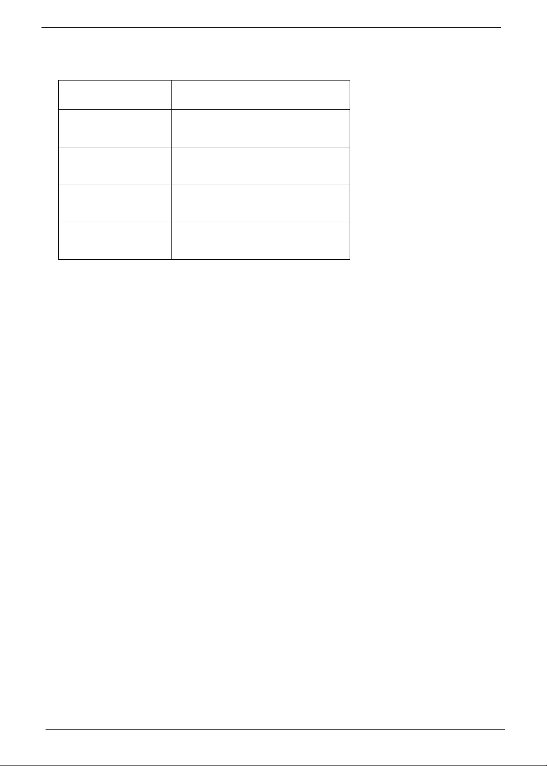
The following conventions are used in this manual:
SCREEN MESSAGES Denotes actual messages that appear
on screen.
NOTE Gives bits and pieces of additional
information related to the current
topic.
WARNING Alerts you to any damage that might
result from doing or not doing specific
actions.
CAUTION Gives precautionary measures to
avoid possible hardware or software
problems.
IMPORTANT Reminds you to do specific actions
relevant to the accomplishment of
procedures.
IV
Page 5

Preface
Before using this information and the product it supports, please read the following general information.
1. This Service Guide provides you with all technical information relating to the BASIC CONFIGURATION
decided for Acer's global product offering. To better fit local market requirements and enhance product
competitiveness, your regional office MAY have decided to extend the functionality of a machine (e.g.
add-on card, modem, or extra memory capability). These LOCALIZED FEATURES will NOT be covered
in this generic service guide. In such cases, please contact your regional offices or the responsible
personnel/channel to provide you with further technical details.
2. Please note WHEN ORDERING FRU PARTS, that you should check the most up-to-date information
available on your regional web or channel. If, for whatever reason, a part number change is made, it will
not be noted in the printed Service Guide. For ACER-AUTHORIZED SERVICE PROVIDERS, your Acer
office may have a DIFFERENT part number code to those given in the FRU list of this printed Service
Guide. You MUST use the list provided by your regional Acer office to order FRU parts for repair and
service of customer machines.
V
Page 6

VI
Page 7
Table of Contents
System Specifications 1
Features . . . . . . . . . . . . . . . . . . . . . . . . . . . . . . . . . . . . . . . . . . . . . . . . . . . . . . . . . . . .1
System Block Diagram . . . . . . . . . . . . . . . . . . . . . . . . . . . . . . . . . . . . . . . . . . . . . . . . .4
Your Acer Notebook tour . . . . . . . . . . . . . . . . . . . . . . . . . . . . . . . . . . . . . . . . . . . . . . .5
Front View . . . . . . . . . . . . . . . . . . . . . . . . . . . . . . . . . . . . . . . . . . . . . . . . . . . . . . .5
Closed Front View . . . . . . . . . . . . . . . . . . . . . . . . . . . . . . . . . . . . . . . . . . . . . . . . .6
Left View . . . . . . . . . . . . . . . . . . . . . . . . . . . . . . . . . . . . . . . . . . . . . . . . . . . . . . . .7
Right View . . . . . . . . . . . . . . . . . . . . . . . . . . . . . . . . . . . . . . . . . . . . . . . . . . . . . . .8
Rear View . . . . . . . . . . . . . . . . . . . . . . . . . . . . . . . . . . . . . . . . . . . . . . . . . . . . . . .8
Bottom View . . . . . . . . . . . . . . . . . . . . . . . . . . . . . . . . . . . . . . . . . . . . . . . . . . . . .9
Indicators . . . . . . . . . . . . . . . . . . . . . . . . . . . . . . . . . . . . . . . . . . . . . . . . . . . . . .10
Easy-Launch Buttons . . . . . . . . . . . . . . . . . . . . . . . . . . . . . . . . . . . . . . . . . . . . .10
Touchpad Basics (with fingerprint reader) . . . . . . . . . . . . . . . . . . . . . . . . . . . . .11
Using the Keyboard . . . . . . . . . . . . . . . . . . . . . . . . . . . . . . . . . . . . . . . . . . . . . . . . . .12
Lock Keys and embedded numeric keypad . . . . . . . . . . . . . . . . . . . . . . . . . . . .12
Windows Keys . . . . . . . . . . . . . . . . . . . . . . . . . . . . . . . . . . . . . . . . . . . . . . . . . .13
Hot Keys . . . . . . . . . . . . . . . . . . . . . . . . . . . . . . . . . . . . . . . . . . . . . . . . . . . . . . .14
Special Key . . . . . . . . . . . . . . . . . . . . . . . . . . . . . . . . . . . . . . . . . . . . . . . . . . . . .15
Using the System Utilities . . . . . . . . . . . . . . . . . . . . . . . . . . . . . . . . . . . . . . . . . . . . . .16
Acer GridVista (dual-display compatible) . . . . . . . . . . . . . . . . . . . . . . . . . . . . . .16
Hardware Specifications and Configurations . . . . . . . . . . . . . . . . . . . . . . . . . . . . . . .18
System Utilities 27
BIOS Setup Utility . . . . . . . . . . . . . . . . . . . . . . . . . . . . . . . . . . . . . . . . . . . . . . . . . . . .27
Navigating the BIOS Utility . . . . . . . . . . . . . . . . . . . . . . . . . . . . . . . . . . . . . . . . .27
Information . . . . . . . . . . . . . . . . . . . . . . . . . . . . . . . . . . . . . . . . . . . . . . . . . . . . .28
Main . . . . . . . . . . . . . . . . . . . . . . . . . . . . . . . . . . . . . . . . . . . . . . . . . . . . . . . . . .29
Security . . . . . . . . . . . . . . . . . . . . . . . . . . . . . . . . . . . . . . . . . . . . . . . . . . . . . . . .30
Boot . . . . . . . . . . . . . . . . . . . . . . . . . . . . . . . . . . . . . . . . . . . . . . . . . . . . . . . . . . .33
Exit . . . . . . . . . . . . . . . . . . . . . . . . . . . . . . . . . . . . . . . . . . . . . . . . . . . . . . . . . . .34
BIOS Flash Utility . . . . . . . . . . . . . . . . . . . . . . . . . . . . . . . . . . . . . . . . . . . . . . . . . . . .35
Remove HDD/BIOS Utility . . . . . . . . . . . . . . . . . . . . . . . . . . . . . . . . . . . . . . . . . . . . .37
Removing BIOS Passwords: . . . . . . . . . . . . . . . . . . . . . . . . . . . . . . . . . . . . . . . .39
Machine Disassembly and Replacement 41
Disassembly Requirements . . . . . . . . . . . . . . . . . . . . . . . . . . . . . . . . . . . . . . . . . . . .41
General Information . . . . . . . . . . . . . . . . . . . . . . . . . . . . . . . . . . . . . . . . . . . . . . . . . .42
Pre-disassembly Instructions . . . . . . . . . . . . . . . . . . . . . . . . . . . . . . . . . . . . . . .42
Disassembly Process . . . . . . . . . . . . . . . . . . . . . . . . . . . . . . . . . . . . . . . . . . . . .42
External Module Disassembly Process . . . . . . . . . . . . . . . . . . . . . . . . . . . . . . . . . . .43
External Modules Disassembly Flowchart . . . . . . . . . . . . . . . . . . . . . . . . . . . . .43
Removing the Battery Pack . . . . . . . . . . . . . . . . . . . . . . . . . . . . . . . . . . . . . . . .44
Removing the SD dummy card . . . . . . . . . . . . . . . . . . . . . . . . . . . . . . . . . . . . . .45
Removing the ExpressCard dummy card . . . . . . . . . . . . . . . . . . . . . . . . . . . . . .46
Removing the Lower Covers . . . . . . . . . . . . . . . . . . . . . . . . . . . . . . . . . . . . . . . .47
Removing the DIMM Modules . . . . . . . . . . . . . . . . . . . . . . . . . . . . . . . . . . . . . . .49
Removing the WLAN Module . . . . . . . . . . . . . . . . . . . . . . . . . . . . . . . . . . . . . . .50
Removing the Hard Disk Drive Module . . . . . . . . . . . . . . . . . . . . . . . . . . . . . . . .52
Removing the Optical Drive Module . . . . . . . . . . . . . . . . . . . . . . . . . . . . . . . . . .55
Main Unit Disassembly Process . . . . . . . . . . . . . . . . . . . . . . . . . . . . . . . . . . . . . . . . .58
Main Unit Disassembly Flowchart . . . . . . . . . . . . . . . . . . . . . . . . . . . . . . . . . . . .58
Removing the Switch Cover . . . . . . . . . . . . . . . . . . . . . . . . . . . . . . . . . . . . . . . .59
Removing the Keyboard . . . . . . . . . . . . . . . . . . . . . . . . . . . . . . . . . . . . . . . . . . .61
Removing the Antenna . . . . . . . . . . . . . . . . . . . . . . . . . . . . . . . . . . . . . . . . . . . .63
VII
Page 8
Table of Contents
Removing the LCD Module . . . . . . . . . . . . . . . . . . . . . . . . . . . . . . . . . . . . . . . . .66
Removing the Upper Cover . . . . . . . . . . . . . . . . . . . . . . . . . . . . . . . . . . . . . . . .68
Removing the Touch Pad Bracket . . . . . . . . . . . . . . . . . . . . . . . . . . . . . . . . . . .72
Removing the Finger Print Reader . . . . . . . . . . . . . . . . . . . . . . . . . . . . . . . . . . .74
Removing the Launch Board . . . . . . . . . . . . . . . . . . . . . . . . . . . . . . . . . . . . . . .75
Removing the Speaker Module . . . . . . . . . . . . . . . . . . . . . . . . . . . . . . . . . . . . . .76
Removing the Switch Board . . . . . . . . . . . . . . . . . . . . . . . . . . . . . . . . . . . . . . . .78
Removing the Touch Pad Board . . . . . . . . . . . . . . . . . . . . . . . . . . . . . . . . . . . . .79
Removing the I/O Board . . . . . . . . . . . . . . . . . . . . . . . . . . . . . . . . . . . . . . . . . . .80
Removing the Bluetooth module . . . . . . . . . . . . . . . . . . . . . . . . . . . . . . . . . . . . .82
Removing the Modem Module . . . . . . . . . . . . . . . . . . . . . . . . . . . . . . . . . . . . . .84
Removing the Main Board . . . . . . . . . . . . . . . . . . . . . . . . . . . . . . . . . . . . . . . . .86
Removing the Thermal Module . . . . . . . . . . . . . . . . . . . . . . . . . . . . . . . . . . . . . .89
Removing the CPU . . . . . . . . . . . . . . . . . . . . . . . . . . . . . . . . . . . . . . . . . . . . . . .90
Removing the CPU Fan . . . . . . . . . . . . . . . . . . . . . . . . . . . . . . . . . . . . . . . . . . .91
Removing the HDMI Module . . . . . . . . . . . . . . . . . . . . . . . . . . . . . . . . . . . . . . . .93
LCD Module Disassembly Process . . . . . . . . . . . . . . . . . . . . . . . . . . . . . . . . . . . . . .94
LCD Module Disassembly Flowchart . . . . . . . . . . . . . . . . . . . . . . . . . . . . . . . . .94
Removing the LCD Bezel . . . . . . . . . . . . . . . . . . . . . . . . . . . . . . . . . . . . . . . . . .95
Removing the Inverter Board . . . . . . . . . . . . . . . . . . . . . . . . . . . . . . . . . . . . . . .97
Removing the Camera Module . . . . . . . . . . . . . . . . . . . . . . . . . . . . . . . . . . . . . .99
Removing the LCD Panel . . . . . . . . . . . . . . . . . . . . . . . . . . . . . . . . . . . . . . . . .101
Removing the LCD Brackets and FPC Cable . . . . . . . . . . . . . . . . . . . . . . . . . .102
Removing the Antennas . . . . . . . . . . . . . . . . . . . . . . . . . . . . . . . . . . . . . . . . . .104
Removing the MIC Module . . . . . . . . . . . . . . . . . . . . . . . . . . . . . . . . . . . . . . . .105
LCD Module Reassembly Procedure . . . . . . . . . . . . . . . . . . . . . . . . . . . . . . . . . . . .106
Replacing the LCD Panel . . . . . . . . . . . . . . . . . . . . . . . . . . . . . . . . . . . . . . . . .106
Replacing the LCD Bezel . . . . . . . . . . . . . . . . . . . . . . . . . . . . . . . . . . . . . . . . .109
Main Module Reassembly Procedure . . . . . . . . . . . . . . . . . . . . . . . . . . . . . . . . . . . .110
Replacing the CPU . . . . . . . . . . . . . . . . . . . . . . . . . . . . . . . . . . . . . . . . . . . . . .110
Replacing the Thermal Module . . . . . . . . . . . . . . . . . . . . . . . . . . . . . . . . . . . . .110
Replacing the CPU Fan Module . . . . . . . . . . . . . . . . . . . . . . . . . . . . . . . . . . . .111
Replacing the HDMI Module . . . . . . . . . . . . . . . . . . . . . . . . . . . . . . . . . . . . . . .111
Replacing the Mainboard . . . . . . . . . . . . . . . . . . . . . . . . . . . . . . . . . . . . . . . . .112
Replacing the I/O Board . . . . . . . . . . . . . . . . . . . . . . . . . . . . . . . . . . . . . . . . . .114
Replacing the Bluetooth Board . . . . . . . . . . . . . . . . . . . . . . . . . . . . . . . . . . . . .114
Replacing the Modem Module . . . . . . . . . . . . . . . . . . . . . . . . . . . . . . . . . . . . .115
Replacing the Finger Print Reader . . . . . . . . . . . . . . . . . . . . . . . . . . . . . . . . . .116
Replacing the Touch Pad Bracket . . . . . . . . . . . . . . . . . . . . . . . . . . . . . . . . . .117
Replacing the Launch Board . . . . . . . . . . . . . . . . . . . . . . . . . . . . . . . . . . . . . . .118
Replacing the Switch Board . . . . . . . . . . . . . . . . . . . . . . . . . . . . . . . . . . . . . . .118
Replacing the Antenna Cables . . . . . . . . . . . . . . . . . . . . . . . . . . . . . . . . . . . . .119
Replacing the Speaker Module . . . . . . . . . . . . . . . . . . . . . . . . . . . . . . . . . . . . .120
Replacing the Keyboard . . . . . . . . . . . . . . . . . . . . . . . . . . . . . . . . . . . . . . . . . .120
Replacing the Switch Cover . . . . . . . . . . . . . . . . . . . . . . . . . . . . . . . . . . . . . . .122
Replacing the WLAN Module . . . . . . . . . . . . . . . . . . . . . . . . . . . . . . . . . . . . . .122
Replacing the Hard Disk Drive Module . . . . . . . . . . . . . . . . . . . . . . . . . . . . . . .123
Replacing the DIMM Modules . . . . . . . . . . . . . . . . . . . . . . . . . . . . . . . . . . . . . .124
Replacing the ODD Module . . . . . . . . . . . . . . . . . . . . . . . . . . . . . . . . . . . . . . .125
Replacing the Lower Covers . . . . . . . . . . . . . . . . . . . . . . . . . . . . . . . . . . . . . . .126
Replacing the Express and SD Card Trays . . . . . . . . . . . . . . . . . . . . . . . . . . .127
Troubleshooting 129
Common Problems . . . . . . . . . . . . . . . . . . . . . . . . . . . . . . . . . . . . . . . . . . . . . . . . . .129
Power On Issue . . . . . . . . . . . . . . . . . . . . . . . . . . . . . . . . . . . . . . . . . . . . . . . .130
VIII
Page 9
Table of Contents
No Display Issue . . . . . . . . . . . . . . . . . . . . . . . . . . . . . . . . . . . . . . . . . . . . . . . .131
Random Loss of BIOS Settings . . . . . . . . . . . . . . . . . . . . . . . . . . . . . . . . . . . .132
LCD Failure . . . . . . . . . . . . . . . . . . . . . . . . . . . . . . . . . . . . . . . . . . . . . . . . . . . .133
Built-In Keyboard Failure . . . . . . . . . . . . . . . . . . . . . . . . . . . . . . . . . . . . . . . . .133
Touchpad Failure . . . . . . . . . . . . . . . . . . . . . . . . . . . . . . . . . . . . . . . . . . . . . . .134
Internal Speaker Failure . . . . . . . . . . . . . . . . . . . . . . . . . . . . . . . . . . . . . . . . . .134
Internal Microphone Failure . . . . . . . . . . . . . . . . . . . . . . . . . . . . . . . . . . . . . . .136
HDD Not Operating Correctly . . . . . . . . . . . . . . . . . . . . . . . . . . . . . . . . . . . . . .137
ODD Failure . . . . . . . . . . . . . . . . . . . . . . . . . . . . . . . . . . . . . . . . . . . . . . . . . . .138
Modem Function Failure . . . . . . . . . . . . . . . . . . . . . . . . . . . . . . . . . . . . . . . . . .141
Wireless Function Failure . . . . . . . . . . . . . . . . . . . . . . . . . . . . . . . . . . . . . . . . .141
EasyTouch Button Failure . . . . . . . . . . . . . . . . . . . . . . . . . . . . . . . . . . . . . . . . .142
Thermal Unit Failure . . . . . . . . . . . . . . . . . . . . . . . . . . . . . . . . . . . . . . . . . . . . .142
External Mouse Failure . . . . . . . . . . . . . . . . . . . . . . . . . . . . . . . . . . . . . . . . . . .143
Other Failures . . . . . . . . . . . . . . . . . . . . . . . . . . . . . . . . . . . . . . . . . . . . . . . . . .143
Intermittent Problems . . . . . . . . . . . . . . . . . . . . . . . . . . . . . . . . . . . . . . . . . . . . . . . .144
Undetermined Problems . . . . . . . . . . . . . . . . . . . . . . . . . . . . . . . . . . . . . . . . . . . . . .144
POST Codes Tables . . . . . . . . . . . . . . . . . . . . . . . . . . . . . . . . . . . . . . . . . . . . . . . . .145
Sec . . . . . . . . . . . . . . . . . . . . . . . . . . . . . . . . . . . . . . . . . . . . . . . . . . . . . . . . . .145
Memory: . . . . . . . . . . . . . . . . . . . . . . . . . . . . . . . . . . . . . . . . . . . . . . . . . . . . . .145
BDS & Specific action: . . . . . . . . . . . . . . . . . . . . . . . . . . . . . . . . . . . . . . . . . . .146
Each PEIM entry point used in 80_PORT . . . . . . . . . . . . . . . . . . . . . . . . . . . . .147
Each Driver entry point used in 80_PORT . . . . . . . . . . . . . . . . . . . . . . . . . . . .147
Each SmmDriver entry point used in 80_PORT . . . . . . . . . . . . . . . . . . . . . . . .150
Jumper and Connector Locations 151
Top View . . . . . . . . . . . . . . . . . . . . . . . . . . . . . . . . . . . . . . . . . . . . . . . . . . . . . . . . . .151
Bottom View . . . . . . . . . . . . . . . . . . . . . . . . . . . . . . . . . . . . . . . . . . . . . . . . . . . . . . .152
Clearing Password Check and BIOS Recovery . . . . . . . . . . . . . . . . . . . . . . . . . . . .153
Clearing Password Check . . . . . . . . . . . . . . . . . . . . . . . . . . . . . . . . . . . . . . . . .153
BIOS Recovery by Crisis Disk . . . . . . . . . . . . . . . . . . . . . . . . . . . . . . . . . . . . .154
FRU (Field Replaceable Unit) List 155
Aspire 4730Z/4730ZG/4330 Exploded Diagrams ......... . . . . . . . . . . . . . . . . . . . . . .156
Main Module . . . . . . . . . . . . . . . . . . . . . . . . . . . . . . . . . . . . . . . . . . . . . . . . . . .156
LCD Module . . . . . . . . . . . . . . . . . . . . . . . . . . . . . . . . . . . . . . . . . . . . . . . . . . .157
Aspire 4730Z/4730ZG/4330 FRU List . ......... . . . . . . . . . . . . . . . . . . . . . . . . . . . . . .158
Screw List . . . . . . . . . . . . . . . . . . . . . . . . . . . . . . . . . . . . . . . . . . . . . . . . . . . . .165
Model Definition and Configuration 166
Aspire 4730Z/4730ZG/4330 Series . . . . . . . . . . . . . . . . . . . . . . . . . . . . . . . . . . . .166
Test Compatible Components 177
Microsoft® Windows® Vista Environment Test . . . . . . . . . . . . . . . . . . . . . . . . . . . .178
Online Support Information 185
Index 187
IX
Page 10
Table of Contents
X
Page 11

System Specifications
Features
Below is a brief summary of the computer’s many feature:
NOTE: Items marked with * denote only selected models.
Operating System
• Genuine Windows Vista™
Platform
• Intel® Pentium® Dual-Core mobile processor*
• Intel® Celeron® Dual-Core processor*
• Intel® Celeron® processor*
• Mobile Intel® PM45 Express Chipset*
• Mobile Intel® GL40 Express Chipset*
• Acer InviLink™ Nplify™ 802.11b/g/Draft-N*
• Acer InviLink™ 802.11b/g*
Chapter 1
System Memory
• Dual-Channel DDR2 SDRAM support
• Up to 2 GB of DDR2 667 MHz memory, upgradeable to 4 GB using two soDIMM modules*
Display and graphics
• 14.1" WXGA 1280 x 800
• Mobile Intel® GL40 Express Chipset*
• ATI Mobility Radeon™ HD 3470*
Storage subsystem
• 2.5" hard disk drive
• Optical drive options:
• DVD-Super Multi double-layer drive*
• DVD/CD-RW combo drive*
• 5-in-1 card reader
Audio
• Two built-in stereo speakers
• High-definition audio support
• MS-Sound compatible
• Built-in microphone
Chapter 1 1
Page 12

Communication
• Acer Video Conference, featuring:
• Integrated Acer Crystal Eye webcam
• Optional Acer Xpress VoIP phone
• WLAN:
• Acer InviLink™ Nplify™ 802.11b/g/Draft-N*
• Acer InviLink™ 802.11b/g*
• WPAN: Bluetooth® 2.0+EDR
• LAN: Gigabit Ethernet, Wake-on-LAN ready
• Modem: 56K ITU V.92
Privacy control
• BIOS user, supervisor, HDD passwords
• Kensington lock slot
Dimensions and Weight
• 340.4 (W) x 247 (D) x 22.9/42.3 (H) mm (13.4 x 9.7 x 0.9/1.6 inches)
• 2.4 kg (5.29 Ibs)
Power subsystem
• ACPI 3.0
• 48.8 W 4400 mAh
• 3-pin 65 W AC adapter*
• 3-pin 90 W AC adapter*
• Energy Star 4.0
Special keys and controls
• 88-/89-/93-key keyboard
• Touchpad pointing device
• Empowering Key
• Easy-launch buttons: WLAN, volume up and down and Bluetooth®
I/O interface
• ExpressCard™/54 slot
• 5-in-1 card reader (SD™, MMC, MS, MS PRO, xD)
• Two USB 2.0 ports
• External display (VGA) port
• Headphone/speaker/line-out jack
• Microphone-in jack
• Line-in jack
• Ethernet (RJ-45) port
2 Chapter 1
Page 13

• • Modem (RJ-11) port
• • DC-in jack for AC adapter
Environment
• Temperature:
• Operating: 5 °C to 35 °C
• Non-operating: -20 °C to 65 °C
• Humidity (non-condensing):
• Operating: 20% to 80%
• Non-operating: 20% to 80%
NOTE: Items marked with * denote only selected models. The specifications listed above are for reference
only. The exact configuration of your PC depends on the model purchased.
Chapter 1 3
Page 14
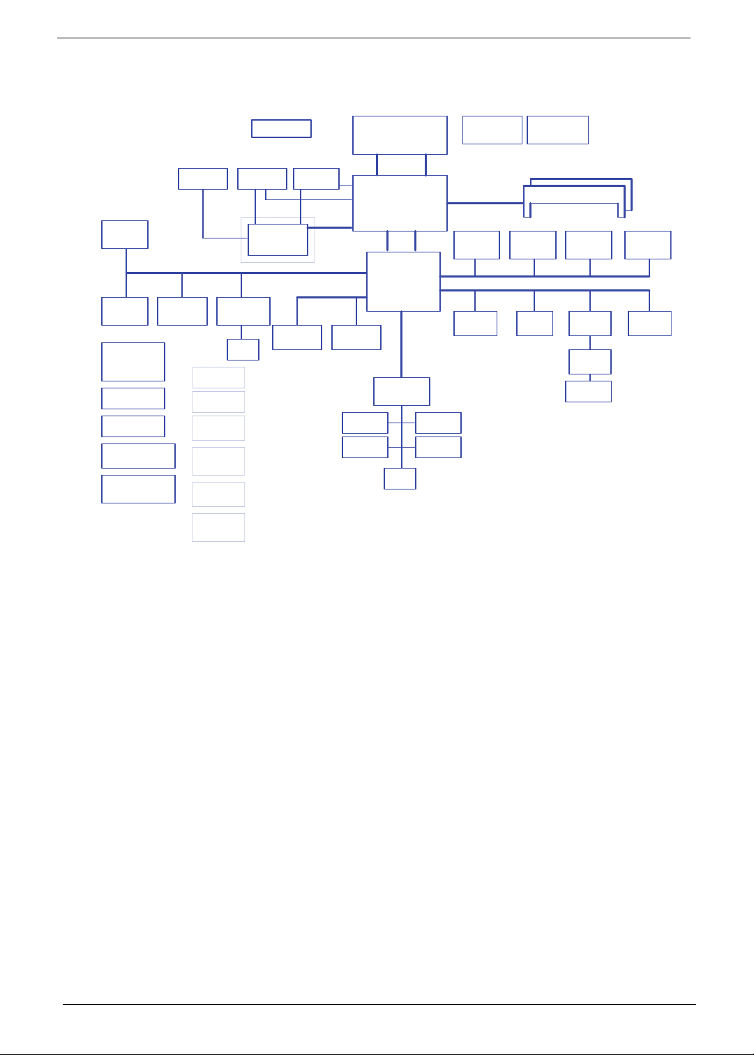
System Block Diagram
Card Reader
JMB385
Socket
DOCKING
(DVI/L AN/
CRT/USB/AUDIO)
MINI Card x2New Card
WLAN, Robson2
RTC CKT.
Power On/Off CKT.
DC/DC Interface CKT.
Power Circuit DC/DC
HDMI Conn.
TMDS
LS-4208P
Media/B Conn.
LS-4202P
BTN/B Conn.
LS-4204P
PWR/B Conn.
LS-4205P
USB/B Conn.
USB port 4
LS-4206P
UMA HDMI/B
LS-4205P
COVER LIGHT
Conn
LCD Conn.
MXM II VGA/B
LAN(GbE)
Realtek RTL8111C
RJ45
Fan Control
LVDS
port 0 port 1
SATA HDD
Conn.
CRT Conn.
LVDS
PCI-Express
16X
PCI-Exp ress
Intel Penryn Processor
uPGA-478 Package
(Socket P)
FSB
667/800/1066MHz
Intel Cantiga
uFCBGA-1329
DMI
Intel ICH9-M
S-ATA
CDROM
Conn.
Touch Pad
EC I/O Buffer
BGA-676
LPC BUS
ENE KB926
CIR
H_D#(0 ..63)H_A#( 3..35)
C-Link
Int.KBD
BIOS
Thermal Sensor
EMC1402-1-ACZL
Memory BUS(DDRII)
Dual Channel
1.8V DDRII 533/667
USB conn x2
USB port 0, 2
3.3V 48M Hz
USB
3.3V 24.576M Hz/48M hz
GMCH HDA
Clock G enerator
ICS9LPRS387
200pin DDRII-SO-DIMM X2
BANK 0, 1, 2, 3
HD Audio
CMOS
Camera
HDA Codec
ALC888S-VC
Bluetooth
Conn
MDC 1.5
Conn
Audio AMP
Phone Jack x3
LS-4201P
Finger Print
AES1610
MXM HDA
4 Chapter 1
Page 15
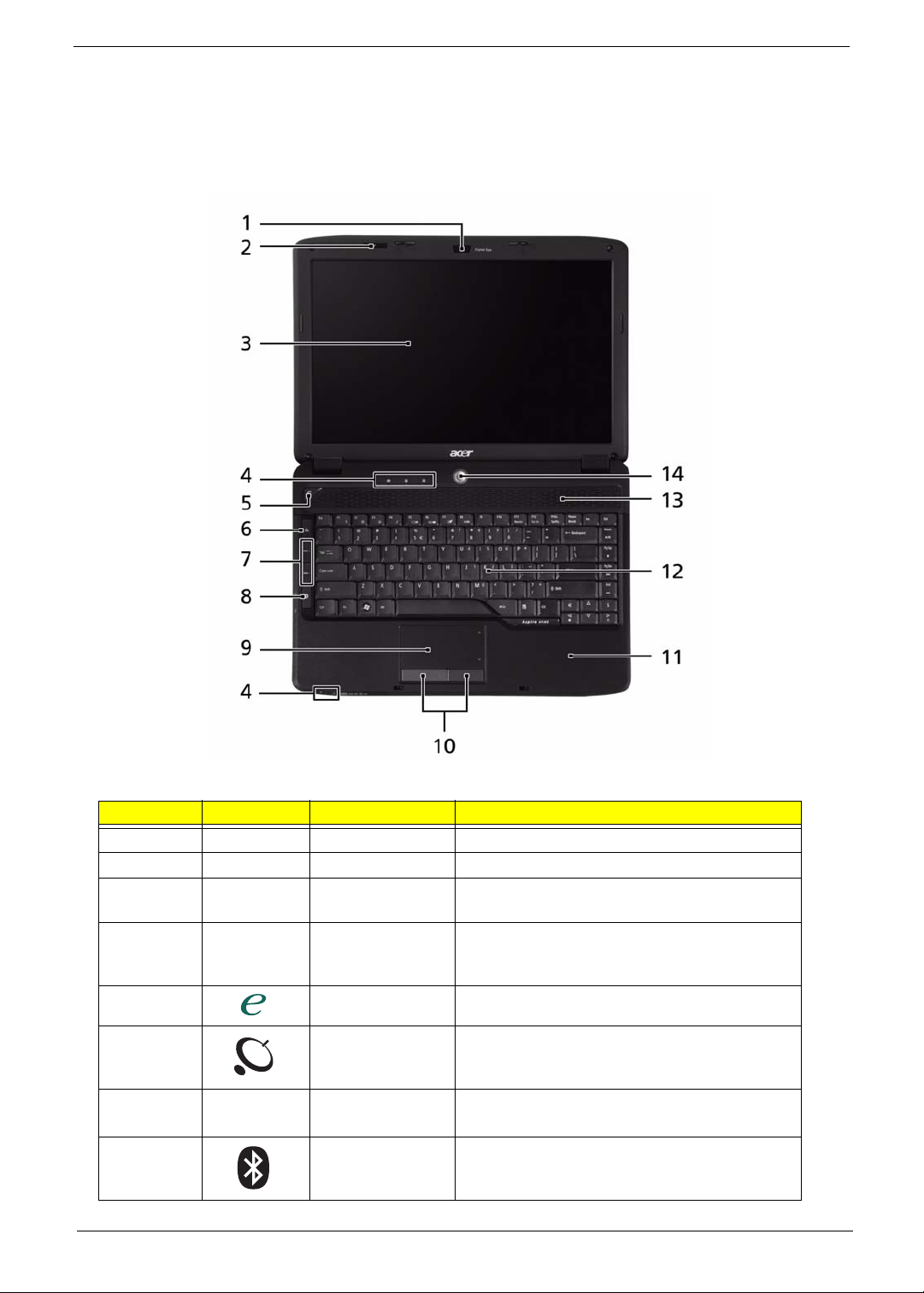
Your Acer Notebook tour
After knowing your computer features, let us show you around your new computer.
Front View
No. Icon Item Description
1 Acer Crystal Eye Web camera for video communication.
2 Microphone Internal microphone for sound recording.
3 Display screen Also called Liquid-Crystal Display (LCD),
displays computer output.
4 Status indicators Light-Emitting Diodes (LEDs) that light up to
show the status of the computer's functions
and components.
5 Empowering key Launch Acer Empowering Technology.
6 Wireless
communication
button
7VOL+
VOL-
8 Bluetooth
Chapter 1 5
Volume Up/
Volume Down
communication
button
Enables/disables the wireless function.
Increase system volume/decrease system
volume.
Enables/disables the 3G/Bluetooth function.
Page 16
No. Icon Item Description
9 T ouchpad T ouch-sensitive pointing device which functions
like a computer mouse.
10 Click buttons
(left and right)
1 1 Palmrest Comfortable support area for your hands when
12 Keyboard For entering data into your computer.
13 Speakers Left and right speakers deliver stereo audio
14 Power button Turns the computer on and off.
The left and right buttons function like the left
and right mouse buttons.
you use the computer.
output.
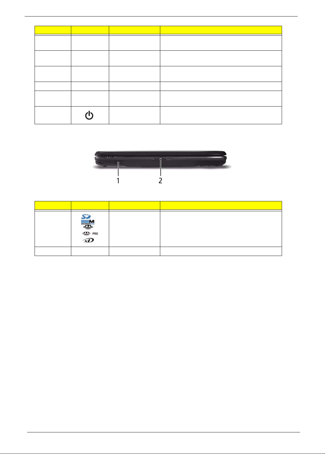
Closed Front View
No. Icon Item Description
1 5-in-1 card
reader
2 Latch Locks and releases the lid.
Accepts Secure Digital (SD), MultiMediaCard
(MMC), Memory Stick (MS), Memory Stick
PRO (MS PRO), xD-Picture Card (xD).
Note: Push to remove/install the card. Only
one card can operate at any given time.
6 Chapter 1
Page 17
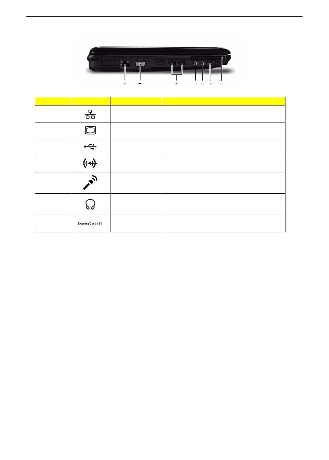
Left View
No. Icon Item Description
1 Ethernet (RJ-45)
port
2 External display
(VGA) port
3 2 USB 2.0 ports Connect to USB 2.0 devices (e.g. USB mouse,
4 Line-in jack Accepts audio line-in devices (e.g., audio CD
5 Microphone jack Accepts inputs from external microphones.
Connects to an Ethernet 10/100/1000-based
network.
Connects to a display device
(e.g. external monitor, LCD projector).
USB camera).
player, stereo walkman, mp3 player).
6 Headphones/
speaker/line-out
jack
7 ExpressCard/54
slot
Connects to audio line-out devices (e.g.,
speakers, headphones).
Accepts one ExpressCard/54 module.
Chapter 1 7
Page 18
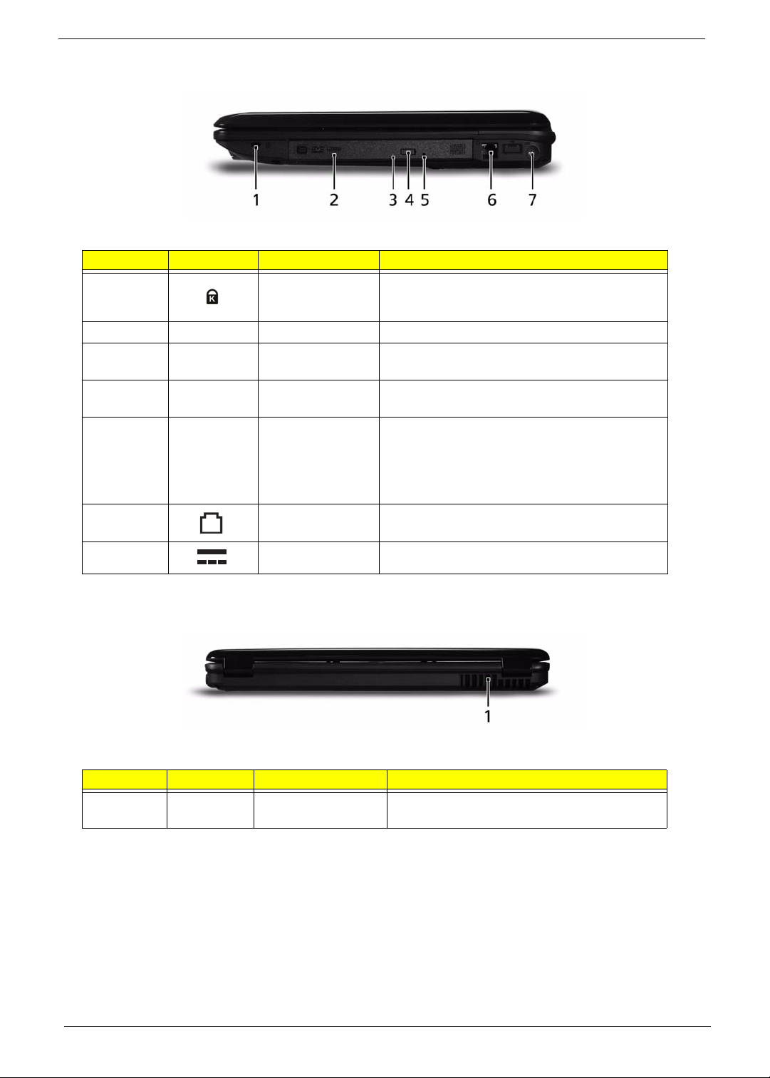
Right View
No. Icon Item Description
1 Kensington lock
slot
2 Optical drive Internal optical drive; accepts CDs or DVDs.
3 Optical disk access
indicator
4 Optical drive eject
button
5 Emergency eject
hole
6 Modem (RJ-11)
port
7 DC-in jack Connects to an AC adapter
Connects to a Kensington-compatible computer
security lock.
Lights up when the optical drive is active.
Ejects the optical disk from the drive.
Ejects the optical drive tray when the computer is
turned off.
Note: Insert a paper clip into the emergency eject
hole to eject the optical drive tray when the
computer is off.
Connects to a phone line.
Rear View
No. Icon Item Description
1 Ventilation slots Enable the computer to stay cool, even after
prolonged use.
8 Chapter 1
Page 19
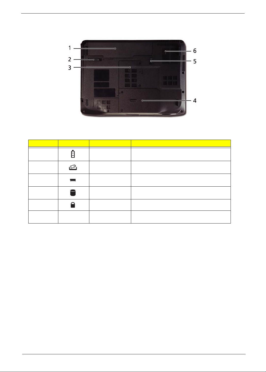
Bottom View
No. Icon Item Description
1 Battery bay Houses the computer's battery pack.
2 Battery release
latch
3 Memory
compartment
4 Hard disk bay Houses the computer's hard disk (secured with
5 Battery lock Locks the battery in position.
6 Ventilation slots
and cooling fan
Releases the battery for removal.
Houses the computer's main memory.
screws).
Enable the computer to stay cool, even after
prolonged use.
Chapter 1 9
Page 20
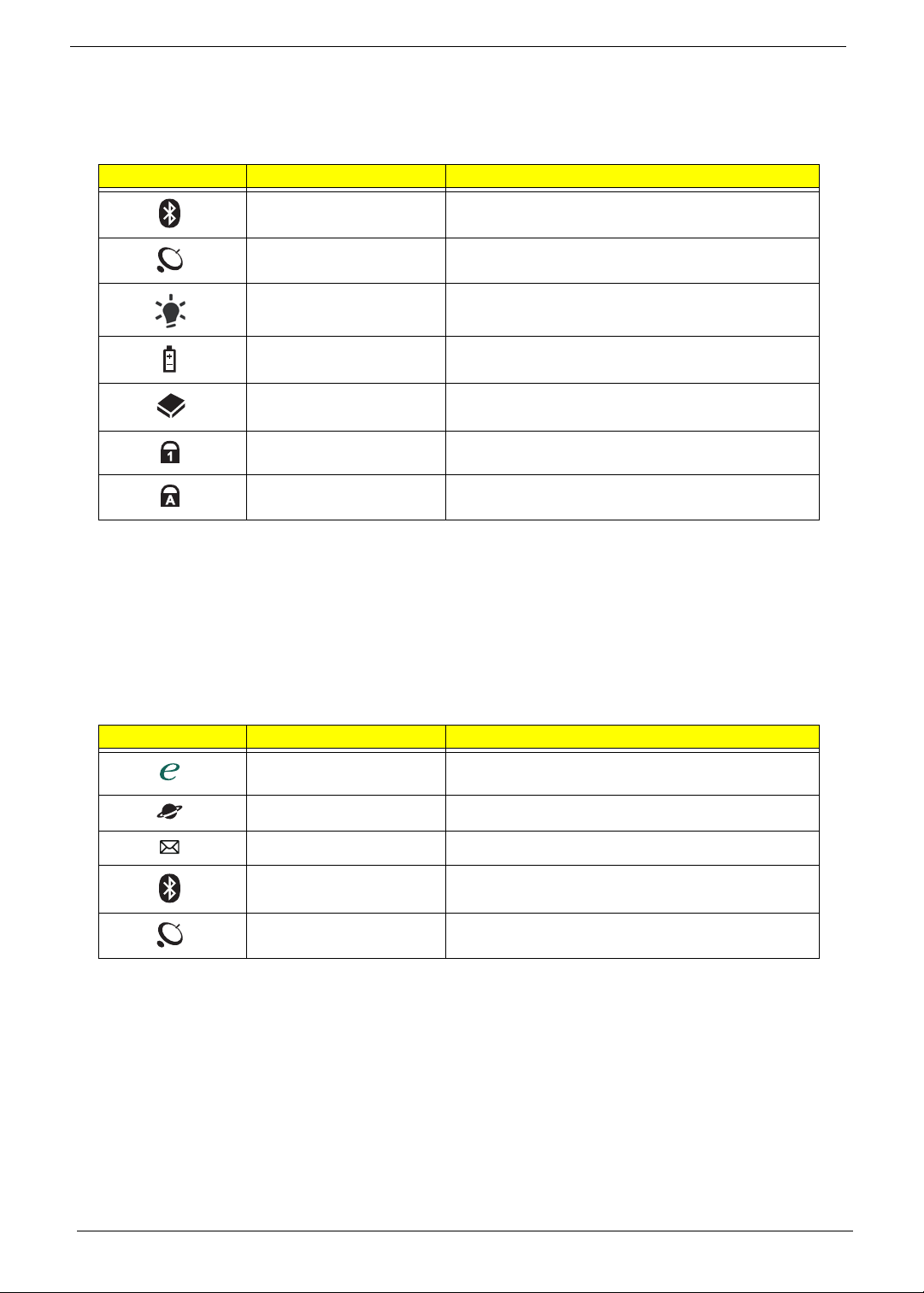
Indicators
The computer has several easy-to-read status indicators:
The front panel indicators are visible even when the computer cover is closed.
Icon Function Description
Bluetooth Indicates the status of Bluetooth communication.
WLAN Indicates the status of wireless LAN
communication.
Power Indicates the computer's power status.
Battery Indicates the computer's battery status.
HDD Indicates when the hard disk drive is active.
Num Lock Lights up when Num Lock is activated.
Caps Lock Lights up when Caps Lock is activated.
NOTE: 1. Charging: The battery light show s amber when the battery is charging. 2. Fully charged: The light
shows green when in AC mode.
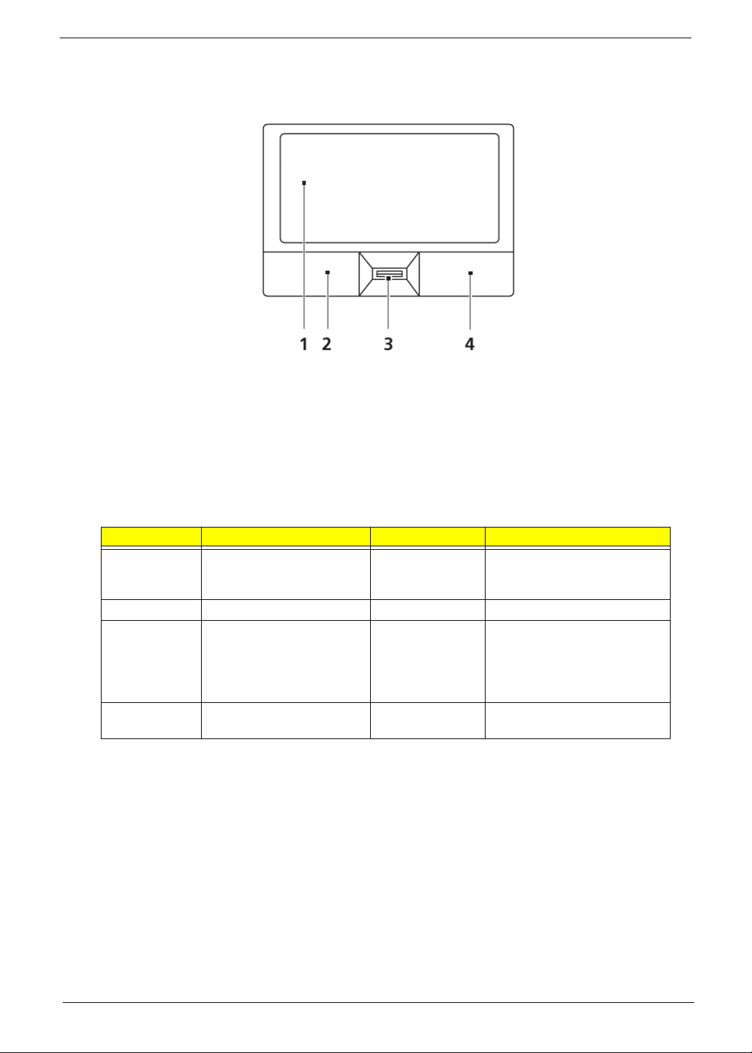
Easy-Launch Buttons
Located beside the keyboard are application buttons. These buttons are called easy-launch buttons. They are:
WLAN, Internet, email, Bluetooth, Arcade and Acer Empowering Technology.
The mail and Web browser buttons are pre-set to email and Internet programs, but can be reset by users. To
set the Web browser, mail and programmable buttons, run the Acer Launch Manager.
Icon Function Description
Empowering Technology Launch Acer Empowering Technology.
(user-programmable)
Web browser Internet browser (user-Programmable)
Mail Email application (user-Programmable)
Bluetooth communication
switch
Wireless communication
switch
Enables/disables the Bluetooth function.
Enables/disables the wireless function.
10 Chapter 1
Page 21
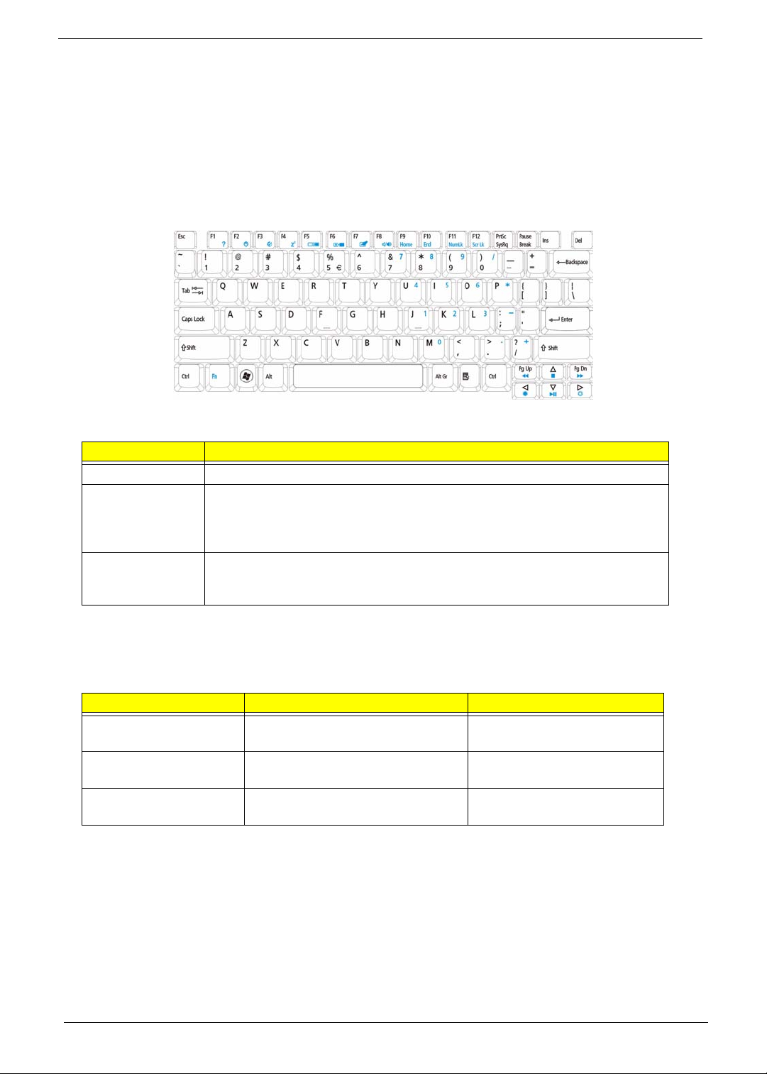
Touchpad Basics (with fingerprint reader)
The following items show you how to use the touchpad with Acer Bio-Protection fingerprint reader:
• Move your finger across the touchpad (2) to move the cursor.
• Press the left (1) and right (4) buttons located beneath the touchpad to perform selection and
execution functions. These two buttons are similar to the left and right buttons on a mouse.
Tapping on the touchpad is the same as clicking the left button.
• Use Acer Bio-Protection fingerprint reader (3) supporting Acer FingerNav 4-way control function
(only for certain models) or the 4-way scroll (3) button (only for certain models) to scroll up or down
and move left or right a page. This fingerprint reader or button mimics your cursor pressing on the
right scroll bar of Windows applications.
Function Left Button (1) Right Button (3) Main touchpad (2)
Execute Quickly click twice. Tap twice (at the same speed
as double-clicking a mouse
button).
Select Click once. Tap once.
Drag Click and hold, then use
finger on the touchpad to
drag the cursor.
Tap twice (at the same speed
as double-clicking a mouse
button); rest your finger on
the touchpad on the second
tap and drag the cursor.
Access
Click once.
context menu
NOTE: When using the touchpad, keep it - and your fingers - dry and clean. The touchpad is sensitive to finger
movement; hence, the lighter the touch, the better the response. Tapping too hard will not increase the
touchpad’s responsiveness.
Chapter 1 11
Page 22
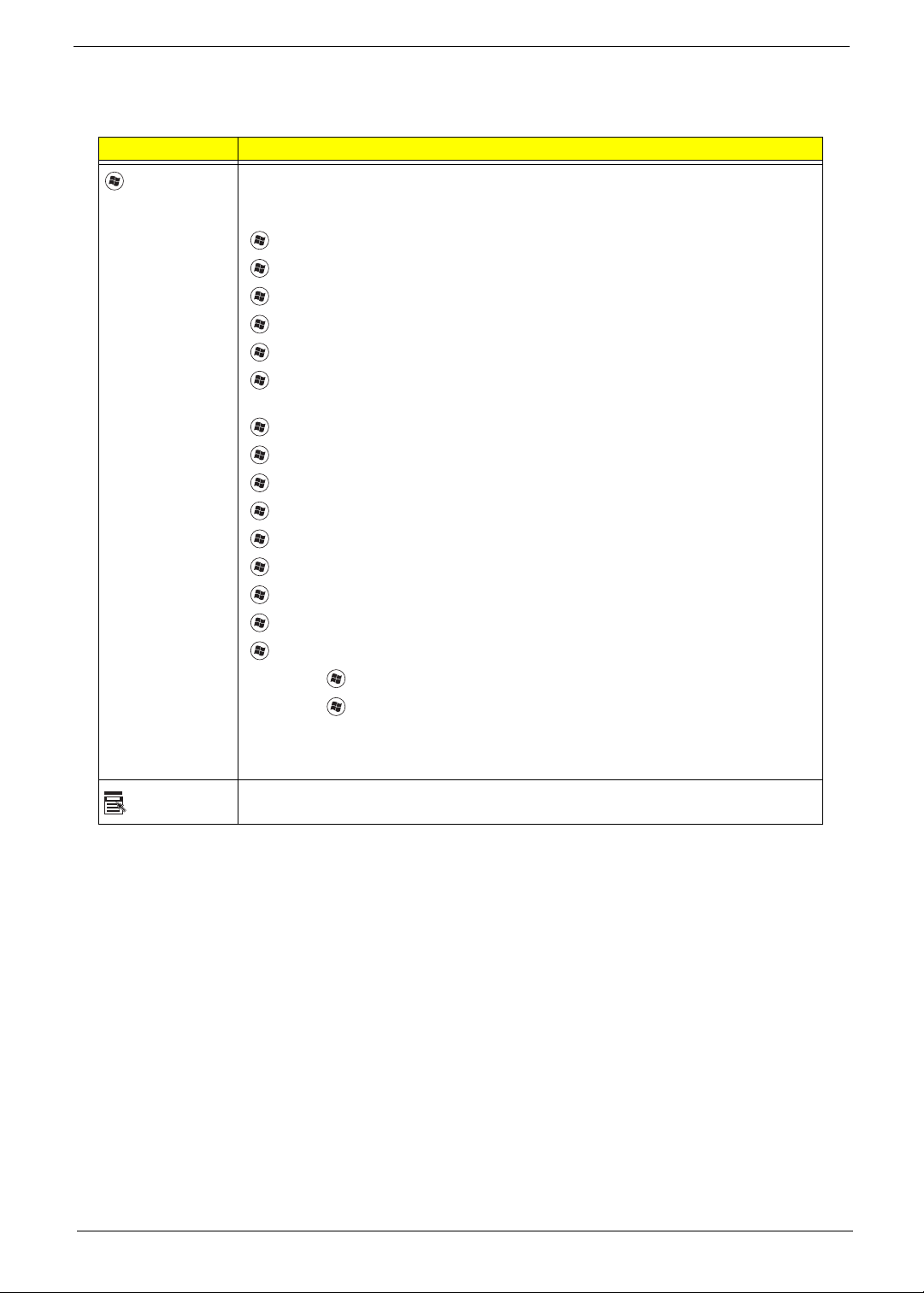
Using the Keyboard
The keyboard has full-sized keys and an embedded numeric keypad, separate cursor, lock, Windows, function
and special keys.
Lock Keys and embedded numeric keypad
The keyboard has three lock keys which you can toggle on and off.
Lock key Description
Caps Lock When Caps Lock is on, all alphabetic characters typed are in uppercase.
Num Lock
<Fn> + <F11>
Scroll Lock <Fn> +
<F12>
When Num Lock is on, the embedded keypad is in numeric mode. The keys
function as a calculator (complete with the arithmetic operators +, -, *, and /). Use
this mode when you need to do a lot of numeric data entry. A better solution
would be to connect an external keypad.
When Scroll Lock is on, the screen moves one line up or down when you press
the up or down arrow keys respectively. Scroll Lock does not work with some
applications.
The embedded numeric keypad functions like a desktop numeric keypad. It is indicated by small characters
located on the upper right corner of the keycaps. To simplify the keyboard legend, cursor-control key symbols
are not printed on the keys.
Desired access Num Lock on Num Lock off
Number keys on
embedded keypad
Cursor-control keys on
embedded keypad
Main keyboard keys Hold <Fn> while typing letters on
Type numbers in a normal manner.
Hold <Shift> while using cursorcontrol keys.
embedded keypad.
Hold <Fn> while using cursorcontrol keys.
Type the letters in a normal
manner.
12 Chapter 1
Page 23
Windows Keys
The keyboard has two keys that perform Windows-specific functions.
Key Description
Windows key Pressed alone, this key has the same effect as clicking on the Windows Start button;
it launches the Start menu. It can also be used with other keys to provide a variety of
functions:
<>: Open or close the Start menu
<> + <D>: Display the desktop
<> + <E>: Open Windows Explore
<> + <F>: Search for a file or folder
<> + <G>: Cycle through Sidebar gadgets
<> + <L>: Lock your computer (if you are connected to a network domain), or
switch users (if you're not connected to a network domain)
<> + <M>: Minimizes all windows
<> + <R>: Open the Run dialog box
<> + <T>: Cycle through programs on the taskbar
<> + <U>: Open Ease of Access Center
<> + <X>: Open Windows Mobility Center
<> + <BREAK>: Display the System Properties dialog box
<> + <SHIFT+M>: Restore minimized windows to the desktop
<> + <TAB>: Cycle through programs on the taskbar by using Windows Flip 3-D
<> + <SPACEBAR>: Bring all gadgets to the front and select Windows Sidebar
Application
key
<CTRL> +
<CTRL> + <> + <TAB>: Use the arrow keys to cycle through programs on the
Note: Depending on your edition of Windows Vista, some shortcuts may not function
This key has the same effect as clicking the right mouse button; it opens the
application's context menu.
<> + <F>: Search for computers (if you are on a network)
taskbar by using Windows Flip 3-D
as described.
Chapter 1 13
Page 24
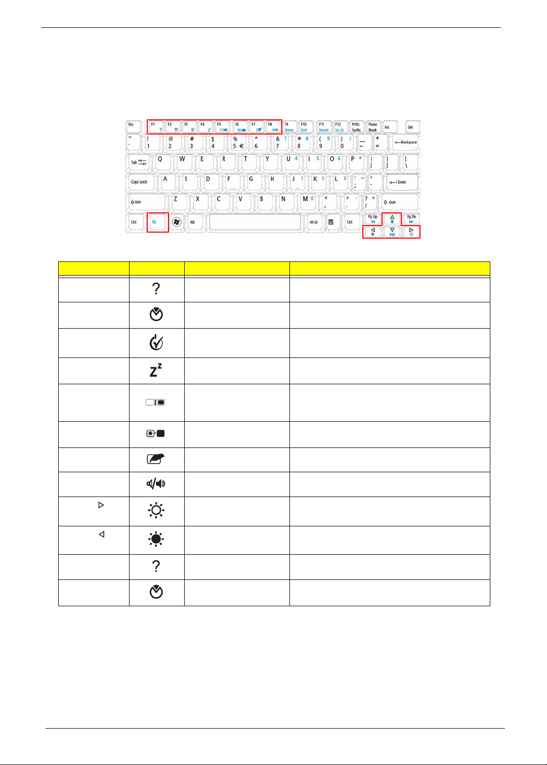
Hot Keys
The computer employs hotkeys or key combinations to access most of the computer’s controls like screen
brightness, volume output and the BIOS utility.
To activate hot keys, press and hold the <Fn> key before pressing the other key in the hotkey combination.
Hotkey Icon Function Description
<Fn> + <F1> Hotkey help Displays help on hotkeys.
<Fn> + <F2> Acer eSettings
Management
<Fn> + <F3> Acer ePower
Management
<Fn> + <F4> Sleep Puts the computer in Sleep mode.
<Fn> + <F5> Display toggle Switches display output between the display
<Fn> + <F6> Screen blank Turns the display screen backlight off to save
<Fn> + <F7> Touchpad toggle Turns the internal touchpad on and off.
<Fn> + <F8> Speaker toggle Turns the speakers on and off.
<Fn> + < > Brightness up Increases the screen brightness.
<Fn> + < > Brightness down Decreases the screen brightness.
<Fn> + <F1> Hotkey help Displays help on hotkeys.
<Fn> + <F2> Acer eSettings
Management
Launches Acer eSettings Management in Acer
Empowering Technology.
Launches Acer ePower Management in Acer
Empowering Technology.
screen, external monitor (if connected) and
both.
power. Press any key to return.
Launches Acer eSettings Management in Acer
Empowering Technology.
14 Chapter 1
Page 25
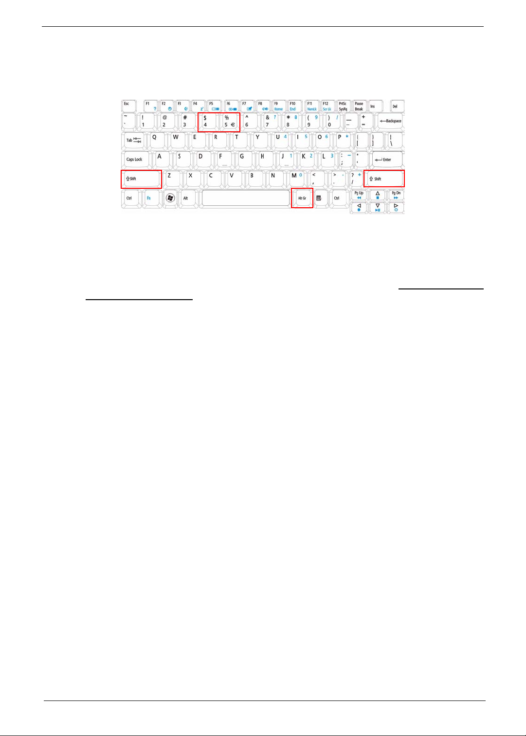
Special Key
You can locate the Euro symbol and the US dollar sign at the upper-center and/or bottom-right of your
keyboard.
The Euro symbol
1. Open a text editor or word processor.
2. Hold <Alt Gr> and then press the <5> key at the upper-center of the keyboard.
NOTE: Note: Some fonts and software do not support the Euro symbol. Please refer to www.microsoft.com/
typography/faq/faq12.htm for more information.
The US dollar sign
1. Open a text editor or word processor.
2. Hold <Shift> and then press the <4> key at the upper-center of the keyboard.
NOTE: This function varies by the operating system version.
Chapter 1 15
Page 26
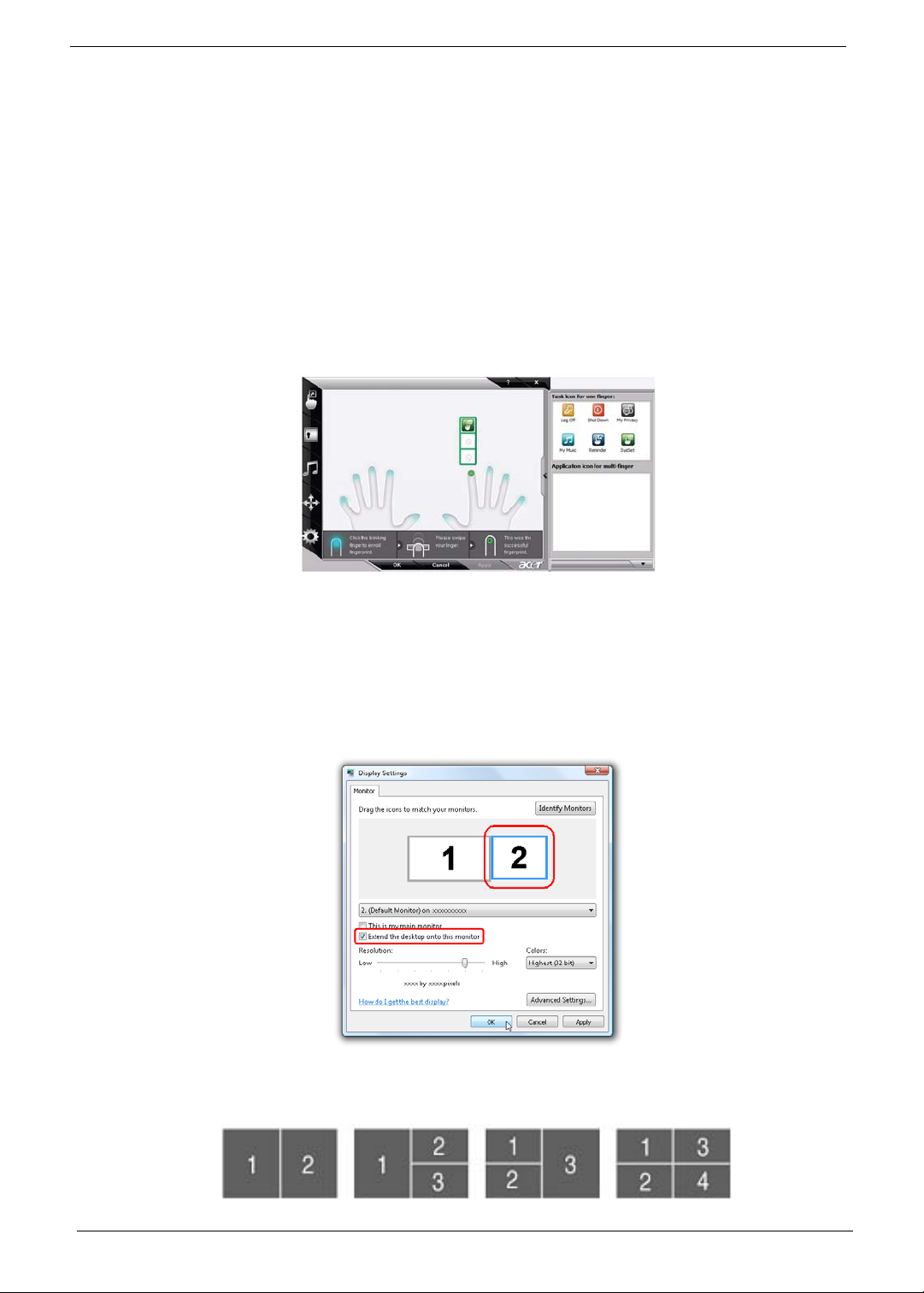
Using the System Utilities
Acer Bio-Protection (only for certain models) Acer Bio-Protection Fingerprint Solution is a multi-purpose
fingerprint software package integrated with the Microsoft Windows operating system. Utilizing the uniqueness
of one's fingerprint features, Acer Bio-Protection Fingerprint Solution has incorporated protection against
unauthorized access to your computer with centralized password management with Password Bank, easy
music player launching with Acer MusicLaunch, secure Internet favorites via Acer MyLaunch, and fast
application/website launching and login with Acer FingerLaunch, while Acer ProfileLaunch can launch up to
three applications/websites from a single finger swipe.
Acer Bio-Protection Fingerprint Solution also allows you to navigate through web browsers and documents
using Acer FingerNav. With Acer Bio-Protection Fingerprint Solution, you can now enjoy an extra layer of
protection for your personal computer, as well as the convenience of accessing your daily tasks with a simple
swipe of your finger!
For more information refer to the Acer Bio-Protection help files.
Acer GridVista (dual-display compatible)
NOTE: This feature is only available on certain models.
To enable the dual monitor feature of the notebook, first ensure that the second monitor is connected, then
select Start, Control Panel, Display and click on Settings. Select the secondary monitor (2) icon in the
display box and then click the check box Extend my windows desktop onto this monitor. Finally, click
Apply to confirm the new settings and click OK to complete the process.
Acer GridVista is a handy utility that offers four pre-defined display settings so you can view multiple windows
on the same screen. To access this function, please go to Start´ All Programs and click on Acer GridVista.
You may choose any one of the four display settings indicated below:
16 Chapter 1
Page 27
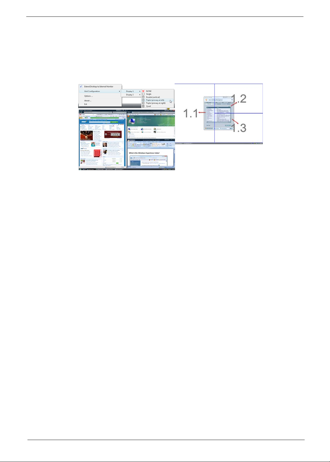
Double (vertical), Triple (primary at left), Triple (primary at right), or Quad Acer Gridvista is dual-display
compatible, allowing two displays to be partitioned independently.
Acer Gridvista is dual-display compatible, allowing two displays to be partitioned independently.
AcerGridVista is simple to set up:
1. Run Acer GridVista and select your preferred screen configuration for each display from the task bar.
2. Drag and drop each window into the appropriate grid.
3. Enjoy the convenience of a well-organized desktop.
NOTE: Please ensure that the resolution setting of the second monitor is set to the manufacturer's
recommended value.
Chapter 1 17
Page 28
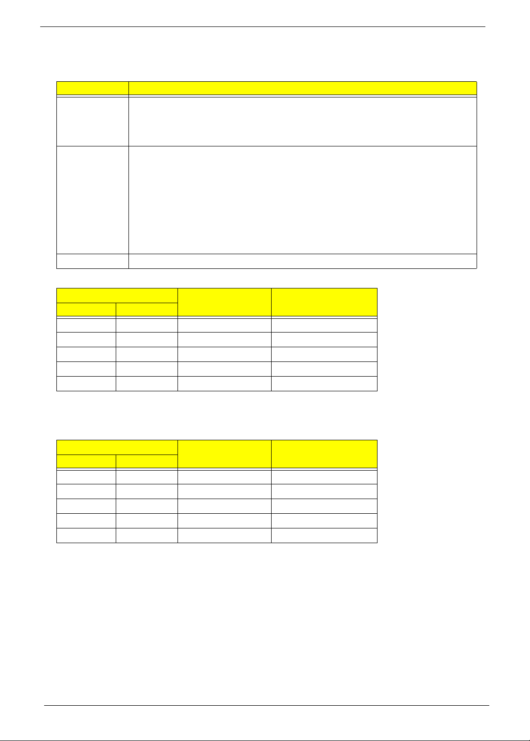
Hardware Specifications and Configurations
Processor
Item Specification
CPU type
Core logic
CPU package Micro uPGA-478 package CPU
CPU Fan True Value Table DIS SKU
CPU Temperature
Core 0 Core 1
50 50 3000 31
60 60 3400 34
70 70 3800 37
77 77 4200 40
85 85 4200 40
• Intel® Core™2 Duo processor based Intel® Celero n pro ce sso r an d Inte l ®
Pentium processor, 667-MHz FSB support on Cantiga GL40 platform
• Intel® Core™2 Duo processors and Intel® Core™2 Extreme processors, 667-
MHz, 800-MHz and 1066-MHz FSB support on Cantiga PM40 platform
• Intel Cantiga GL40 (667MHz FSB supported)/ Intel Cantiga PM40 (667/800/
1066MHz FSB supported)
• ICH9-M
• ENE KB926 for Keyboard Controller, Battery management Unit.
• JMICRON JMB385 for Card Reader, 5 in 1 controller.
• Integrated VGA solution for CANTIGA GL40/ External VGA card for CANTIGA PM
• REALTEK ALC268 for High Definition Audio Codec.
• REALTEK RTL8111C-GR for Giga LAN
Fan Speed (RPM) SPL Spec (dBA)
• Throttling 50%: On= 85°C; OFF=78°C
• OS shut down at 90°C; H/W shut down at 96°C
CPU Fan True Value Table UMA SKU
CPU Temperature
Core 0 Core 1
Fan Speed (RPM) SPL Spec (dBA)
50 50 3000 31
60 60 3400 34
70 70 3700 37
77 77 4000 40
85 85 4000 40
• Throttling 50%: On= 85°C; OFF=78°C
• OS shut down at 90°C; H/W shut down at 96°C
18 Chapter 1
Page 29

BIOS
Item Specification
BIOS vendor InsydeH20
BIOS Version v1.03-T2
BIOS ROM type Flash
BIOS ROM size 1 MB
Supported protocols
• Support Acer UI
• Support multi-boot
• Suspend to RAM (S3)/Disk (S4)
• Va rious hot-keys for system control
• Support SMBUS 2.0, PCI2.3
• ACPI 2.0 compliance with Intel Speed Step Support C1, C2, C3
and S3, S4 for mobile CPU
• DMI utility for BIOS serial number configurable/asset tag
• Support PXE
• Support Y2K solution
• Support Win Flash Wake on LAN from S3
• Wake on LAN form S4 in AC mode
• System information
Cache
Item Specification
Cache controller Built in
Cache size L2 Cache dependent on CPU
System Memory
Item Specification
Memory controller Built in
Memory size 0 MB on board
DIMM socket number 2
Supports memory size per socket 2 GB
Supports maximum memory size 4 GB
Supports DIMM type GL40 supporting DDR II 667 SDRAM memory interface / PM40
supporting DDR II 667/800 SDRAM memory interface
Supports DIMM Speed 667/800 MHz
Chapter 1 19
Page 30
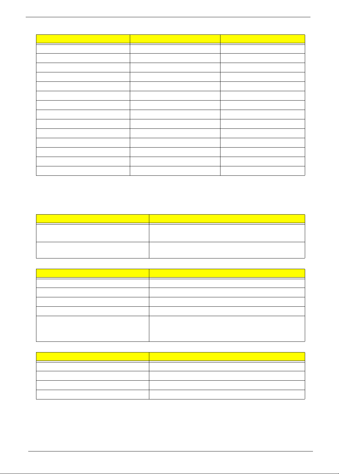
Memory Combinations
Slot 1 Slot 2 Total Memory
0MB 512MB 512MB
0MB 1024MB 1024MB
0MB 2048MB 2048MB
512MB 512MB 1024MB
512MB 1024MB 1536MB
512MB 2048MB 2560MB
1024MB 0MB 1024MB
1024MB 512MB 1536MB
1024MB 1024MB 2048MB
1024MB 2048MB 3072MB
2048MB 0MB 2048MB
2048MB 512MB 2560MB
2048MB 1024MB 3072MB
2048MB 2048MB 4096MB
NOTE: Above table lists some system memory configurations. You may combine DIMMs with various
capacities to form other combinations. On above table, the configuration of slot 1 and slot 2 could be
reversed.
Graphics Controller
Item Specification
Chipset
Features
• Cantiga GL: Intel Integrated Graphic
• Cantiga PM: MXM Graphic Adopter
• Estimated 400-MHz core render clock @ 1.05-V core
voltage
LAN Interface
Item Specification
LAN Chipset Realtek RTL8111C-GR
Supports LAN protocol 10/100/1000 Mbps
LAN connector type RJ45
LAN connector location Left side
Features PCI-E Giga LAN
Support Wake-On-Lan (AC mode S5)
No ASF 2.0/iAMT 4.0
Bluetooth Interface
Item Specification
Chipset Broadcom 2045 & Broadcom 2070
Protocol Bluetooth 2.0
Interface Mini USB modul e and built-in antenna
Connector type Mini USB
20 Chapter 1
Page 31
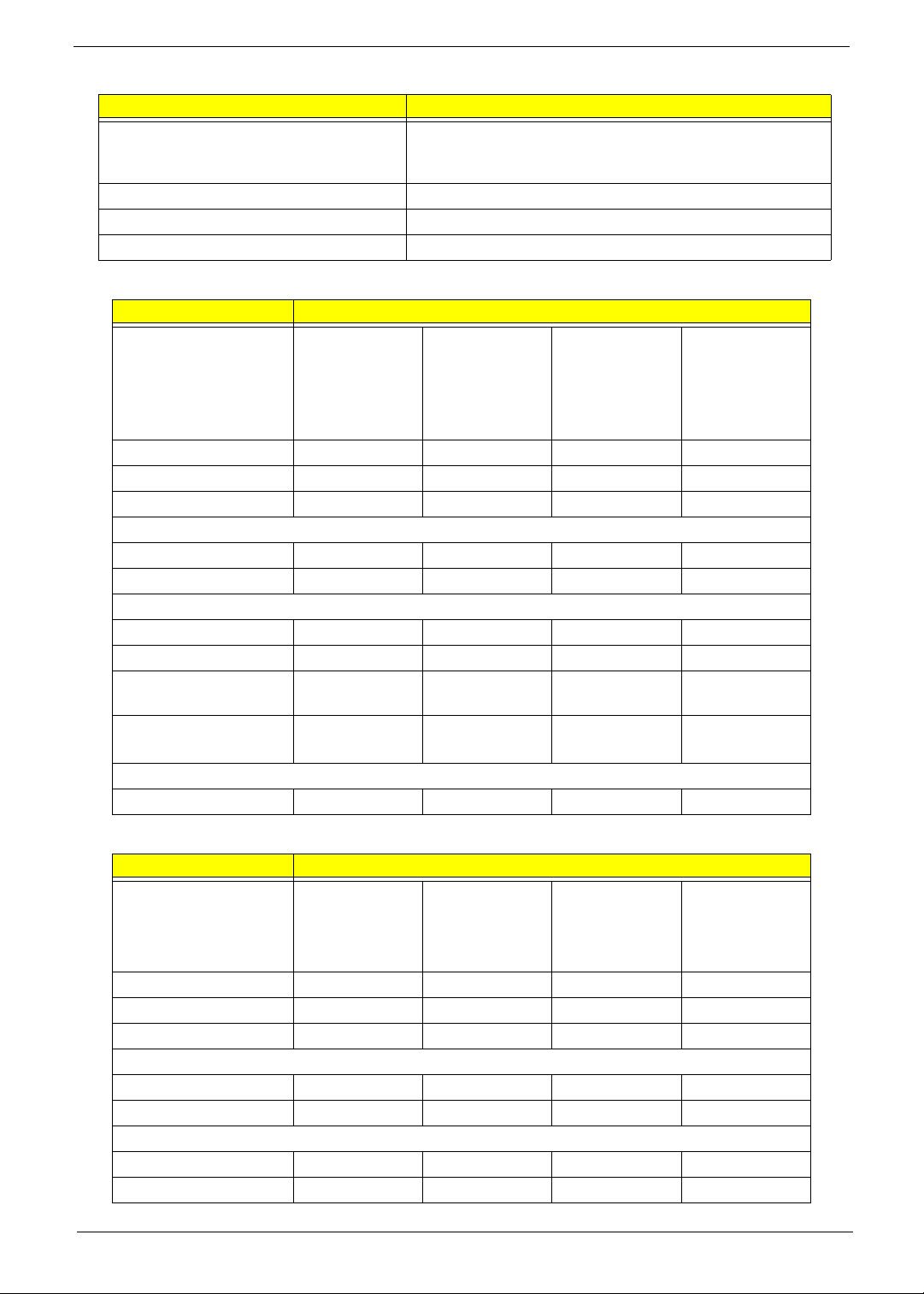
Wireless Module 802.11b/g
Item Specification
Chipset Intel Shirley Peak and Echo Peak (for Centrino platform)
Atheros WLAN XB63 and Broadcom WLAN BCM4312 (for
Non-Centrino)
Data throughput 11~54 Mbps, up to 270 Mbps for Draft-N
Protocol 802.11b+g, Draft-N
Interface PCI bus (mini PCI socket for wireless module)
Hard Disk Drive Interface
Item Specifications
Vendor & Model Name Hitachi
5K250-250
5K250-160
5K250-120
Capacity (MB) 250, 160, 120 320, 160, 120 250, 160, 120 320, 160
Bytes per sector 512 512 512 512
Data heads 4, 3, 2 4, 2, 2 4, 3, 2 4, 2
Drive Format
Disks 2, 2, 1 2, 1, 1 2, 2, 1 2 or 1, 1
Spindle speed (RPM) 5400 5400 5400 5400
Performance Specifications
Buffer size 8 MB 8 MB 8 MB 8 MB
Interface SATA SATA SATA SATA
Internal transfer rate
(Mbits/sec, max)
I/O data transfer rate
(Mbytes/sec max)
DC Power Requirements
Voltage 5V ±5% 5V ±5% 5V ±5% 5V ±5%
643 ~ 665 674 ~ 729 778 352
150 / 300 300 300 150
Hitachi
5K350-250
5K350-160
5K350-120
Segate
ST9250827AS
ST9160827AS
ST9120817AS
Segate
ST9320320AS
ST9160310AS
Item Specifications
Vendor & Model Name Toshiba
MK2546GSX
MK1646GSX
MK1246GSX
Capacity (MB) 250, 160, 120 120 250, 120 320, 160
Bytes per sector 512 512 512 512
Data heads 4, 3, 2 2 4, 2 4, 2
Drive Format
Disks 2, 2, 1 1 2, 1 2, 1
Spindle speed (RPM) 5400 5400 5400 5400
Performance Specifications
Buffer size 8 MB 8 MB 8 MB 8 MB
Interface SATA SATA SATA SATA
Chapter 1 21
Toshiba
MK1252GSX
WD
WD2500BEVS
WD1200BEVS
WD
WD3200BEVT
WD1600BEVT
Page 32
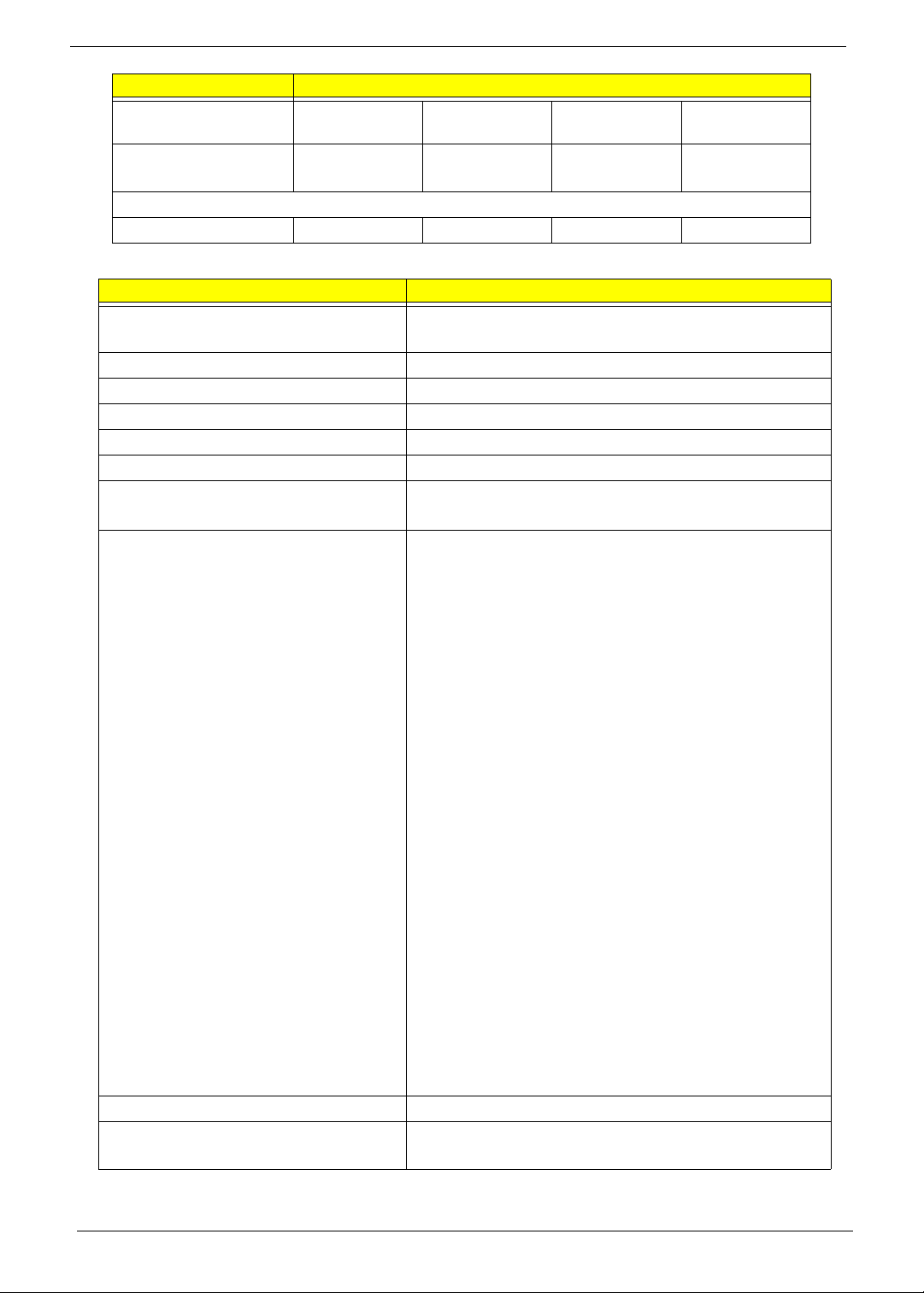
Item Specifications
Internal transfer rate
(Mbits/sec, max)
I/O data transfer rate
370 ~ 730
typical
400 ~ 794
typical
850 Mbits/s
maximum
850 Mbits/s
maximum
300 300 150 maximum 300 maximum
(Mbytes/sec max)
DC Power Requirements
Voltage 5V ±5% 5V ±5% 5V ±5% 5V ±5%
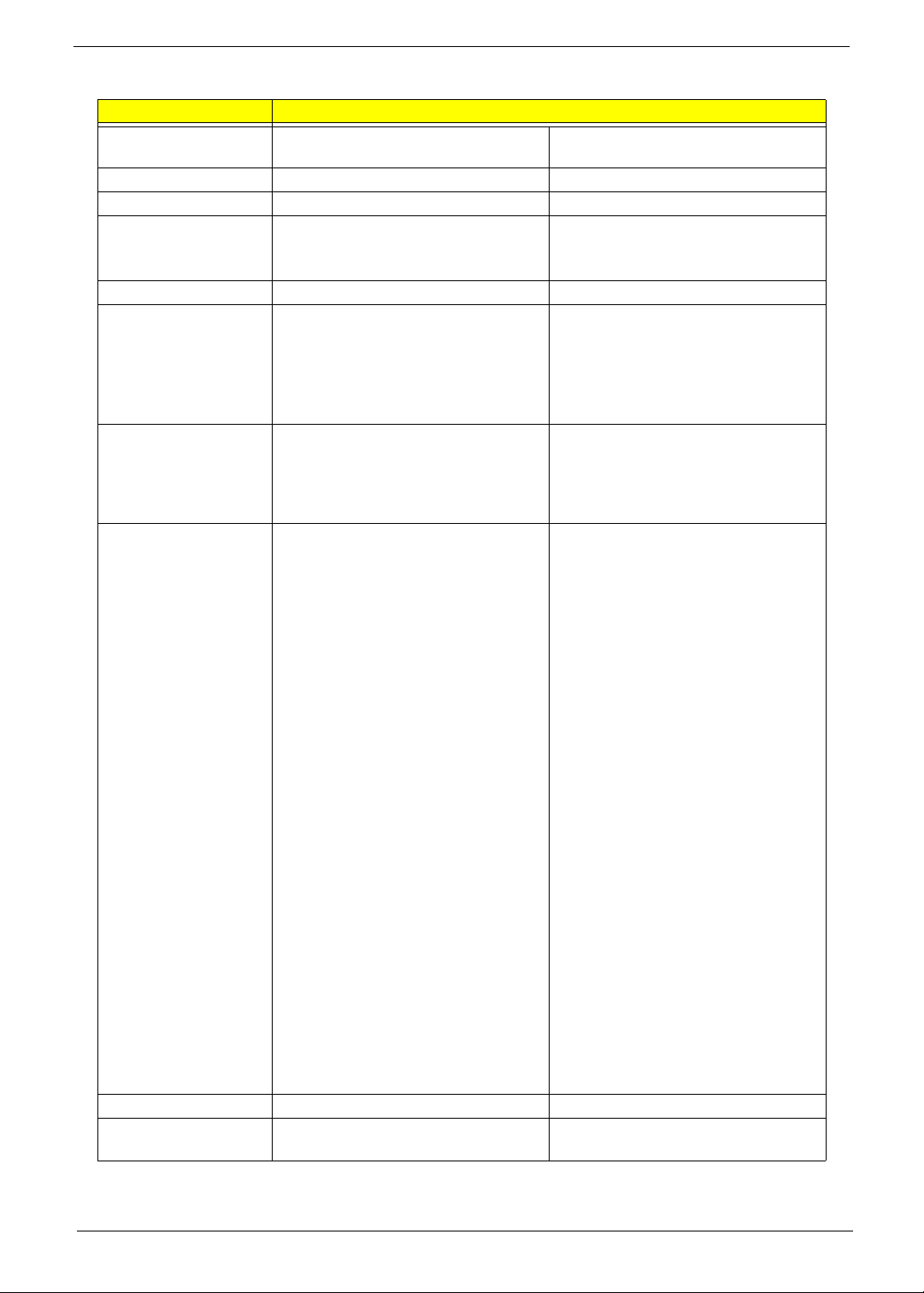
Combo Drive Module
Item Specification
Manufacturer and Model Sony DL 24X CRX890S
Toshiba DL 24X TS-L463A
Type Drawer type
Interface SATA
Data Transfer Mode PIO Mode4
Buffer Memory Size 2 MB
Maximum Write Speed
Maximum Read Speed
• CD 3,600 KB/sec
• CD 3,600 KB/sec
• DVD 10,800 KB/sec
Formats Supported CD
• CD-DA (Red Book) - Standard Audio CD & CD-TEXT
• CD-ROM (Yellow Book Mode1 & 2) - Standard Data
• CD-ROM XA (Mode2 Form1 & 2) - Photo CD, Multi-
Session
• CD-I (Green Book, Mode2 Form1 & 2, Ready, Bridge)
• CD-Extra/ CD-Plus (Blue Book) - Audio & Text/Video
• Video-CD (White Book) - MPEG1 Video
• CD-R (Orange Book Part ‡U)
• CD-RW & HSRW (Orange Book Part‡V Vol ume1 &
Volume2)
• Super Audio CD (SACD) Hybrid type
• US & US+ RW
DVD
• DVD-ROM (Book 1.02), DVD-Dual
• DVD-Video (Book 1.1)
• DVD-R (Book 1.0, 3.9G)
• DVD-R (Book 2.0, 4.7G) - General & Authoring
• DVD+R (Version 1.0)
• DVD-RW, DVD+RW
• DVD+R DL
• DVD-R DL
• Support CPRM (read)
• Support VCPS (read)
Power Supply DC +5V / 1.3A
Voltage Allowance DC +5V
(5% (Operating), DC +5V(8% (Start Up))
22 Chapter 1
Page 33
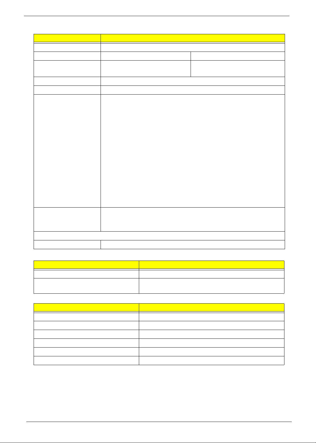
Super-Multi Combo Module
Item Specification
Manufacturer and Model Sony DL 8X AD-7560S
Toshiba DL 8X TS-L633A
Type Drawer type Drawer loading
Interface SATA Serial ATA Revision 2.6
Data Transfer Modes
• PIO Mode4
• DMA Multiword Mode2
• ULTRA DMA Mode2
Buffer Memory Size 2 MB 2 MB
Maximum Write Speed
Maximum Read Speed
• CD-R Max. 24X (3,600 KB/sec)
• DVD+RW Max 8X (10,800 KB/sec)
• CD 3,600 KB/sec
• DVD 10,800 KB/sec
Format Compatibility CD
• CD-DA (Red Book) - Standard Audio
CD & CD-TEXT
• CD-ROM (Yellow Book Mode1 & 2) -
Standard Data
• CD-ROM XA (Mode2 Form1 & 2) -
Photo CD, Multi-Session
• CD-I (Green Book, Mode2 Form1 &
2, Ready, Bridge)
• CD-Extra/ CD-Plus (Blue Book) -
Audio & Text/Video
• Video-CD (White Book) - MPEG1
Video
• CD-R (Orange Book Part ‡U)
• CD-RW & HSRW (Orange Book Part
IV Volume1 & Volume2)
• Super Audio CD (SACD) Hybrid type
• US & US+ RW
DVD
• DVD-ROM (Book 1.02), DVD-Dual
• DVD-Video (Book 1.1)
• DVD-R (Book 1.0, 3.9G)
• DVD-R (Book 2.0, 4.7G) - General &
Authoring
• DVD+R (Version 1.0)
• DVD+RW
• DVD-RW (Non CPRM & CPRM)
• DVD±R Dual
• DVD-RAM
Power Supply DC +5V / 1.3A 5V
Voltage Allowance DC +5V
(5% (Operating), DC +5V(8% (Start Up))
Pioneer DVR-TD08RS
Gen1i 1.5Gbits / sec
• 8X Zone CLV at DVD-R / +R,
DVD+RW
• 6X Zone CLV at DVD-R DL / +R DL,
DVD-RW
• 5X Zone CLV at DVD-RAM
• 24X Zone CLV at CD-R / RW
• 8X CAV at DVD-ROM SL, DVD-R /
+R, -RW / +RW, DVD-ROM DL,
DVD-R DL / +R DL
• 5X Zone CLV at DVD-RAM
• 24X CAV at CD-ROM, CD-R / RW
• KODAK Photo CD Single and Multi-
session
• CD Extra (CD PLUS)
• Video CD
• CD text data (Read / Write)
• CD-R discs (Read / Write)
• CD-RW discs (Read / Write)
• DVD-ROM
• DVD-R Ver.2.0 & 2.1 for General
(Read / Write)
• DVD-R DL Ver.3.0 (Read/Write)
• DVD-RW Ver.1.0 & 1.1 & 1.2 (Read /
Write)
• DVD+R Ver.1.3 (Read/Write)
• DVD+R DL Ver1.0 & 1.1 (Read /
Write)
• DVD+RW Ver.1.3 (Read/Write)
• DVD+RW high speed Ver.1.0 (Read/
Write)
• DVD-RAM Ver.2.0 & 2.1 & 2.2
±5% (operating)
-8% (startup)
Chapter 1 23
Page 34
Item Specification
Vendor & model name HLDS/GSA-T50N, Philips DS-8A2S, Sony/AD-7560S, Toshiba Digi/TS-L633A
Performance S p ecification With CD Diskette With DVD Diskette
Transfer rate (MB/sec) Sustained:
Max 3.5 Mbytes/sec
Buffer Memory 2MB
Interface SATA
Applicable disc format Applicable media types:
Writing:
Confirms to DVD+R Version 1.2 and DVD+RW Version 1.3 / DVD+R DL
Version 1.0 /DVD-R Version 2.0 / DVD-RW Version 1.2 / DVD-R DL Version
3.0.
Reading:
DVD single/dual layer (PTP, OTP), DVD-R single/dual layer
DVD+R single/double layer
DVD-RW
DVD+RW
CD-DA
CD-ROM
CD-ROM/XA
Photo-CD, Multi-session, Video CD
CD-I FMV, CD Extra, CD Plus, CD-R, and CD-RW
Loading mechanism Drawer (Solenoid Open)
Tact SW (Open)
Emergency Release (draw open hole)
Power Requirement
Input Voltage DC 5 V +/- 5%
Sustained:
Max 10 Mbytes/sec
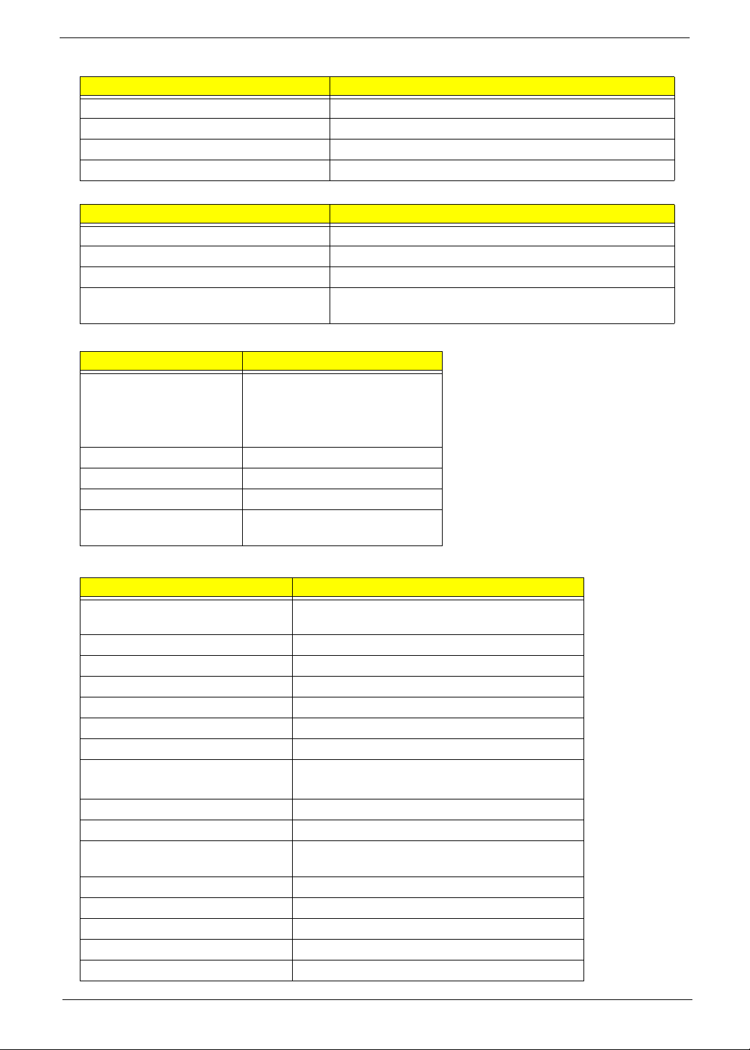
Card Reader
Item Specification
Chipset JMICRON JMB385
Features Combo (SD/MMC/MS/MS Duo/MS-HG (1/4/8-bit) & xD
access) supports D3 Enhancement (D3E) mode
Audio Interface
Item Specification
Audio Controller REALTEK ALC268
Audio onboard or optional Onboard
Mono or Stereo Stereo
Resolution 2 Channel
Internal microphone 1 x Analog MIC
Internal speaker / Quantity 2 x stereo speaker
24 Chapter 1
Page 35
USB Interface
Item Specification
Chipset ICH9M
USB Compliancy Level 2.0
Number of USB port 2
Location Left Side
Keyboard
Item Specification
Keyboard controller KB926
Total number of keypads 88/89/93
Windows logo key Yes
Internal & external keyboard work
Yes
simultaneously
Battery
Item Specification
Vendor & model name Sanyo AS07A
Sony AS07A
Simplo AS07A
Panasonic AS07A
Battery Type Li-ion
Pack capacity 4400 mAh
Number of battery cell 6
Package configuration 3 cells in series, 2 series in
parallel
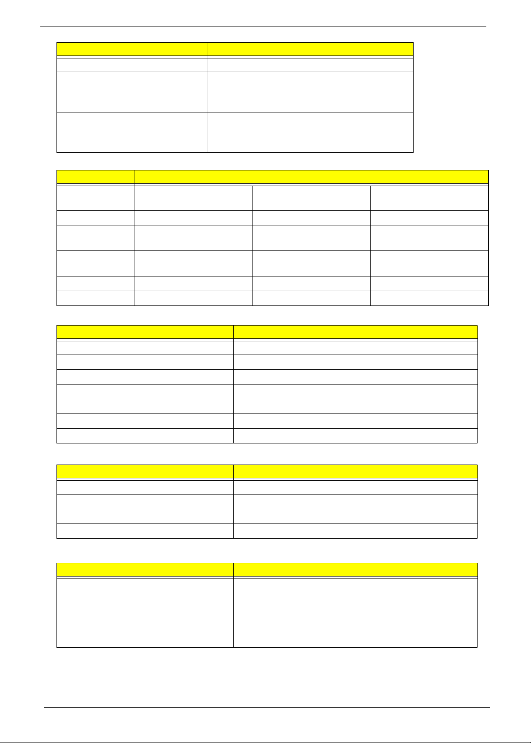
LCD 14.1”
Item Specification
Vendor/model name LG.Philips/LP141WX3, AUO/B141EW04 V4,
Chimei/N141I3 - L02, Samsung/LTN141W3-L01
Screen Diagonal (mm) 14.1 inches
Active Area (mm) 303.74 x 189.84 mm
Display resolution (pixels) 1280 x 800 WXGA
Pixel Pitch 0.2373 × 0.2373 mm
Pixel Arrangement R.G.B. Vertical Stripe
Display Mode Transmissive mode, normally white
2
200 cd/m2(Typ.5 point)
Typical White Luminance (cd/m
)
also called Brightness
Luminance Uniformity 1.3 max.
Contrast Ratio 300 minimum
Response Time (Optical Rise
16
Time/Fall Time) msec
Nominal Input Voltage VDD +3.3V
Typical Power Consumption (watt) 1.4W max.
Weight (without inverter) 400g max.
Physical Size (mm) 319.5 (±0.5) x 205.5 (± 0.5) x 5.5 max.
Electrical Interface 3.3V LVDS interface with 1 pixel/clock
Chapter 1 25
Page 36
Item Specification
Support Color g reater than 262144
Viewing Angle (degree)
Horizontal: Right/Left
Vertical: Upper/Lower
Minimum: 40/40, Typical: 45/45
Minimum: 10/30, Typical: 20/35
Temperature Range (°C)
Operating
Storage (shipping)
0 to +50
-20 to +60
LCD Camera
Item Specification
Vendor Bison
BN30V4O7-010
Sirtek
CN0314-SN30-OV03-1
Suyin
CN1014-S36B-OV01
Focusing range Fixed 40 cm to infinity 40 cm to infinity
Dimension
(L x W x H mm)
Sensor Up to SXGA (1280x1024)
W9 * L65 * H5.3 mm 65 * 9.0 * 5.30 mm
+/-0.20 mm
OV7725 CMOS Sensor
size CMOS sensor
350K Pixel
65 * 9.0 * 5.26 mm
1.0 Megabit CMOS
Sensor
Pixel Resolution 640(H) * 480(V) VGA 640 * 480 1280X800
Pixel Size 6.0µm * 6.0µm 6.0 µm * 6.0 µm 3.0µm * 3.0µm
LCD Inverter
Item Specification
Vendor & model name YEC YNV-C01H
Brightness conditions N/A
Input voltage (V) 9~20(V)
Input current (mA) Typical 0.33(mA)
Output voltage (V, rms) Typical 650 Vrms
Output current (mA, rms) MAX. 6.8mA
Output voltage frequency (k Hz) 45~65 (KHz)
AC Adapter
Item Specification
Input rating 100~240Vac/ 50-60Hz
Maximum input AC current 1.5A
Inrush current No damage
Efficiency Meet EPA level-4 requirement
System Power Management
Item Specification
Features
• Mech. Off (G3)
• Soft Off (G2/S5)
• Working (G0/S0)
• Suspend to RAM (S3)
• Save to Disk (S4)
26 Chapter 1
Page 37

Chapter 2
System Utilities
BIOS Setup Utility
The BIOS Setup Utility is a hardware configuration program built into your computer’s BIOS (Basic Input/
Output System).
Y our computer is already properly configured and optimized, and you do not need to run this utility . However, if
you encounter configuration problems, you may need to run Setup. Please also refer to Chapter 4
Troubleshooting when problem arises.
To activate the BIOS Utility, press F2 during POST (when “Press <F2> to enter Setup” message is prompted
on the bottom of screen).
Press F2 to enter setup. The default parameter of F12 Boot Menu is set to “disabled”. If you want to change
boot device without entering BIOS Setup Utility, please set the parameter to “enabled”.
Press <F12> during POST to enter multi-boot menu. In this menu, user can change boot device without
entering BIOS SETUP Utility.
Navigating the BIOS Utility
There are six menu options: Information, Main, Advanced, Security, Boot, and Exit.
Follow these instructions:
• To choose a menu, use the left and right arrow keys.
• To choose an item, use the up and down arrow keys.
• To change the value of a parameter, press F5 or F6.
• A plus sign (+) indicates the item has sub-items. Press Enter to expand this item.
• Press Esc while you are in any of the menu options to go to the Exit menu.
• In any menu, you can load default settings by pressing F9. You can also press F10 to save any
changes made and exit the BIOS Setup Utility.
NOTE: You can change the value of a parameter if it is enclosed in square brackets. Navigation keys for a
particular menu are shown on the bottom of the screen. Help for parameters are found in the Item
Specific Help part of the screen. Read this carefully when making changes to parameter values. Please
note that system information is subject to different models.
Chapter 2 27
Page 38
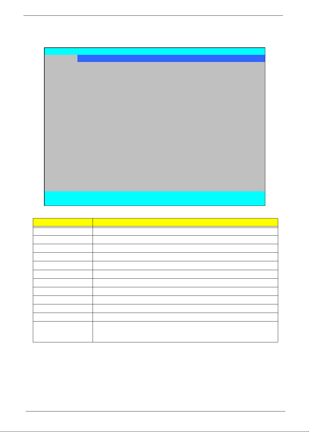
Information
The Information screen displays a summary of your computer hardware information.
InsydeH20 Setup Utility Rev. 3.5
Inform a tion Main Security Boot Exit
CPU Type: Int el (R) Core (TM)2 Duo CPU P8400 @ 2.26GHz
CPU Speed: 2.26GHz
HDD Mod e l Name: W DC WD1 6 0 0 BE VT-22 ZCT0
HDD Se r ial Number : WD-WXHY073 7 3 69 3
ATAPI Model Name: TSSTcorp CDDVDW TS-L633A
System BIOS Version: v1.03-T2
VGA BIOS Version: Intel V1625
Seri al Number: LXJAW50 0068221C97C1601
Ass et Tag Number:
Product Name: A spire 4730Z
Manufacturer Name: Acer
UUID: 309E6330-6B60-16FA-ADF9-001EEC448964
F1 Help ↑↓ Select Item F5/F6 Change Values F9 Set up Defaul t
ESC Exit ←→ Select Menu Enter SelectXSubMenu F10 S ave and Exit
NOTE: The system information is subject to different models.
Parameter Description
CPU Type This field shows the CPU type and speed of the system.
CPU Speed This field shows the speed of the CPU.
HDD Model Name This field shows the model name of HDD installed on primary IDE master.
HDD Serial Number This field displays the serial number of HDD installed on primary IDE master.
ATAPI Model Name This field shows the model name of the Optical device installed in the system.
System BIOS Version Displays system BIOS version.
VGA BIOS Version This field displays the VGA firmware version of the system.
Serial Number This field displays the serial number of this unit.
Asset Tag Number Th is field displays the asset tag number of the system.
Product Name This field shows product name of the system.
Manufacturer Name This field displays the manufacturer of this system.
UUID Number Universally Unique Identifier (UUID) is an identifier standard used in software
construction, standardized by the Open Software Foundation (OSF) as part of
the Distributed Computing Environment (DCE).
28 Chapter 2
Page 39
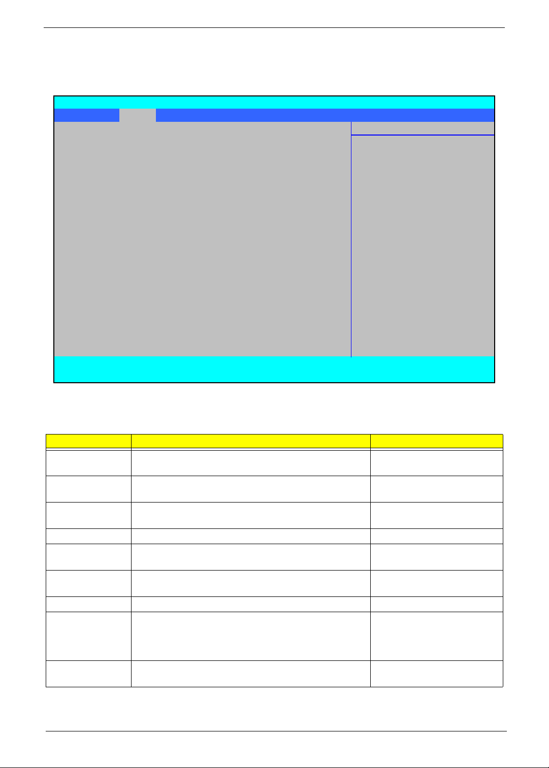
Main
The Main screen allows the user to set the system time and date as well as enable and disable boot option
and recovery.
InsydeH20 Setup Utility Rev. 3.5
Informati on Main Security Boot Exit
Item Specific Help
Sy st em Time [ 13: 04:04] This is t he help for the
Sy st em Dat e [06/ 04/ 2008] hour field. V al id range
is from 0 to 23.
Total Mem ory 2047 M B INCREASE/REDUCE : F5/F6
Video M em ory [64M B ]
Quic k B oot [Enabled]
Network B oot [E nabl ed]
F12 B oot M enu [ Disabled]
D2D Recovery [Enabled]
SA TA Mode [A HCI]
F1 Help ↑↓ Selec t Item F5/F6 Change Values F9 Setup Default
ESC Exit
NOTE: The screen above is for your reference only. Actual values may differ.
The table below describes the parameters in this screen. Settings in boldface are the default and suggested
parameter settings.
Parameter Description Format/Option
System Time Sets the system time. The hours are displayed with 24-
System Date Sets the system date. Format MM/DD/YYYY
Total Memory This field reports the memory size of the system.
Video Memory
Quick Boot Allows startup to skip certain tests while booting,
Network Boot Enables, disables the system boot from LAN (remote
F12 Boot Menu Enables, disables Boot Menu during POST. Option: Disabled or Enabled
D2D Recovery Enables, disables D2D Recovery function. The function
SATA Mode Control the mode in which the SATA controller should
Selec t Menu Enter SelectXSubMenu F10 Save and E xit
←→
Format: HH:MM:SS
hour format.
Memory size is fixed to 2047 MB.
Shows the video memory size. VGA Memory size=64 MB
decreasing the time needed to boot the system.
server).
allows the user to create a hidden partition on hard disc
drive to store operation system and restore the system
to factory defaults.
operate.
(hour:minute:second)
(month/day/year)
N/A
N/A
Option: Enabled or Disabled
Option: Enabled or Disabled
Option: Enabled or Disabled
Option: AHCI or IDE Mode
NOTE: The sub-items under each device will not be shown if the device control is set to disable or auto. This is
because the user is not allowed to control the settings in these cases.
Chapter 2 29
Page 40
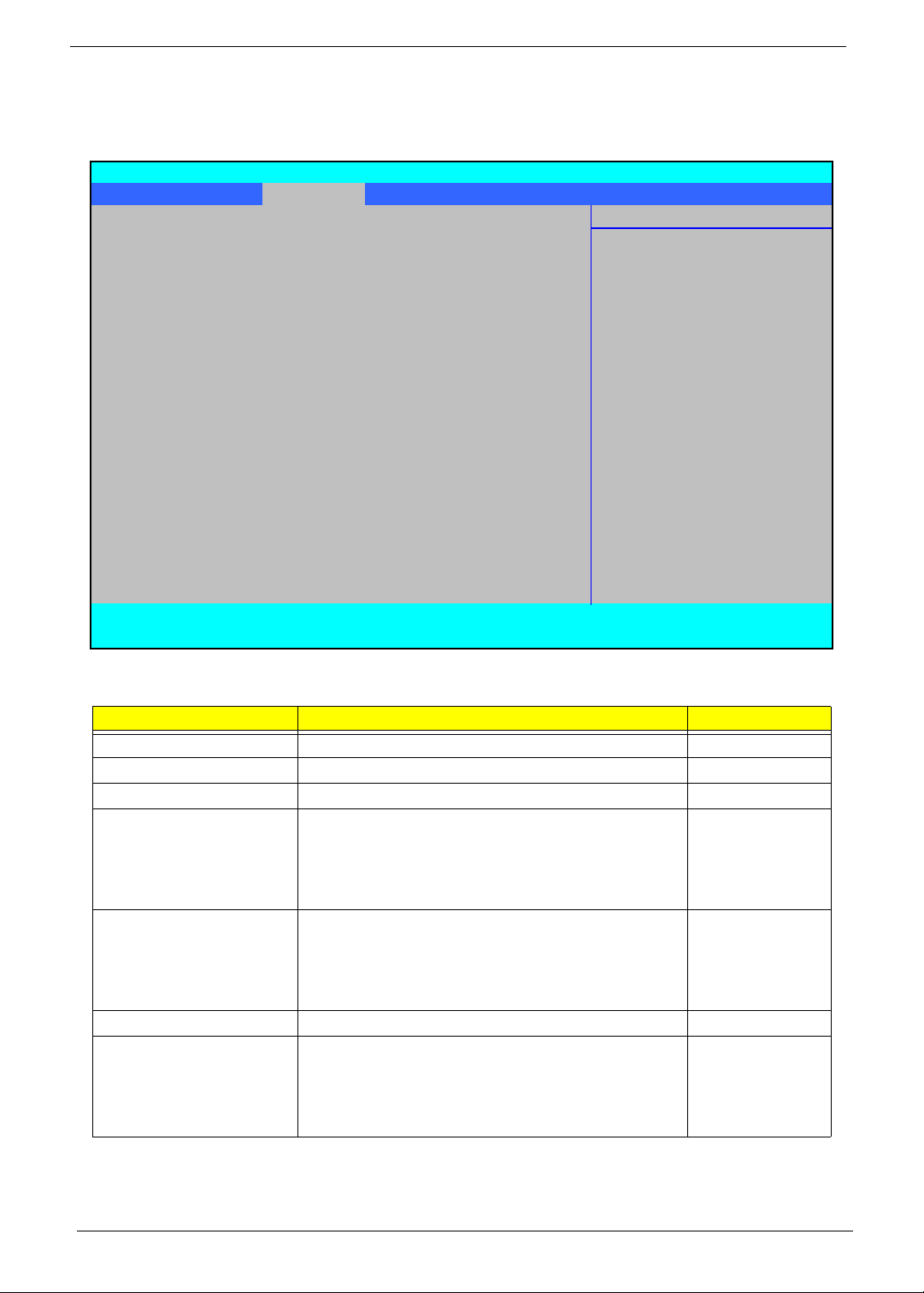
Security
The Security screen contains parameters that help safeguard and protect your computer from unauthorized
use.
Insy deH20 Set up Ut ili t y Rev. 3. 5
Informati on Main Security Boot Exit
Item S pec i fic Help
Supervis or P as sword Is: Clear Instal l or Change the
User P assword Is: Clear password and t he lengt h
HDD Pas sword Is: Clear of password m us t be l es s
than eight words .
Set S upervis or Pas sword
Set User Password
Set Hdd Password
Power on pas sword [Enabl ed]
F1 Help ↑↓ Select Item F5/F6 Change Values F9 Set up Default
ESC Exit
The table below describes the parameters in this screen. Settings in boldface are the default and suggested
parameter settings.
Parameter Description Option
Supervisor Password Is Shows the se tting of the Supervisor password Clear or Set
User Password Is Shows the setting of the user password. Clear or Set
HDD Password Is Shows the setting of the hard disk password. Clear or Set
Set Supervisor Password Press Enter to set the supervisor password. When
Set User Password Press Enter to set the user password. When user
Set HDD Password Enter HDD Password.
Power on password Defines whether a password is required or not while
Select Menu Enter SelectXSubMenu F10 Save and Exit
←→
set, this password protects the BIOS Setup Utility
from unauthorized access. The user can not either
enter the Setup menu nor change the value of
parameters.
password is set, this password protects the BIOS
Setup Utility from unauthorized access. The user can
enter Setup menu only and does not have right to
change the value of parameters.
the events defined in this group happened. The
following sub-options are all requires the Supervisor
password for changes and should be grayed out if the
user password was used to enter set u p.
Enabled or
Disabled
NOTE: When you are prompted to enter a password, you have three tries before the system halts. Don’t forget
your password. If you forget your password, you may have to return your notebook computer to your
dealer to reset it.
30 Chapter 2
Page 41
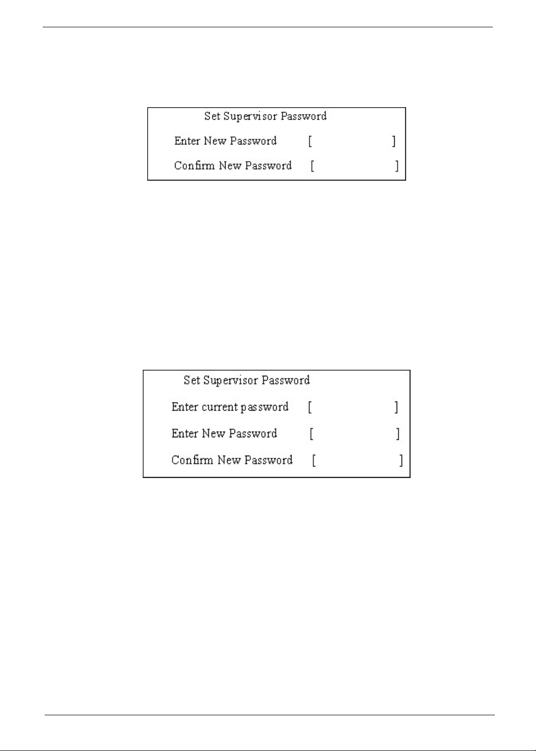
Setting a Password
Follow these steps as you set the user or the supervisor password:
1. Use the ↑ and ↓ keys to highlight the Set Supervisor Password parameter and press the Enter key. The
Set Supervisor Password box appears:
2. Type a password in the “Enter New Password” field. The password length can not exceeds 8
alphanumeric characters (A-Z, a-z, 0-9, not case sensitive). Retype the password in the “Confirm New
Password” field.
IMPORTANT:Be very careful when typing your password because the characters do not appear on the screen.
3. Press Enter. After setting the password, the computer sets the User Password parameter to “Set”.
4. If desired, you can opt to enable the Password on boot parameter.
5. When you are done, press F10 to save the changes and exit the BIOS Setup Utility.
Removing a Password
Follow these steps:
1. Use the ↑ and ↓ keys to highlight the Set Supervisor Password parameter and press the Enter key. The
Set Password box appears:
2. Type the current password in the Enter Current Password field and press Enter.
3. Press Enter twice without typing anything in the Enter New Password and Confirm New Password fields.
The computer then sets the Supervisor Password parameter to “Clear”.
4. When you have changed the settings, press u to save the changes and exit the BIOS Setup Utility.
Chapter 2 31
Page 42
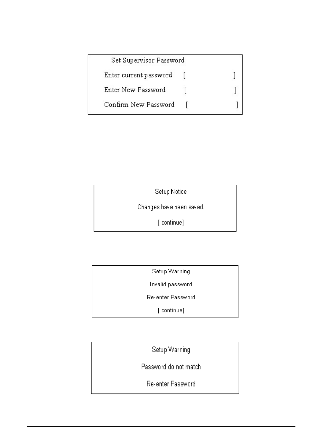
Changing a Password
1. Use the ↑ and ↓ keys to highlight the Set Supervisor Password parameter and press the Enter key. The
Set Password box appears.
2. Type the current password in the Enter Current Password field and press Enter.
3. Type a password in the Enter New Password field. Retype the password in the Confirm New Password
field.
4. Press Enter. After setting the password, the computer sets the User Password parameter to “Set”.
5. If desired, you can enable the Password on boot parameter.
6. When you are done, press F10 to save the changes and exit the BIOS Setup Utility.
If the verification is OK, the screen will display as following.
The password setting is complete after the user presses Enter.
If the current password entered does not match the actual current password, the screen will show you the
Setup Warning.
If the new password and confirm new password strings do not match, the screen will display the following
message.
32 Chapter 2
Page 43
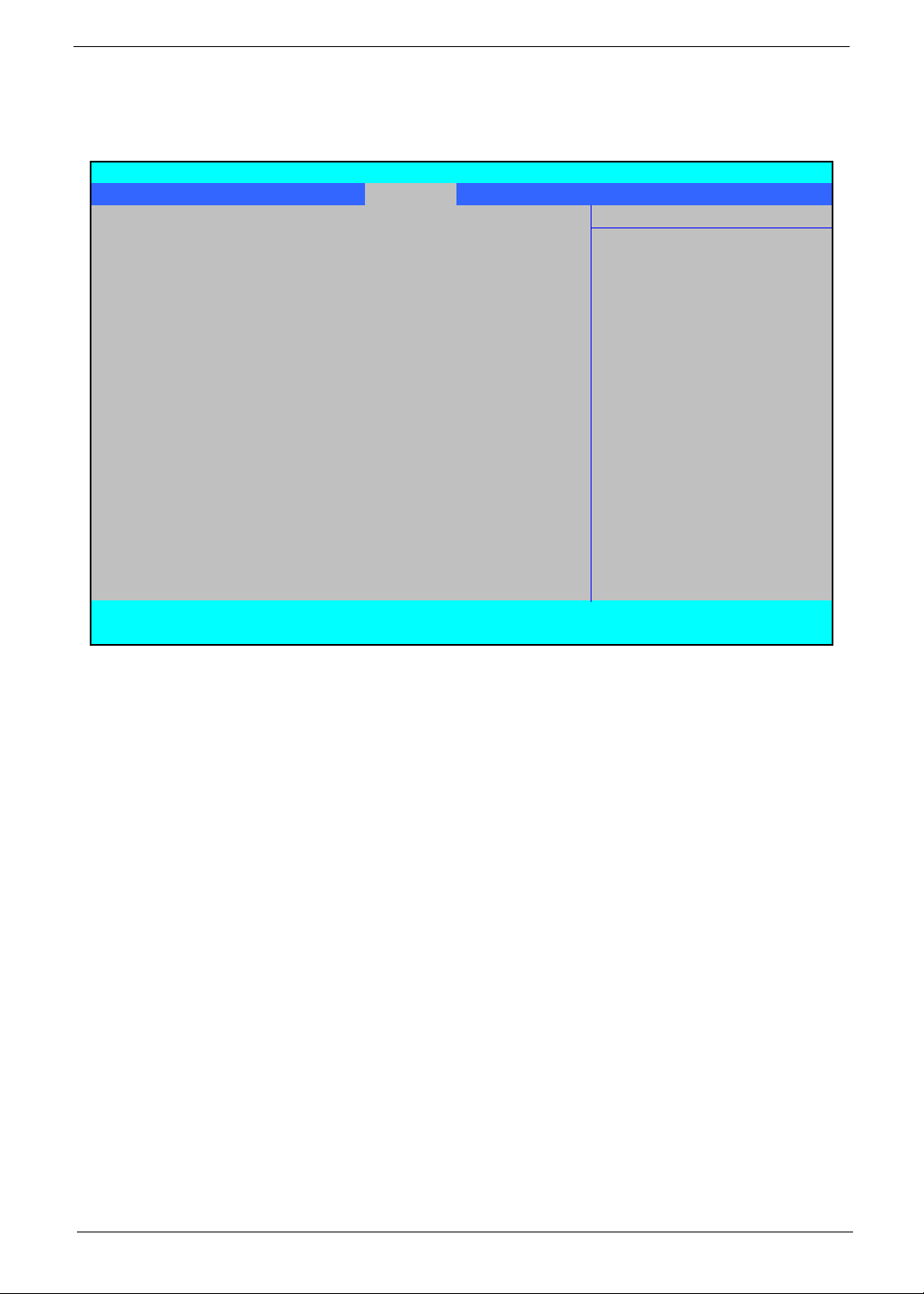
Boot
This menu allows the user to decide the order of boot devices to load the operating system. Bootable devices
includes the USB diskette drives, the onboard hard disk drive and the DVD drive in the module bay.
Insy deH20 S et up Ut ili t y Rev. 3. 5
Informati on Main Sec urit y Boot Exit
Item S pec i fic Help
Boot priorit y order: Use <↑> or <↓> to select
a device, t hen pres s
1. IDE0 : WDC WD1600BE V T-22ZCT0 <F5> t o m ove it down the
2. IDE1 : TSS Tcorp CDDVDW TS-L633A li s t , or <F 6> t o m ove
3. US B F DD : it up t he list . P res s
4. Net work B oot : Realt ek B oot A gent <E s c> t o es c ape t he m enu
5. US B HDD :
6. USB CDRO M :
F1 Help ↑↓ Selec t Item F5/F6 Change Values F9 Setup Default
ESC Exit
Selec t Menu Enter SelectXSubMenu F10 Save and Exit
←→
Chapter 2 33
Page 44
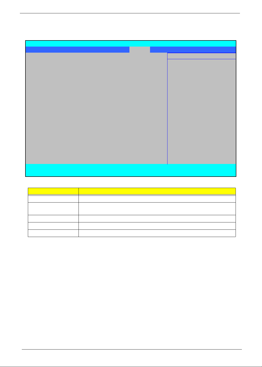
Exit
The Exit screen allows you to save or discard any changes you made and quit the BIOS Utility.
Insy deH20 S et up Ut ilit y Rev. 3. 5
Inform at ion Main S ec urity Boot Exit
Item S pec ific Help
Exit S aving Changes Ex it S y st em S et up and
Exit Dis carding Changes save your changes t o
Load Set up Defaults CMOS.
Discard Changes
Save Changes
F1 Help ↑↓ Selec t Item F5/F6 Change Valies F9 Set up Default
ESC Exit
The table below describes the parameters in this screen.
Parameter Description
Exit Saving Changes Exit System Setup and save your changes to CMOS.
Exit Discarding
Changes
Load Setup Default Load default values for all SETUP item.
Discard Changes Load previous values from CMOS for all SETUP items.
Save Changes Save Setup Data to CMOS.
Select M enu Enter SelectXSubMenu F10 Save and Exit
←→
Exit utility without saving setup data to CMOS.
34 Chapter 2
Page 45
BIOS Flash Utility
The BIOS flash memory update is required for the following conditions:
• New versions of system programs
• New features or options
• Restore a BIOS when it becomes corrupted.
Use the Phlash utility to update the system BIOS flash ROM.
NOTE: Create a Crisis Recovery Media (such as USB HDD) before you use the Phlash utility.
NOTE: Do not install memory-related drivers (XMS, EMS, DPMI) when you use the Phlash.
NOTE: Please use the AC adaptor power supply when you run the Phlash utility. If the battery pack does not
contain enough power to finish BIOS flash, the system will not boot as the BIOS is not loaded.
Perform the following steps to use the Flash Utility:
1. Press F2 during boot to enter the Setup Menu.
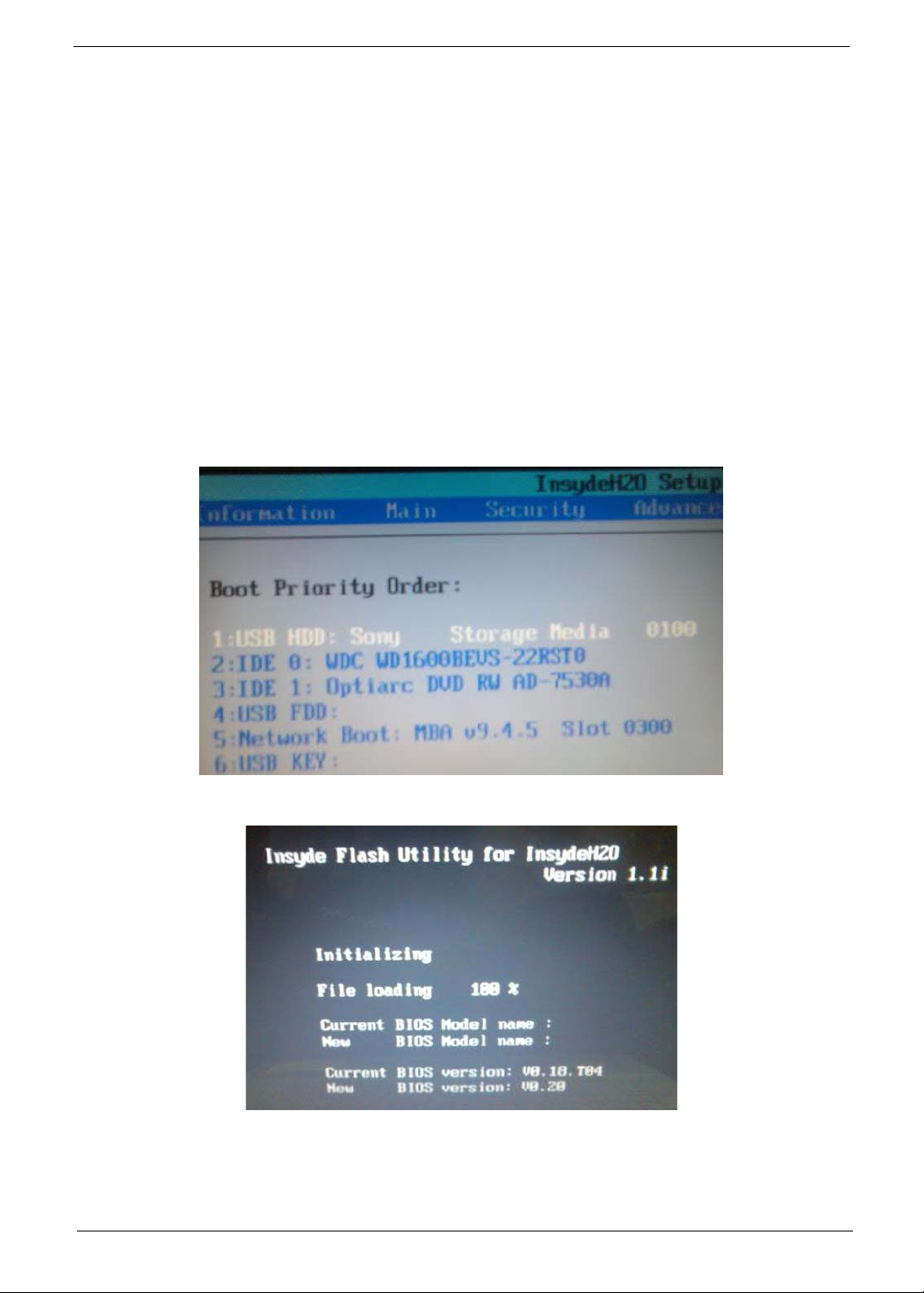
2. Select Boot Menu to modify the boot priority order, for example, if using USB HDD to Update BIOS, move
USB HDD to position 1.
3. Execute the IFLASH.BAT batch file to update BIOS (Read xxxxx.fd to Memory).
Chapter 2 35
Page 46
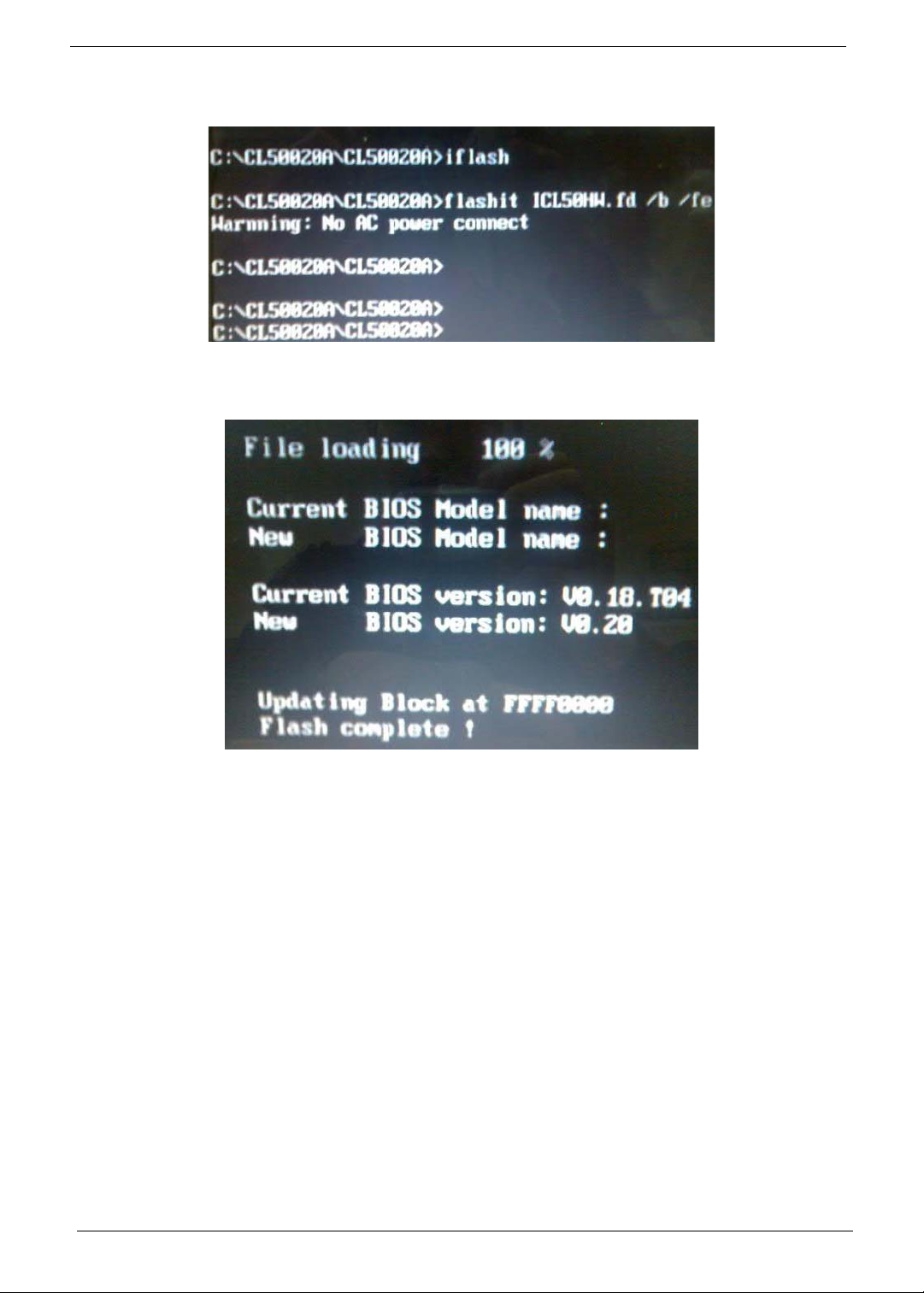
4. In flash BIOS, the message Please do not remove AC Power Source displays.
NOTE: If the AC power is not connected, the following message displays.
Plug in the AC power to continue.
5. Flash is complete when the following message displays.
6. Shutdown or reboot base on iflash.bat command.
36 Chapter 2
Page 47
Remove HDD/BIOS Utility
This section provide you with removing HDD/BIOS method:
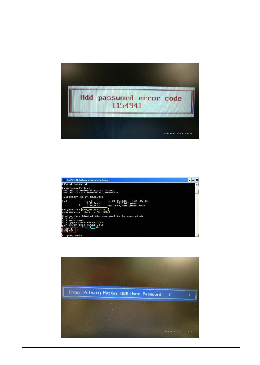
Remove HDD Password:
• If you key in wrong HDD password three times, Hdd password error code displays. See the image
below.
To reset the HDD password, run HDD_PW.EXE as follows:
1.
Key in hdd_pw 15494 0
2. Press 2.
3. Select one upper-case string from the list.
4. Reboot system and key in the selected string (0KJFN42 or UVEIQ96) on the HDD User
Password screen.
Chapter 2 37
Page 48
Remove BIOS Password:
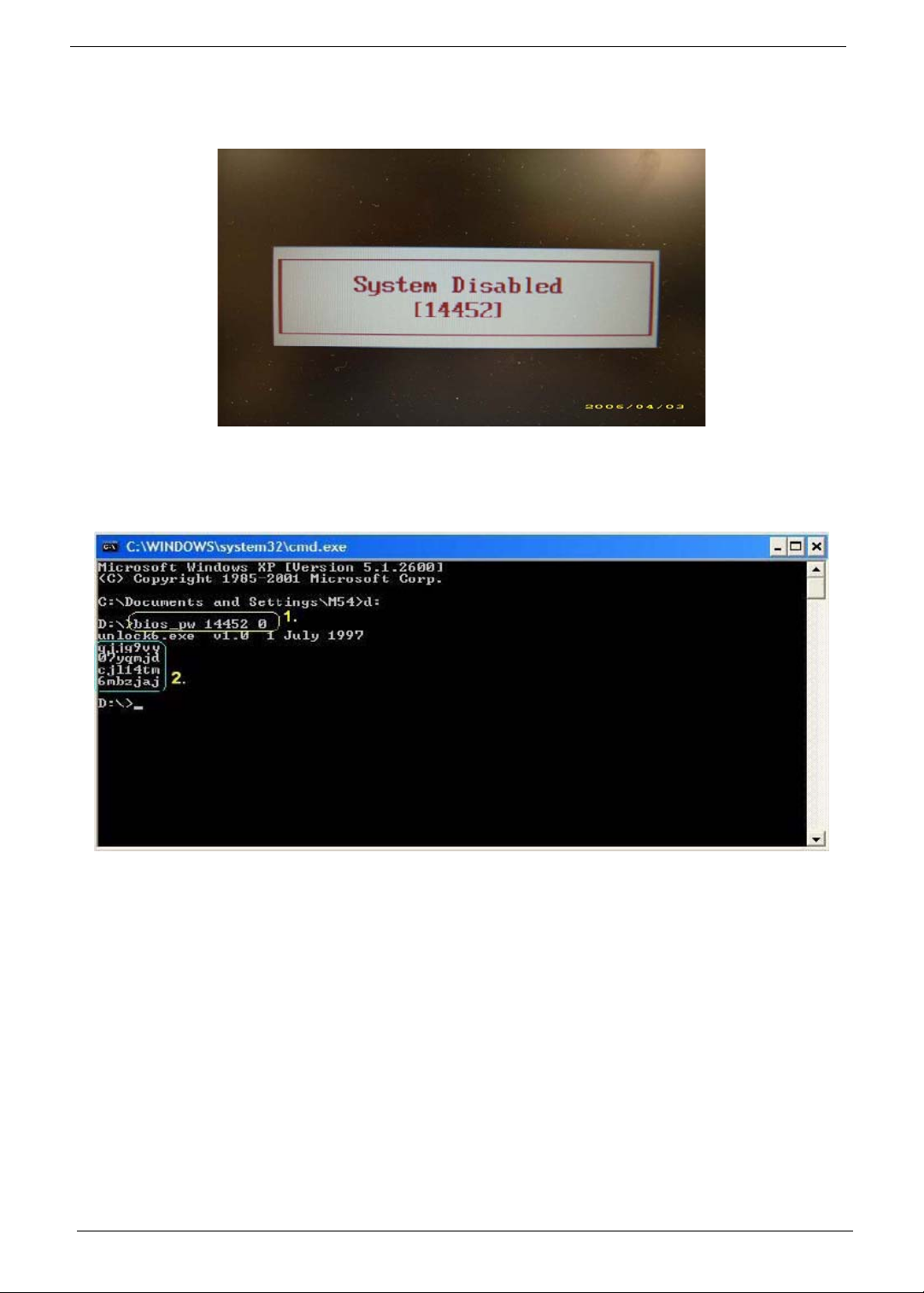
If you key in the wrong Supervisor Password three times, System Disabled displays on the screen. See the
image below.
To reset the BIOS password, run BIOS_PW.EXE as follows:
1.
Key in bios_pw 14452 0
2. Select one string from the list.
38 Chapter 2
Page 49
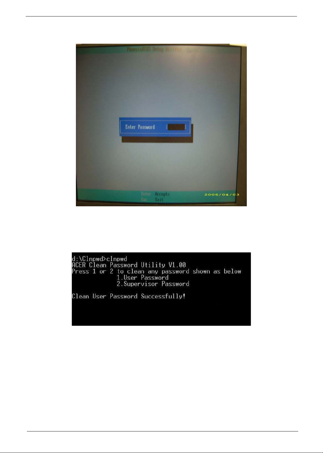
3. Reboot the system and key in the selected string (qjjg9vy, 07yqmjd etc.) for the BIOS user
password.
Removing BIOS Passwords:
To clear the password, perform the following steps:
1. From a DOS prompt, Execute clnpwd.exe
2. Press 1 or 2 to clean the desired password shown on the screen.
The onscreen message determines whether the function is successful or not.
Chapter 2 39
Page 50

40 Chapter 2
Page 51

Chapter 3
Machine Disassembly and Replacement
This chapter contains step-by-step procedures on how to disassemble the notebook computer for
maintenance and troubleshooting.
Disassembly Requirements
To disassemble the computer, you need the following tools:
• Wrist grounding strap and conductive mat for preventing electrostatic discharge
• Flat screwdriver
• Philips screwdriver
• Plastic flat screwdriver
• Plastic tweezers
NOTE: The screws for the different components vary in size. During the disassembly process, group the
screws with the corresponding components to avoid mismatch when putting back the components.
IMPORTANT:Various images depict the use of a regular metal screwdriver, however, a plastic screwdriver is
advised when disassembling parts near or around the motherboard and to prevent scratching of the
computer surface.
Chapter 3 41
Page 52
General Information
Pre-disassembly Instructions
Before proceeding with the disassembly procedure, make sure that you do the following:
1. Turn off the power to the system and all peripherals.
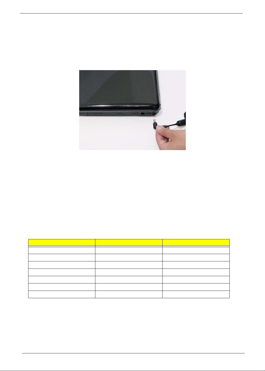
2. Unplug the AC adapter and all power and signal cables from the system.
3. Place the system on a flat, stable surface.
4. Remove the battery pack.
Disassembly Process
The disassembly process is divided into the following stages:
• External module disassembly
• Main unit disassembly
• LCD module disassembly
The flowcharts provided in the succeeding disassembly sections illustrate the entire disassembly sequence.
Observe the order of the sequence to avoid damage to any of the hardware components. For example, if you
want to remove the main board, you must first remove the keyboard, then disassemble the inside assembly
frame in that order.
Main Screw List
Screw Quantity Part Number
M2.5*8 (NL) 15 86.AR102.001
M2.5*5 (NL) 22 86.AR102.002
M2*3 (NL) 36 86.AR102.004
M2*6 (NL) 4 86.AR102.007
M2*4-NI (NL) 5 86.AR102.006
M3*3 (NL) 4 86.AR102.009
M2.5*6.5 4 86.AR102.012
42 Chapter 3
Page 53
External Module Disassembly Process
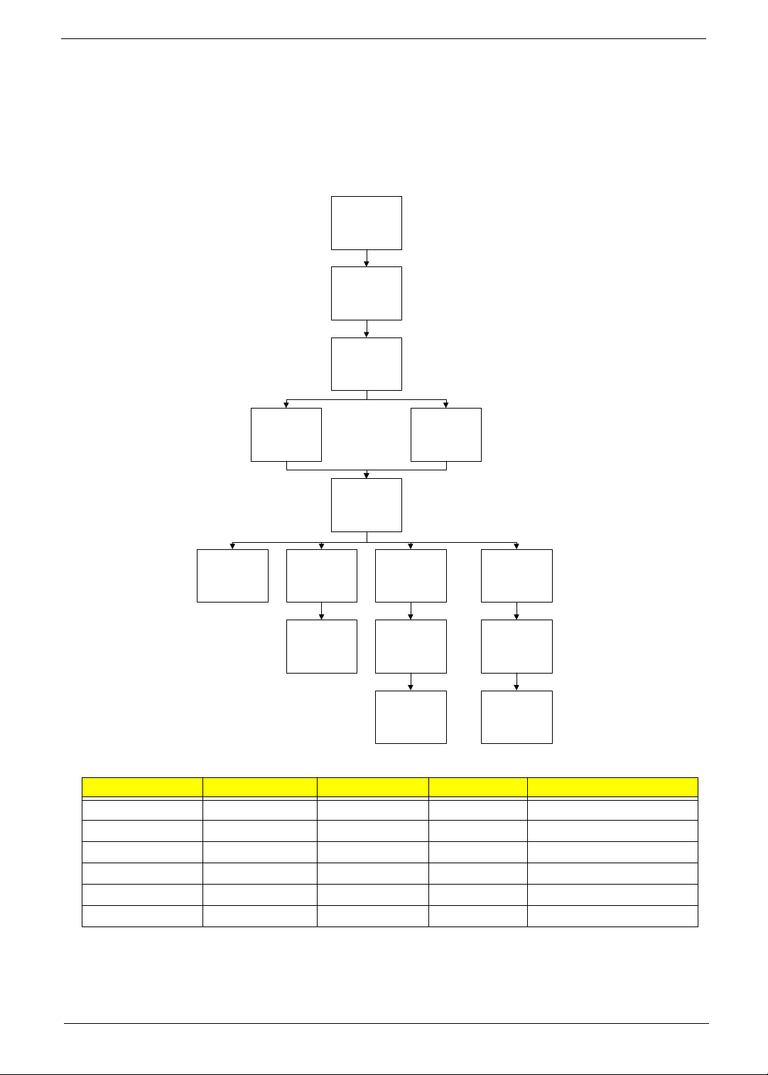
External Modules Disassembly Flowchart
The flowchart below gives you a graphic representation on the entire disassembly sequence and instructs you
on the components that need to be removed during servicing. For example, if you want to remove the main
board, you must first remove the keyboard, then disassemble the inside assembly frame in that order.
Turn off sys tem
and peripheral s
power
Disconnect power
and signal cables
from system
Remove Battery
Express Dummy
Remove
Remove
Remove
HDD
Remove
Card
Remove
ODD Module
Remove
ODD
Remove
ODD Bracket
Remove
DIMM Modul es
Remove
SD Dummy Card
WLAN Antenna
WLAN Board
Remove
Remove
Remove
Lower Covers
HDD Module
HDD Bracket
Screw List
Step Screw Quantity Color Part No.
Memory Cover M2.5*8 (NL) 2 Black 86.AR102.001
WLAN Cover M2.5*8 (NL) 1 Black 86.AR102.001
WLAN Module M2*3 (NL) 2 Black 86.AR102.004
HDD Carrier M3*3 (NL) 4 Silver 86.AR102.009
ODD Module M2.5*5(NL) 1 Black 86.AR102.002
ODD Bracket M2*3 (NL) 3 Black 86.AR102.004
Chapter 3 43
Page 54
Removing the Battery Pack
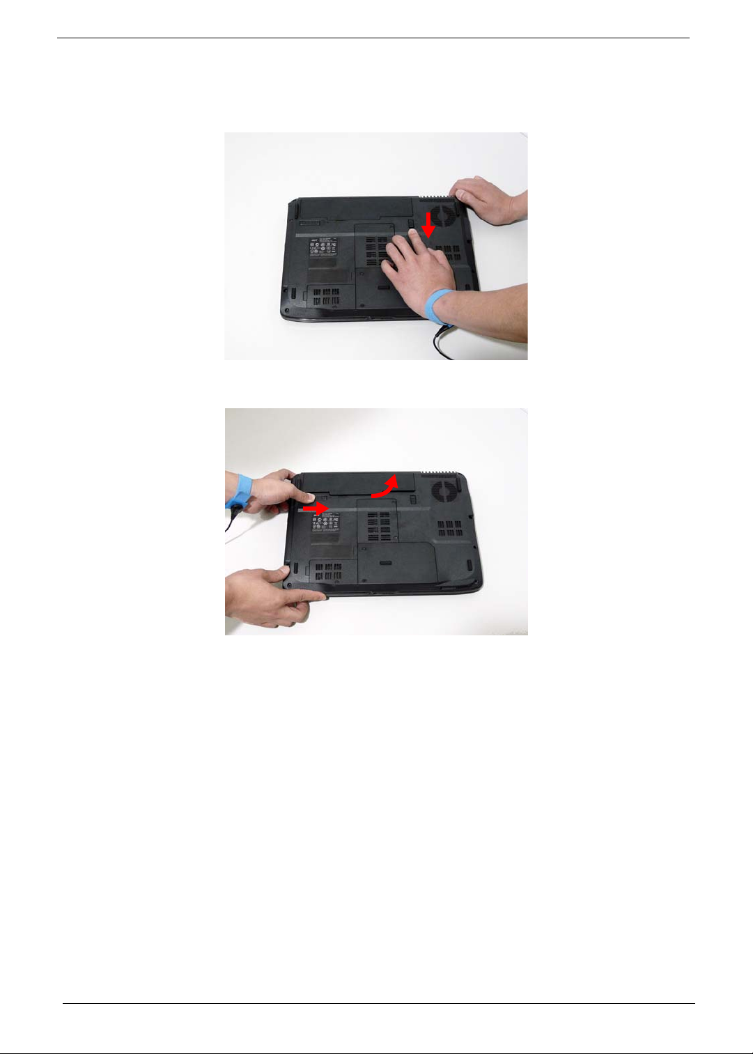
1. Turn computer over.
2. Slide the battery lock/unlock latch to the unlock position.
3. Slide and hold the battery release latch to the release position (1), then slide out the battery pack from the main
unit (2).
2
1
44 Chapter 3
Page 55
Removing the SD dummy card
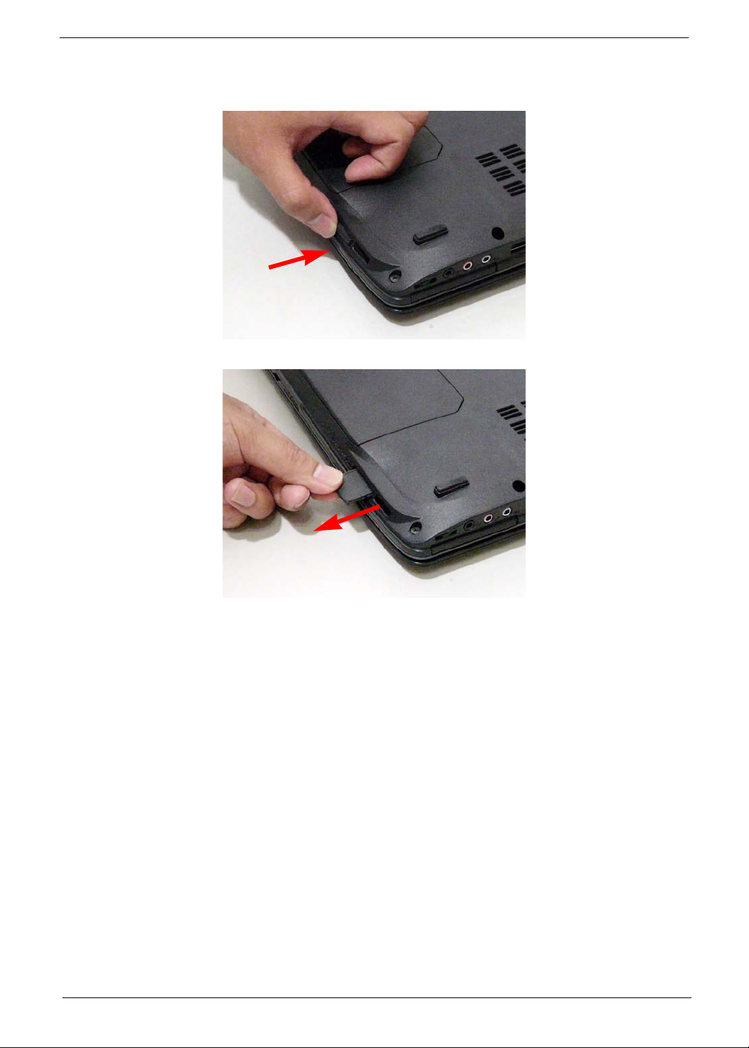
1. Push the SD dummy card all the way in to eject it.
2. Pull it out from the slot.
Chapter 3 45
Page 56
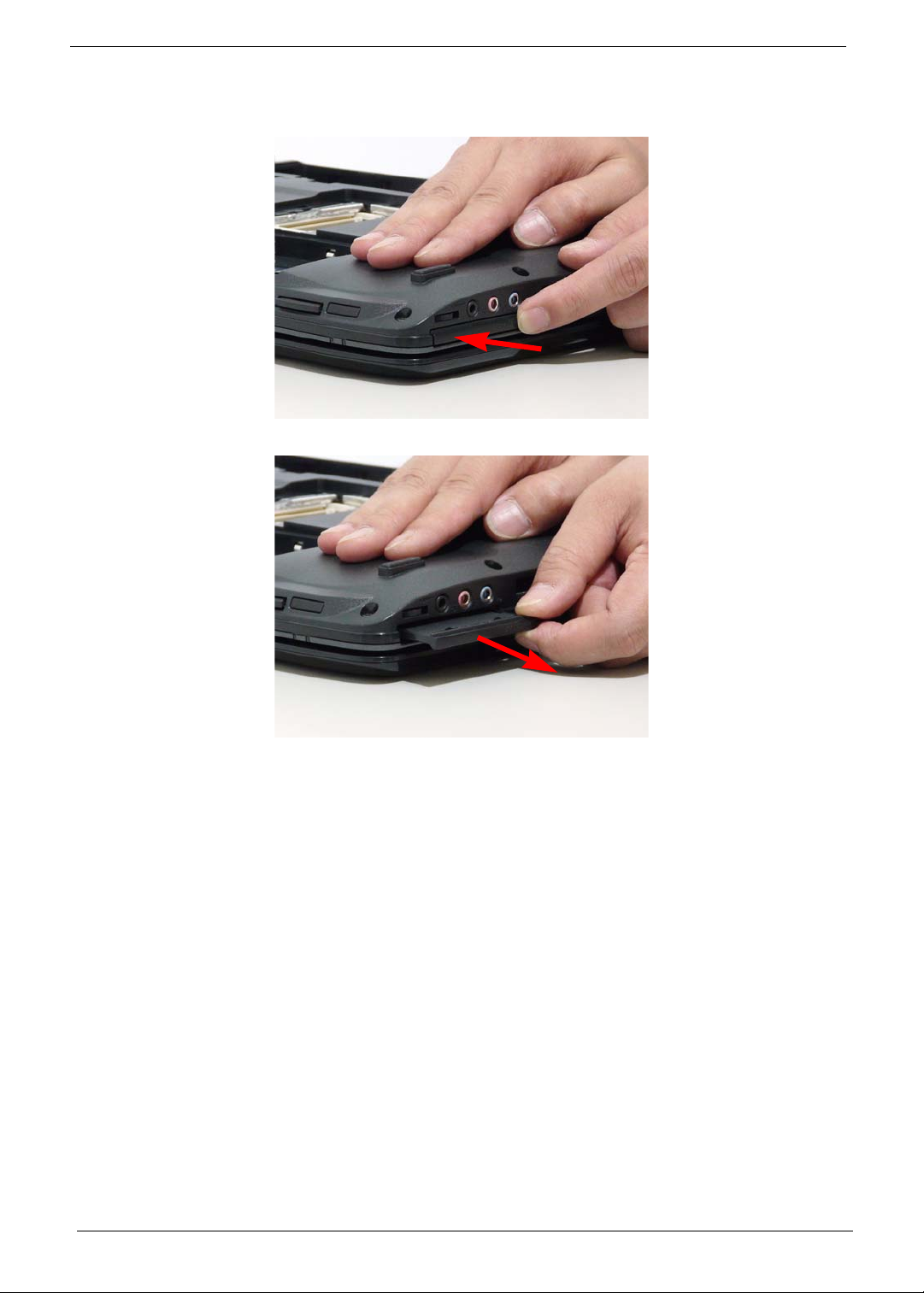
Removing the ExpressCard dummy card
1. Push the ExpressCard dummy card all the way in to eject it.
2. Pull it out from the slot.
46 Chapter 3
Page 57
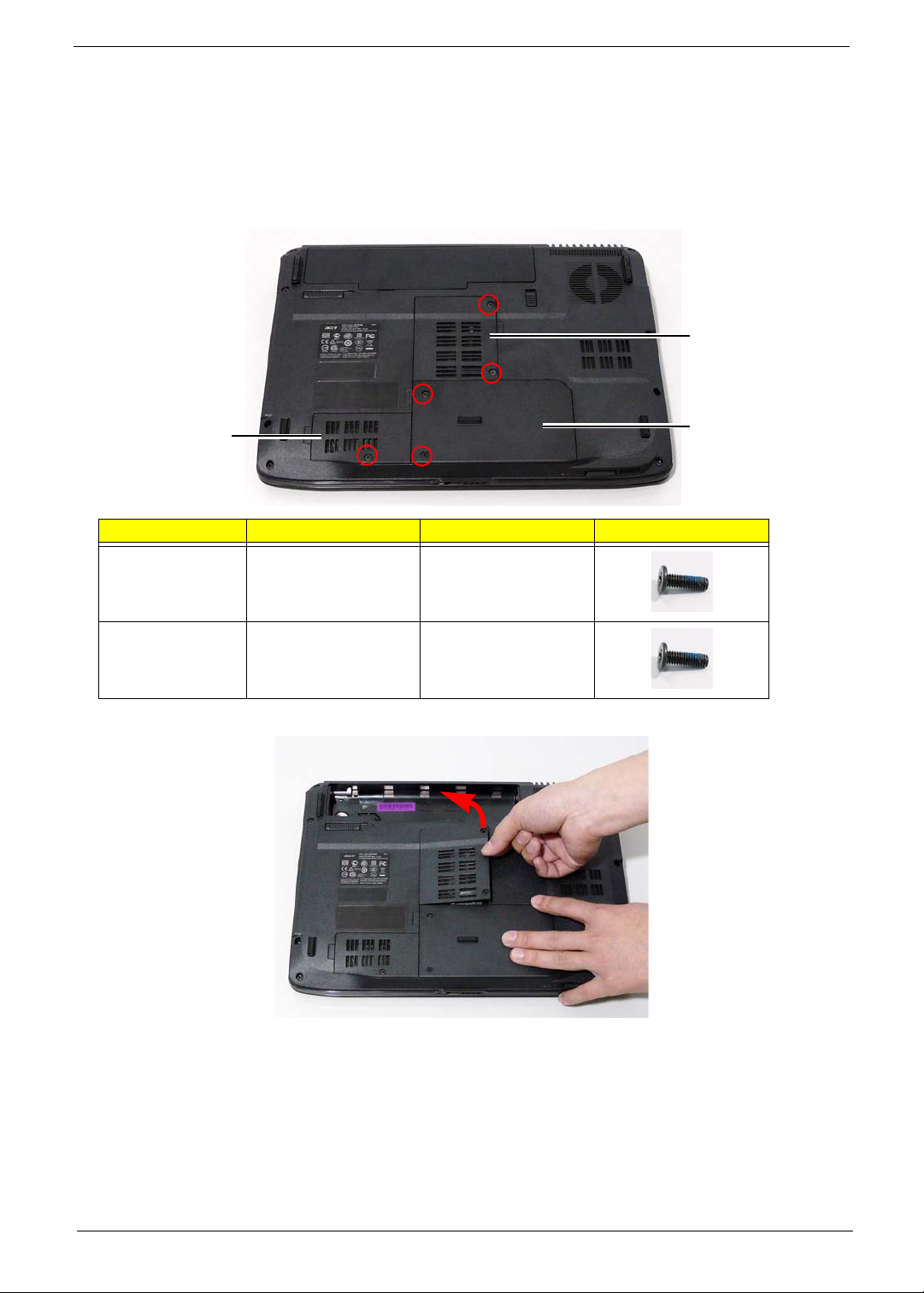
Removing the Lower Covers
1. See “Removing the Battery Pack” on page 44.
2. See “Removing the SD dummy card” on page 45.
3. See “Removing the ExpressCard dummy card” on page 46.
4. Remove the three screws from the memory and WLAN bays and loosen the two captive screws on the HDD
cover.
Memory
Cover
WLAN
Cover
Step Size Quantity Screw Type
Memory Cover M2.5*8 (NL) 2
WLAN Cover M2.5*8 (NL) 1
5. Carefully open the memory cover.
HDD
Cover
Chapter 3 47
Page 58
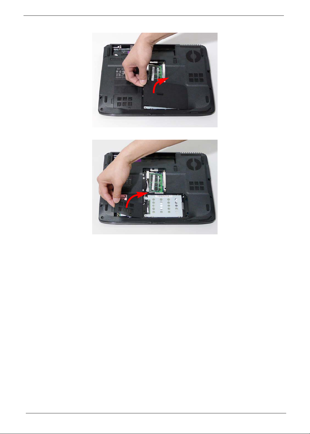
6. Remove the HDD cover as shown.
7. Remove the WLAN cover as shown.
48 Chapter 3
Page 59
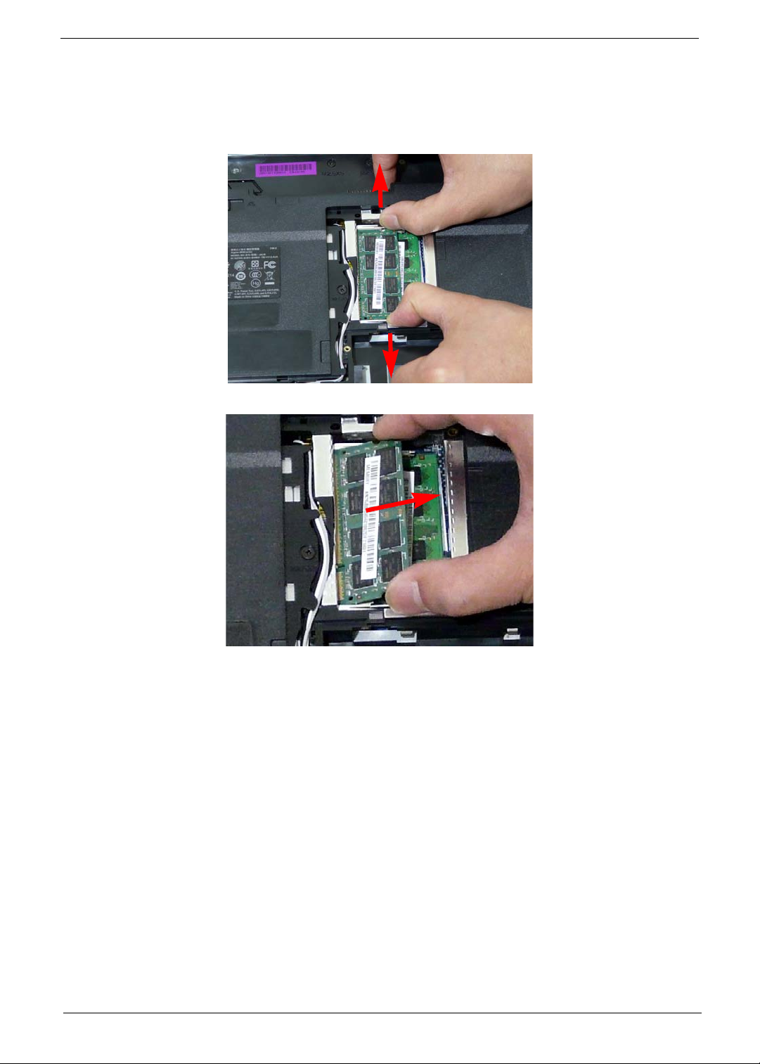
Removing the DIMM Modules
1. See “Removing the Battery Pack” on page 44.
2. Remove the Memory Module cover See “Removing the Lower Covers” on page 47.
3. Push out the release latches on both sides of the DIMM socket to release the DIMM module.
4. Remove the DIMM module.
5. Repeat steps for the second DIMM module if present.
Chapter 3 49
Page 60
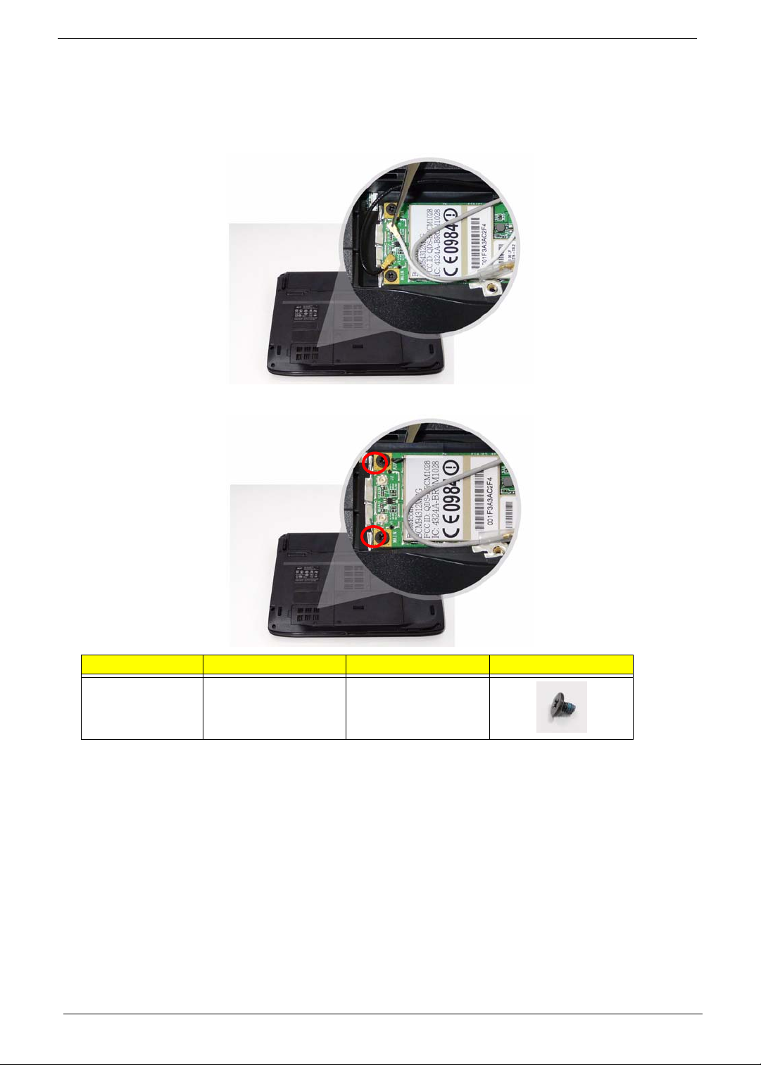
Removing the WLAN Module
1. See “Removing the Battery Pack” on page 44.
2. Remove the WLAN cover. See “Removing the Lower Covers” on page 47.
3. Disconnect the antenna cables from the WLAN board.
4. Move the antenna away and remove the two screws on the WLAN board to release the WLAN board.
Step Size Quantity Screw Type
WLAN Module M2*3 (NL) 2
50 Chapter 3
Page 61
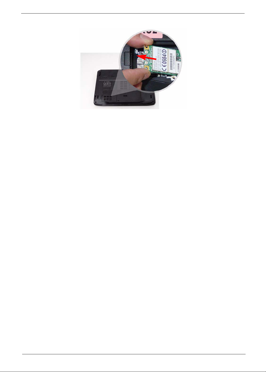
5. Detach the WLAN board from the WLAN socket.
NOTE: When attaching the antenna back to the WLAN board, make sure the cables are sitting in the housing
to prevent damage.
Chapter 3 51
Page 62
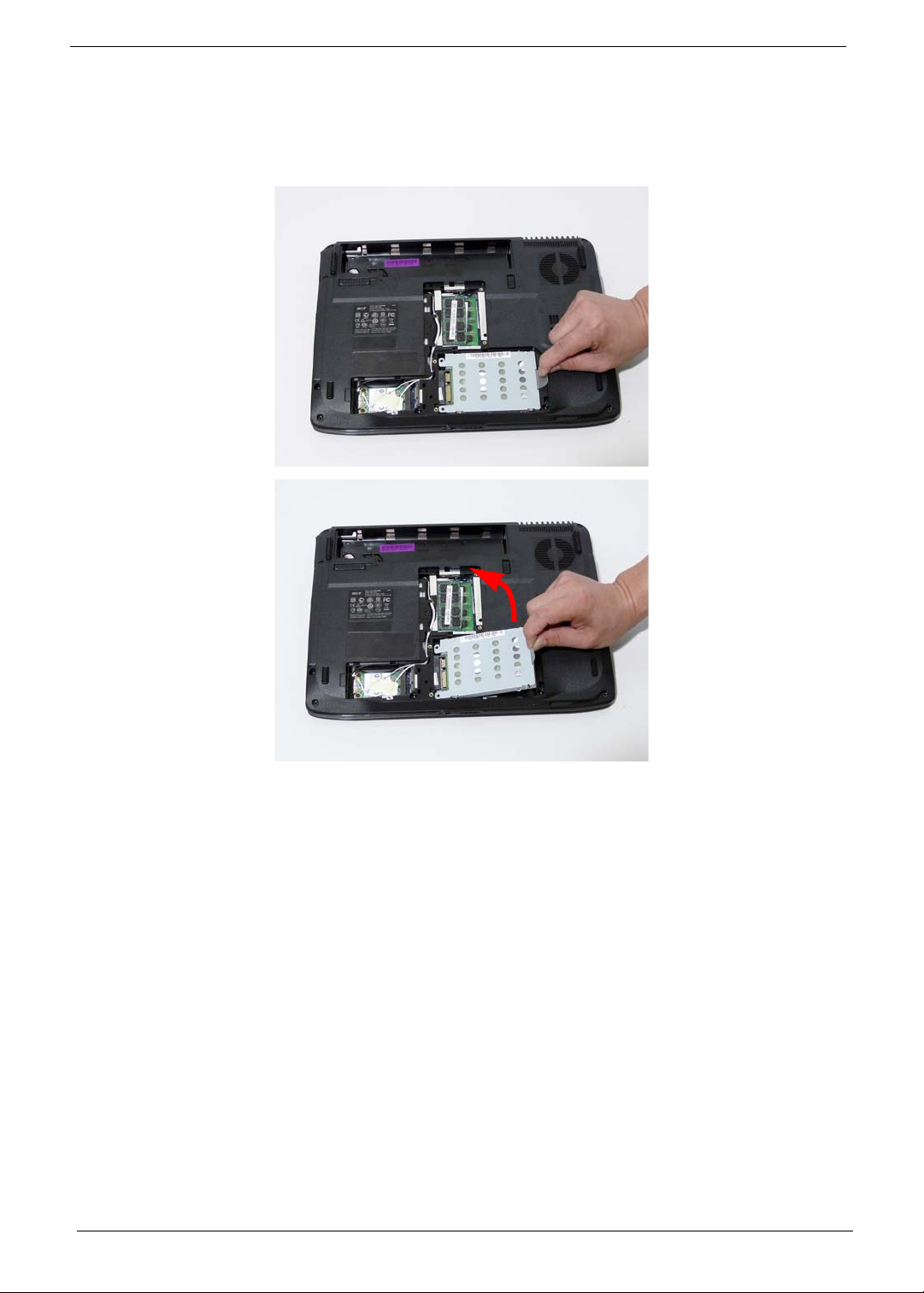
Removing the Hard Disk Drive Module
1. See “Removing the Battery Pack” on page 44.
2. Remove the HDD cover, See “Removing the Lower Covers” on page 47.
3. Use the pull-tab to pull and lift the hard disk drive module out of the bay.
NOTE: To prevent damage to device, avoid pressing down on it or placing heavy objects on top of it.
52 Chapter 3
Page 63
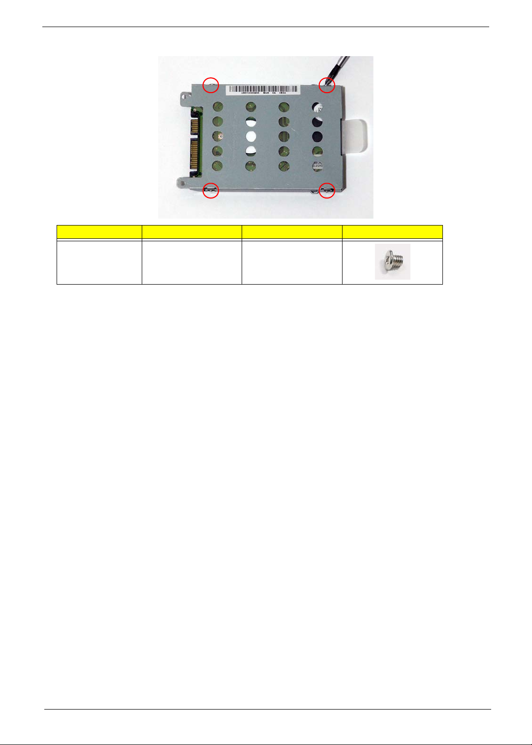
4. Remove the four screws securing the hard disk to the carrier.
Step Size Quantity Screw Type
HDD Carrier M3*3 (NL) 4
Chapter 3 53
Page 64
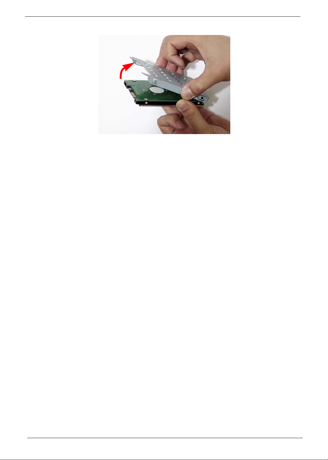
5. Remove the HDD from the carrier.
54 Chapter 3
Page 65
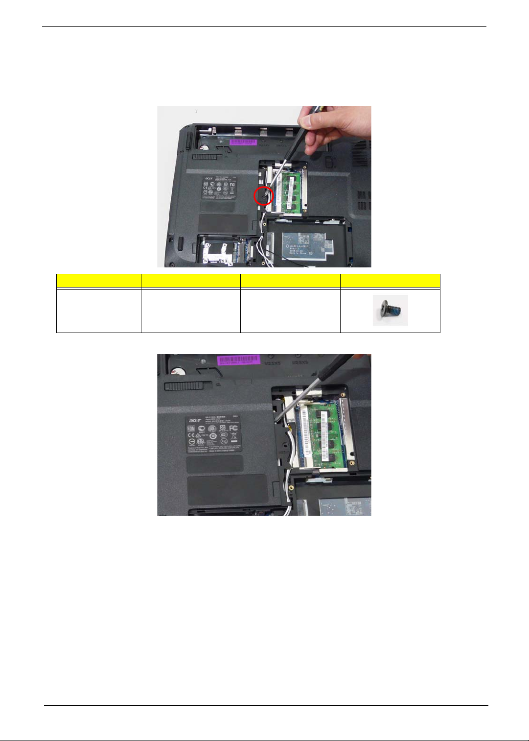
Removing the Optical Drive Module
1. See “Removing the Battery Pack” on page 44.
2. Remove the Memory cover. See “Removing the Lower Covers” on page 47.
3. Remove the screw securing the ODD module.
Step Size Quantity Screw Type
ODD Module M2.5*5(NL) 1
4. Carefully insert a screw driver to release the locking latch.
NOTE: A plastic screw driver is recommended to prevent scratching the surface of the computer.
Chapter 3 55
Page 66
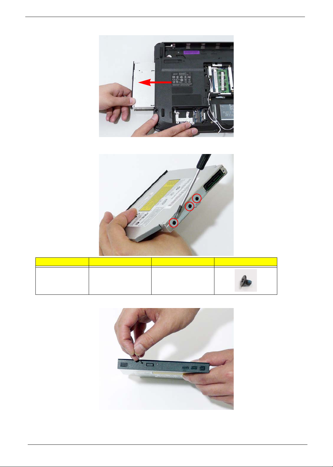
5. Pull the optical drive module out from the chassis.
6. Remove the three screws securing the ODD bracket and remove the ODD bracket from the optical disk drive
module.
Step Size Quantity Screw Type
ODD Bracket M2*3 (NL) 3
7. Insert a pin in the eject hole of the ODD to eject the ODD tray.
56 Chapter 3
Page 67
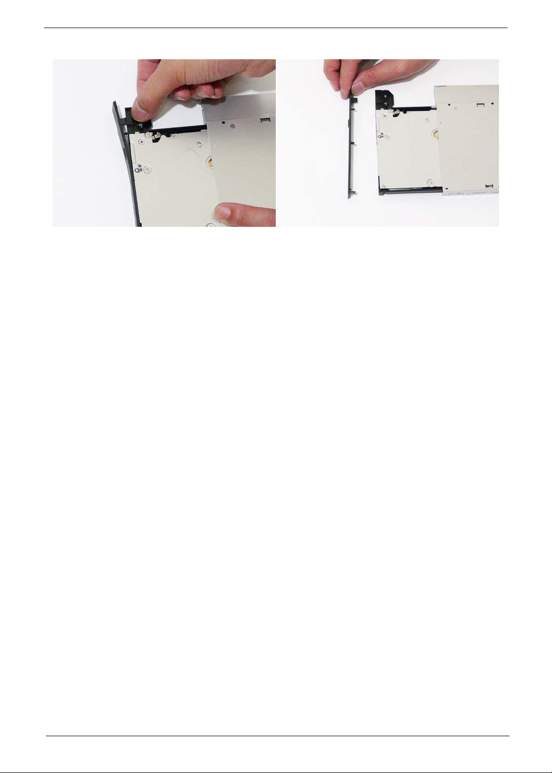
8. Press down on the locking catch to release the ODD cover and remove.
Chapter 3 57
Page 68
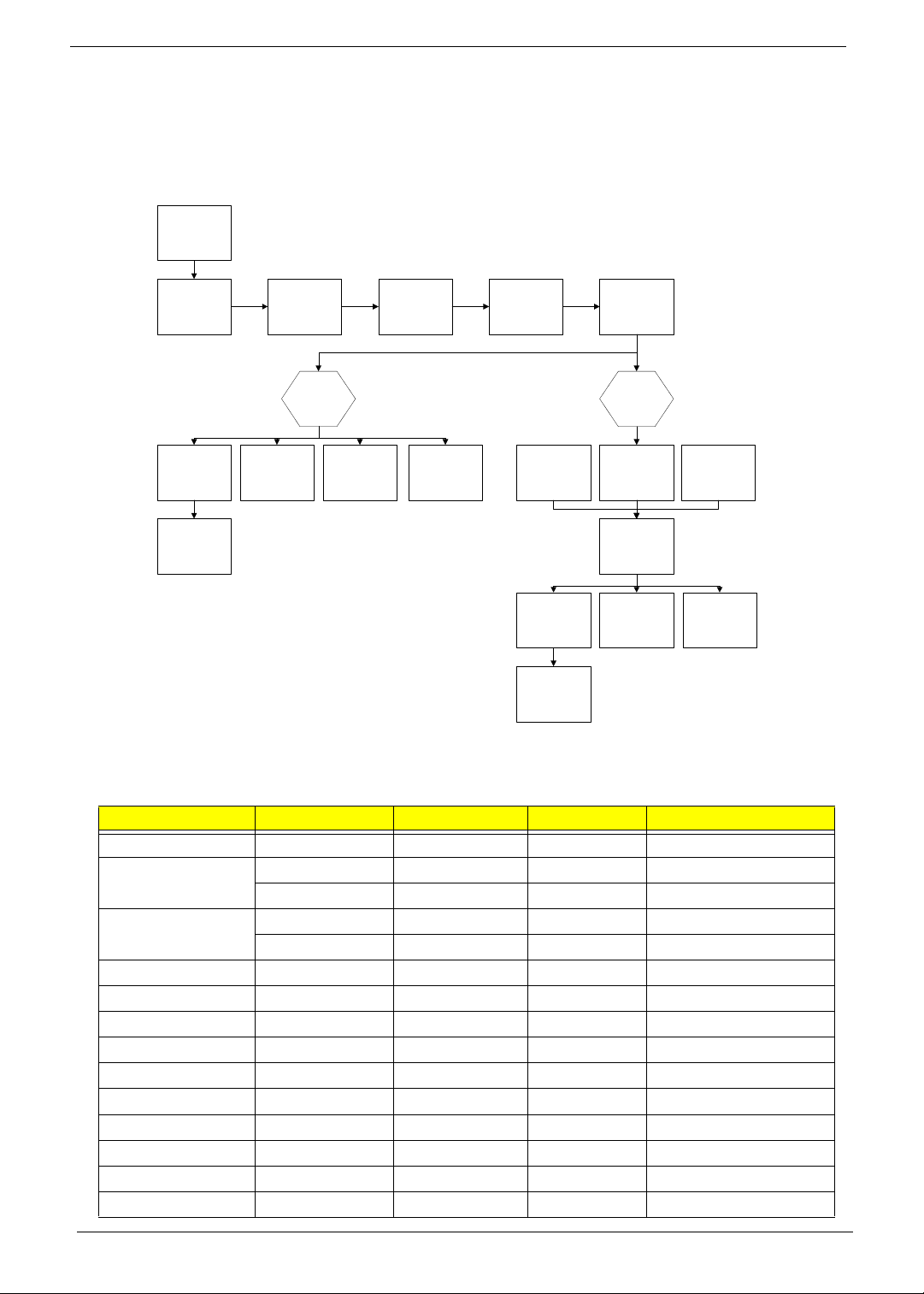
Main Unit Disassembly Process
Main Unit Disassembly Flowchart
Remove External
Modules before
proceeding
Remove
Switch Cover
Remove
Touchpad
Bracket
Remove
Finger Print
Reader
Remove
Keyboard
Remove
Launch Board
Upper
Cover
Speaker Module
Remove
Remove
Antenna
Remove
Switch Board
Remove
LCD Module
I/O Board
Thermal Module
Remove
Remove
Remove
CPU
Remove
Upper Cover
Lower
Cover
Remove
Bluetooth Board
Remove
Mainboard
Remove
CPU Fan
Remove
Modem Board
Remove
HDMI Module
Screw List
Step Screw Quantity Color Part No.
Switch Cover M2*3 (NL) 2 Black 86.AR102.004
LCD Module M2.5*8(NL) 4 Black 86.AR102.001
M2.5*5 (NL) 2 Black 86.AR102.002
Upper Cover M2.5*8 (NL) 8 Black 86.AR102.001
M2.5*5 (NL) 7 Black 86.AR102.002
Touch Pad Bracket M2*3 (NL) 2 Black 86.AR102.004
Launch Board M2*3 (NL) 2 Black 8 6.AR102.004
Speaker M2*3 (NL) 4 Black 86.AR102.004
I/O Board M2.5*5 (NL) 1 Black 86.AR102.002
Bluetooth Board M2*3 (NL) 1 Black 86.AR102.004
Modem Module M2*3 (NL) 2 Black 86.AR102.004
Mainboard M2.5*5 (NL) 1 Black 86.AR102.002
Thermal Module M2.5*6.5 4 Black 86.AR102.012
CPU Fan M2*4-NI (NL) 3 Black 86.AR102.006
HDMI Module M2*4-NI (NL) 2 Black 86.AR102.006
58 Chapter 3
Page 69
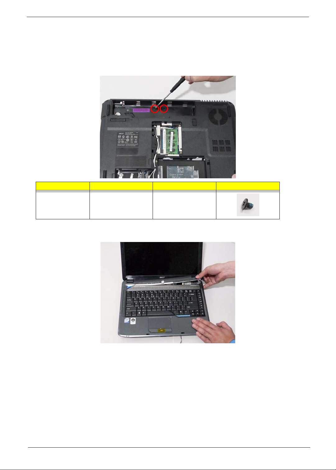
Removing the Switch Cover
CAUTION: Using tools to remove the Switch Cover may cause damage to the outer casing. It is
recommended that you only use your fingers to remove the Switch Cover.
1. See “Removing the Battery Pack” on page 44.
2. Locate and remove the two securing screws as shown.
Step Size Quantity Screw Type
Switch Cover M2*3(NL) 2
3. Turn the computer over and open the LCD module to expose the Switch Cover.
4. Lift the Switch Cover as shown, and move from right to left side.
Chapter 3 59
Page 70
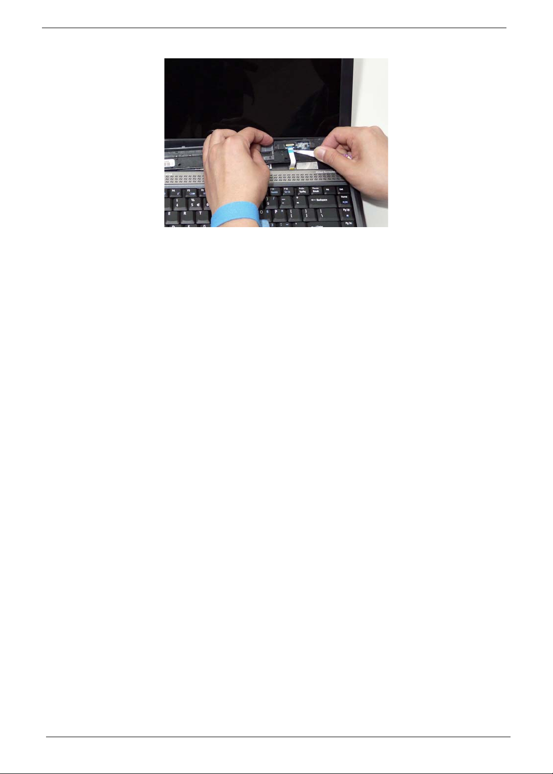
5. Turn the Switch Cover over to expose the FFC cable and detach it using the tweezers.
6. Lift the Switch Cover clear of the chassis.
60 Chapter 3
Page 71
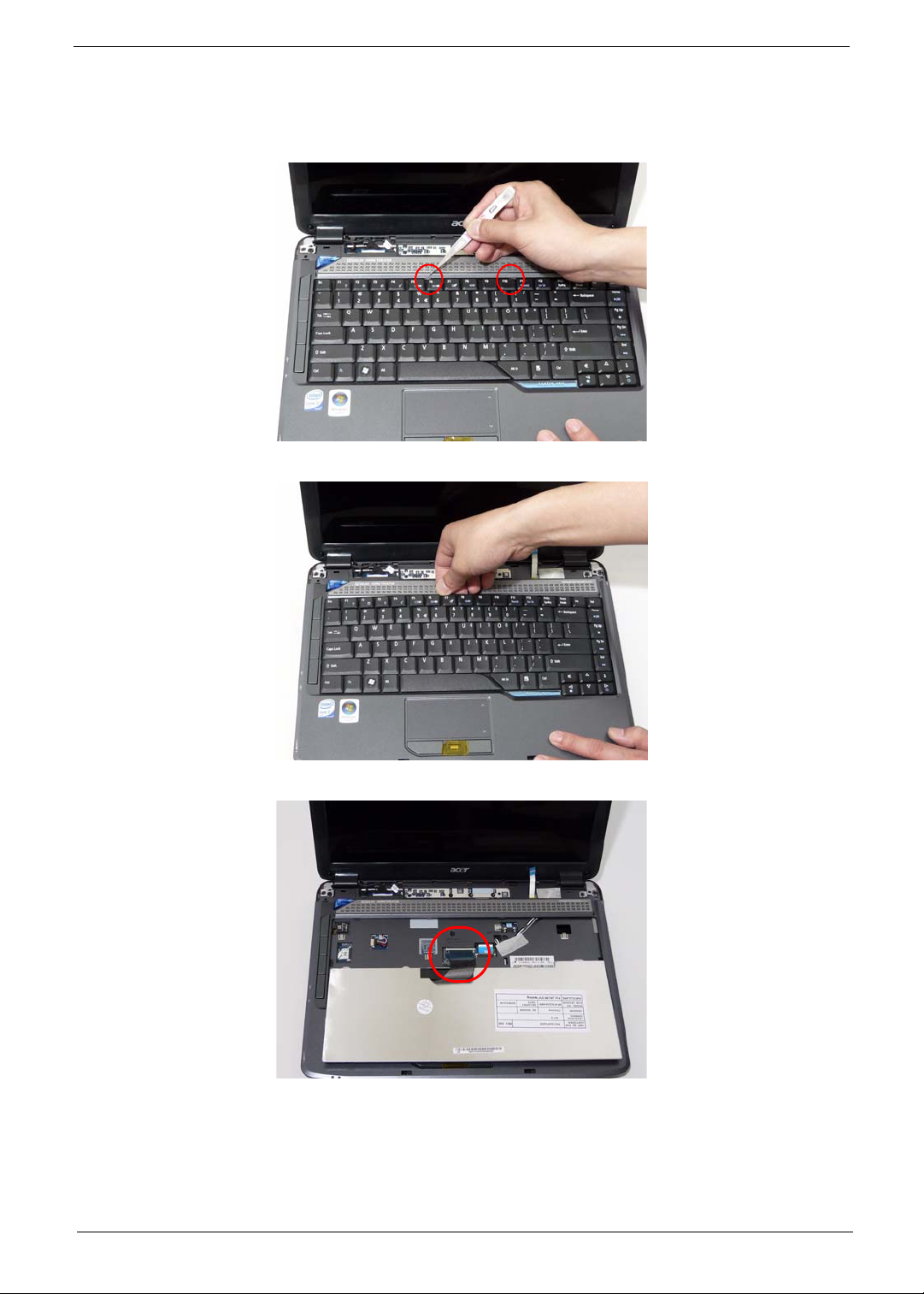
Removing the Keyboard
1. See “Removing the Battery Pack” on page 44.
2. Using a plastic pry, push in the two securing latches and slide the pry under the keyboard.
3. Once both latches are released, lift the keyboard away from the chassis as shown.
4. Turn the keyboard over on the Touch Pad area to expose the FFC cable.
Chapter 3 61
Page 72
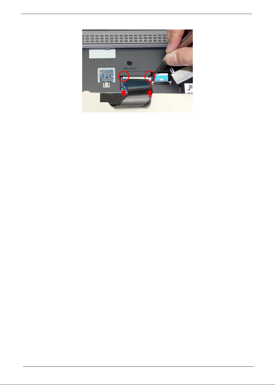
5. Using a pry, pull both sides of the retainer to disconnect the FFC cable from the mainboard.
62 Chapter 3
Page 73
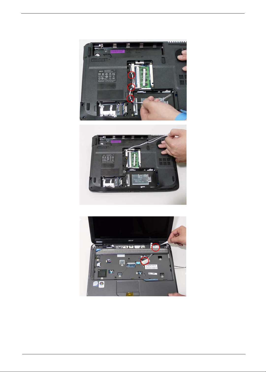
Removing the Antenna
1. Remove the Antenna Cables from the securing pins as shown.
2. Turn the computer over. Remove the adhesive strips holding the antenna cables.
Chapter 3 63
Page 74
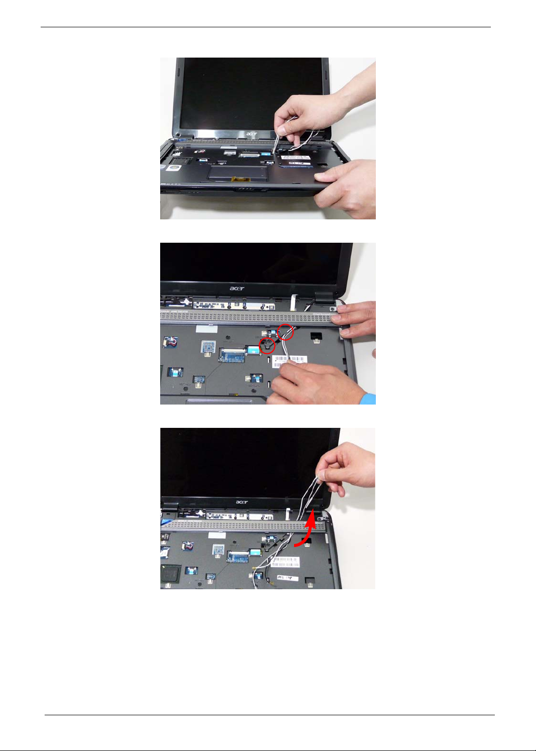
3. Feed the antenna cables from the underside of the computer.
4. Remove the Antenna Cables from the securing pins as shown.
5. Pull the cables through the speaker panel as shown.
64 Chapter 3
Page 75
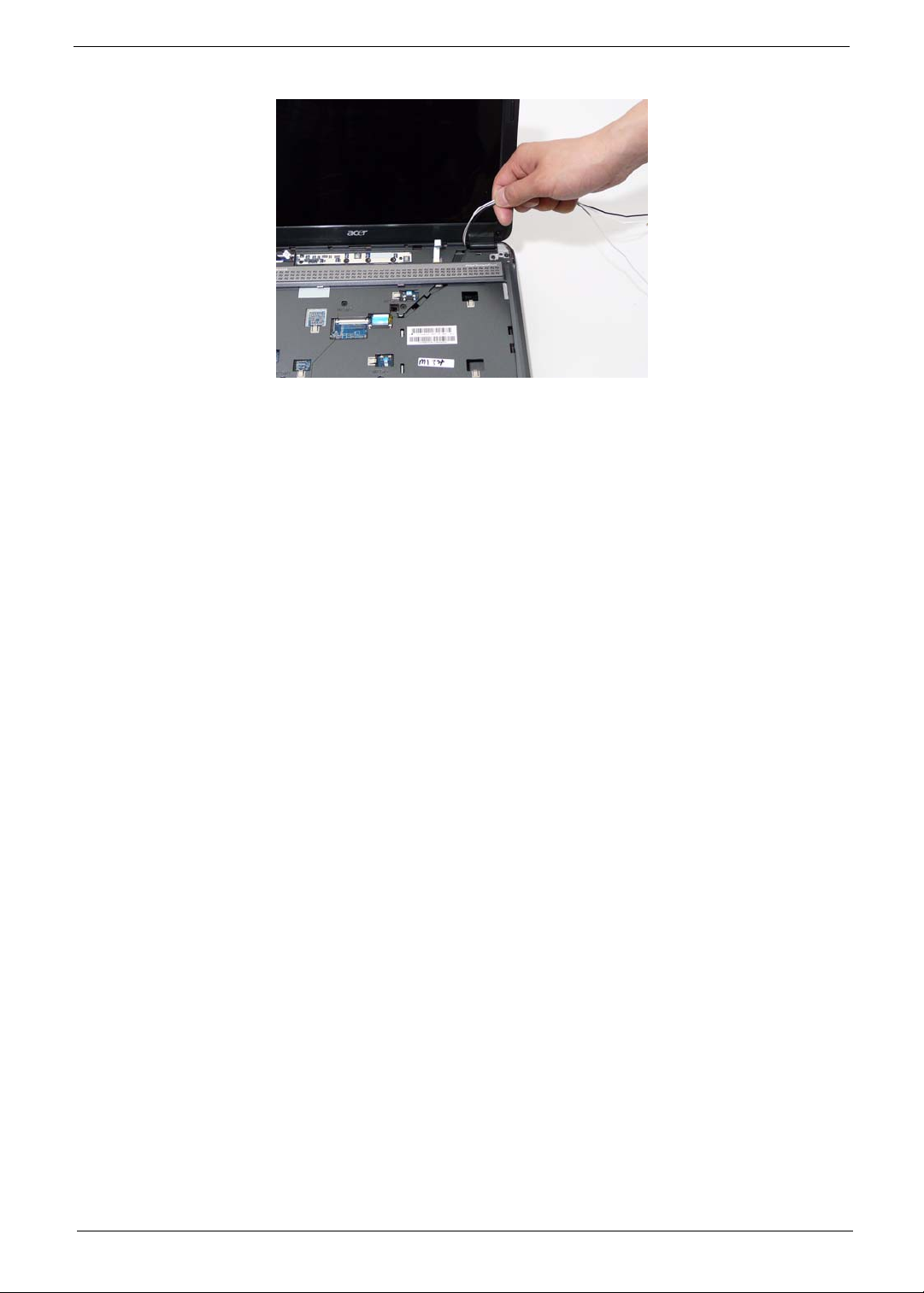
6. Fully remove the antenna cables and move them out of the way to prevent damage.
Chapter 3 65
Page 76
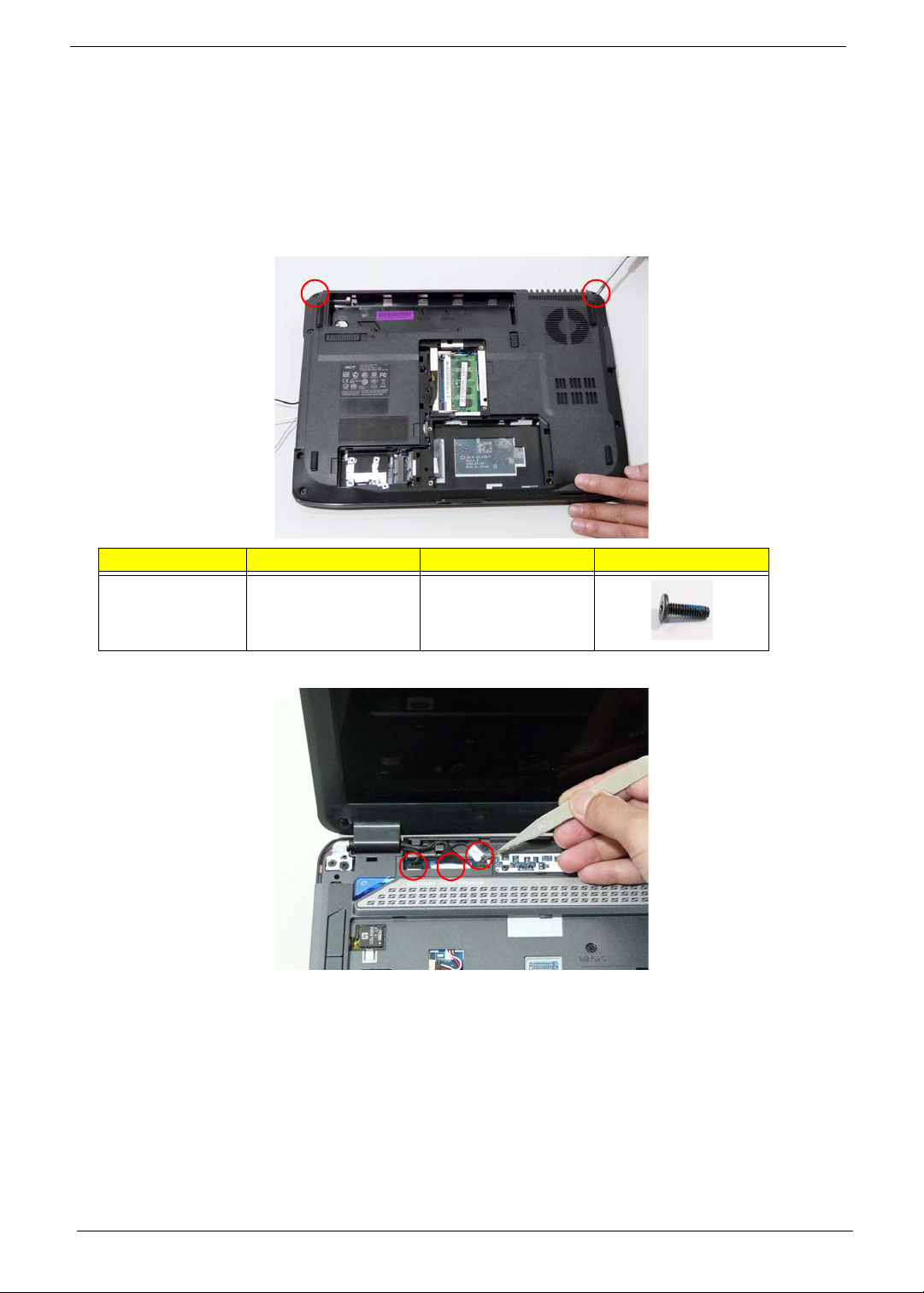
Removing the LCD Module
1. See “Removing the Battery Pack” on page 44.
2. See “Removing the Lower Covers” on page 47.
3. See “Removing the WLAN Module” on page 50.
4. See “Removing the Keyboard” on page 61.
5. See “Removing the Antenna” on page 63.
6. Remove the two securing screws from the bottom of the chassis.
Step Size Quantity Screw Type
LCD Module M2.5*8(NL) 2
7. Turn the computer over. Disconnect the three LCD interface cables from the chassis.
66 Chapter 3
Page 77
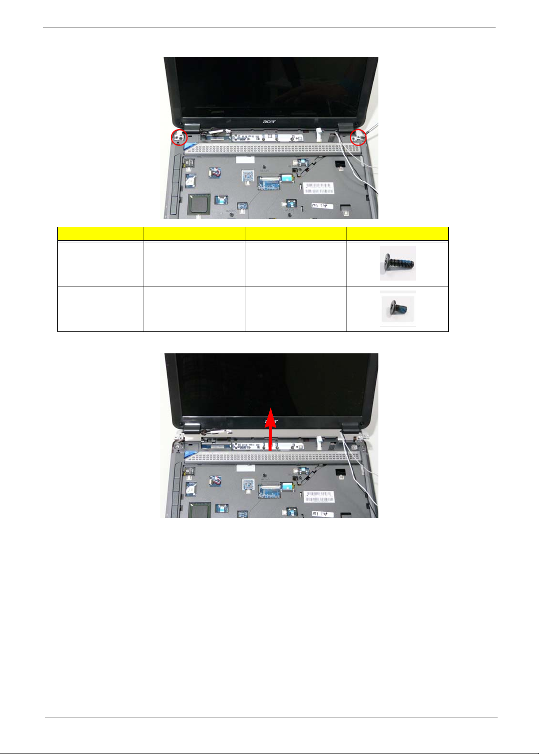
8. Remove the four securing screws (two each side) from the LCD module.
Step Size Quantity Screw Type
LCD Module M2.5*8 (NL) 2
LCD Module M2.5*5 (NL) 2
9. Carefully remove the LCD module from the chassis.
Chapter 3 67
Page 78
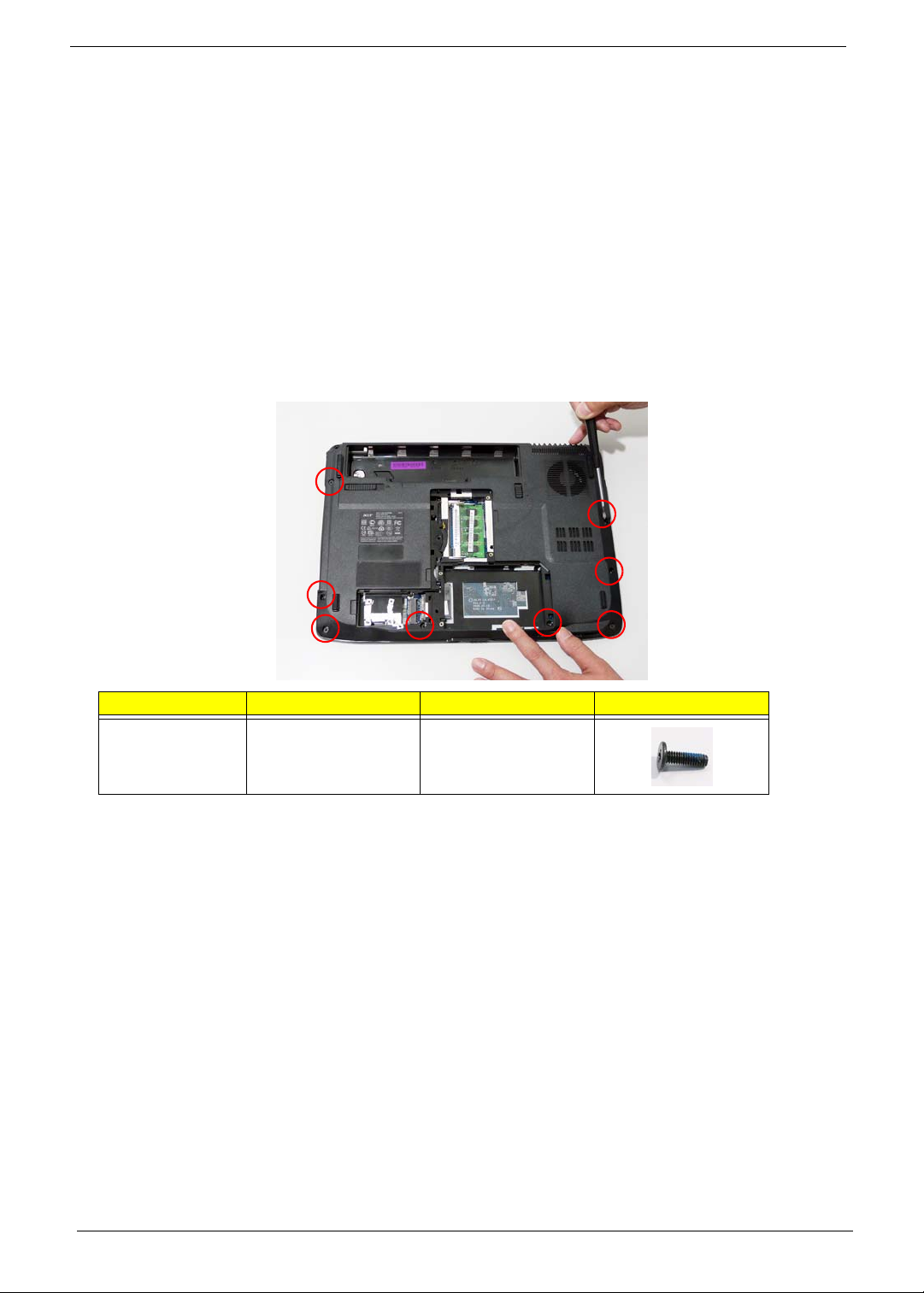
Removing the Upper Cover
1. See “Removing the Battery Pack” on page 44.
2. See “Removing the SD dummy card” on page 45.
3. See “Removing the ExpressCard dummy card” on page 46.
4. See “Removing the Lower Covers” on page 47.
5. See “Removing the DIMM Modules” on page 49.
6. See “Removing the WLAN Module” on page 50.
7. See “Removing the Hard Disk Drive Module” on page 52.
8. See “Removing the Optical Drive Module” on page 55.
9. See “Removing the Switch Cover” on page 59.
10. See “Removing th e Keyboard” on page 61.
11. See “Removing the LCD Module” on page 66.
12. Turn the computer over. Remove the eight screws on the bottom panel.
Step Size Quantity Screw Type
Upper Cover M2.5*8 (NL) 8
68 Chapter 3
Page 79
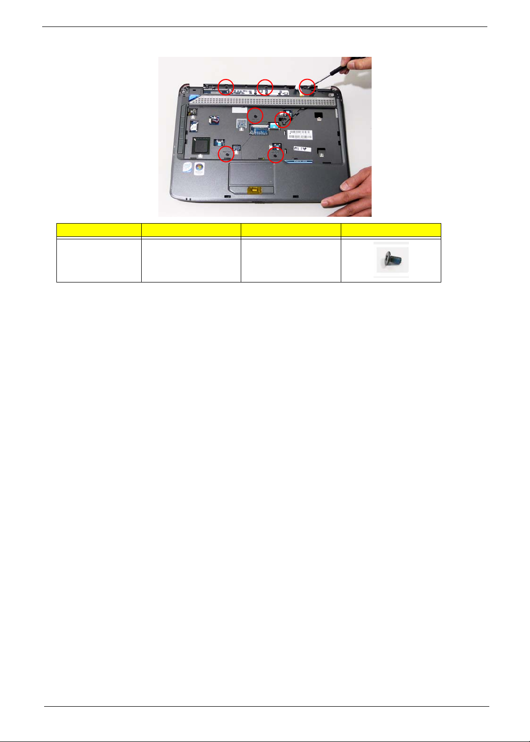
13. Turn the computer over. Remove the seven screws on the top panel.
Step Size Quantity Screw Type
Upper Cover M2.5*5 (NL) 7
Chapter 3 69
Page 80
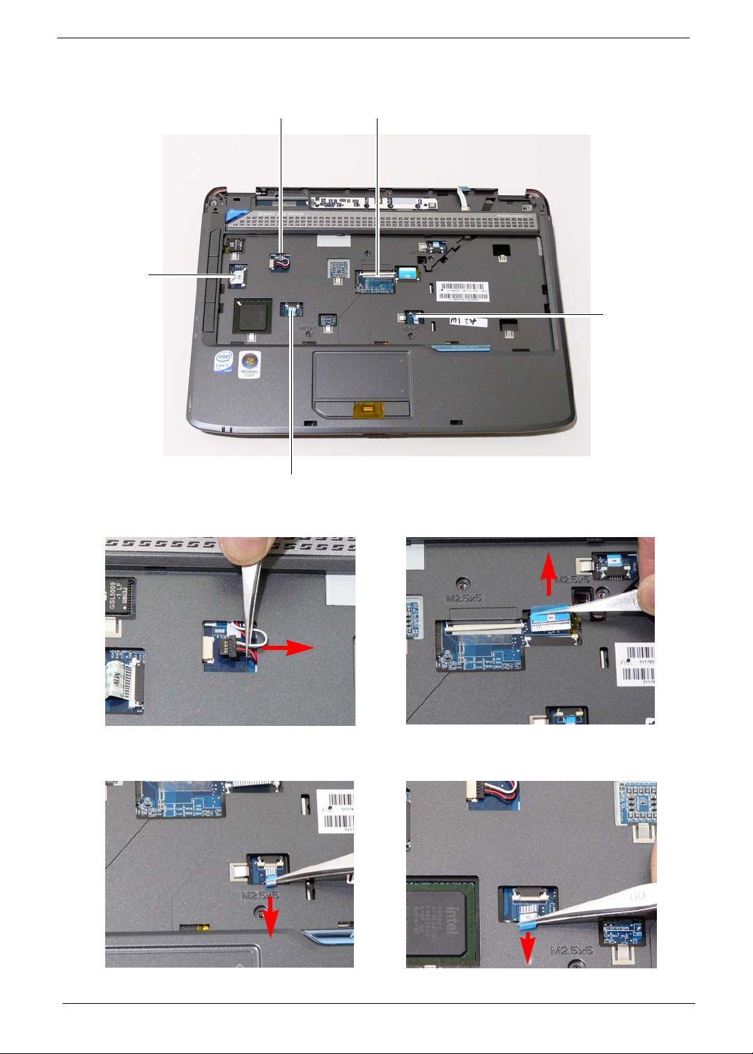
14. Disconnect the five cables from the mainbo ard as shown.
A
E
D
B
C
Disconnect A as shown. Release the securing latches and disconnect B as
shown.
Release the securing latches and disconnect C as
shown.
Release the securing latches and disconnect D as
shown.
70 Chapter 3
Page 81
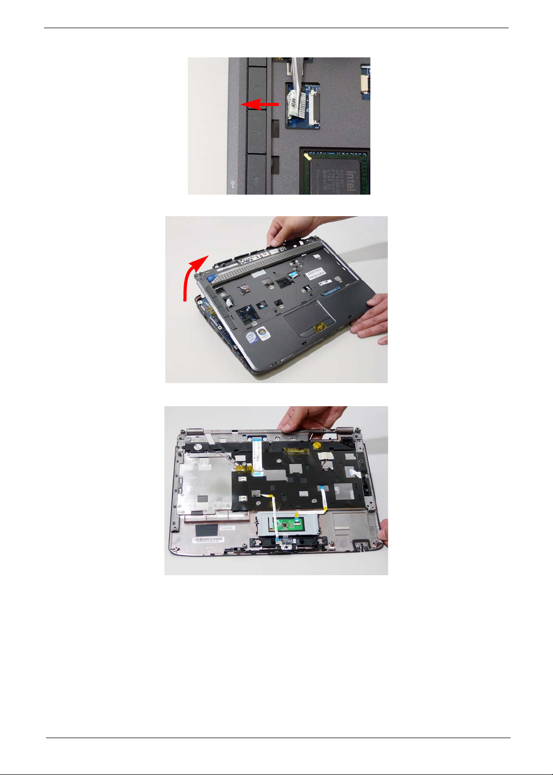
Release the securing latches and disconnect E as shown.
15. Remove the upper cover by lifting upward from the chassis, rear edge first.
16. Turn the upper cover over. The upper cover appears as follows.
NOTE: Avoid pulling on the cables directly to prevent damage to the connectors.
NOTE: Use the pull-tabs on the FFC cables whenever available to prevent damage to the FFC cables.
Chapter 3 71
Page 82
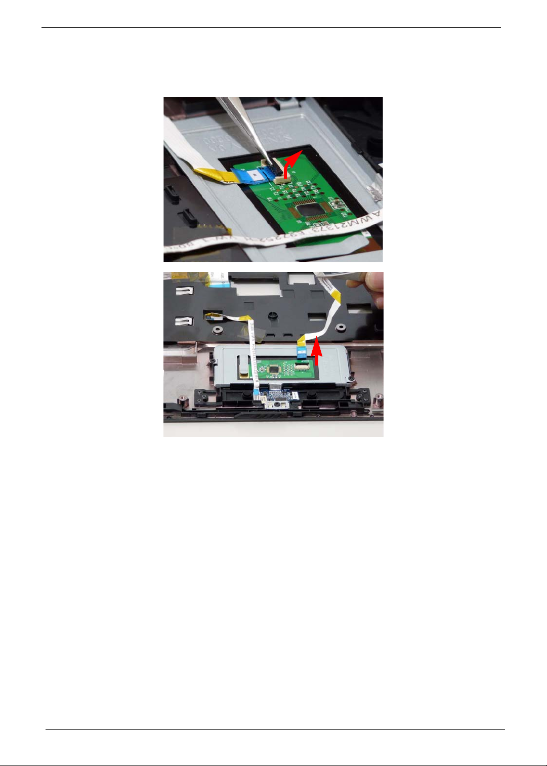
Removing the Touch Pad Bracket
1. See “Removing the Upper Cover” on page 68.
2. Disconnect the Touch Pad cable from the Touch Pad board.
72 Chapter 3
Page 83
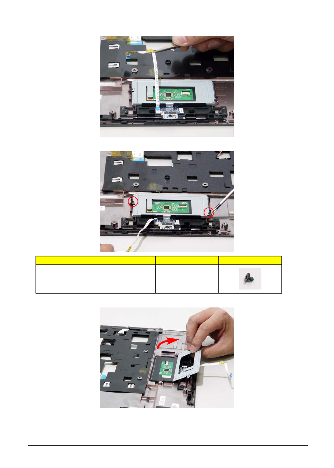
3. Move the Finger Print Reader FFC cable out of the way to prevent damage.
4. Remove the two securing screws from the Touch Pad bracket.
Step Size Quantity Screw Type
Touch Pad Bracket M2*3 (NL) 2
5. Remove the Touch Pad bracket.
IMPORTANT:The Touch Pad cannot be removed individually. To replace the Touch Pad, replace the entire
Upper Cover.
Chapter 3 73
Page 84
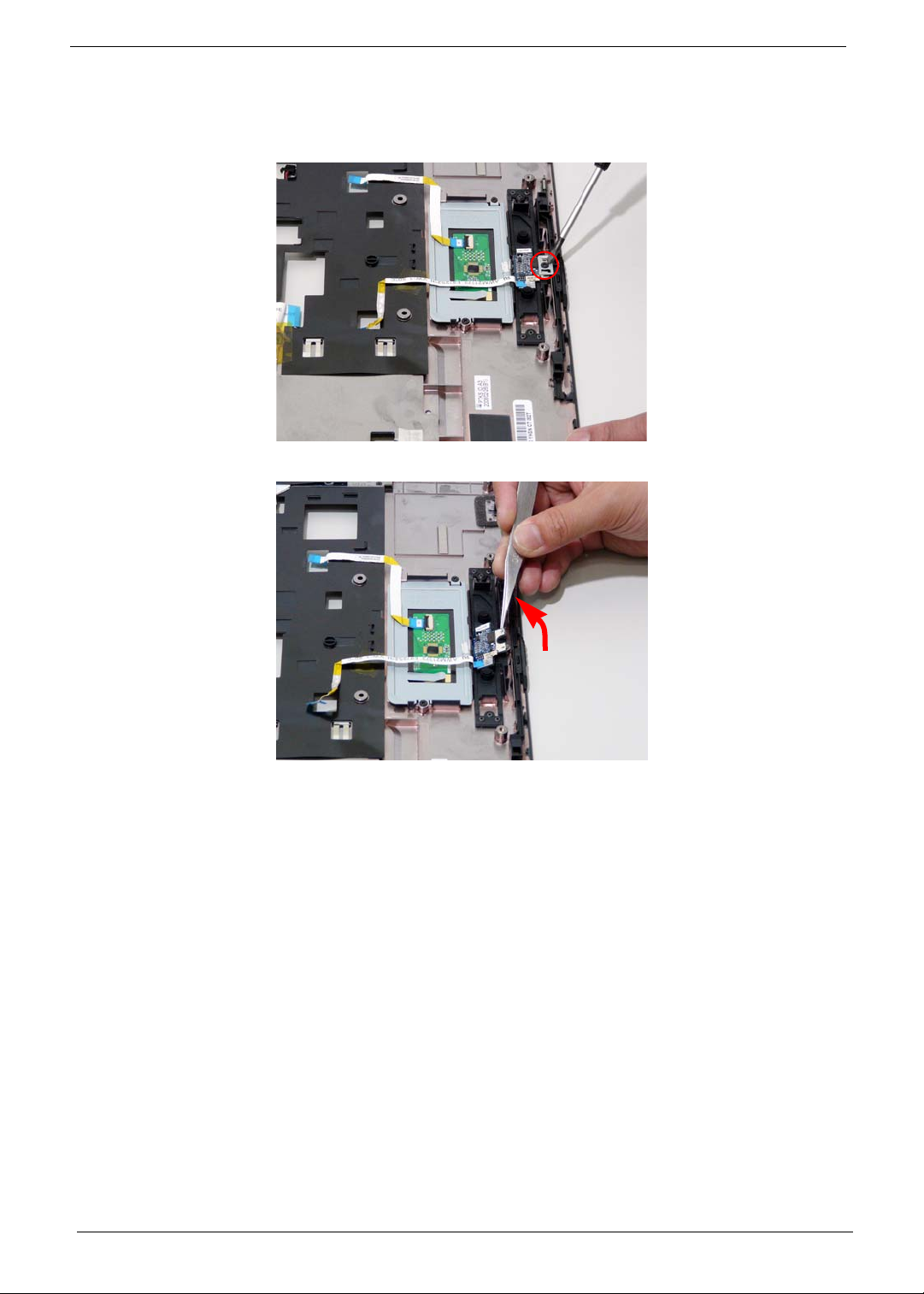
Removing the Finger Print Reader
1. See “Removing the Upper Cover” on page 68.
2. Remove the securing screw from the Finger Print Reader board.
3. Remove the Finger Print Reader board from the Upper Cover.
74 Chapter 3
Page 85
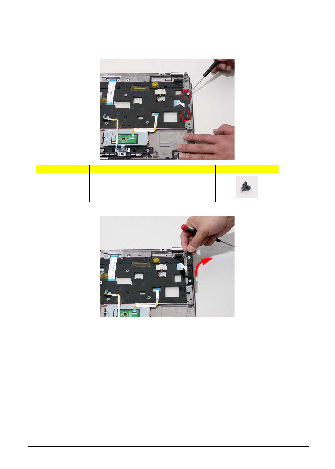
Removing the Launch Board
1. See “Removing the Upper Cover” on page 68.
2. Remove the two screws from the Launch Board.
Step Size Quantity Screw Type
Launch Board M2*3 (NL) 2
3. Remove the Launch Board from the Upper Cover.
Chapter 3 75
Page 86
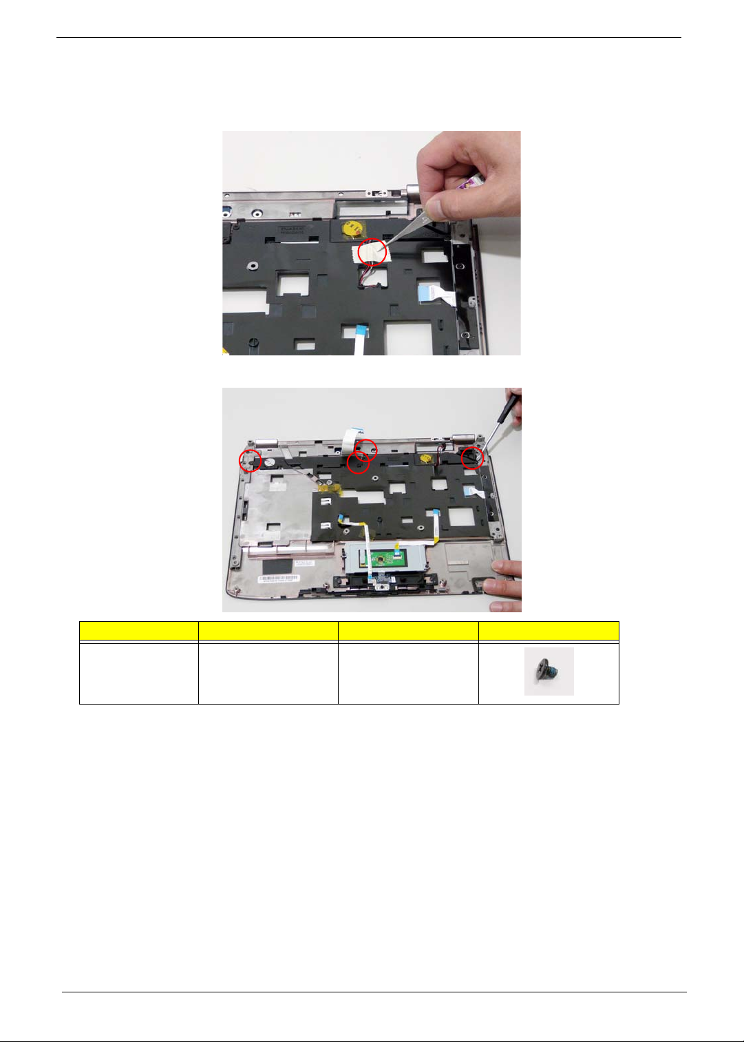
Removing the Speaker Module
1. See “Removing the Upper Cover” on page 68.
2. Remove the adhesive tape from the speaker cable.
3. Remove the four screws holding the Speaker Module in place.
Step Size Quantity Screw Type
Speaker M2*3 (NL) 4
76 Chapter 3
Page 87
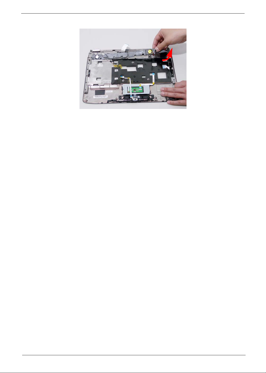
4. Remove the Speaker Module from the upper cover.
Chapter 3 77
Page 88
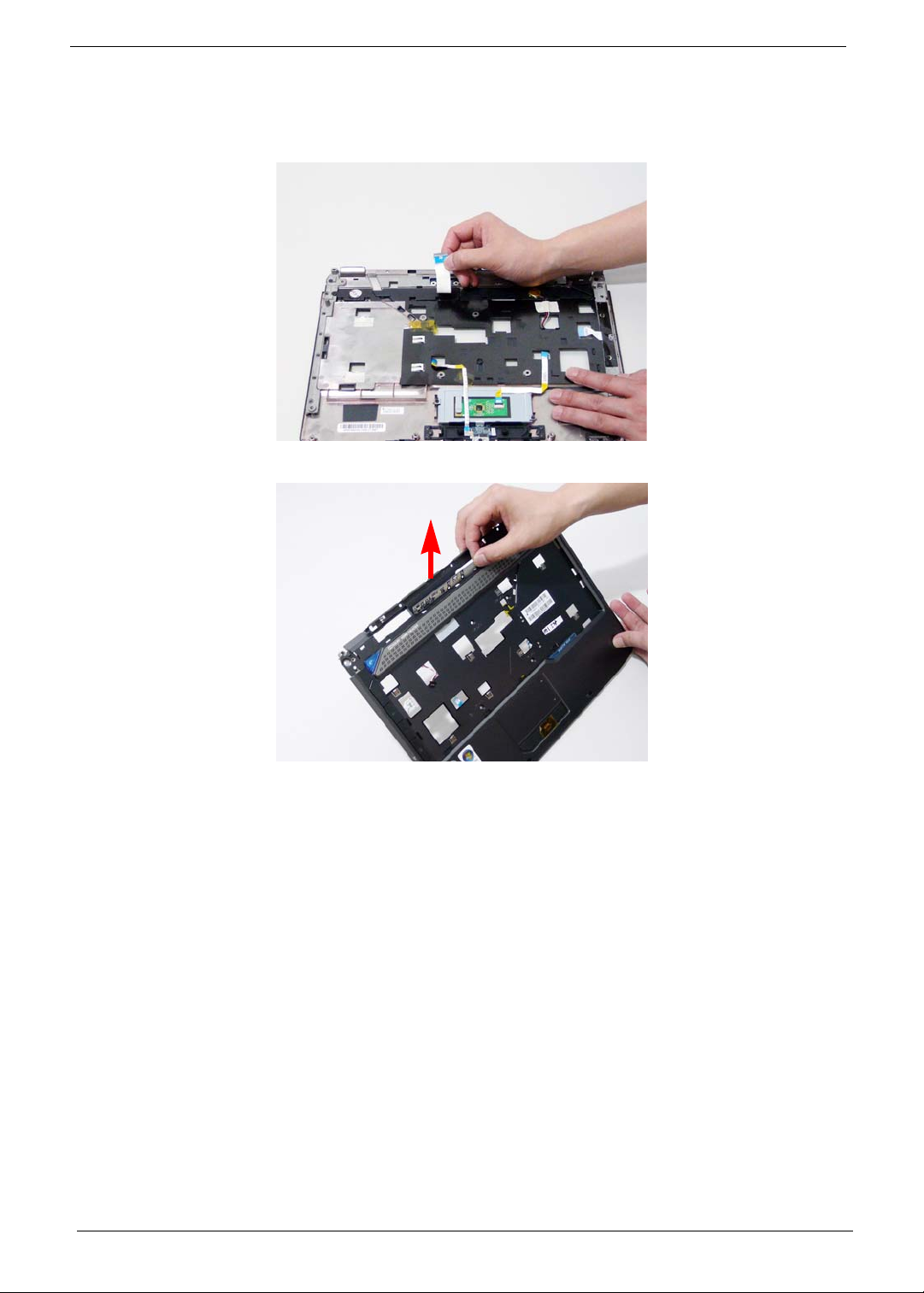
Removing the Switch Board
1. See “Removing the Upper Cover” on page 68.
2. Ensure the Switch Board cable is free from any obstructions.
3. Turn the Upper Cover. Remove the Switch Board as shown.
78 Chapter 3
Page 89
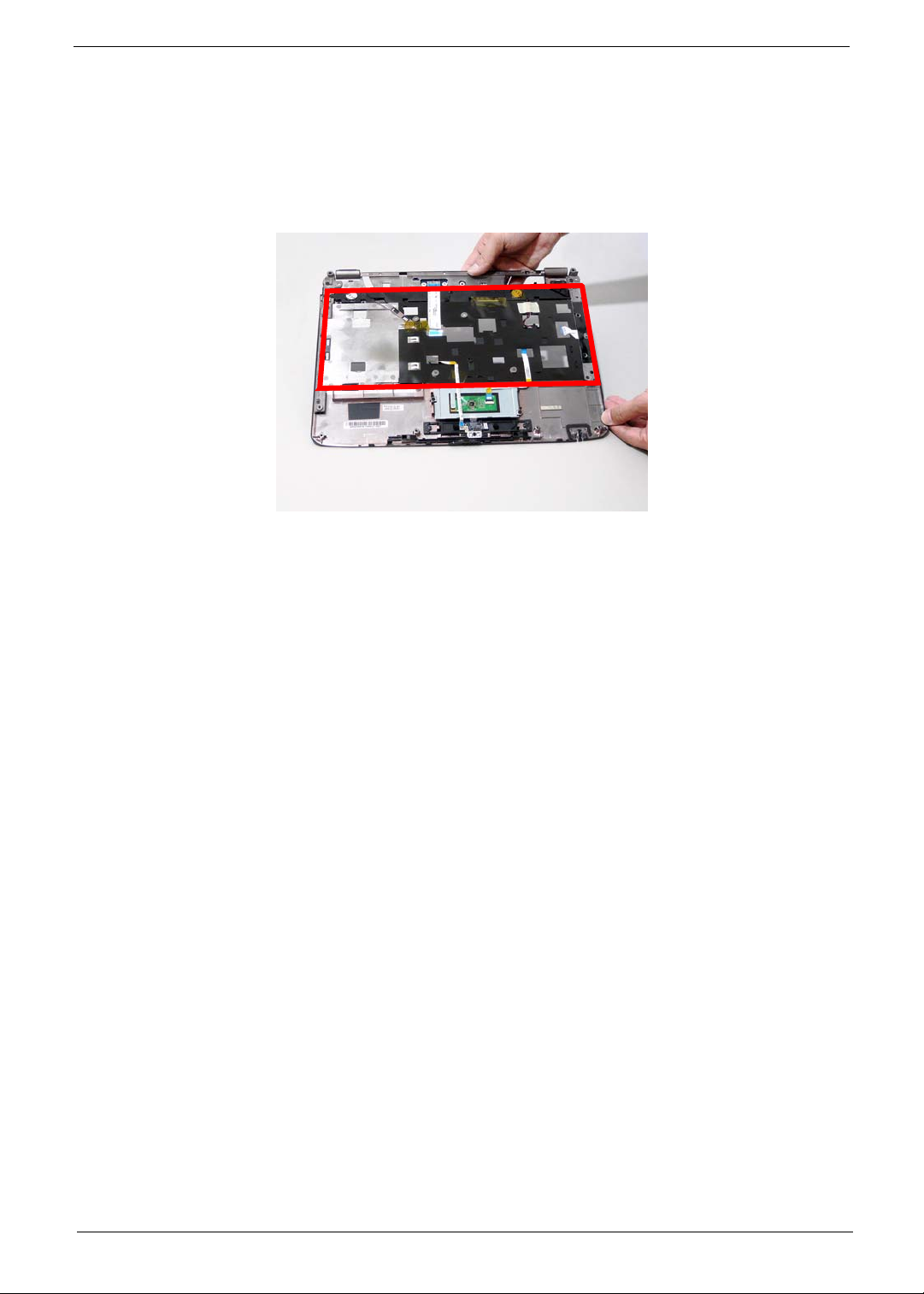
Removing the Touch Pad Board
IMPORTANT:The Touch Pad board is integrated into the design of the Upper Cover. To replace the Touch Pad
board, remove all components from the Upper Cover and install an entirely new Upper Cover.
IMPORTANT:The MOSFET pad is attached to the Upper Cover and is reusable. If the replacement Upper
Cover does not have a MOSFET pad (see highlighted area below), remove the MOSFET pad from
the replaced Upper Cover and stick it to the new Upper Cover.
1. See “Removing the Battery Pack” on page 44.
2. See “Removing the SD dummy card” on page 45.
3. See “Removing the ExpressCard dummy card” on page 46.
4. See “Removing the Lower Covers” on page 47.
5. See “Removing the DIMM Modules” on page 49.
6. See “Removing the WLAN Module” on page 50.
7. See “Removing the Hard Disk Drive Module” on page 52.
8. See “Removing the Optical Drive Module” on page 55.
9. See “Removing the Keyboard” on page 61.
10. See “Removing th e LCD Module” on page 66.
11. See “Removing the Upper Cover” on page 68.
12. See “Removing the Touch Pad Bracket” on page 72.
13. See “Removing the Finger Print Reader” on page 74.
14. See “Removing th e Launch Board” on page 75.
15. See “Removing the Speaker Module” on page 76.
16. See “Removing th e Switch Board” on page 78.
Chapter 3 79
Page 90
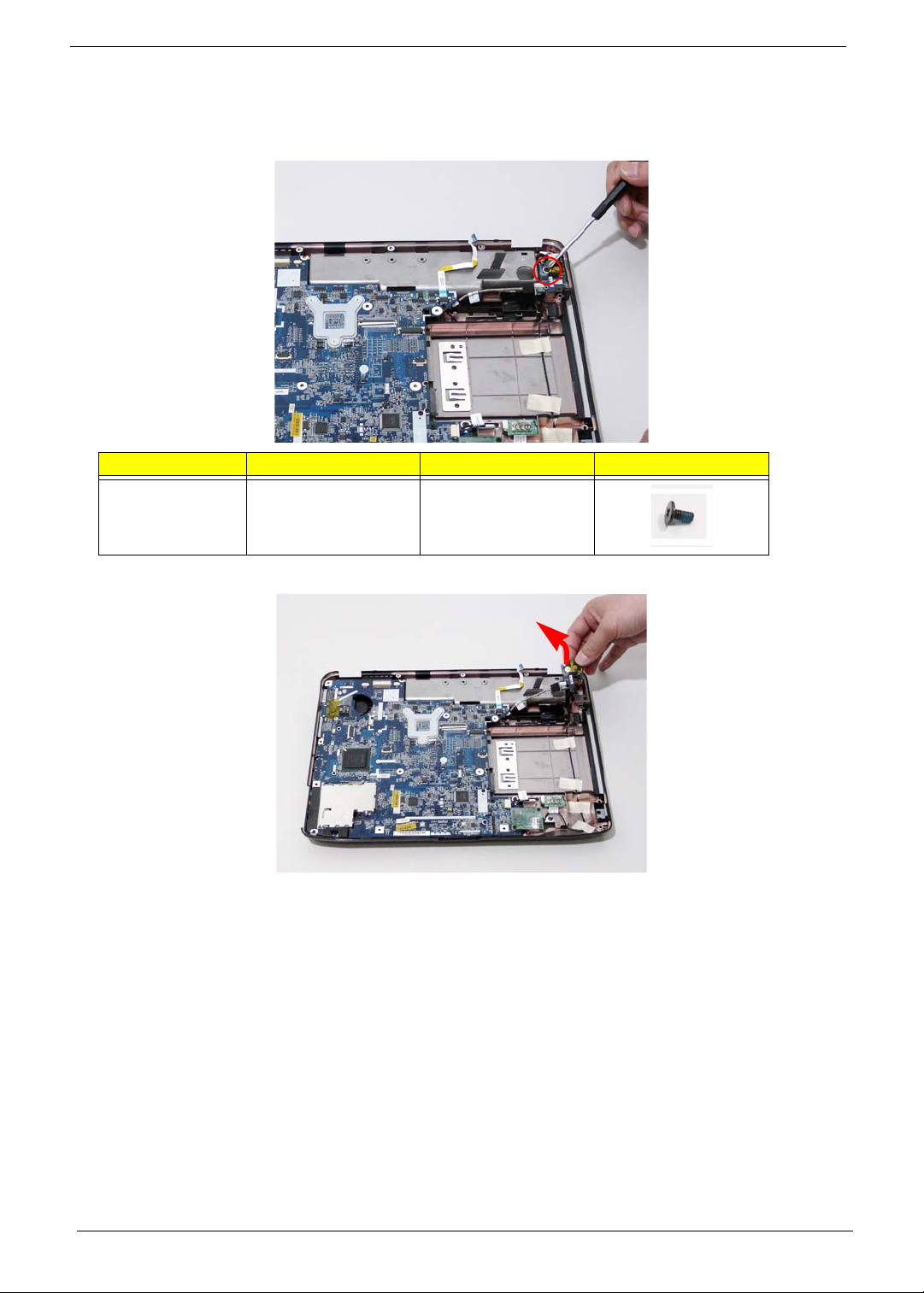
Removing the I/O Board
1. See “Removing the Upper Cover” on page 68.
2. Remove the securing screw from the I/O Board.
Step Size Quantity Screw Type
I/O Board M2.5*5 (NL) 1
3. Lift the I/O Board clear of the Lower cover.
80 Chapter 3
Page 91
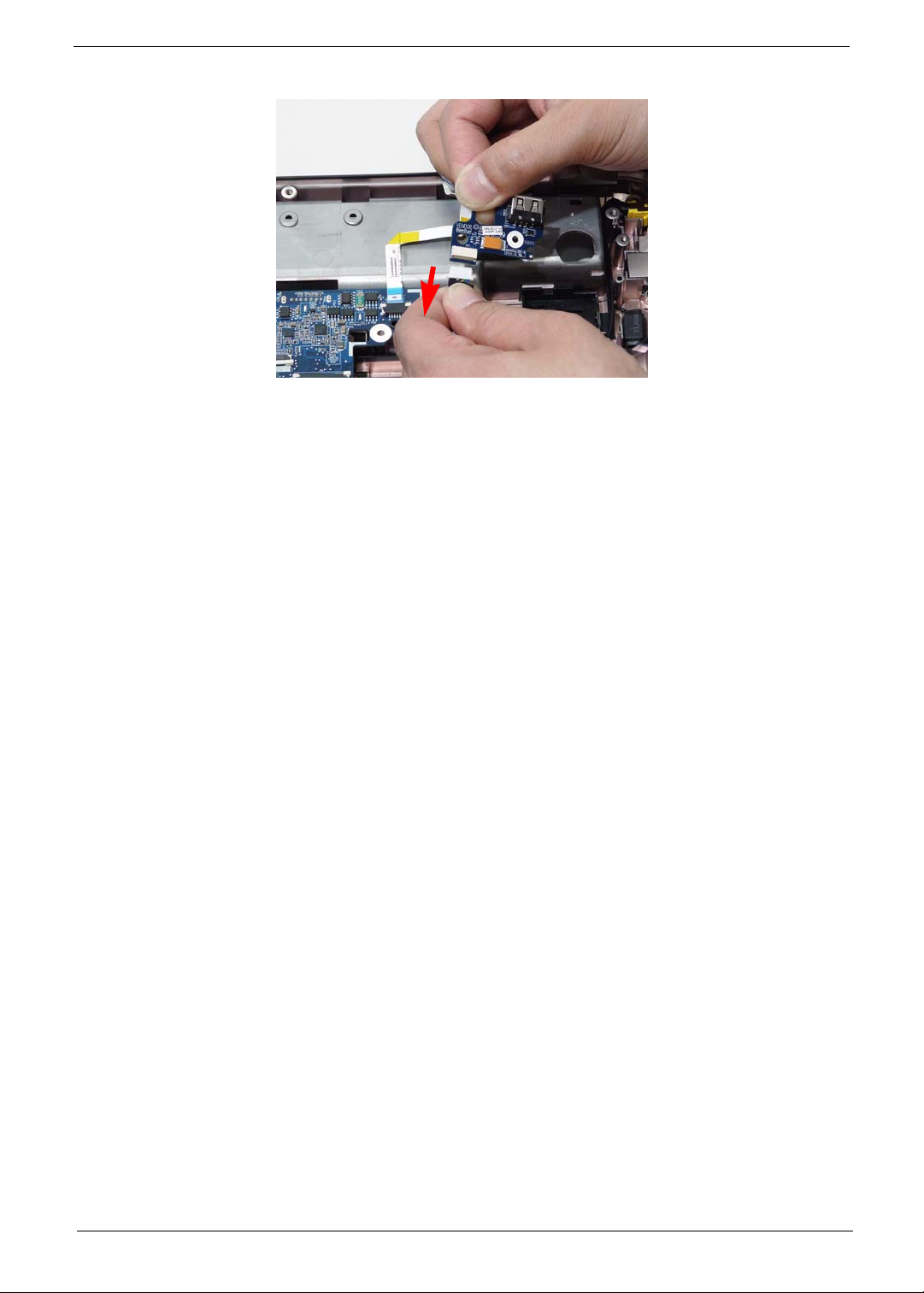
4. Disconnect the I/O Board cable and remove the board.
Chapter 3 81
Page 92
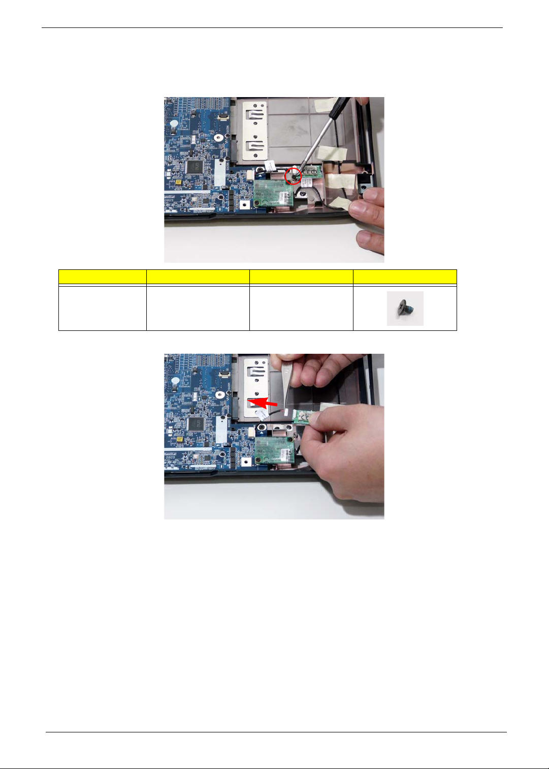
Removing the Bluetooth module
1. See “Removing the Upper Cover” on page 68.
2. Remove the securing screw from the Bluetooth module.
Step Size Quantity Screw Type
Bluetooth Board M2*3 (NL) 1
3. Lift the Bluetooth module away from the mainboard and disconnect the mainboard cable.
82 Chapter 3
Page 93
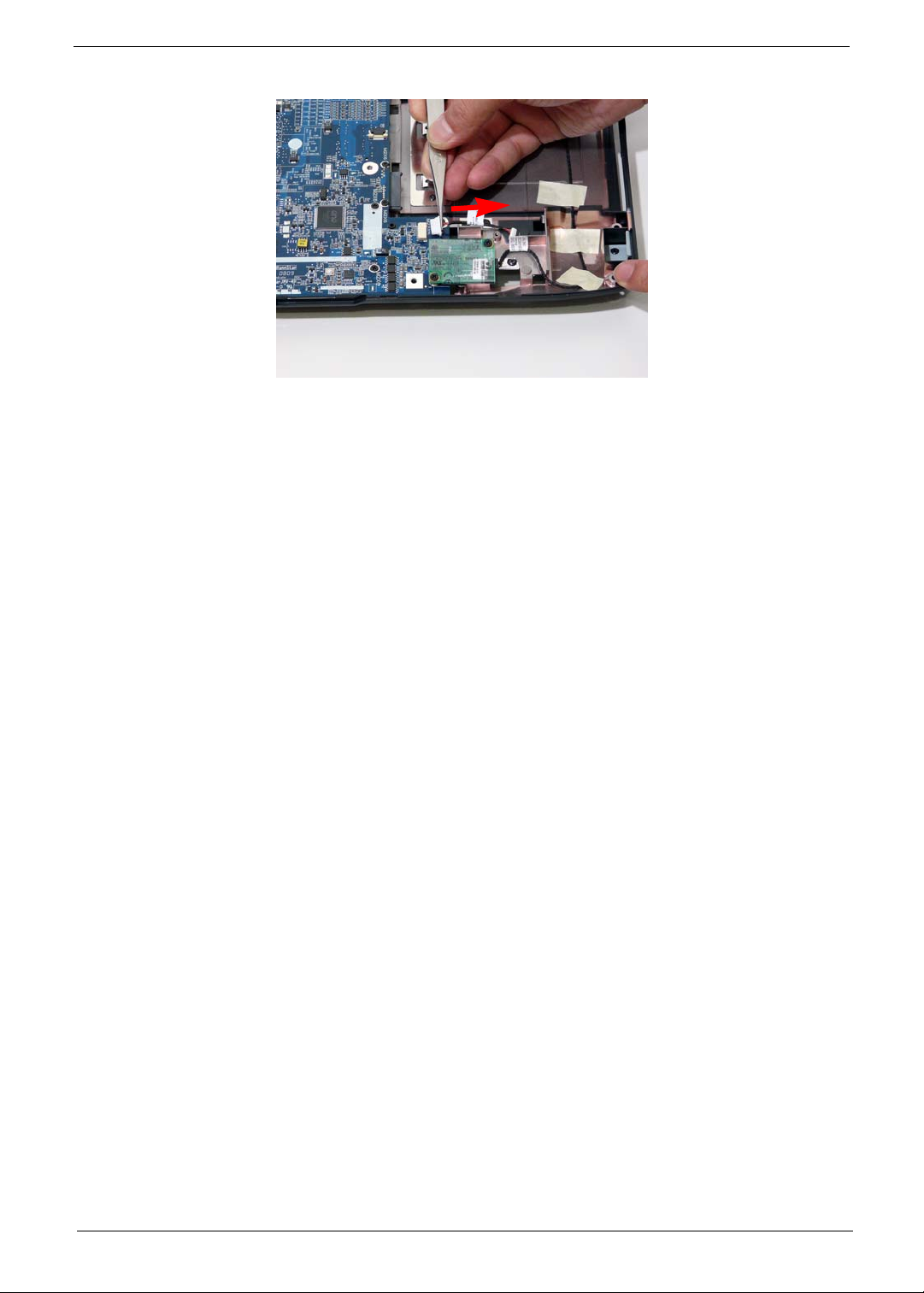
4. Disconnect the cable from the mainboard.
Chapter 3 83
Page 94
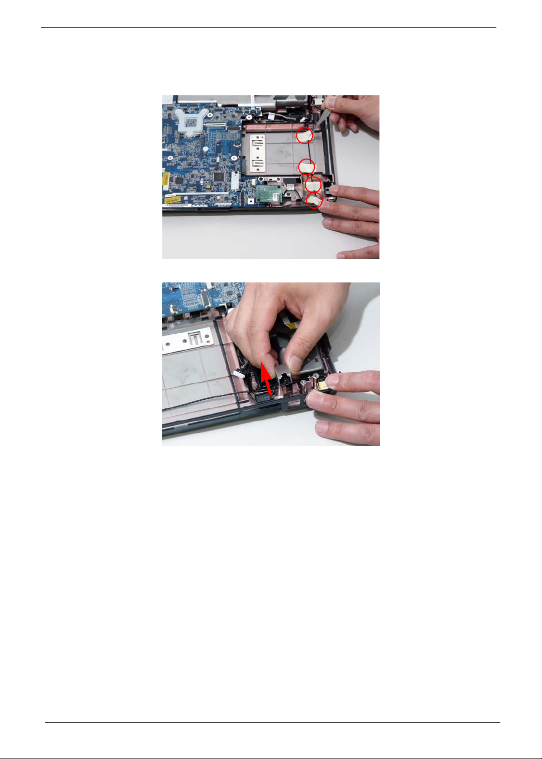
Removing the Modem Module
1. See “Removing the Upper Cover” on page 68.
2. Remove the adhesive strip securing the Modem cable to the Lower Cover.
3. Remove the RJ-11 port from the leftside of the Lower Cover.
84 Chapter 3
Page 95
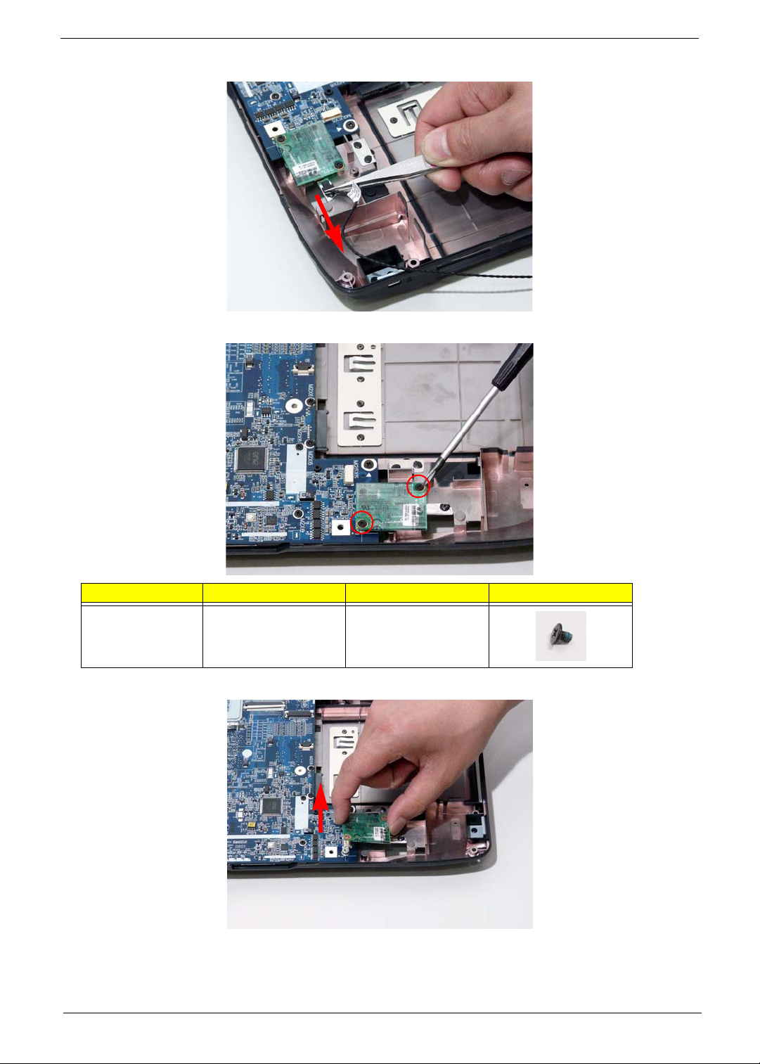
4. Disconnect the Modem cable from the Modem module.
5. Remove the two screws securing the Modem module.
Step Size Quantity Screw Type
Modem Module M2*3 (NL) 2
6. Remove the Modem module from the Lower Cover.
Chapter 3 85
Page 96
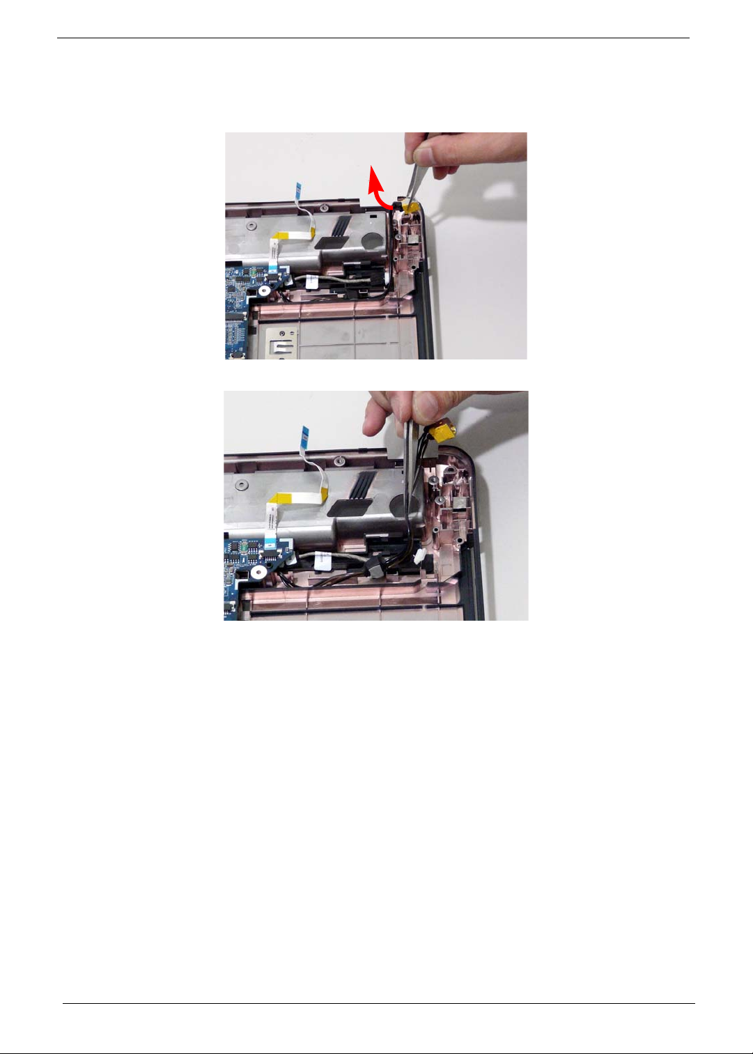
Removing the Main Board
1. See “Removing the Upper Cover” on page 68.
2. Disconnect the power jack from the power port on the Lower Cover.
3. Lift the cabling clear of the securing pins and ensure it is free of obstruction.
86 Chapter 3
Page 97
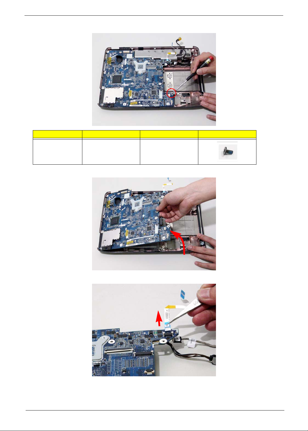
4. Remove the securing screw from the Mainboard.
Step Size Quantity Screw Type
Mainboard M2.5*5 (NL) 1
5. Remove the main board, rightside first, as shown.
6. Release the securing latches and remove the Switch Cover FFC.
Chapter 3 87
Page 98
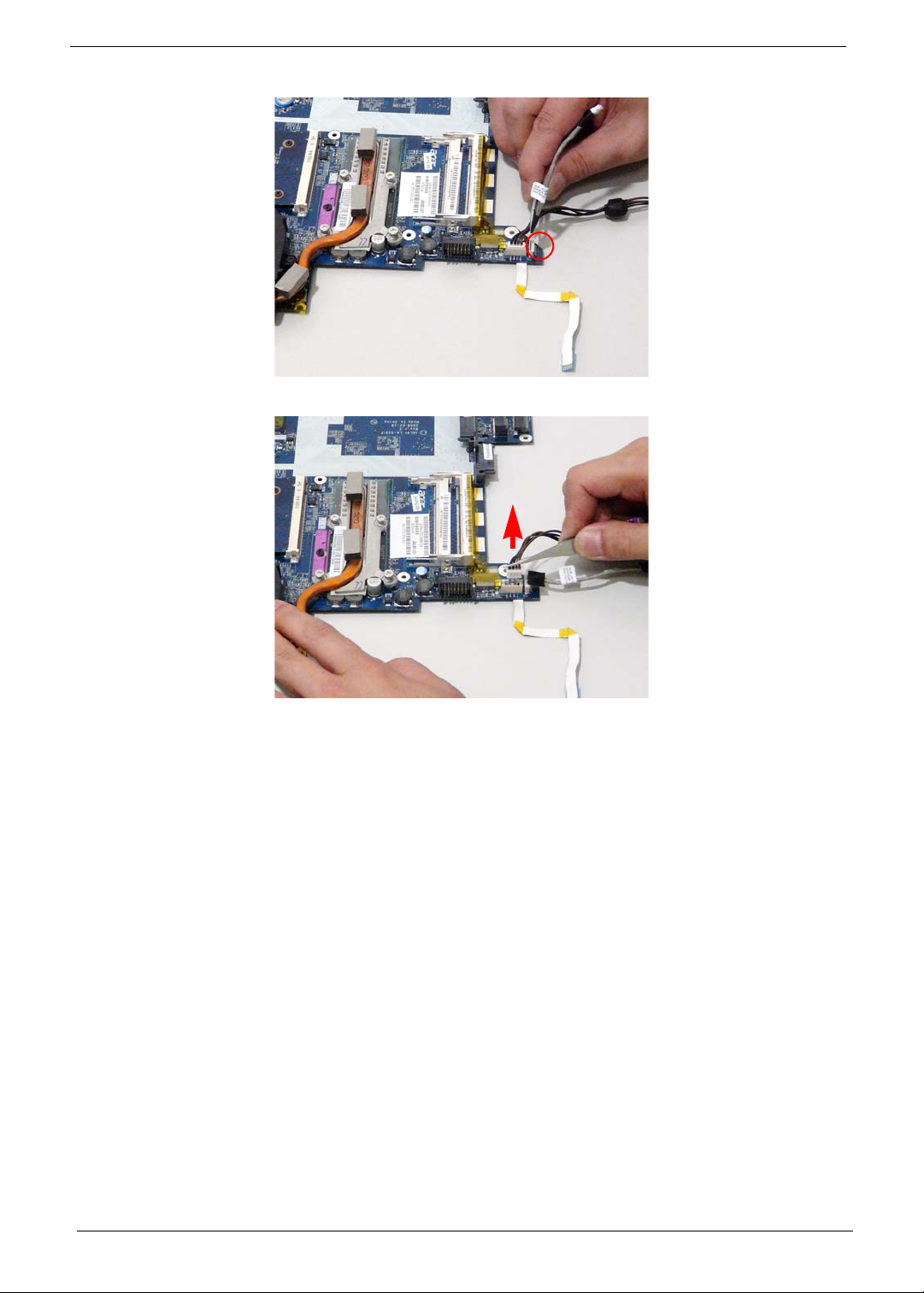
7. Turn the Mainboard over. Disconnect the I/O Cable from the Mainboard.
8. Disconnect the DC IN Cable from the Mainboard.
88 Chapter 3
Page 99
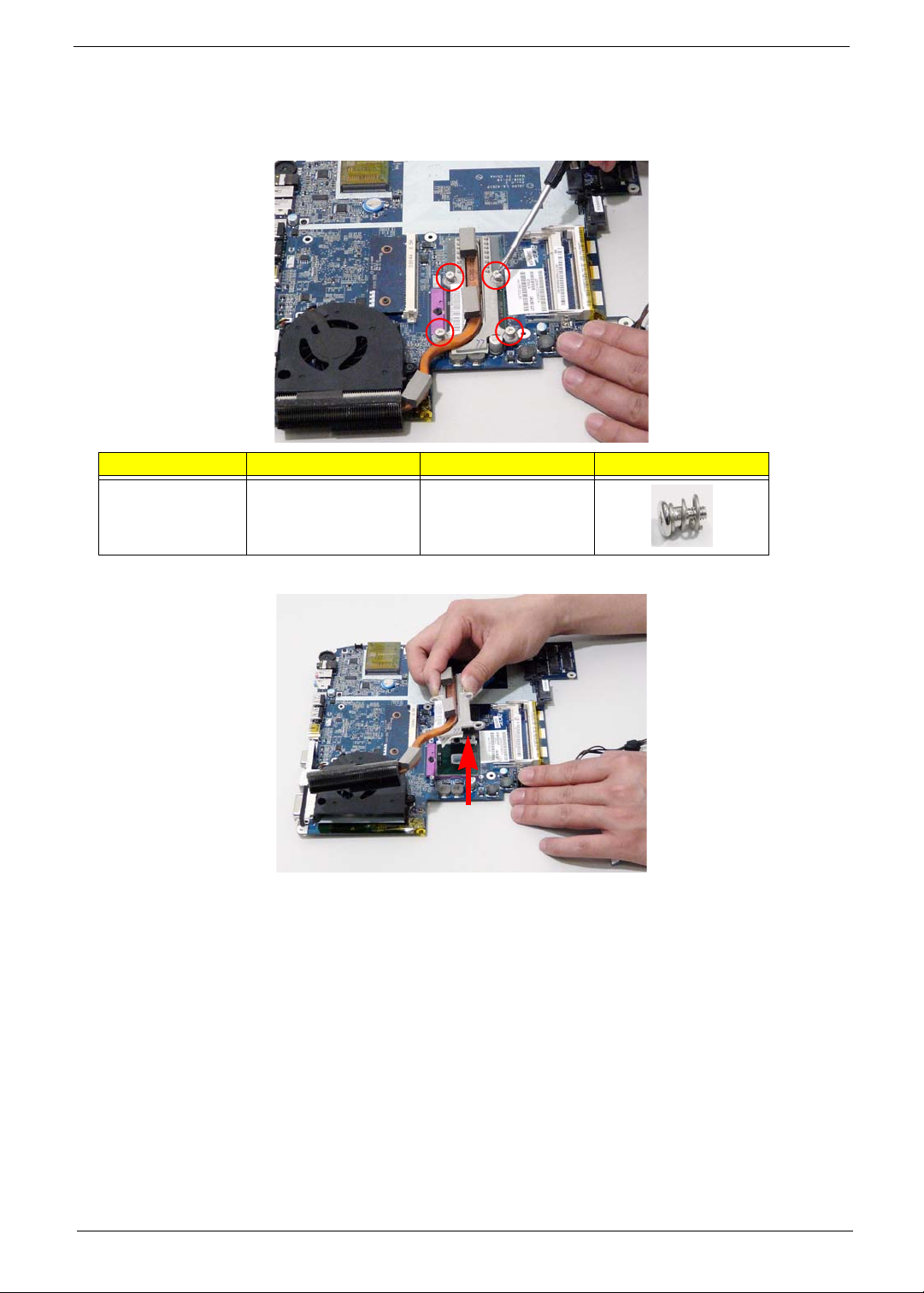
Removing the Thermal Module
1. See “Removing the Main Board” on page 86.
2. Remove the four securing screws from the Thermal Module.
Step Size Quantity Screw Type
Thermal Module M2.5*6.5 4
3. Lift the Thermal Module clear of the Mainboard.
Chapter 3 89
Page 100
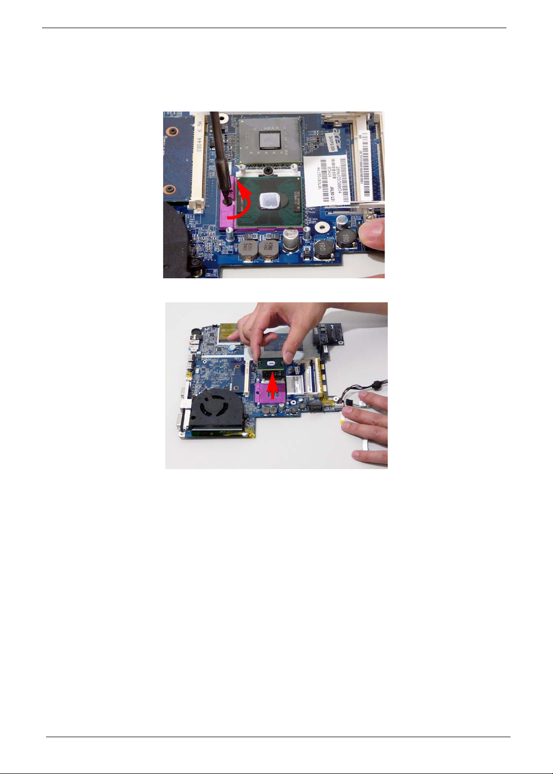
Removing the CPU
1. See “Removing the Main Board” on page 86.
2. See “Removing the Thermal Module” on page 89.
3. Using a flat screwdriver, turn the CPU socket latch counter-clockwise 180° to release the CPU.
k
4. Lift the CPU clear of the Mainboard.
90 Chapter 3
 Loading...