

Acer Aspire 4732Z, Aspire 4332 Service Manual
Acer Aspire 4732Z/4332
Notebook Computer Service Guide
Service guide files and updates are available
on the Acer/CSD web site; for more
information, go to
http://csd.acer.com.tw
PRINTED IN TAIWAN

Revision History
Refer to the table below for changes made on this version of the Acer Aspire 4732Z/4332 Notebook Computer Service Guide.
Date Chapter Updates
ii Acer Aspire 4732Z/4332 Service Guide

Copyright
Copyright © 2009 by Acer Incorporated. All rights reserved. No part of this publication may be reproduced,
transmitted, transcribed, stored in a retrieval system, or translated into any language or computer language, in
any form or by any means, electronic, mechanical, magnetic, optical, chemical, manual or otherwise, without
the prior written permission of Acer Incorporated.
Disclaimer
The information in this guide is subject to change without notice.
Acer Incorporated makes no representations or warranties, either expressed or implied, with respect to the
contents hereof and specifically disclaims any warranties of merchantability or fitness for any particular
purpose. Any Acer Incorporated software described in this guide is sold or licensed "as is". Should the
programs prove defective following their purchase, the buyer (and not Acer Incorporated, its distributor, or its
dealer) assumes the entire cost of all necessary servicing, repair, and any incidental or consequential
damages resulting from any defect in the software.
Acer is a registered trademark of Acer Incorporated.
Other brand and product names are trademarks and/or registered trademarks of their respective holders.
Acer Aspire 4732Z/4332 Service Guide iii

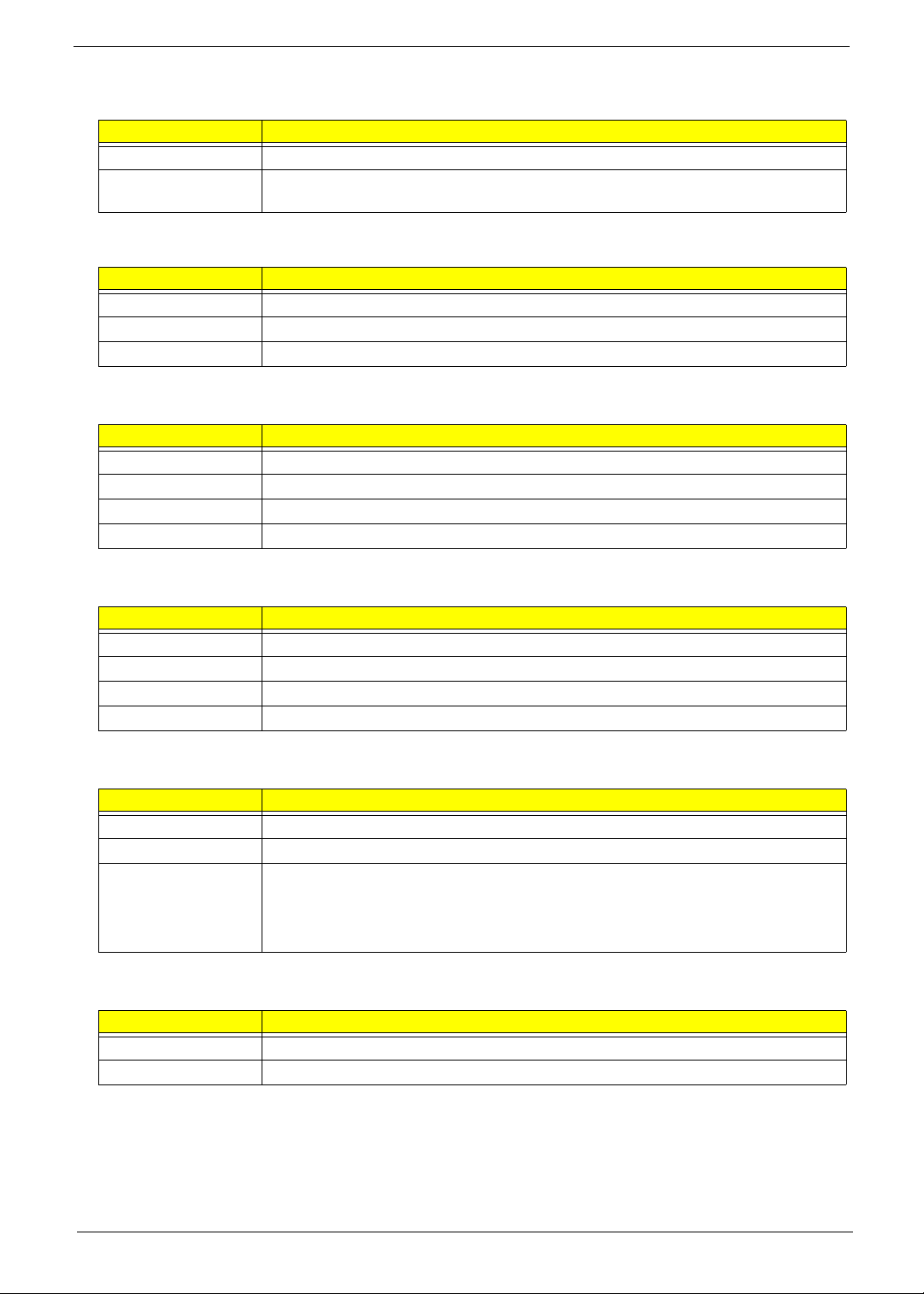
Conventions
The following textual conventions are used in this service guide.
SCREEN MESSAGES Denotes actual messages that appear on screen.
NOTE Gives additional information related to the current topic.
WARNING Alerts you to any physical risk or system damage that might result from
doing or not doing specific actions.
CAUTION Gives precautionary measures to avoid possible hardware or software
problems.
IMPORTANT Reminds you to do specific actions relevant to the accomplishment of
procedures.
iv Acer Aspire 4732Z/4332 Service Guide

Service Guide Coverage
This Service Guide provides you with all technical information relating to the BASIC CONFIGURATION
decided for our "global" product offering. To better fit local market requirements and enhance product
competitiveness, your regional office MAY have decided to extend the functionality of a machine (e.g. add-on
card, modem, or extra memory capability). These LOCALIZED FEATURES will NOT be covered in this generic
service guide. In such cases, please contact your regional offices or the responsible personnel/channel to
provide you with further technical details.
FRU Information
Please note WHEN ORDERING FRU PARTS, that you should check the most up-to-date information available
on your regional web or channel. If, for whatever reason, a part number change is made, it will not be noted in
the printed service guide. For AUTHORIZED SERVICE PROVIDERS, your office may have a DIFFERENT
part number code to those given in the FRU list of this printed service guide. You MUST use the list provided
by your regional Acer office to order FRU parts for repair and service of customer machines.
Acer Aspire 4732Z/4332 Service Guide v

vi Acer Aspire 4732Z/4332 Service Guide

Table of Contents
Chapter 1 Features and Specifications 1
Features . . . . . . . . . . . . . . . . . . . . . . . . . . . . . . . . . . . . . . . . . . . . . . . . . . . . . . . . . . . . .1
Hardware . . . . . . . . . . . . . . . . . . . . . . . . . . . . . . . . . . . . . . . . . . . . . . . . . . . . . . .1
Display and Camera . . . . . . . . . . . . . . . . . . . . . . . . . . . . . . . . . . . . . . . . . . . . . . .2
Keyboard and Pointing Device . . . . . . . . . . . . . . . . . . . . . . . . . . . . . . . . . . . . . . . .2
LED Indicators and Buttons . . . . . . . . . . . . . . . . . . . . . . . . . . . . . . . . . . . . . . . . . . .2
Software . . . . . . . . . . . . . . . . . . . . . . . . . . . . . . . . . . . . . . . . . . . . . . . . . . . . . . . .2
Ergonomics and Security . . . . . . . . . . . . . . . . . . . . . . . . . . . . . . . . . . . . . . . . . . . .3
Environmental Requirements . . . . . . . . . . . . . . . . . . . . . . . . . . . . . . . . . . . . . . . . .3
System Tour . . . . . . . . . . . . . . . . . . . . . . . . . . . . . . . . . . . . . . . . . . . . . . . . . . . . . . . . . .4
Top View . . . . . . . . . . . . . . . . . . . . . . . . . . . . . . . . . . . . . . . . . . . . . . . . . . . . . . . .4
Closed Front View . . . . . . . . . . . . . . . . . . . . . . . . . . . . . . . . . . . . . . . . . . . . . . . . .5
Rear View . . . . . . . . . . . . . . . . . . . . . . . . . . . . . . . . . . . . . . . . . . . . . . . . . . . . . . .6
Left View . . . . . . . . . . . . . . . . . . . . . . . . . . . . . . . . . . . . . . . . . . . . . . . . . . . . . . . .6
Right View . . . . . . . . . . . . . . . . . . . . . . . . . . . . . . . . . . . . . . . . . . . . . . . . . . . . . .7
Base View . . . . . . . . . . . . . . . . . . . . . . . . . . . . . . . . . . . . . . . . . . . . . . . . . . . . . . .7
Specifications . . . . . . . . . . . . . . . . . . . . . . . . . . . . . . . . . . . . . . . . . . . . . . . . . . . . . . . . .8
Chapter 2 System Utilities 15
Phoenix SecureCore Setup Utility . . . . . . . . . . . . . . . . . . . . . . . . . . . . . . . . . . . . . . . . .15
Accessing the Setup Utility . . . . . . . . . . . . . . . . . . . . . . . . . . . . . . . . . . . . . . . . . .16
Navigating through the Setup Utility . . . . . . . . . . . . . . . . . . . . . . . . . . . . . . . . . . .17
Setup Utility Menus . . . . . . . . . . . . . . . . . . . . . . . . . . . . . . . . . . . . . . . . . . . . . . .17
Chapter 3 System Disassembly 25
Disassembly Tools . . . . . . . . . . . . . . . . . . . . . . . . . . . . . . . . . . . . . . . . . . . . . . . . . . . .25
Stages of the Disassembly Process . . . . . . . . . . . . . . . . . . . . . . . . . . . . . . . . . . . . . . . .25
Equivalent Torque Values . . . . . . . . . . . . . . . . . . . . . . . . . . . . . . . . . . . . . . . . . . . . . . .25
System Screw List . . . . . . . . . . . . . . . . . . . . . . . . . . . . . . . . . . . . . . . . . . . . . . . . . . . . .26
Pre-disassembly Procedure . . . . . . . . . . . . . . . . . . . . . . . . . . . . . . . . . . . . . . . . . . . . . .26
External Modules Disassembly . . . . . . . . . . . . . . . . . . . . . . . . . . . . . . . . . . . . . . . . . . .27
External Modules Disassembly Flowchart . . . . . . . . . . . . . . . . . . . . . . . . . . . . . . .27
Removing the Battery Pack . . . . . . . . . . . . . . . . . . . . . . . . . . . . . . . . . . . . . . . . . .28
Removing the xD Dummy Card . . . . . . . . . . . . . . . . . . . . . . . . . . . . . . . . . . . . . .28
Removing the Lower Case Cover . . . . . . . . . . . . . . . . . . . . . . . . . . . . . . . . . . . . .29
Removing the Memory Modules . . . . . . . . . . . . . . . . . . . . . . . . . . . . . . . . . . . . .30
Removing the Hard Disk Drive . . . . . . . . . . . . . . . . . . . . . . . . . . . . . . . . . . . . . . .31
Removing the WLAN Module . . . . . . . . . . . . . . . . . . . . . . . . . . . . . . . . . . . . . . .32
Removing the Optical Disc Drive . . . . . . . . . . . . . . . . . . . . . . . . . . . . . . . . . . . . . .34
Main Unit Disassembly . . . . . . . . . . . . . . . . . . . . . . . . . . . . . . . . . . . . . . . . . . . . . . . . .36
Main Unit Disassembly Flowchart . . . . . . . . . . . . . . . . . . . . . . . . . . . . . . . . . . . .36
Removing the Middle Cover . . . . . . . . . . . . . . . . . . . . . . . . . . . . . . . . . . . . . . . .37
Removing the Keyboard . . . . . . . . . . . . . . . . . . . . . . . . . . . . . . . . . . . . . . . . . . .37
Removing the LCD Module . . . . . . . . . . . . . . . . . . . . . . . . . . . . . . . . . . . . . . . . .38
Removing the Upper Case . . . . . . . . . . . . . . . . . . . . . . . . . . . . . . . . . . . . . . . . . .41
Removing the Speakers . . . . . . . . . . . . . . . . . . . . . . . . . . . . . . . . . . . . . . . . . . . .43
Removing the Power Board . . . . . . . . . . . . . . . . . . . . . . . . . . . . . . . . . . . . . . . . .44
Removing the Touchpad Board . . . . . . . . . . . . . . . . . . . . . . . . . . . . . . . . . . . . . .45
Removing the Mainboard . . . . . . . . . . . . . . . . . . . . . . . . . . . . . . . . . . . . . . . . . .47
Removing the Heat Sink Fan (HSF) Assembly . . . . . . . . . . . . . . . . . . . . . . . . . . . .47
vii Acer Aspire 4732Z/4332 Service Guide

Table of Contents
Removing the Processor . . . . . . . . . . . . . . . . . . . . . . . . . . . . . . . . . . . . . . . . . . .48
LCD Module Disassembly . . . . . . . . . . . . . . . . . . . . . . . . . . . . . . . . . . . . . . . . . . . . . .50
LCD Module Disassembly Flowchart . . . . . . . . . . . . . . . . . . . . . . . . . . . . . . . . . .50
Removing the LCD Bezel . . . . . . . . . . . . . . . . . . . . . . . . . . . . . . . . . . . . . . . . . .51
Removing the Lid Magnet . . . . . . . . . . . . . . . . . . . . . . . . . . . . . . . . . . . . . . . . . .52
Removing the LCD Panel . . . . . . . . . . . . . . . . . . . . . . . . . . . . . . . . . . . . . . . . . . .53
Removing the LCD-CCD Coaxial Cable . . . . . . . . . . . . . . . . . . . . . . . . . . . . . . . .54
Removing the LCD Panel Brackets . . . . . . . . . . . . . . . . . . . . . . . . . . . . . . . . . . . .55
Removing the CCD Board . . . . . . . . . . . . . . . . . . . . . . . . . . . . . . . . . . . . . . . . . .56
Chapter 4 Troubleshooting 57
POST Error Indicators . . . . . . . . . . . . . . . . . . . . . . . . . . . . . . . . . . . . . . . . . . . . . . . . . .57
POST Error Messages . . . . . . . . . . . . . . . . . . . . . . . . . . . . . . . . . . . . . . . . . . . . . .57
POST Beep Codes . . . . . . . . . . . . . . . . . . . . . . . . . . . . . . . . . . . . . . . . . . . . . . . . .59
BIOS Beep Codes for Boot Block in Flash ROM . . . . . . . . . . . . . . . . . . . . . . . . . . .62
Troubleshooting Procedure . . . . . . . . . . . . . . . . . . . . . . . . . . . . . . . . . . . . . . . . . . . . .63
System Check Procedures . . . . . . . . . . . . . . . . . . . . . . . . . . . . . . . . . . . . . . . . . . .63
Intermittent Problems . . . . . . . . . . . . . . . . . . . . . . . . . . . . . . . . . . . . . . . . . . . . . .65
Undetermined Problems . . . . . . . . . . . . . . . . . . . . . . . . . . . . . . . . . . . . . . . . . . . .65
Chapter 5 System Architecture 67
Block Diagram . . . . . . . . . . . . . . . . . . . . . . . . . . . . . . . . . . . . . . . . . . . . . . . . . . . . . . .67
Mainboard Layout . . . . . . . . . . . . . . . . . . . . . . . . . . . . . . . . . . . . . . . . . . . . . . . . . . . .68
Top View . . . . . . . . . . . . . . . . . . . . . . . . . . . . . . . . . . . . . . . . . . . . . . . . . . . . . . .68
Bottom View . . . . . . . . . . . . . . . . . . . . . . . . . . . . . . . . . . . . . . . . . . . . . . . . . . . .69
Clearing a BIOS Password . . . . . . . . . . . . . . . . . . . . . . . . . . . . . . . . . . . . . . . . . . . . . . .70
Unlocking the HDD . . . . . . . . . . . . . . . . . . . . . . . . . . . . . . . . . . . . . . . . . . . . . . . . . . .71
BIOS Recovery . . . . . . . . . . . . . . . . . . . . . . . . . . . . . . . . . . . . . . . . . . . . . . . . . . . . . . .71
Creating the BIOS Crisis Recovery Disk . . . . . . . . . . . . . . . . . . . . . . . . . . . . . . . . .71
Performing a BIOS Recovery . . . . . . . . . . . . . . . . . . . . . . . . . . . . . . . . . . . . . . . . .72
Chapter 6 Field Replaceable Unit (FRU) List 73
Acer Aspire 4732Z/4332 Exploded Diagram . . . . . . . . . . . . . . . . . . . . . . . . . . . . . . . .74
Acer Aspire 4732Z/4332 FRU List . . . . . . . . . . . . . . . . . . . . . . . . . . . . . . . . . . . . . . . . .78
Appendix A Model Definition and Configurations 86
Appendix B Test Compatible Components 87
Appendix C Online Support Information 90
Index 91
Acer Aspire 4732Z/4332 Service Guide viii

Features and Specifications
This chapter lists the features and specifications of the Acer Aspire 4732Z/4332 computer.
Features
This tables in this section list the system features and environmental requirements of the computer.
NOTE: The specifications listed in this section are for reference only. The exact configuration of your PC
depends on the model purchased.
Hardware
Component Description
Processor Intel Pentium Processors for Mobile or Mobile Intel Celeron Processors
System chipset • Mobile Intel GL40 Express Chipset
• Intel I/O Controller Hub 9M (ICH9M)
Memory • Two DIMM slots supporting DDR2 677 MHz modules
Expansion options • 5-in-1 card reader slot
Media storage • 2.5-inch 9.5 mm SATA hard disk drive (HDD)
Connectivity • Atheros AR8114 PCI-E Ethernet Controller
I/O ports • VGA port
Audio • High-definition audio system
Power supply • 6-cell 48.8 W 4400 mAh Lithium Ion battery pack
Physical specifications • Dimension (W×D×H): 337 x 227 x 26/39.9 mm (13.27 x 8.94 x 1.02/1.6 in)
• Maximum memory of 2 GB for 32-bit OS or 4 GB for 64-bit OS
• 2 MB Flash BIOS; shadow RAM support
• Supports MultiMediaCard (MMC), Secure Digital (SD), xD-Picture Card
(xD), Memory Stick (MS), and Memory Stick PRO (MS PRO) cards
• Slim type Super Multi optical disc drive (ODD)
• WLAN module compliant with 802.11 b/g and a/b/g/n standards
• External V.92 56 Kbps USB 1.5 modem
• Broadcom Blutonium BCM2045 Bluetooth module (optional)
• Ethernet port (RJ-45)
• Two USB 2.0 ports
• Microphone-in jack
• Headphones/speaker/Line-out jack
• DC-in jack for AC adapter
• MS-Sound compatible
• Two built-in stereo speakers
• Microphone-in and line-out jacks
• 3-pin 65 W 19V AC adapter
• Charging period:1.5–2 hours for 0–80%, 3–3.5 hours for 0–99%,
3.5–4 hours for 0–100% (charge-in-use)
• ENERGY STAR
• Weight: 2.4 kg (5.29 lb)
Chapter 1
Aspire 4732Z/4332 Service Guide1
Display and Camera
Component Description
Display type • 14” WXGA LCD panel
• Supported resolutions: 1366×768, 1360×768, 1280×768, 1280×720,
1024×768, and 800×600
• 16:9 aspect ratio
• Simultaneous multi-window viewing via Acer GridVista
• Function control keys for manual adjustment of the display panel
brightness level
Webcam 0.3M pixel webcam
Keyboard and Pointing Device
Component Description
Keyboard • 86-/87-/91-key EM4T series keyboard with embedded numeric keypad,
inverted-T cursor keys, Internet scroll key, and 12 function keys (hotkeys)
• Multilanguage support
• Spill-proof
Pointing device • Up/down scroll segment
• Touchpad on/off function
• Adjustable touchpad sensitivity function
• Spill-resistant
LED Indicators and Buttons
Component Description
LED indicators • Power (blue)
• Battery (blue/amber)
• HDD access (blue)
• Num Lock (blue)
• Caps Lock (blue)
Buttons with LED indicator • Touchpad on/off (blue/orange)
• Power (blue)
• WLAN (blue/orange)
Software
Aspect Description
Operating system support Microsoft Genuine Windows Vista
Antivirus software Norton Internet Security
Power management ACPI 3.0 (Advanced Configuration Power Interface) standard
2 Aspire 4732Z/4332 Service Guide
Ergonomics and Security
Aspect Description
Ergonomics • Spill-resistant keyboard and touchpad
Security • BIOS-based user, supervisor, and HDD passwords
• Status LED indicators allows constant monitoring of basic system functions
• Function control keys allows convenient control of various system
operations
• User-programmable launch button for priority applications
• DIY HDD and memory upgrade options
• High-capacity, rechargeable battery pack
• ACPI-compliant power management system
• Kensington lock
Environmental Requirements
Aspect Description
Temperature Operating: 5 to 35 °C (41 to 95 °F)
Non-operating: -20 to 65 °C
Humidity (non-condensing) Operating: 20% to 80% RH non-condensing
Non-operating: 20% to 80% RH non-condensing
Aspire 4732Z/4332 Service Guide 3
System Tour
The pictures and tables in this section illustrate the physical outlook of the computer.
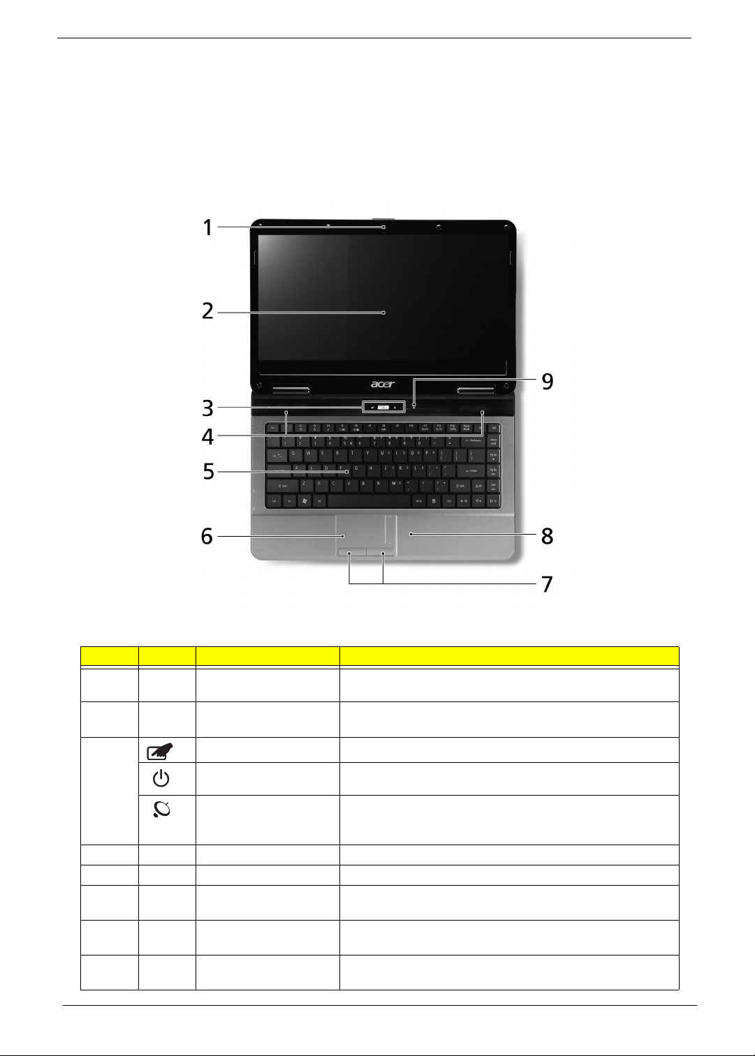
Top View
Item Icon Component Function
1 Integrated webcam Web camera for video communication. (only for certain
models)
2 Display screen Also called Liquid Crystal Display (LCD), displays computer
output.
3 Touchpad button Toggles the touchpad on and off.
Power button Turns the computer on and off.
Wireless LAN (WLAN)
communication button/
indicator
4 Speakers Left and right speakers deliver stereo audio output.
5 Keyboard For entering data into your computer.
6 Touchpad Touch-sensitive pointing device which functions like a
7 Click buttons The left and right buttons function like the left and right
8 Palmrest Comfortable support area for your hands when you use the
4 Aspire 4732Z/4332 Service Guide
Enables/disables the WLAN function and indicates its status.
computer mouse.
mouse buttons.
computer.
Item Icon Component Function
9 HDD indicator Lights up when there is hard drive access.
Hotkeys
The computer employs hotkeys or key combinations to access most of the computer's controls like screen
brightness and volume output.
To activate hotkeys, press and hold the <Fn> key before pressing the other key in the hotkey combination
Hotkey Icon Function Description
<Fn> + <F4> Sleep Puts the computer in Sleep mode.
<Fn> + <F5> Display toggle Switches display output between the display screen,
an external monitor (if connected) and both.
<Fn> + <F6> Screen blank Turns the display screen backlight off to save power.
Press any key to turn it back on.
<Fn> + <F8> Speaker toggle Turns the speakers on and off.
.
<Fn> + < >
<Fn> + < >
<Fn> + < >
<Fn> + < >
Volum e up Increases the sound volume.
Volum e down Decreases the sound volume.
Brightness up Increases the screen brightness.
Brightness down Decreases the screen brightness.
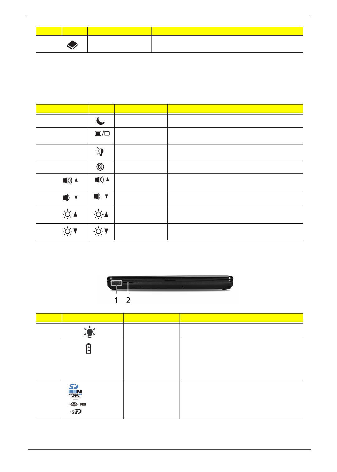
Closed Front View
Item Icon Component Function
1 Power indicator Lights up blue when the computer is turned on
Battery indicator Indicates the computer's battery status.
•Blue - The computer is in AC mode.
• Amber - The battery is charging.
• Flashing amber - The battery charge is below
critical level; battery requires charging.
2 5-in-1 card reader Supports MMC, SD, xD, MS, and MS PRO cards.
Aspire 4732Z/4332 Service Guide 5
Rear View
Item Component Function
1 Ventilation slots Enable the computer to stay cool, even after prolonged use.
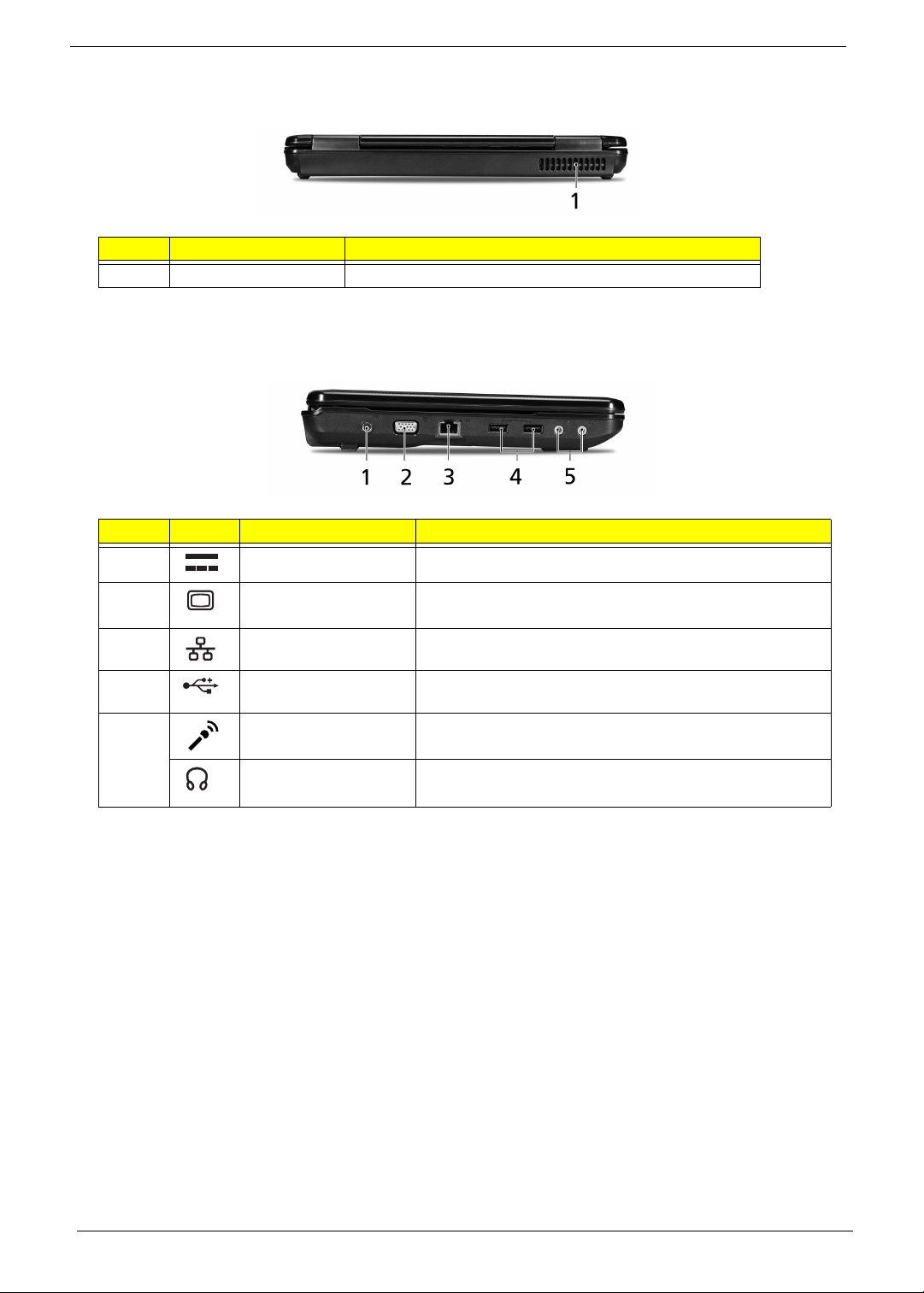
Left View
Item Icon Component Function
1 DC-in jack Connects to the AC adapter.
2 External display (VGA)
port
3 Ethernet port (RJ-45) Connects to an Ethernet 10/100-based network
4 USB 2.0 ports Connect to USB 2.0 devices (e.g., USB mouse, USB
5 Microphone-in jack Accepts inputs from external microphones.
Headphone/speaker/
Line-out jack
Connects to a display device (e.g., external monitor, LCD
projector).
camera).
Connects to audio line-out devices such as speakers, or
headphones.
6 Aspire 4732Z/4332 Service Guide
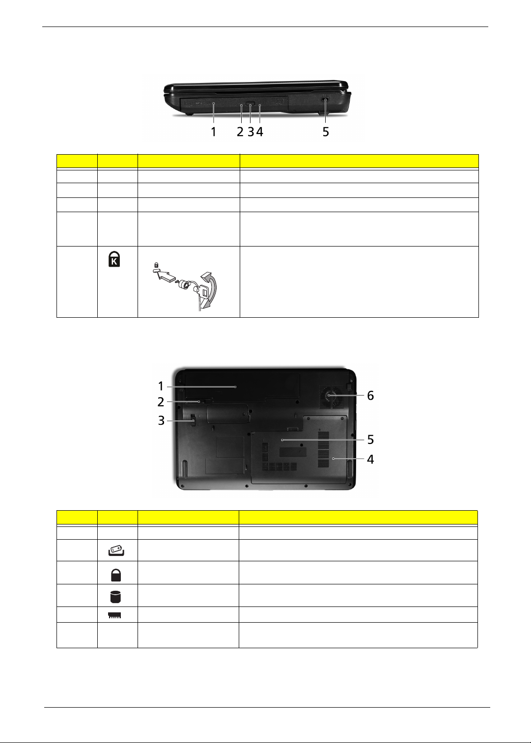
Right View
Item Icon Component Function
1 Optical disc drive (ODD) Internal optical drive; accepts CDs or DVDs.
2 ODD access indicator Lights up when the optical drive is active.
3 ODD eject button Ejects the optical disc from the drive.
4 Emergency eject hole Ejects the optical drive tray when the computer is turned off.
Note: Insert a paper clip to the emergency eject hole to eject
the ODD tray when the computer is off.
5 Kensington lock notch Connects to a Kensington-compatible computer security
lock.
Note: Wrap the computer security lock cable around an
immovable object such as a fixed table or the handle of a
locked drawer. Insert the lock into the notch and turn the key
to secure the lock. Some keyless models are also available.
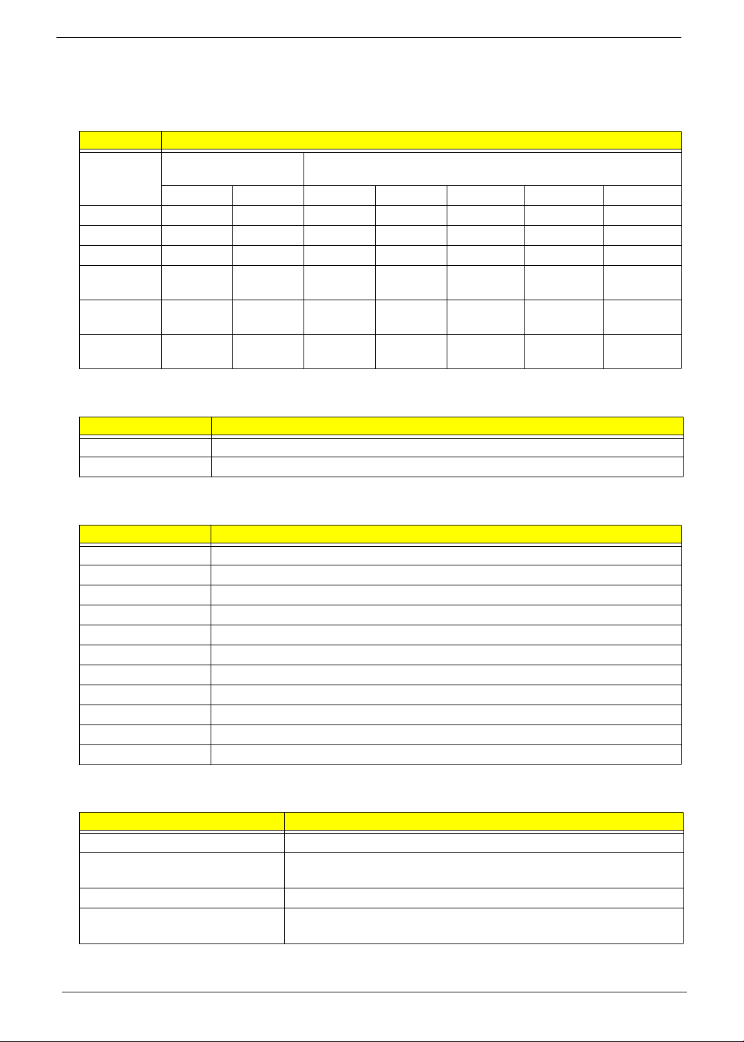
Base View
Item Icon Component Function
1 Battery bay Houses the computer's battery pack.
2 Battery release latch Releases the battery pack for removal.
3 Battery lock Locks the battery pack in position.
4 HDD bay Houses the computer's hard disk.
5 Memory compartment Houses the computer's memory modules.
6 Ventilation slots and
cooling fan
Enable the computer to stay cool, even after prolonged use.
Note: Do not cover or obstruct the fan opening.
Aspire 4732Z/4332 Service Guide 7
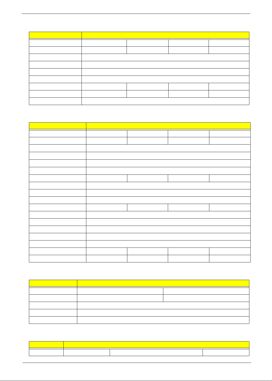
Specifications
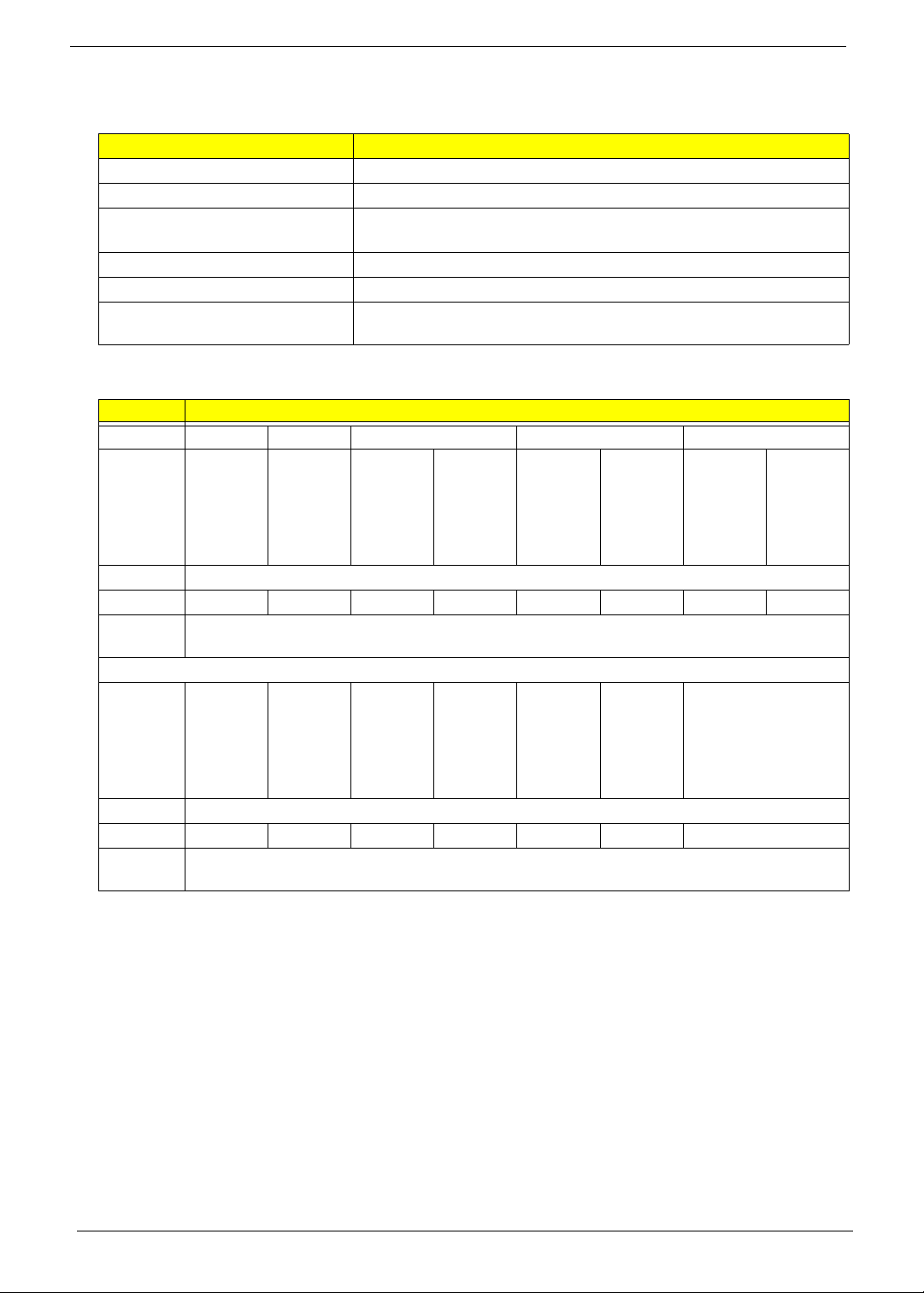
Processor
Item Processors Type
Intel Pentium
Processors for Mobile
T4200 T3400 900 T1600 T1700 575 585
CPU speed 2.0 GHz 2.16 GHz 900 MHz 1.66 GHz 1.83 GHz 2.0 GHz 2.16 GHz
Bus speed 800 MHz 667 MHz 100 MHz 667 MHz 667 MHz 667 MHz 667 MHz
L2 cache 1 MB 1 MB 128 KB 1 MB 1 MB 1 MB 1 MB
Package
type
Core
stepping
Thermal
design power
MicroFCPGA
M0 M0 PD0 M0 M0 M0 M0
35W 35W 24W 35W 35W 31W 31W
MicroFCPGA
MicroPGA2
System Chipsets
Item Specification
North bridge Mobile Intel GL40/GM45 Express Chipset
South bridge 82801IBM I/O Controller Hub (ICH9M)
Mobile Intel Celeron Processors
MicroFCPGA
MicroFCPGA
MicroFCPGA
MicroFCPGA
System Controllers
Item Specification
Hard drive Integrated in the ICH9M
Memory Integrated in the Mobile Intel GL40/GM45 Express Chipset
Video Integrated in the Mobile Intel GL40/GM45 Express Chipset
VGA memory Intel UMA
Audio Conexant HD-Audio SmartAudio 221 (CX20561)
Wireless LAN Intel WiFi Link 512AG_MMW / Atheros XB63 / Broadcom BCM4312
Ethernet Atheros AR8114 PCI-E Ethernet Controller
Modem External USB Lite + LSI modem
Bluetooth (optional) Broadcom Blutonium BCM2045
Keyboard Winbond KBC773L
Card reader Realtek RTS5159
Video
Item Specification
Video controller Integrated in the Mobile Intel GL40 / GM45 Express Chipset
FSB speed GL40: 667 MHz
GM45: 667 MHz / 800 MHz / 1066 MHz
Dual Independent Display support Yes
Graphics output GL40: LVDS, SDVO, TV Out, CRT
GM45: LVDS, SDVO, TV Out, CRT, DVI, HDMI, DisplayPort
8 Aspire 4732Z/4332 Service Guide
Audio
Item Specification
Audio controller Conexant HD-Audio SmartAudio 221 (CX20561)
Features High-definition audio system, MS-Sound compatible, built-in stereo speakers;
microphone-in and line-out jacks
Wireless LAN
Item Specification
Model Intel WiFi Link 512AG_MMW / Atheros XB63 / Broadcom BCM4312
Connector interface Mini Card form factor, based on PCIe electrical interface
IEEE WLAN standard 802.11a/b/g
Ethernet
Item Specification
Ethernet controller Atheros AR8114 PCI-E Ethernet Controller
LAN protocol 10/100 Mbps
LAN connector type RJ-45
Features Onboard Fast Ethernet, Wake on LAN ready
Bluetooth
Item Specification
Model Broadcom Blutonium BCM2045
Versi on Bluetooth 2.0 (backward compatible with 1.1, 1.2)
EDR support Yes
Practical data rate 2.1 Mbit/s
Keyboard
Item Specification
Keyboard controller Winbond KBC773L
Brand Darfon
Features • 86-/87-/91-key EM4T series keyboard with embedded numeric keypad, inverted-T
cursor keys, Internet scroll key, and 12 function keys (hotkeys)
• Multilanguage support
• Spill-proof
Card Reader
Item Specification
Card reader controller Realtek RTS5159
Card compatibility MMC, SD, xD, MS, and MS PRO
Aspire 4732Z/4332 Service Guide 9
Memory
System Memory
Item Specification
Memory controller Integrated in the Mobile Intel GL40/GM45 Express Chipset
Number of DIMM slot 2
Maximum memory size 32-bit OS: 1 GB per slot; 2 GB maximum system memory
64-bit OS: 2 GB per slot; 4 GB maximum system memory
DIMM speed 667 MHz (PC2-5300), 800 MHz (PC2-6400)
DIMM type 200-pin SO-DIMM
Memory module combinations You can install memory modules in any combination as long as they
match the above specifications.
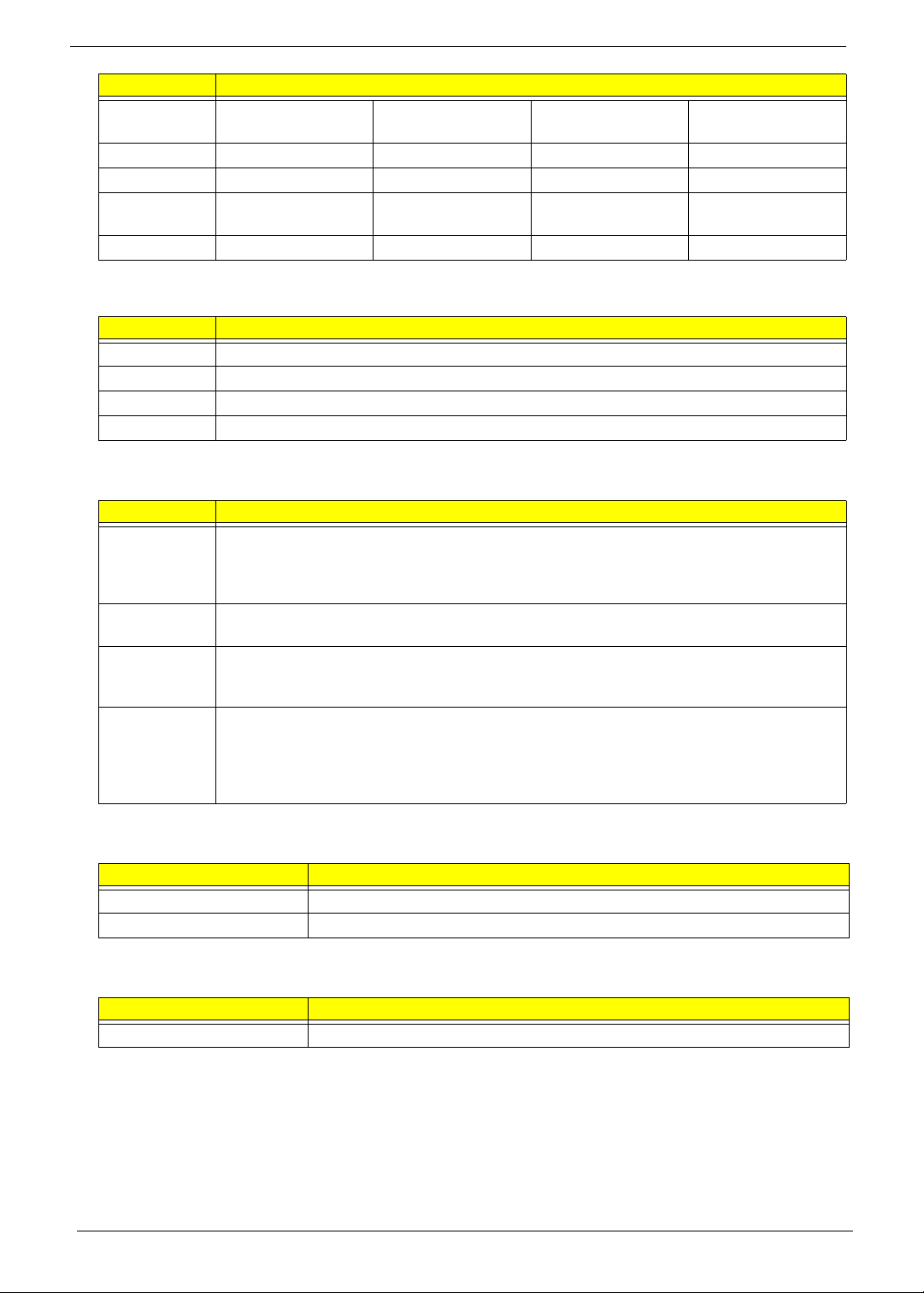
Memory Module
Item Specification
Brand Elpida Hynix Micron Nanya Samsung
Part name EBE11UE
6ACUA6E-E
Density 1 GB
Data rate 667 MHz 667 MHz 667 MHz 800 MHz 667 MHz 800 MHz 667 MHz 800 MHz
RoHS
compliant
Yes
HYMP112
S64CP6Y5 LF
HMP112S
6EFR6CY5
MT8HTF1
2864HDY667
MT8HTF1
2864HDY800
NT1GT64
UH8D0FN
-3C
NT1GT64
UH8D0FN
-AD
M470T28
64EH3CE6
M470T28
64EH3CF7
Part name EBE21UE
8ACUA6E-E LF
Density 2 GB
Data rate 667 MHz 667 MHz 667 MHz 800 MHz 667 MHz 800 MHz 667 MHz
RoHS
compliant
Yes
HYMP125
S64CP8Y5
HMP125S
6EFR8CY5
MT16HTF
25664HY667
MT16HTF
25664HY800G1
NT2GT64
U8HD0B
N-3C
NT2GT64
U8HD0B
N-AD
M470T5663EH3-CE6
10 Aspire 4732Z/4332 Service Guide
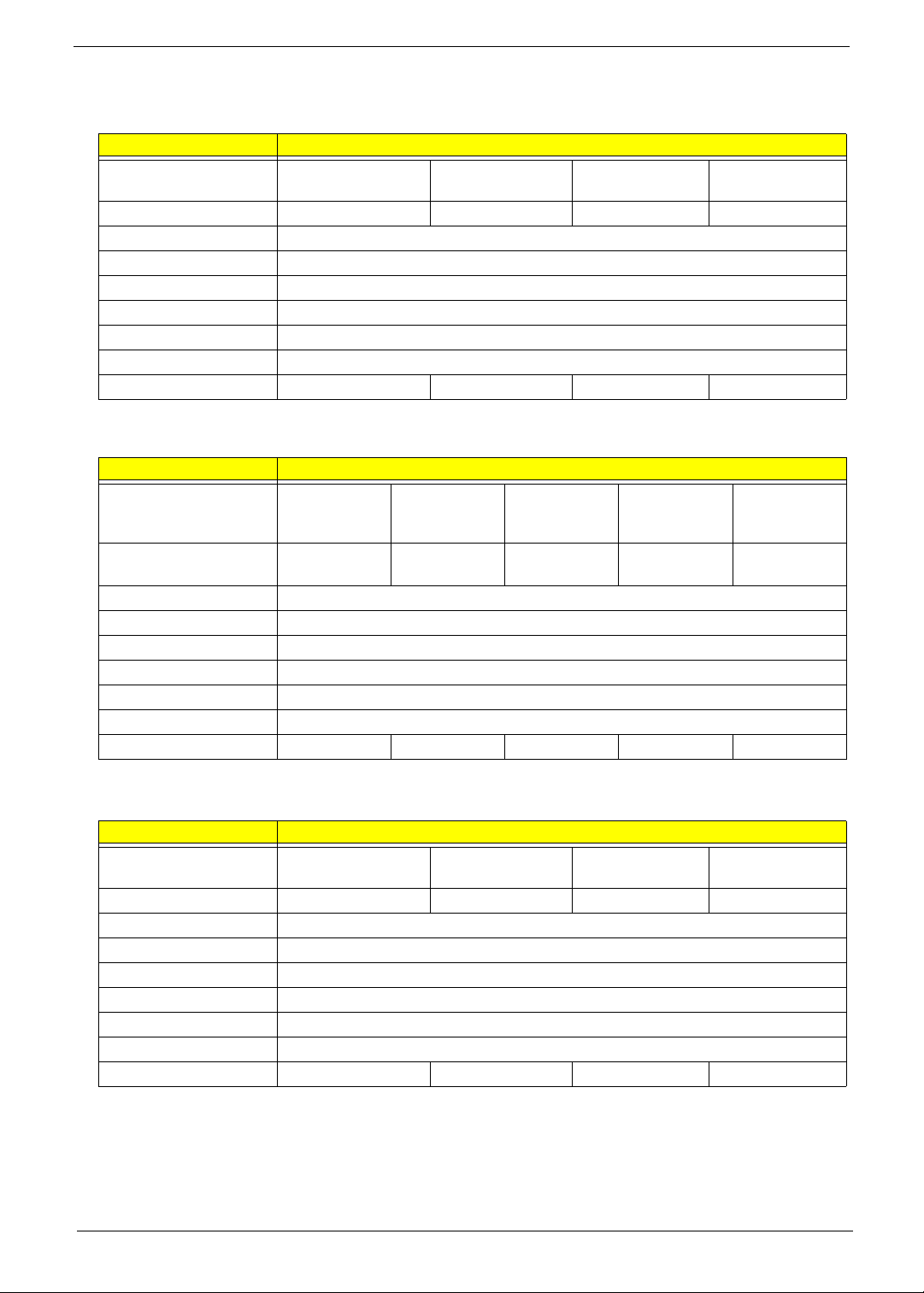
Hard Disk Drive
160-GB HDD
Item Specification
Product HGST Travelstar
5K320
Model HTS543216L9A300 ST9160310AS MK1655GSX WD1600BEVT
Form factor 2.5 inch
Interface SATA 3.0
Sector size (bytes) 512
Data buffer (MB) 8
Rotational speed (RPM) 5400
Interface transfer rate 300 MB/s
Seek time, typical (ms) 12 14 12 12
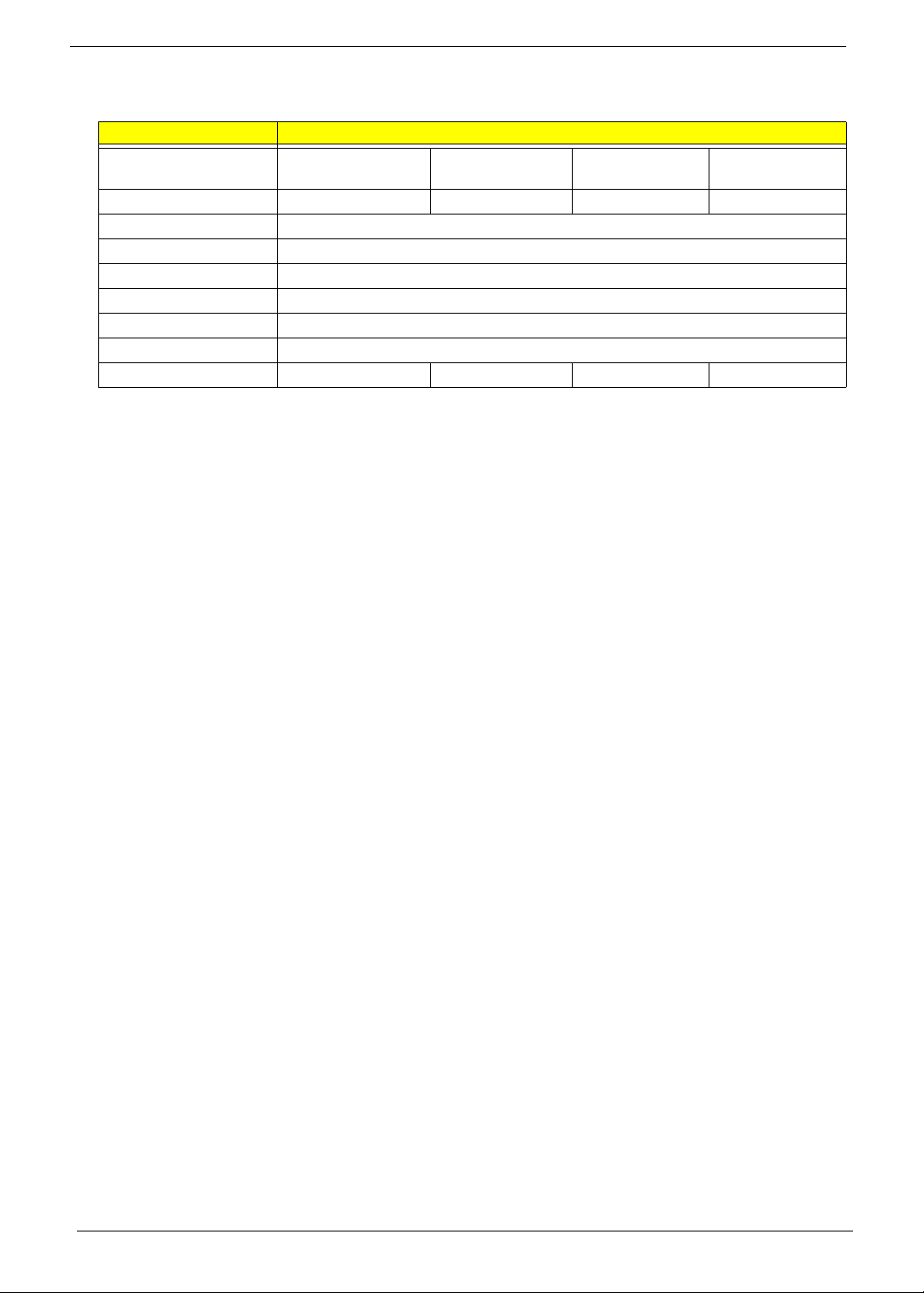
250-GB HDD
Item Specification
Product Hitachi
Travelstar
5K500.B
Model HTS545025B9
A300
Form factor 2.5 inch
Interface SATA 3.0
Sector size (bytes) 512
Data buffer (MB) 8
Rotational speed (RPM) 5400
Interface transfer rate 300 MB/s
Seek time, typical (ms) 12 14 14 12 12
Seagate Momentus
5400.5
Seagate
Momentus
5400.5
ST9250320AS ST9250315AS MK2555GSX WD2500BEVT
Seagate
Momentus
5400.6
To sh i ba
MKxx55GSX
Toshiba
MKxx55GSX
WD Scorpio Blue
WD Scorpio
Blue
320-GB HDD
Item Specification
Product Hitachi Travelstar
5K500.B
Model HTS545032B9A300 ST9320320AS MK3255GSX WD3200BEVT
Form factor 2.5 inch
Interface SATA 3.0
Sector size (bytes) 512
Data buffer (MB) 8
Rotational speed (RPM) 5400
Interface transfer rate 300 MB/s
Seek time, typical (ms) 12 14 12 12
Seagate Momentus
5400.5
To sh i ba
MKxx55GSX
WD Scorpio Blue
Aspire 4732Z/4332 Service Guide 11
500-GB HDD
Item Specification
Product Hitachi Travelstar
5K500.B
Model HTS545050B9A300 ST9500325AS MK5055GSX WD5000BEVT
Form factor 2.5 inch
Interface SATA 3.0
Sector size (bytes) 512
Data buffer (MB) 8
Rotational speed (RPM) 5400
Interface transfer rate 300 MB/s
Seek time, typical (ms) 12 14 12 12
Seagate Momentus
5400.6
To sh i ba
MKxx55GSX
WD Scorpio Blue
12 Aspire 4732Z/4332 Service Guide
Optical Disc Drive
Item Specification
Brand LG Panasonic PLDS Sony NEC
Model GT 20N UJ880A DS-8A3S Optiarc AD-7580S
Drive type Super Multi Slim DVD Rewriter
Write/read speed 8x
Temperature, operating 5 to 50 °C
Tray height (mm)) 12.7
Dimension (W x D, mm) 128 × 127 128 × 129 128 × 126.1 128 × 129
Weight (g) 168 175 170 160
Interface SATA
LCD Panel
Item Specification
Brand AUO CMO LG Display Samsung
Model B140XW01 N140B6 LP140WH1 LTN140AT01
Screen size (diagonal, inch)
Display area
Type
Brightness (nits)
View angle (U/D/R/L) 15/35/45/45 20/45/45/45 60/60/70/70 45/45/15/30
Backlight LED
Display resolution (pixels) 1366×768
Number of colors 262K
Contrast ratio 500:1 600:1 600:1 500:1
Aspect ratio 16:9
Response time (ms) 8
Optical coating Anti-glare
Interface LVDS
Supply voltage (v) 3.3
Outline dimensions (mm) 324 × 192.5 × 5.2 324 × 192.5 × 5.2 324 × 192.5 × 5.5 323.5 × 192 × 5.2
Weight (g) 340 340 340 350
14
309.399mm(H) X 173.952mm(V) (14.0” diagonal)
Wide XGA
220
Webcam
Item Specification
Brand Chicony Suyin
Model Calla Camellia
Resolution 0.3M
Lens 2G
DV capability Ye s
AC Adapter
Item Specification
Brand Delta Hipro Lite-On
Aspire 4732Z/4332 Service Guide 13
Item Specification
Model SADP-65KB DFJ
ADP-65JH DB A
Output rating 19 V 19.5 V 19 V 19 V
Output power 65 W 65 W 90 W 65 W
Input voltage
(Vac)
Input frequency 50–60 Hz 47–63 Hz 47–63 Hz 50–60 Hz
100–240 90–264 90–264 100–240
HP-OK065B13 HP-A0652R3B PA-1650-02AC
PA-1650-22AC
Battery Pack
Item Specification
Brand Panasonic, Samsung, Sanyo, Simplo, Sony
Capacity 4400 mAh
Pack capacity 6 cells, 2.0 mAh
Type Lithium-ion, 3S2P
Power Management
ACPI mode Description
G3 • Mechanical Off - All devices in the system are turned off completely. No electrical current is
running through the system. Except for the real-time clock, power consumption is zero. The
machine can be worked on without damaging the hardware or endangering service
personnel.
G2/S5 • Soft Off - The computer consumes a minimal amount of power. No user mode or system
mode code is run. It is not safe to disassemble the machine in this state.
G1 • Sleeping - The computer consumes a small amount of power, user mode threads are not
being executed, and the system “appears” to be off (from the end user’s perspective, the
display is off, and so on). It is not safe to disassemble the machine in this state.
G0 • Working - The system dispatches user mode (application) threads and they execute. In this
state, peripheral devices are having their power state changed dynamically. The user can
select, through some UI, various performance/power characteristics of the system to have
the software optimize for performance or battery life. The system responds to external events
in real time. It is not safe to disassemble the machine in this state.
BIOS
Item Specification
BIOS chip Winbond W25X16
Setup utility Phoenix SecureCore Setup Utility
Antivirus Protection
Item Specification
Product Norton Internet Security 2009 (v16.0)
14 Aspire 4732Z/4332 Service Guide

Chapter 2
System Utilities
Phoenix SecureCore Setup Utility
Phoenix SecureCore Setup Utility is a hardware configuration program built into your system's Basic Input/
Output System (BIOS). Since most systems are already properly configured and optimized, there is normally
no need to run this utility.
You will need to run this utility under the following conditions:
• When changing the system configuration including:
• Setting the system time and date
• Configuring the hard drives
• Specifying the boot device sequence
• Configuring the power management modes
• Setting up system passwords or making other changes to the security setup
• When a configuration error is detected by the system and you are prompted ("Run Setup" message) to
make changes to the BIOS settings.
IMPORTANT: If you repeatedly receive “Run Setup” messages, the RTC battery located on the mainboard
(RTC1) may be defective. In this case, the system cannot retain configuration values in CMOS.
Replace the RTC battery with a new one.
NOTE: For ease of reading, Phoenix SecureCore Setup Utility will be simply referred to as “Setup” or “Setup
Utility” in this Service Guide.
In the descriptive tables following each of the menu screen illustrations, settings in boldface are the
default and suggested parameter settings.
The Setup Utility loads the configuration values in a battery-backed nonvolatile memory called CMOS RAM.
This memory area is not part of the system RAM, which allows configuration data to be retained when power is
turned off. The values take effect when the system is booted. POST uses these values to configure the
hardware. If the values and the actual hardware do not agree, POST generates an error message. You must
run this utility to change the BIOS settings from the default or current configuration.
Aspire 4732Z/4332 Service Guide 15
Accessing the Setup Utility
1. Turn on the computer.
If the computer is already turned on, save your data and close all open applications, then restart the
computer.
2. During POST, press F2.
If you fail to press F2 before POST is completed, you will need to restart the computer. Use the left ( )
and right ( ) arrow keys to move between selections on the menu bar.
Information Security Boot Exit
CPU Type:
CPU Speed:
IDE0 Model Name:
I D E 0 Se ri al N um be r:
ATAPI Model Name:
System BIOS Version:
VGA BIOS Version:
KBC Version:
Serial Number:
Asset Tag Number:
Product Name:
Manufacturer Name:
UUID:
Phoenix SecureCore(tm) Setup Utility
Main
Intel (R) Core (TM)2 Duo CPU T6400 @ 2.00 GHz
2.00GHz
XXXXXXXXXXX-(XX)
XXXXXXXX
XXXXXXXXXXX-XXX XX-XXXX-(XX)
VX.XX
XX-XXX XXXXXX.XXX.XXX.XXX.XXXXXX
XX.XX
XXXXXXXXXXXXXXXXXXXXXXX
None
Aspire 5738
Acer
XXXxXxXX-xXxX-XXxx-xXXx-xXXxXXxXxxXX
Menu bar
F1
Esc
Help
Exit
Select Item
Select Menu
Change Values
-/+
Select Sub-Menu
Enter
Setup Defaults
F9
S a v e an d Ex it
F10
Legend bar
16 Aspire 4732Z/4332 Service Guide
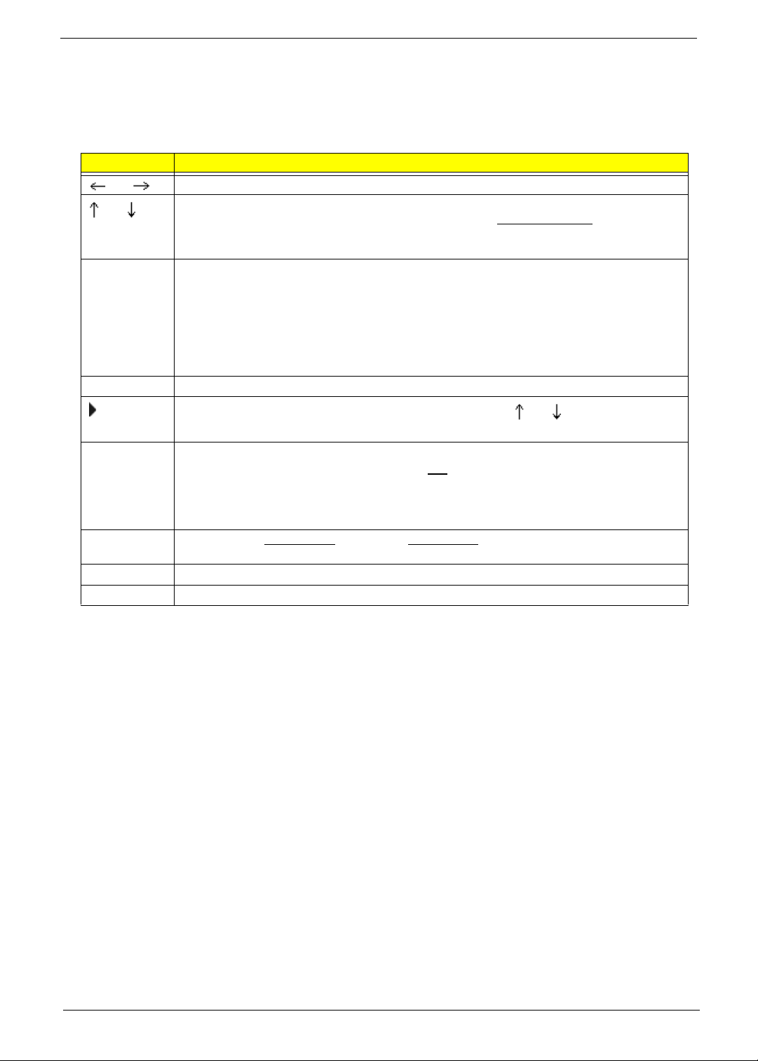
Navigating through the Setup Utility
Use the keys listed in the legend bar on the bottom of the Setup screen to work your way through the various
menu and submenu screens of the Setup Utility. The table below lists these legend keys and their respective
functions.
Key Function
and
F5 and F6 To select a value for the currently selected field (only if it is user-configurable). Press these
Enter To select a field value (a pop-up menu displays) or submenu screen.
Esc If you press this key:
F1 or Alt-H To bring up the General Help window. The General Help window describes other Setup
F9 Press to load default system values.
F10 Press to save changes and close the Setup Utility.
and To move between selections on the menu bar.
To move the cursor to the field you want.The currently selected field will be highlighted. The
right side of each menu screen displays a field help panel—
panel displays the help text for the currently selected field. It updates as you move the cursor to
each field.
keys repeatedly to display all possible entries. A parameter that is enclosed in square brackets
[ ] is user-configurable. Grayed-out parameters are not user-configurable for one of the
following reasons:
q The field value is auto-configured or auto-detected.·
q The field value is informational only.
q The field is password-protected.
Indicates a submenu field. To view a submenu screen, use the and keys to move the
cursor to the submenu you want, then press Enter.
q On one of the primary menu screens, the Exit menu displays.
q On a submenu screen, the previous screen displays.
q When you are making selections from a pop-up menu, closes the pop-up without making a
selection.
navigation keys that are not displayed on the legend bar.
Item Specific Help panel. This
Setup Utility Menus
The Setup Utility has five menus for configuring the various system functions. These include:
• Information
•Main
• Security
• Boot
• Exit
NOTE: The screenshots used in this section are for illustration only. The values displayed may not be the
same as those in your computer.
Aspire 4732Z/4332 Service Guide 17
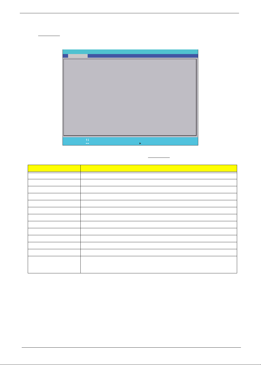
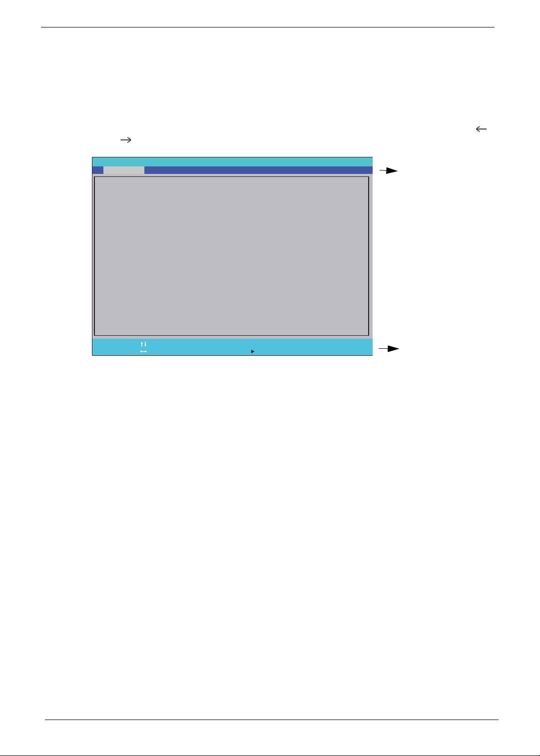
Information
The Information menu screen displays a summary of your computer hardware information. These information
are necessary for troubleshooting and may be required when asking for technical support.
Information Security Boot Exit
CPU Type:
CPU Speed:
IDE0 Model Name:
I D E 0 Se ri al N um be r:
ATAPI Model Name:
System BIOS Version:
VGA BIOS Version:
KBC Version:
Serial Number:
Asset Tag Number:
Product Name:
Manufacturer Name:
UUID:
Help
F1
Exit
Esc
Phoenix SecureCore(tm) Setup Utility
Main
Intel (R) Core (TM)2 Duo CPU T6400 @ 2.00 GHz
2.00GHz
XXXXXXXXXXX-(XX)
XXXXXXXX
XXXXXXXXXXX-XXX XX-XXXX-(XX)
VX.XX
XX-XXX XXXXXX.XXX.XXX.XXX.XXXXXX
XX.XX
XXXXXXXXXXXXXXXXXXXXXXX
None
Aspire 5738
Acer
XXXxXxXX-xXxX-XXxx-xXXx-xXXxXXxXxxXX
Select Item
Select Menu
Change Values
-/+
Select Sub-Menu
Enter
Setup Defaults
F9
S a v e an d Ex it
F10
The following table describes the information displayed in the Information menu screen.
Field Description
CPU Type Displays the processor model.
CPU Speed Displays the processor speed.
IDE0 Model Name Displays the model name of the hard drive installed on the primary IDE master.
IDE0 Serial Number Displays the serial number of the hard drive installed on the primary IDE master.
ATAPI Model Name Displays the model name of the optical disc drive installed in the system.
System BIOS Version Displays the current system BIOS version.
VGA BIOS Version Displays the current VGA BIOS version.
KBC Version Displays the keyboard controller version.
Serial Number Displays the system serial number.
Asset Tag Number Displays the system asset tag number
Product Name Displays the official model name of the computer.
Manufacturer Name Displays the manufacturer of the computer.
UUID Displays your computer’s UUID (universally unique identifier). UUID is an identifier
standard used in software construction, standardized by the Open Software
Foundation (OSF) as part of the Distributed Computing Environment (DCE).
18 Aspire 4732Z/4332 Service Guide
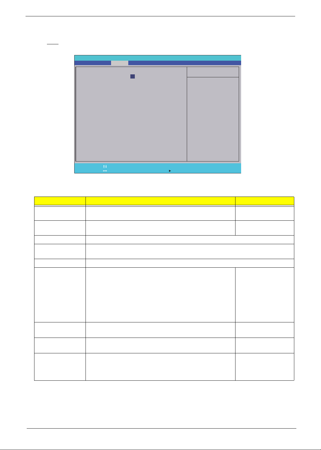
Main
The Main menu screen allows you to configure the basic system settings.
Information Security
System Time:
System Date:
System Memory:
Extended Memory:
Video Memory:
Quiet Boot:
Network Boot:
F12 Boot Menu:
D2D Recovery:
SATAMode
Help
F1
Exit
Esc
Phoenix SecureCore(tm) Setup Utility
Main
[]
10
[]
03/05/2009
632 KB
4093 MB
512 MB
[Enabled]
[Enabled]
[Disabled]
[Enabled]
[AHCI]
Select Item
Select Menu
:10:10
-/+
Enter
Boot
Change Values
Select Sub-Menu
Exit
Item Specific Help
<Tab>, <Shift-Tab>, or
<Enter> selects field.
Setup Defaults
F9
S a v e an d Ex it
F10
The following table describes the parameters in this screen.
Field Description Value
System Time Sets the system time. HH:MM:SS
(hour:minute:second)
System Date Sets the system date. MM/DD/YYYY
(month/day/year)
System Memory Displays the size of system memory detected during boot-up.
Extended Memory Displays the size of extended memory detected during boot-up. Extended memory = Total
memory –1MB
Video Memory Displays the size of video memory detected during boot-up.
Quiet Boot Enables or disables the Quiet Boot function.
When enabled, BIOS setup is in graphical mode and displays
Disabled
Enabled
only an identification logo during POST and while booting. After
booting, the screen displays the operating system prompt (such
as DOS) or logo (such as Windows 95). If any error occurs while
booting, the system automatically switches to text mode.
When disabled, BIOS setup is in the conventional text mode
where you see the system initialization details on the screen.
Network Boot When enabled, a remote host with appropriate boot image can
boot this computer. (only works with an Ethernet device.)
Disabled
Enabled
F12 Boot Menu Enables or disables the Boot menu during POST. Disabled
Enabled
D2D Recovery Enables or disables D2D Recovery function. This function
allows the user to create a hidden partition on the hard drive to
Disabled
Enabled
store the operation system. User can then use this partition to
restore the system to factory defaults.
Aspire 4732Z/4332 Service Guide 19
Field Description Value
SATA Mode Select the SATA controller operating mode.
When set to AHCI (Advanced Host Controller Interface), the
AHCI
IDE
SATA controller enables its AHCI and RAID features when the
computer boots up.
When set to IDE, the SATA controller disables its AHCI and
RAID functions when the computer boots up.
NOTE: The Acer eMachine D525/D725 computer does not
support AHCI or RAID functions so set this parameter to IDE to
speed up the boot-up time.
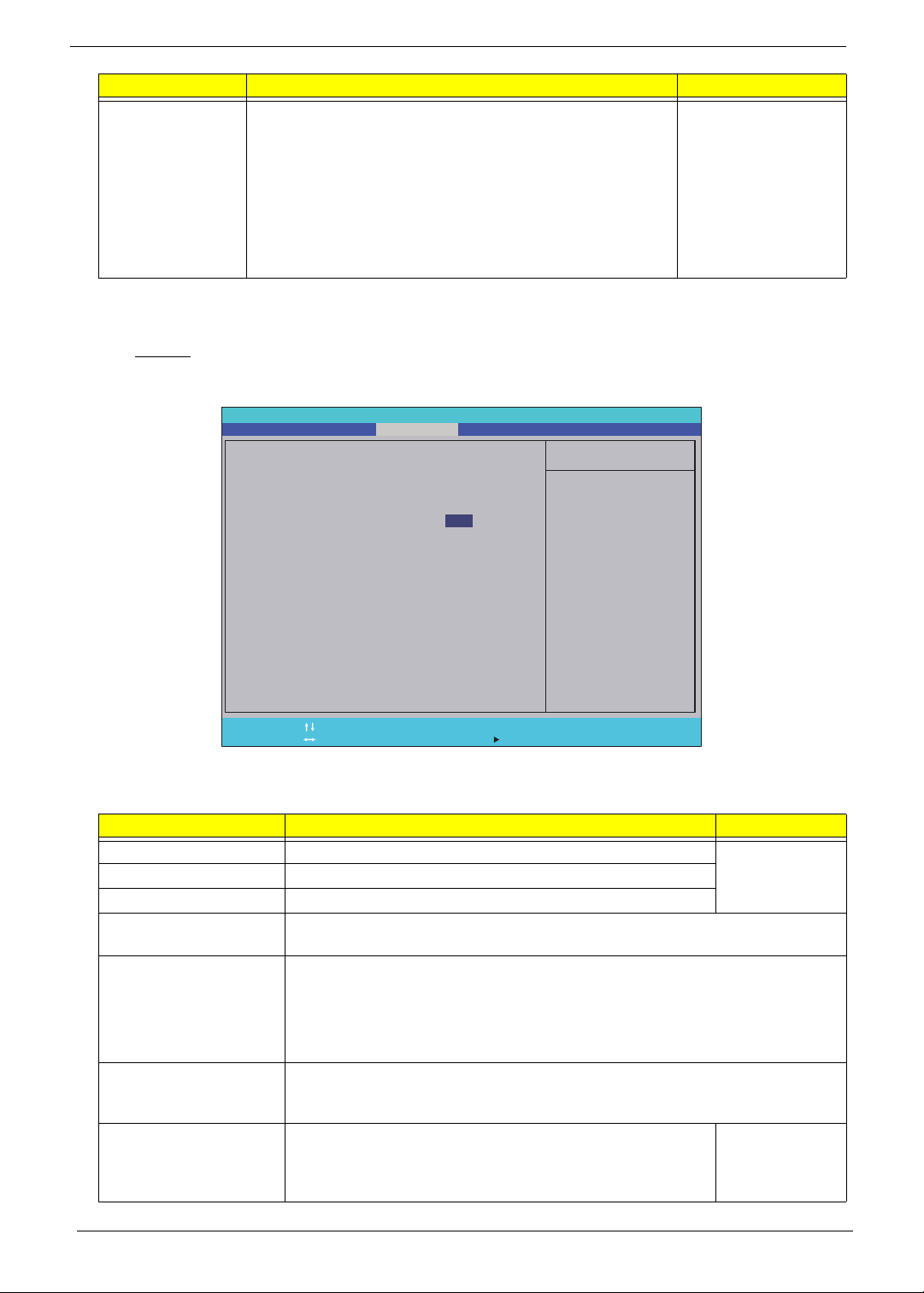
Security
The Security menu screen contains parameters that help safeguard and protect your computer from
unauthorized use.
Information Security Boot Exit
Supervisor Password s:
User Password s:
H D D P as sw or d is
Set Supervisor Password
S e t U se r Pa ss wo rd
Set Password
HDD
P a s sw or d on B oo t:
Help
F1
Exit
Esc
Phoenix SecureCore(tm) Setup Utility
Main
i
i
:
Select Item
Select Menu
Clear
Clear
Clear
[]Enter
[Enter]
[Enter]
[Disabled]
Change Values
-/+
Select Sub-Menu
Enter
Item Specific Help
Supervisor Password
c o n tr ol s ac ce ss o f th e
whole setup utility.
I t c a n be u se d to b oo t
u p w h en P as sw or d on
boot is enabled.
Setup Defaults
F9
S a v e an d Ex it
F10
The following table describes the parameters in the Security menu screen.
Field Description Value
Supervisor Password is Displays the supervisor password status. Clear
User Password is Displays the user password status.
Set
HDD Password is Displays the HDD password status.
Set Supervisor
Password
Press Enter to configure the supervisor password. When set, this password will
allow the user to access and change all settings in the Setup Utility.
Set User Password Press Enter to configure the user password. When set, this password will restrict a
user’s access to the Setup menus. Only the following menus will be accessible:
• System Time and System Date
• All Exit menu options excluding Load Setup Defaults
A supervisor password must first be set before creating this user password.
Set HDD Password Press Enter to configure the HDD password. When set, this password will restrict a
user’s access to the hard disk drive. It will be required during boot-up or when
waking from hibernation mode.
Password on Boot Referred to as power-on password. When set, the user or
supervisor password will be required to boot up the system. A
Disabled
Enabled
supervisor password must first be set before creating this
password.
20 Aspire 4732Z/4332 Service Guide
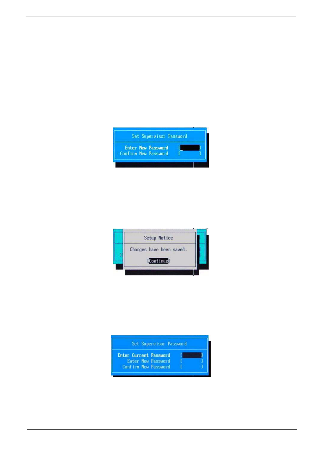
Setting a system password
Note the following before you define a system password:
• The maximum length of password contains 8 alphanumeric characters—A - Z, 0 - 9, and ‘;’
(for French keyboard).
• System passwords are case-insensitive.
• When you are prompted to enter a password, you have three tries before the system halts. Do not forget
your password. If you forget your password, you may have to return your computer to your dealer to reset
it.
To set a system password:
1. Select a password parameter, then press Enter.
The password box appears.
2. Type a password then press Enter.
IMPORTANT: Be very careful when typing your password because the characters do not appear on the
screen. Only shaded blocks representing each typed character are visible.
3. Retype the password to verify the first entry, then press Enter.
You will be prompted to save the new password.
4. Press Enter.
5. Press F10 to save the password and close the Setup Utility.
To change a system password:
1. Select a password parameter, then press Enter.
The password box appears.
2. Type the original password, then press Enter.
3. Type a new password, then press Enter.
Aspire 4732Z/4332 Service Guide 21
4. Retype the new password to verify the first entry, then press Enter.
You will be prompted to save the new password.
5. Press Enter.
6. Press F10 to save the password and close the Setup Utility.
To remove a system password:
1. Select a password parameter, then press Enter.
The password box appears.
2. Type the original password, then press Enter.
3. Press Enter twice without entering anything in the new and confirm password fields.
You will be prompted to confirm the password removal.
4. Press Enter.
5. Press F10 to save the changes you made and close the Setup Utility.
Resetting a system password:
If you have forgotten the user password, the computer will continue to function normally but you will have
limited access to the Setup Utility.
If you have enabled the Password on Boot field and you forget the supervisor password, you will not be able to
boot up the computer. The same thing applies if you forget the HDD password.
To clear a lost BIOS password (user or supervisor password) you need to short the G61 hardware gap located
near the processor socket (U33). Go to page
To regain access to your computer if you lose the HDD password, you need to generate a master password
and unlock your hard drive. Go to page
70 for instructions.
71 for instructions.
22 Aspire 4732Z/4332 Service Guide
 Loading...