

Page 1

Acer Altos G540 M2
Series
User’s Guide
Page 2

Copyright © 2009 Acer Incorporated
All Rights Reserved.
Acer Altos G540 M2 Series
User’s Guide
Changes may be made periodically to the information in this publication without obligation
to notify any person of such revision or changes. Such changes will be incorporated in new
editions of this manual or supplementary documents and publications. This company makes
no representations or warranties, either expressed or implied, with respect to the contents
hereof and specifically disclaims the implied warranties of merchantability or fitness for a
particular purpose.
Record the model number, serial number, purchase date, and place of purchase information in
the space provided below. The serial number and model number are recorded on the label
affixed to the unit. All correspondence concerning the unit should include these information.
No part of this publication may be reproduced, stored in a retrieval system, or transmitted, in
any form or by any means, electronic, mechanical, photocopy, recording, or otherwise,
without the prior written permission of Acer Incorporated.
Acer Altos G540 M2 Series
Model Name :
G540 M2
Part Number: MU.R3500.001
Purchase Date:
Place of Purchase:
Acer and the Acer logo are registered trademarks of Acer Inc. Other company’s product
names or trademarks are used herein for identification purposes only and belong to their
respective companies.
Page 3

iii
Notices
FCC notice
Class A devices do not have an FCC logo or FCC IDE on the label. Class B devices
have an FCC logo or FCC IDE on the label. Once the class of the device is
determined, refer to the following corresponding statement.
Class A equipment
This device has been tested and found to comply with the limits for a Class A
digital device pursuant to Part 15 of the FCC Rules. These limits are designed to
provide reasonable protection against harmful interference when the
equipment is operated in a commercial environment. This equipment
generates, uses, and can radiate radio frequency energy, and if not installed
and used in accordance with the instructions, may cause harmful interference to
radio communications. Operation of this equipment in a residential area is
likely to cause harmful interference, in which case the user will be required to
correct the interference at personal expense.
Notice: Shielded cables
All connections to other computing devices must be made using shielded cables
to maintain compliance with FCC regulations.
Notice: Peripheral devices
Only peripherals (input/output devices, terminals, printers, etc.) certified to
comply with the Class A limits may be attached to this equipment. Operation
with noncertified peripherals is likely to result in interference to radio and TV
reception.
Caution: Changes or modifications not expressly approved by the
manufacturer could void the user’s authority, which is granted by
the Federal Communications Commission, to operate this server.
Page 4

iv
Use conditions
This part complies with Part 15 of the FCC Rules. Operation is subject to the
following two conditions: (1) this device may not cause harmful interference,
and (2) this device must accept any interference received, including interference
that may cause undesired operation.
Notice: Canadian users
This Class A digital apparatus meets all requirements of the Canadian
interference-Causing Equipment Regulations.
Laser compliance statement
The CD-ROM drive in this server is a laser product. The CD-ROM drive’s
classification label (shown below) is located on the drive.
CLASS 1 LASER PRODUCT
CAUTION: INVISIBLE LASER RADIATION WHEN OPEN. AVOID EXPOSURE TO
BEAM.
Page 5

Important safety instructions
Read these instructions carefully. Save these instructions for future reference.
1 Follow all warnings and instructions marked on the product.
2 Unplug this product from the wall outlet before cleaning. Do not use
liquid cleaners or aerosol cleaners. Use a damp cloth for cleaning.
3 Do not use this product near water.
4 Do not place this product on an unstable cart, stand, or table. The product
may fall, causing serious damage to the product.
5 Slots and openings on the front and rear side of the chassis are provided
for ventilation; to ensure reliable operation of the product and to protect
it from overheating, these openings must not be blocked or covered. The
openings should never be blocked by placing the product on a bed, sofa,
rug, or other similar surface. This product should never be placed near or
over a radiator or heat register, or in a built-in installation unless proper
ventilation is provided.
6 This product should be operated from the type of power indicated on the
marking label. If you are not sure of the type of power available, consult
your dealer or local power company.
7 Do not allow anything to rest on the power cord. Do not locate this
product where persons will walk on the cord.
8 If an extension cord is used with this product, make sure that the total
ampere rating of the equipment plugged into the extension cord does not
exceed the extension cord ampere rating. Also, make sure that the total
rating of all products plugged into the wall outlet does not exceed the fuse
rating.
9 Never push objects of any kind into this product through chassis slots as
they may touch dangerous voltage points or short out parts that could
result in a fire or electric shock. Never spill liquid of any kind on the
product.
10 Do not attempt to service this product yourself, as opening or removing
covers may expose you to dangerous voltage points or other risks. Refer all
servicing to qualified service personnel.
v
Page 6

vi
11 Unplug this product from the wall outlet and refer servicing to qualified
service personnel under the following conditions:
a When the power cord or plug is damaged or frayed.
b If liquid has been spilled on the product.
c If the product has been exposed to rain or water.
d If the product does not operate normally when the operating
instructions are followed. Adjust only those controls that are covered
by the operating instructions since improper adjustment of other
controls may result in damage and will often require extensive work
by a qualified technician to restore the product to normal condition.
e If the product has been dropped or the chassis has been damaged.
f If the product exhibits a distinct change in performance, indicating a
need for service.
12 Replace the battery with the same type as the product's battery we
recommend. Use of another battery may present a risk of fire or explosion.
Refer battery replacement to a qualified service technician.
13 Warning! Batteries may explode if not handled properly. Do not
disassemble or dispose of them in fire. Keep batteries away from children.
Promptly dispose used batteries according to regulations applicable to
your area.
14 Use only the proper type of power supply cord set (provided in your
accessories box) for this unit. It should be a detachable type: UL listed/CSA
certified, type SPT-2, rated 7A 125V minimum, VDE approved or its
equivalent. Maximum length is 15 feet (4.6 meters).
Page 7

1 System tour 1
System specifications 3
Performance 3
Mechanical 6
Environmental 6
Hardware options 7
External and internal structure 9
Front bezel 9
Front panel 10
Rear panel 13
Internal components 15
System boards 16
Mainboard 16
Backplane board 21
System LED indicators 24
Front panel LED indicators 24
Hot-plug HDD LED indicator 26
Gigabit LAN port LED indicators 27
2 System setup 29
Setting up the system 31
Pre-installation requirements 31
Connecting peripherals 32
Turning on the system 33
Power-on problems 34
Configuring the system OS 36
Rack mount configuration 37
Turning off the system 38
Contents
3 System upgrade 39
Installation precautions 41
ESD precautions 41
Pre-installation instructions 42
Post-installation instructions 42
Opening the server 43
Removing the side panel 43
Removing the front bezel 44
Configuring the hard drive 45
Installing a 3.5“HDD cage 45
Removing a HDD cage 48
Installing a 2.5“HDD cage 50
Removing a HDD cage 53
Page 8

viii
Installing an additional hard drive 55
Configuring a 5-25 inch storage device 64
Upgrading the processor 70
Upgrading the system memory 78
Installing an expansion card 88
Installing the TPM module 91
Installing the System Fan module 92
Installing a redundant power supply module 94
4 System BIOS 97
BIOS overview 99
Entering BIOS setup 100
BIOS setup primary menus 100
BIOS setup navigation keys 101
Main menu 102
Advanced menu 103
Processor Configuration 104
Advanced Memory Configuration 110
Advanced Chipset Control 112
PCI Configuration 116
SATA Configuration 118
I/O Device Configuration 119
Boot Configuration 120
Thermal and Acoustic Configuration 121
Power 123
Security menu 125
Setting a system password 126
Changing a system password 127
Removing a system password 127
Server menu 128
System Management 129
Console Redirection 130
Event Log Configuration 131
Boot menu 133
Exit menu 134
5 System
troubleshooting 135
Resetting the system 137
Initial system startup problems 138
Initial troubleshooting checklist 139
Hardware diagnostic testing 140
Checking the boot-up status 140
Page 9

Verifying the condition of the storage devices 141
Confirming loading of the operating system 141
Specific problems and corrective actions 142
Appendix A: Server
management tools 147
Server management overview 149
RAID configuration utilities 150
Onboard SATA RAID Configuration Utility 150
LSI MegaRAID SAS 8708EM2 RAID Configuration Utility153
LSI MegaRAID SAS 8204ELP RAID Configuration Utility154
Appendix B: Rack mount configuration 157
Rack installation information 159
Rack installation precautions 159
System rack installation 161
Vertical mounting hole pattern 162
Installing the system into the rack 163
Appendix C: Altos eXpress Console 171
Using Your Altos eXpress Console 173
Software Installation 175
Prerequisites on remote management PC 175
Installing the Java Tool 175
Installing the UPnP tool 176
Using the UPnP tool to search for an Altos server 177
Altos eXpress Console 179
Accessing the Altos eXpress Console 179
Altos eXpress Console User Interface 181
System Status 182
System Information 183
Server Health 185
Configuration 187
Remote Control 200
Maintenance 203
KVM Remote Console Utility 205
Menu bar 207
ix
Index 211
Page 10

x
Page 11

1 System tour
Page 12

The Acer Altos G540 M2 server is a fully
modular dual-processor system featuring the
latest in computing technology. It host a range
of powerful and flexible features designed to
meet the needs of various network
environments. From simple networking
functions to computing intensive applications,
the Altos G540 M2 delivers.
Page 13

System specifications
This section lists down the impressive computing features of the
Altos G540 M2 system.
Performance
Processor
• One or two Intel® Xeon™ processor 5500 series
• Up to 2.93 GHz
• 4.80/5.86/6.40 GT/s QPI
• 4/8 MB shared cache
• 800/1066/1333 DDR3 memory
• Support for the following Intel
• Turbo Boost Technology
• Hyper-Threading (HT) Technology
• Virtualization Technology
• QuickPath Technology up to 6.4 GT/s
• 64 Technology
®
technologies:
1
3
Chipset
•Intel® 5520 chipset
Memory
• Twelve DDR3 1333 MHz ECC unbuffered/registered DIMMs (six
DIMMs per processor), supporting:
• Six-channel memory bus (three channels per processor)
• 1 to 8 GB (subject to availability) registered DIMMs for up to
96 GB of total system memory, or 1 to 4 GB unbuffered DIMMs
for up to 48 GB of total system memory
• Memory mirroring, Lockstep mode, x4/x8 SDDC
1
For more information on these Intel technologies, visit the Intel Xeon web
site at http://www.intel.com/products/processor/xeon/index.htm
.
Page 14

4
1 System tour
PCI interface
• Five PCI Express® and PCI expansion slots
• One PCI Express® 2.0 x16 slot
• Two PCI Express® 2.0 x8 slots (with eight PCI Express® 2.0
lanes)
• One PCI Express® x8 slot (with four PCI Express® lanes)
• One PCI (32-bit / 3.3 V) slot
Video controller
• Embedded graphics controller with 32 MB video memory
Networking
• Integrated dual-port Gigabit Ethernet supporting Intel® I/O
Acceleration Technology (IOAT)
• Integrated single-port 10/100 Fast Ethernet for server
management and KVM over IP remote management
• Supports boot from iSCSI
Media storage
Two front 5.25” drive bays:
• Up to eight 3.5" or sixteen 2.5" SAS/SATA HDDs in two cages
• Easy-swappable
• Supports hot-swap with optional backplane
Note: 3.5” and 2.5” drives cannot be combined together,
either you have to all use the 3.5” drive or all 2.5” drive.
Combination of the two different sized drive is not
supported.
• DVD-ROM or DVD Writer
• 5.25" tape drive (optional)
Page 15

I/O ports
5
• Two PS/2 ports
• Serial port
• VGA port
• Six USB 2.0 ports
• Two Gigabit LAN ports (RJ-
45)
• Fast Ethernet (RJ-45) port
dedicated for BMC for
management
Power supply and system fan
• 600 W (85% power efficiency) or 610 W power supply, 110-127 /
200-240V (can be upgraded with second power module for hotswap and redundancy)
• One system fan (can be upgraded with second system fan for
redundancy)
Hardware monitoring and server management
• Power status LED
• HDD access LED
• LAN activity LED
• System Status LED
• System ID LED/Button
• Chassis intrusion alert
• Lockable door
• IPMI 2.0
• TPM v1.2
• Built-in Altos eXpress Console for server management and KVM
over IP remote management
• Acer EasyBUILD™v9.0
• Acer Server Manager (ASM)
Operating system
• Microsoft® Windows® Server 2008 Standard and Enterprise
Edition (x86)
• Microsoft® Windows® Server 2008 Standard and Enterprise
Edition (EM64T)
Page 16

6
• Microsoft® Windows® Server 2003 Standard and Enterprise
Edition (x86)
• Microsoft® Windows® Server 2003 Standard and Enterprise
Edition (EM64T)
• Red Hat® Enterprise Linux 5.0 (x86)
• Red Hat® Enterprise Linux 5.0 (EM64T)
• Novell® SuSE® Linux Enterprise Server 10 (x86)
• Novell® SuSE® Linux Enterprise Server 10 (EM64T)
• VMware ESX4i and VMware ESX4.0
• Novell® NetWare® 6.5
1 System tour
Mechanical
• Chassis
•Tower
• 5U rack-mountable
• Dimensions
– Height: 432 mm (17 in)
– Width: 210 mm (8.27 in)
– Depth: 650 mm (25.6 in)
Environmental
• Temperature
• Operating: +0° to +35°C with the maximum rate of change
not to exceed 10° per hour.
Page 17

Hardware options
Note: To purchase the any of the following hardware options,
contact your local Acer representative.
• Intel® Xeon® processor 5500 series:
• 2.66 – 2.93 GHz with 8 MB shared cache, 6.40 GT/s QPI
• 2.26 – 2.53 GHz with 8 MB shared cache, 5.86 GT/s QPI
• 1.86 – 2.13 GHz with 4 MB shared cache, 4.80 GT/s QPI
• 1.86 GHz with 4 MB shared cache, 4.80 GT/s QPI
•Memory
• Registered DDR3 1333 MHz ECC DIMMs: 1/2/4/8 GB
• Unbuffered DDR3 1333 MHz ECC DIMMs: 1/2/4 GB
• HDD:
• 2.5” SAS (10,000 RPM) HDD: 73/146/300 GB
• 2.5” SAS (15,000 RPM) HDD: 36/73/146 GB
• 2.5” SATA 3 Gb/s HDD: 250/320/500 GB
• 3.5” SAS (15,000 RPM) HDD: 147/300/450 GB
• 3.5” SATA 3 Gb/s HDD: 320/500/640 GB, 1/1.5 TB
• Daughter cards/modules:
• TPM module
• Add-on cards:
• ASC/3S single-channel U320 SCSI HBA (for backup device)
• ASSC/3D dual-port SAS HBA (for backup device)
• ASSC/3Q four-port 3 Gb SAS HBA
• ASSRC/3O eight-port 3 Gb SAS RAID HBA
• AFC/4S single-port 4 Gb FC HBA
• AFC/4D dual-port 4 Gb FC HBA
• Gigabit Ethernet server adapter
• PCI Express® x16 graphics card
• Storage drives:
7
Page 18

8
• Quantum GoVault Tabletop Dock USB drive
• Quantum GoVault Tabletop Dock external USB drive
• Acer DAT160 80/160 GB USB tape drive
• Acer DAT72 36/72 GB USB tape drive
• Acer LTO-3 SAS tape drive
• DVD-RW or DVD Writer
• Hot-swappable, redundant power supply module
• 610 W redundant power supply module
• 600 W redundant power supply module (85% power
efficiency)
• Altos rack mount kit
• Redundant fan module
1 System tour
Page 19
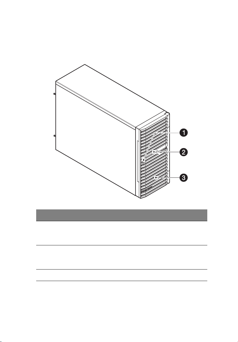
External and internal structure
Front bezel
9
No. Component
1 Security keylock
This lock secures the bezel door to protect the server unit from
unauthorized access.
2 LED indicator panel
For more information on the LED indicators description, go to
page 24.
3 Bezel door
Page 20
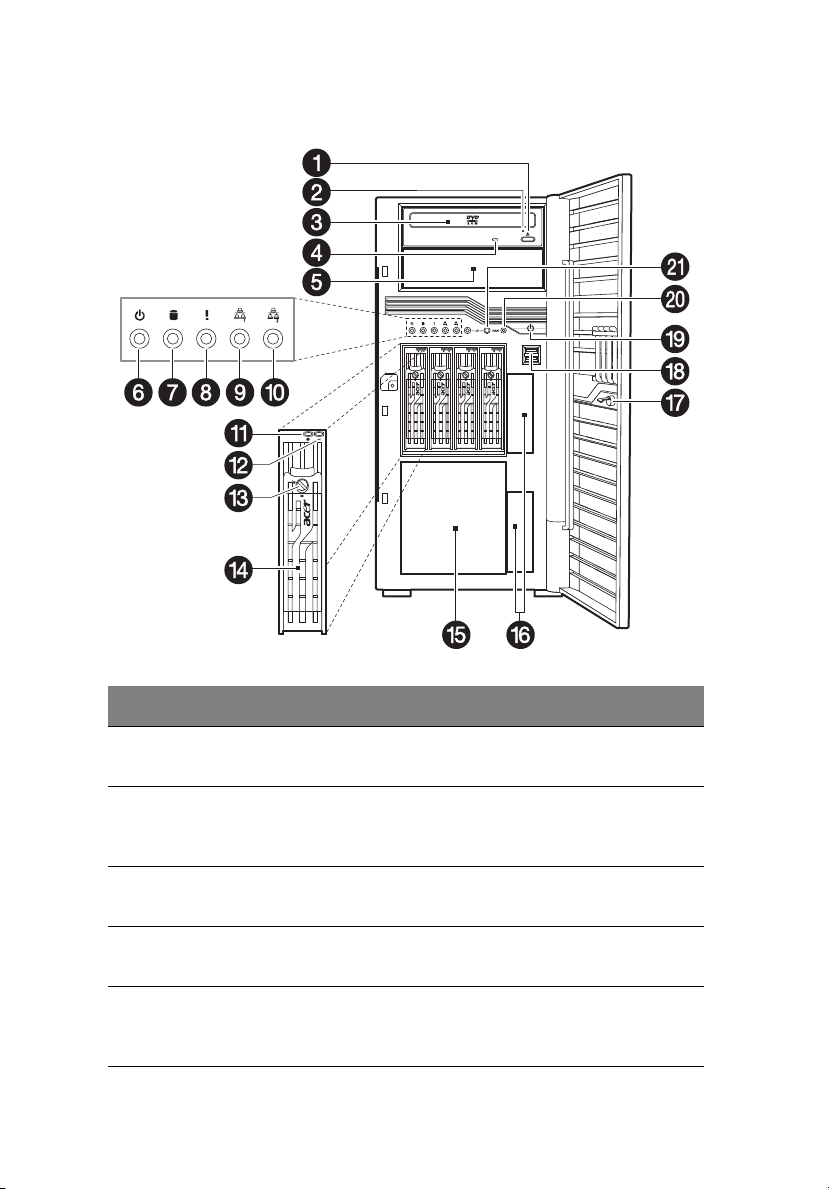
10
Front panel
1 System tour
No. Icon Component Description
1 DVD-ROM drive Eject
button
2 DVD-ROM drive
mechanical eject hole
3 DVD-ROM drive Disk drive for reading CD, VCD, and
4 DVD-ROM drive
activity indicator
5 5.25-inch drive bay Allows installation of additional
Press this button to open the DVD
drive tray.
When the DVD drive tray get
stucked, insert a paperclip to this
hole to manually eject the tray.
DVD contents.
When the LED indicator is lit, there
is an ongoing DVD drive activity.
storage devices. Go to page 4 for a
list of supported devices.
Page 21
No. Icon Component Description
6 Power indicator Indicates the system power status
(green).
11
7 HDD activity
indicator
8 Status/fault indicator Indicates the status of the system
9 LAN port 1 status
indicators
10 LAN port 2 status
indicators
11 Hot-plug HDD
activity indicator
12 Hot-plug HDD
status indicator
13 Hot-plug HDD
locking mechanism
14 HDD carrier Supports four hot-plug or
15 HDD cage bay Supports an optional HDD cage
Indicates the status of a system
hard drive (green/amber).
operations (green/amber).
Indicate the system network 1
connection status.
Indicate the system network 2
connection status.
Indicates the activity of a hot-plug
HDD installed in the system (green
/amber).
Indicates the status of the hot-plug
HDD installed in the system (green/
amber).
Locking mechanism to secure the
Hot-plug HDD.
easy-swap SAS or SATA2 HDDs.
(hot-plug or easy-swap).
16 HDD bay covers Covers for the HDD bays.
17 Lock Lock for preventing the system
from unauthorized access.
18 USB 2.0 ports Connects to USB devices.
19 Power button Press to turn the server on/off, or to
put it in standby mode.
Page 22

12
No. Icon Component Description
20 NMI switch If the system crashes or stops
normal operation, press the NMI
switch to mechanically force the
server to issue a non-maskable
interrupt. This will perform a
memory dump-writing the
contents of the server's CPU
registers and RAM to a network
server or to diskettes. This memory
dump can later be analyzed to
determine the cause of the
problem.
1 System tour
21 Unit identification
(UID) switch/indicator
Press the ID button to turn on the
ID LED indicator. This identifies a
particular unit within a server
group during servicing or
maintenance procedures.
Page 23
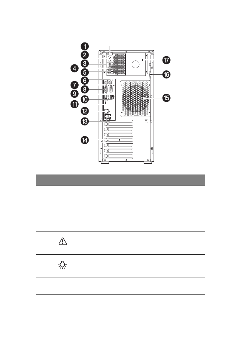
Rear panel
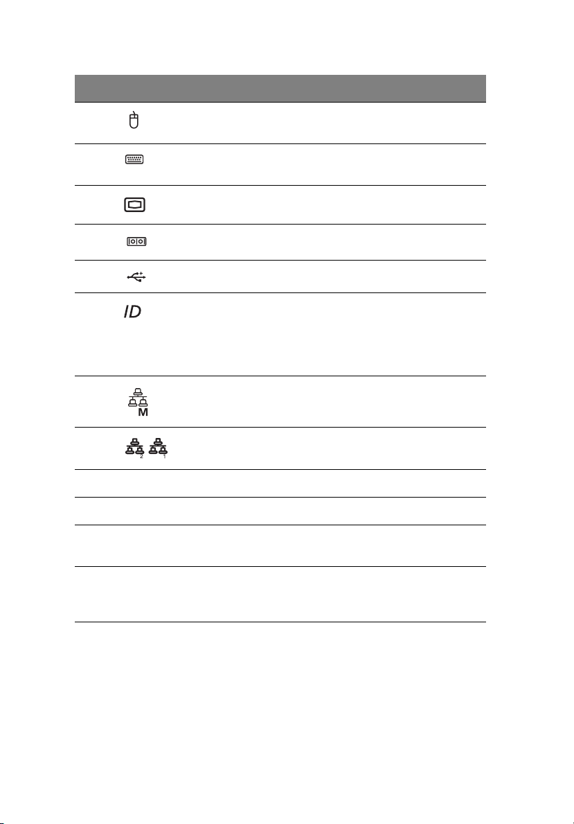
No. Icon Component Description
13
1 Power supply
module
release latch
2 Power supply
module cord
socket
3 Power supply
module fault
indicator
4 Power supply
module status
indicator
5Main power
supply module
Push down the latch to disengage the
module from the chassis.
Connect the system power cord here.
Indicates the occurrence of a fault
condition in the power supply
module. (green/amber)
Indicates the status of the power
supply module. (green)
Provides the system’s main power
supply.
Page 24
14
No. Icon Component Description
1 System tour
6 PS/2 mouse
port
7 PS/2 keyboard
port
8 Monitor port Connects to monitors.
9 Serial port Connects to serial devices.
10 USB 2.0 ports Connects to USB devices.
11 Unit
identification
(UID) switch/
indicator
12 Management
LAN port
13 Gigabit LAN
ports 1/2
14 PCI slot covers Protects the vacant expansion slots.
15 System fan Regulates the system airflow.
Connects to a PS/2 mouse.
Connects to a PS/2 keyboard.
Press to mark a particular server unit
within a server group (when
rack-mounted) for purpose of
identification during servicing or
maintenance procedures. (blue)
Fast Ethernet (RJ-45) port dedicated
for BMC management.
Connects to an Internet or intranet
network.
16 Lid switch Sent out warning alerts when the lid
is opened or compromised.
17 Redundant
power supply
module bay
Accommodates an optional hot-swap
redundant power supply module.
Page 25
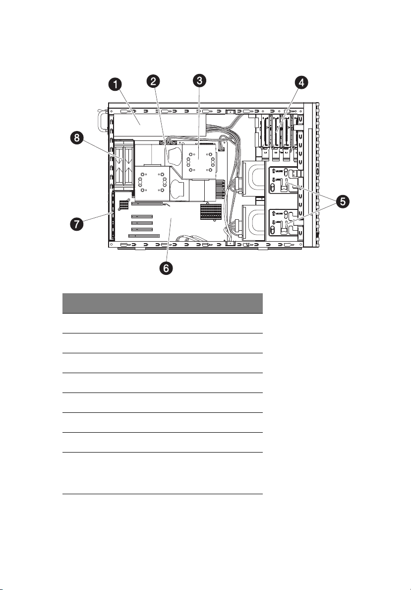
Internal components
No. Component
15
1 Redundant power supply module bay
2 Air duct
3 Heat sink fan (HSF) assemblies
4 Sliders for the 5.25-inch devices
5 Release sliders for the HDD cages
6 Mainboard
7PCI slot lock
8 System fan
Users have the option to purchase a
redundant system fan unit.
Page 26
16
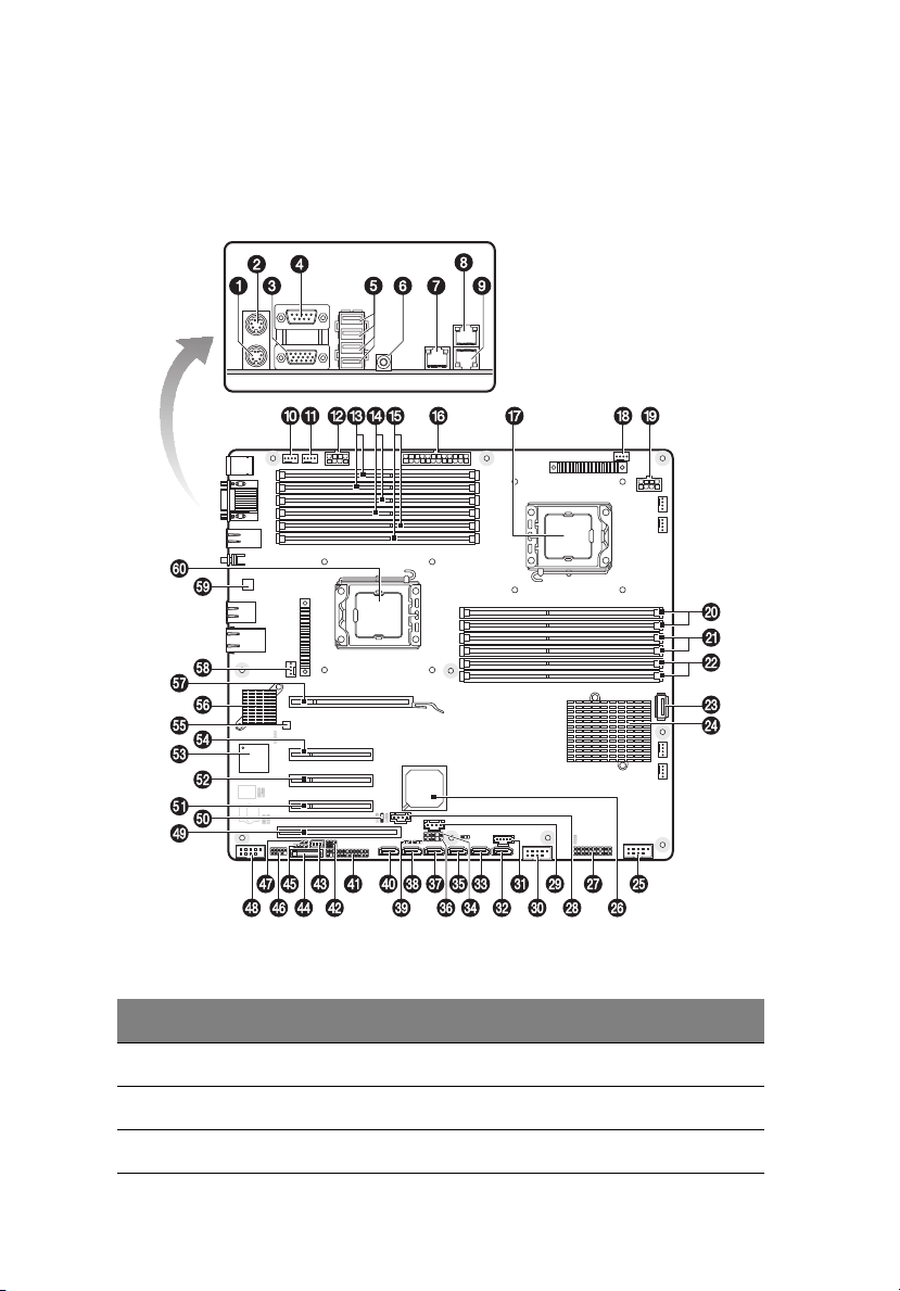
System boards
Mainboard
1 System tour
No. Code Description
1 KB PS/2 Keyboard port
2 MS PS/2 Mouse port
3 VGA VGA D-sub port
Page 27

No. Code Description
4 COM COM A serial port
5 USB USB ports
6 ID_SW ID switch
7 MNGT_NIC Management LAN port
8 GBE1 Gigabit LAN port 1
9 GBE2 Gigabit LAN port 2
10 FAN_SYS5 Redundant fan 1 connector (default)
11 FAN_SYS6 Redundant fan 2 connector
12 12V_AUX2 8-pin Power connector for Processor 2
17
13 DIMMF1/
DIMMF2
14 DIMME1/
DIMME2
15 DIMMD1/
DIMMD2
16 ATX 24-pin ATX Power connector
17 CPU1 Processor 1 Socket
18 FAN_CPU1 FAN connector for Processor 1
19 12V_AUX1 8-pin Power connector for Processor 1
20 DIMMA1/
DIMMA2
21 DIMMB1/
DIMMB2
22 DIMMC1/
DIMMC2
23 USB_A USB Type A connector
DDR3 memory slot 1/2 (Channel F) for
Processor 2
DDR3 memory slot 1/2 (Channel E) for
Processor 2
DDR3 memory slot 1/2 (Channel D) for
Processor 2
DDR3 memory slot 1/2 (Channel A) for
Processor 1
DDR3 memory slot 1/2 (Channel B) for
Processor 1
DDR3 memory slot 1/2 (Channel C) for
Processor 1
Page 28

18
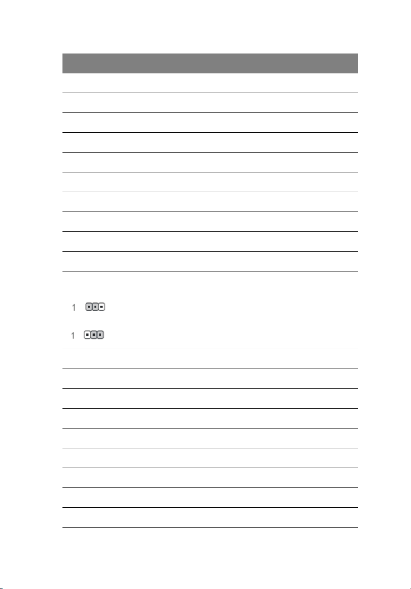
No. Code Description
24 U82 Intel® 5520 (North Bridge)
25 USB1 USB connector for internal USB (Tape
Device)
26 U60 Intel ICH 10R (South Bridge)
27 TPM TPM connector
28 J3 SMBus connector for backplane board 2
29 J2 SMBus connector for backplane board 1
30 USB_3 USB connector for SSD
31 PSMI1 PSMI connector
32 SATA0 SATA connector 0
33 SATA1 SATA connector 1
34 SGPIO_JP2 SGPIO connector for backplane board 2
35 SATA2 SATA connector 2
1 System tour
36 SGPIO_JP1 SGPIO connector for backplane board 1
37 SATA3 SATA connector 3
38 SATA4 SATA connector 4
39 CLR_CMOS Clear CMOS jumper
You may clear the CMOS data to its default values by this jumper.
Default value doesn’t include the “Shunter” to prevent from improper use of
this jumper. To clear CMOS, temporarily short 2-3 pin.
1-2 close: Normal operation (Default setting)
2-3 close: Clear CMOS
Page 29
No. Code Description
40 SATA5 SATA connector 5 for SATA ODD
41 F_PANEL Front panel connector
42 J1 BMC firmware upgrade connector
43 IPMB1 3-pin IPMB connector
44 BAT CMOS Battery
45 IPMB2 4-pin IPMB connector
46 USB2 USB connector for front USB ports
47 CASE_OPEN Chassis Intrusion connector
48 COMB COM B serial port connector
49 PCI5 PCI slot 5 (32bit/33MHz/3.3V)
50 BIOS_RVCR BIOS Recovery Jumper
1-2 close: Normal operation. (Default setting)
19
2-3 close: Enable BIOS Recovery function
51 PCI-E4 PCI-E x8 slot 4 (Gen1, x4 throughput)
52 PCI-E3 PCI-E x8 slot 3 (Gen2)
53 U5 BMC
54 PCI-E2 PCI-E x8 slot 2 (Gen2)
55 U188 Hardware monitor controller
56 U6 Gigabit Ethernet Network Controller
57 PCI-E1 PCI-E x16 slot 1 (Gen2)
58 FAN_CPU2 FAN connector for Processor 2
59 U24 10/100 Fast Ethernet PHY
Page 30

20
No. Code Description
60 CPU2 Processor 2 Socket
1 System tour
Page 31

Backplane board
The backplane board attached to rear of the hot-plug HDD cage is
what differentiate it from the easy-swap HDD cage model.
3.5” Backplane Board
21
No. Code Description
1 J14 Close 1-2: Two LED indication (default)
Close 2-3: Single LED indication (backward support)
2 J16 Backplane address setting:
3J15
4 J3 SMBUS connector for backplane cascade
5 J2 SMBUS connector to main board (J2)
Jumper Backplane 1 Backplane 2
J15 Close 2-3 Close 2-3
J16 Close 1-2 Close 2-3
Page 32

22
No. Code Description
6 J1 SMBUS connector to RAID card
7 SAS/CON SAS 8484 32-pin connector
8 J17 Close 1-2: default
Close 2-3: backward support
9 CN1/X1 Power connector (4-pin)
10 CN1/X2 Power connector (4-pin)
2.5” Backplane Board
1 System tour
No. Code Description
1 J27 Close 1-2: Two LED indication (default)
Close 2-3: Single LED indication (backward support)
2 J2 SMBUS connector to main board (J2)
Page 33

No. Code Description
3 J28 Backplane address setting:
4J29
5J30
6J31
7 CN2/X1 Power connector (4-pin)
8 J3 SMBUS connector for backplane cascade
9 CN1/X1 Power connector (4-pin)
10 J1 SMBUS connector to RAID card
11 SAS/CON1 SAS 8484 32-pin connector (port 0 ~ 3)
12 SAS/CON2 SAS 8484 32-pin connector (port 4 ~ 7)
Jumper Backplane 1 Backplane 2
J28 Close 2-3 Close 1-2
J29 Close 1-2 Close 2-3
J30 Close 2-3 Close 1-2
J31 Close 2-3 Close 1-2
23
Page 34

24
1 System tour
System LED indicators
This section discusses the different LED indicators located on the:
• Front panel
• Hot-plug HDD carrier
• LAN port
Knowing what each LED indicator signifies can aid in problem
diagnosis and troubleshooting.
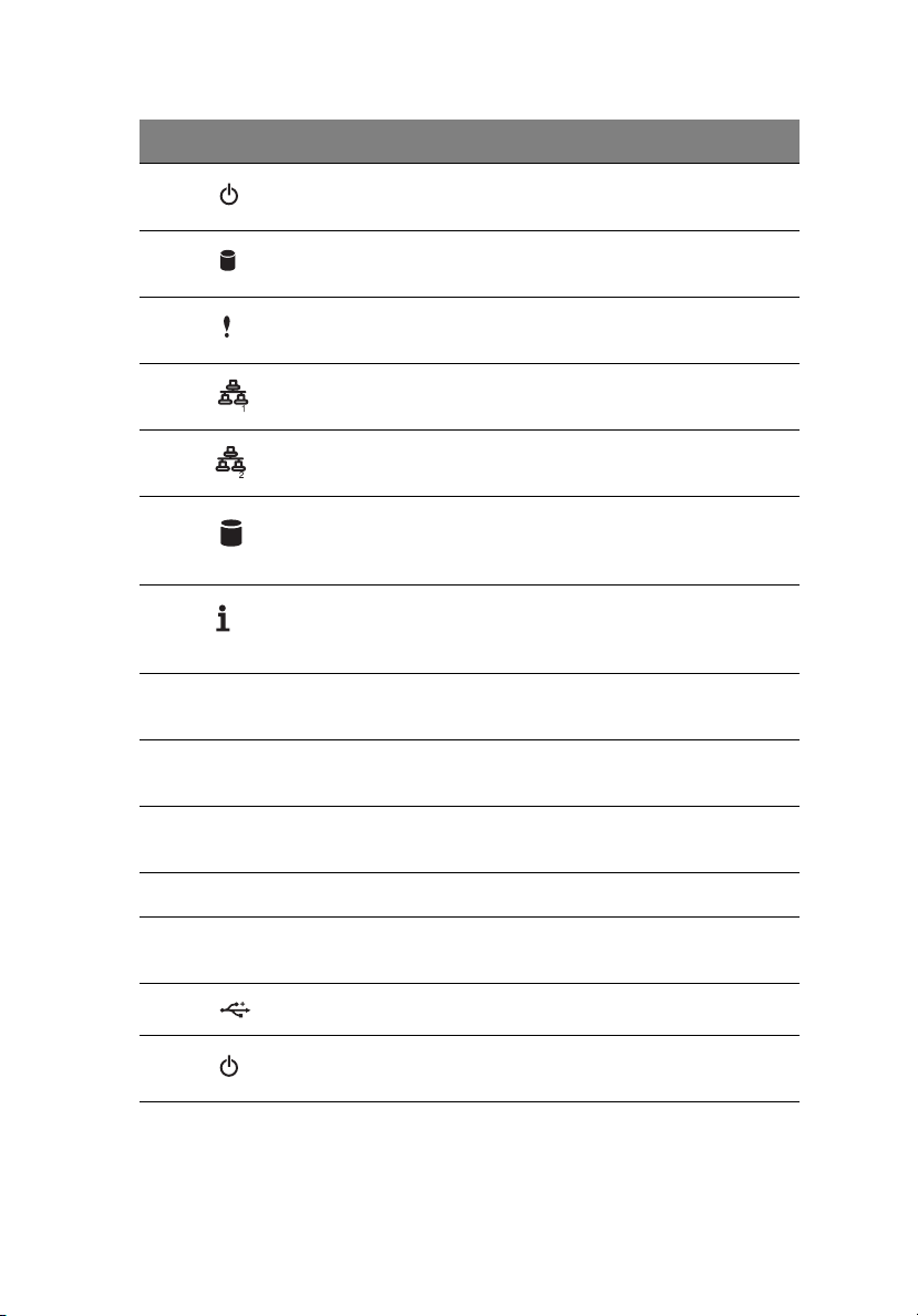
Front panel LED indicators
The six LED indicators mounted on the front bezel. These indicators
remain visible even when the bezel door is closed.
Indicator Color State Representative Status
Power Green ON S0: Power ON
Green Blink (1Hz with
at 50% duty
cycle)
N/A OFF S4
N/A OFF S5
HDD activity Green Blink HDD Access
N/A OFF No access and No HDD
S1: Sleep
fault
Page 35

System Status Green ON System Ready / No
Alarm
25
Green Blink (1Hz with
at 50% duty
cycle)
Amber ON Critical Alarm (Critical
Amber Blink (1Hz with
at 50% duty
cycle)
N/A OFF System not ready (Post
LAN Activity
(LAN1 and
LAN2)
System ID N/A OFF Normal
Green ON LAN Link / No Access
Green Blink LAN Access
N/A OFF Disconnect / Idle
Blue ON System Identification
System Ready but
degraded some CPU
fault, DIMM killed
power modules, Voltage
Power supply, critical
temperature and
voltage … etc. failure)
Non-critical Alarm (Noncritical temperature and
voltage)
error/NMI event/CPU or
terminator missing, …
etc.)
Page 36

26
1 System tour
Hot-plug HDD LED indicator
A drive activity LED indicator is mounted on the hot-plug HDD carrier.
The table below lists the possible drive states.
Status
HDD Present Steady ON OFF
HDD Access Blink OFF
HDD Failure OFF Steady ON
HDD Removed OFF Steady ON
HDD Insert and
rebuilding
HDD Locate Blink Blink
Steady ON Blink
Page 37

Gigabit LAN port LED indicators
27
LED
Indicator
Network
speed
(left)
Network
connection
(right)
LED #
1, 3, 5 Amber On 1000 Mbps link network
2, 4, 6 Green On Active network link
LED
Color
Green On 100 Mbps link network
Green Blinking Transmit/Receive activity
LED
State
Off 10 Mbps link network access
NIC State
access
access
Page 38

28
1 System tour
Page 39

2 System setup
Page 40

This chapter gives you instructions on how to
prepare the system for operation. Procedures for
connecting peripherals are also explained.
Page 41

Setting up the system
Pre-installation requirements
Selecting a site
Before unpacking and installing the system, select a suitable site for
the system for maximum efficiency. Consider the following factors
when choosing a site for the system:
• Near a grounded power outlet
• Clean and dust-free
• Stable surface free from vibration
• Well-ventilated and away from sources of heat
• Secluded from electromagnetic fields produced by electrical
devices such as air conditioners, radio and TV transmitters, etc.
Checking the package contents
Check the following items from the package:
• Acer Altos G540 M2 system
•Acer EasyBUILD
• Acer Altos G540 M2 accessory box
•System keys
TM
DVD Pack
31
If any of the above items are damaged or missing, contact your dealer
immediately.
Save the boxes and packing materials for future use.
Page 42

32
2 System setup
Connecting peripherals
The color-coded I/O port panel on the system rear accepts a variety of
compatible peripherals. Refer to the figure below for specific
connection instructions for each port.
Note: Consult the operating system manual for information on
how to configure the network setup.
Caution: Do not route the power cord where it will walked on or
pinched by items placed against it. The server is designed to be
electrically grounded (earthed). To ensure proper operation, plug
the power cord into a properly grounded AC outlet only.
Page 43

Turning on the system
After making sure that you have properly set up the system, applied
power, and connected all the necessary peripherals, you can now
power on the system. Follow the procedure below.
1 Unlock and open the bezel door.
33
Page 44

34
2 Press the power button.
The system starts up and displays a welcome message on the
monitor. After that, a series of power-on self-test (POST) messages
appears. The POST messages indicate if the system is running well
or not.
2 System setup
Note: If the system does not turn on or boot after pressing the
power button, go to the next section for the possible causes of the
boot failure.
Aside from the POST messages, you can determine if the system is in
good condition by checking if the following occurred.
• The power status indicator on the front panel lights up green.
• The Num Lock, Caps Lock, and Scroll Lock indicators on the
keyboard light up.
Power-on problems
If the system fails to boot after you have applied power, check the
following factors that might have caused the boot failure.
• The external power cord may be loosely connected.
Check the power cord connection from the power outlet to the
power cord socket on the rear panel. Make sure that the cord is
Page 45

properly connected to the power outlet and to the power cord
socket.
• No power comes from the grounded power outlet.
Have an electrician check your power outlet.
• Loose or improperly connected internal power cables.
Check the internal cable connections. If you are not confident to
perform this step, ask a qualified technician to assist you.
Warning! Make sure all power cords are disconnected from
the electrical outlet before performing this task.
Note: If you have gone through the preceding actions and the
system still fails to boot, ask your dealer or a qualified technician
for assistance.
35
Page 46

36
2 System setup
Configuring the system OS
The Altos G540 M2 comes with Acer EasyBUILD that allows users to
conveniently install the preferred operating system. To start using
EasyBUILD, follow the steps below.
1 Locate the EasyBUILD DVD included in the system package.
2 With the system turned on, press the DVD-ROM drive Eject button.
3 When the disc tray slides open, insert the EasyBUILD DVD with the
label side of the disc facing upward.
Note: When handling the disc, hold it by the edges to avoid
smudges or fingerprints.
4 Gently press the disc down to make sure that it is properly
inserted.
Caution: While pressing the disc, be careful not to bend the disc
tray. Make sure that the disc is properly inserted before closing
the disc tray. Improper insertion may damage both the disc and
the DVD-ROM drive.
5 Press the drive Eject button again to close the disc tray.
6 The Acer EasyBUILD sequence begins. Follow all onscreen
instructions.
For more information, refer to the EasyBUILD Installation guide.
Note: EasyBUILD only supports the Microsoft and Red Hat Linux
operating systems. The Windows or Red Hat installation disc(s) is
required to install the OS.
Page 47

Rack mount configuration
The Altos G540 M2 server is a dual-platform system that can be set up
in both tower and rack-mount configurations. A rack mount kit is
available for customers who prefer to mount the server in a system
rack. To purchase a rack mount kit, contact your local Acer
representative or order directly from http://www.acer.com/
The figure below shows the Altos G540 M2 server in a rack-mount
position.
.
37
For instructions on tower-to-rack configuration, refer to “Appendix B:
Rack mount configuration” on page 157.
Page 48

38
2 System setup
Turning off the system
There are two ways to turn off the server—via software or via
hardware. The software procedure below applies to a system running
on a Windows OS. For other NOS shutdown procedures, refer to the
related user documentation.
To turn off the system via software:
1 Press Ctrl+Alt+Delete on the attached keyboard or click the Start
on the Windows taskbar.
2Select Shut Down.
3Select Shut down from the drop-down menu, then click OK.
To turn off the system via hardware:
If you cannot shut down the server via software, press the power
button for at least four seconds. Quickly pressing the button may put
the server in a Suspend mode only.
Page 49

3 System upgrade
Page 50

This chapter discusses the precautionary
measures and installation procedures you
need to know when upgrading the system.
Page 51

Installation precautions
Before you install any server component, it is recommended that you
read the following sections first. These sections contain important ESD
precautions along with pre-installation and post-installation
procedures.
ESD precautions
Electrostatic discharge (ESD) can damage static-sensitive hardware
components, such as the processor, disk drives, and the system boards.
Always observe the following precautions before you install a server
component:
• Do not remove a component from its protective packaging until
you are ready to install it.
• Do not touch the component pins, leads, or circuitry.
• Components with a Printed Circuit Board (PCB) assembly should
always be laid with the assembly-side down.
• Wear a wrist grounding strap and attach it to a metal part of the
server before handling components. If a wrist strap is not
available, maintain contact with the server throughout any
procedure requiring ESD protection.
• Keep the work area free of nonconductive materials, such as
ordinary plastic assembly aids and foam packing.
41
Page 52

42
3 System upgrade
Pre-installation instructions
Perform the steps below before you open the server or before your
remove or replace any component.
Warning! Failure to properly turn off the server before you
start perform any hardware configuration may cause
serious damage and bodily harm. Do not attempt the
procedures described in the following sections unless you
are a qualified service technician.
1 Turn off the server and all connected peripherals.
2 Unplug all power cables from their outlets.
3 Disconnect all telecommunication cables from their ports.
4 Place the server on a flat, stable surface.
5 Open the server according to the instructions on page 43.
6 Follow the ESD precautions described in the previous section when
handling a server component.
Post-installation instructions
Perform the steps below after installing a server component.
1 See to it that all components are installed according to the
described step-by-step instructions.
2 Reinstall any expansion board(s), peripheral(s), bracket (s) and
system cable(s) that have previously been removed.
3 Reinstall the side panel.
4 Reconnect the power, peripheral, and telecommunication cables.
5 Turn on the system.
Page 53

43
Opening the server
Caution: Before you proceed, make sure that you have turned off
the system and all peripherals connected to it. Read the
“Pre-installation instructions” section on page 42.
You need to open the server before you can install upgrade
components. The front bezel and (left) side panel are removable to
allow access to the server’s internal components. Refer to the
following sections for instructions.
Removing the side panel
1 Perform the pre-installation instructions described on page 41.
2 Unlock the security keylock.
3 Remove the two thumb screws on the back panel.
4 Slide the side panel toward the rear of the chassis to disengage it.
Page 54

44
3 System upgrade
Removing the front bezel
1 Remove the side panel.
Refer to the previous section for instructions.
2 Remove the front bezel.
(1) Release the bezel door retention tabs from the chassis interior.
(2) Firmly bump the bezel as shown to loosen it.
(3) Pull the bezel away from the chassis.
Page 55

45
Configuring the hard drive
The two HDD cage bays of the Altos G540 M2 accommodates both
hot-plug and easy-swap HDD cage models. The main difference
between these two cage models is the presence of a backplane board
on the rear side of the hot-plug HDD cage. Both cage models support
up to four SATA2 or SAS hard disk drives.
The system ships out with only a single HDD cage occupying the top
cage bay. You have the option to purchase an extra HDD cage to
provide the system with additional storage capacity and scalability.
Contact your local Acer representative for more information.
The system supports 3.5” or 2.5” HDDs. It cannot support both at once.
If the systems ships with the 3.5” HDDs, then any additional HDDs
should also be the same size. That goes the same for the 2.5” HDDs.
Caution: You cannot mix 3.5” HDDs with 2.5” HDDs on the same
system.
Note: The HDD cage comes with HDD dummy covers. You need
to purchase a blank HDD carrier to install a hard drive.
Installing a 3.5“HDD cage
1 Perform the pre-installation instructions described on page 41.
Page 56

46
3 System upgrade
2 Remove the plastic cover by releasing it from the latches.
3 Remove the HDD cage bay metal cover from the front chassis.
(1) Remove the screws securing the cover.
(2) Detach the cover from chassis.
Store this cover for future reinstallation.
Page 57

4 Install the HDD cage.
(1) Slide the cage into the lower bay with the HDD carriers facing
front.
Then lock the cage by sliding the locker down as shown.
47
If you have installed a hot-plug HDD cage, proceed to next
step for related drive cable connections.
Drive cable connections for an easy-swap HDD can be found
on page page 58.
(2) Connect the following cables to the hot-plug HDD cage
backplane board.
(1) Connect the hard drive power cables to the CN1 and CN2
connectors of the backplane board.
Page 58

48
(2) Connect the SAS/SATA2 cable to the SAS/CON connector
of the backplane board.
5 Observe the post-installation instructions described on page 42.
For instructions on how to install a hard drive in an easy-swap HDD
cage, go to page 57.
For instructions on how to install a hard drive in a hot-plug HDD
cage, go to page 55.
3 System upgrade
Removing a HDD cage
1 Perform the pre-installation instructions described on page 41.
2 Prepare the HDD cage for removal.
• For a hot-plug HDD cage, disconnect the data and power
cables from the backplane board, then remove all HDDs from
the cage.
• For an easy-swap HDD cage, disconnect the data and power
cables from their HDD connectors, then remove all HDDs from
the cage.
3 Remove the HDD cage.
(1) Move the release slider all the way up to unlock the hot-plug
HDD cage.
Page 59

(2) Remove the cage from the HDD bay.
4 Observe the post-installation instructions described on page 42.
49
Page 60

50
3 System upgrade
Installing a 2.5“HDD cage
1 Perform the pre-installation instructions described on page 41.
2 Remove the 2 plastic covers by releasing it from the latches.
Page 61

3 Place the top plastic cover as shown.
4 Remove the HDD cage bay metal cover from the front chassis.
(1) Remove the screws securing the cover.
(2) Detach the cover from chassis.
Store this cover for future reinstallation.
51
5 Install the HDD cage.
Page 62

52
3 System upgrade
(1) Slide the cage into the lower bay with the HDD carriers facing
front.
Then lock the cage by sliding the locker down as shown.
If you have installed a hot-plug HDD cage, proceed to next
step for related drive cable connections.
Drive cable connections for an easy-swap HDD can be found
on page page 58.
(2) Connect the following cables to the hot-plug HDD cage
backplane board.
(1) Connect the hard drive power cables to the CN1 and CN2
connectors of the backplane board.
Page 63

(2) Connect the SAS/SATA2 cable to the SAS/CON connector
of the backplane board.
6 Observe the post-installation instructions described on page 42.
For instructions on how to install a hard drive in an easy-swap HDD
cage, go to page 57.
For instructions on how to install a hard drive in a hot-plug HDD
cage, go to page 55.
53
Removing a HDD cage
1 Perform the pre-installation instructions described on page 41.
2 Prepare the HDD cage for removal.
• For a hot-plug HDD cage, disconnect the data and power
cables from the backplane board, then remove all HDDs from
the cage.
• For an easy-swap HDD cage, disconnect the data and power
cables from their HDD connectors, then remove all HDDs from
the cage.
3 Remove the HDD cage.
(1) Move the release slider all the way up to unlock the hot-plug
HDD cage.
Page 64

54
3 System upgrade
(2) Remove the cage from the HDD bay.
4 Observe the post-installation instructions described on page 42.
Page 65

Installing an additional hard drive
The Altos G540 M2 HDD cage models supports both SATA2 and SAS
hard drives in different capacities.
Note: You cannot mix the 3.5” HDD with the 2.5” HDD on the
system.
To install 3.5” a hot-plug hard drive:
1 If necessary, unlock the front bezel, then pull it open.
2 Remove the HDD dummy cover from the cage.
55
3 Prepare the blank HDD carrier for installation.
(1) Remove the four screws that secures the blank frame.
You will use these screws to secure the hard disk later.
Page 66

56
3 System upgrade
(2) Detach the plastic frame from the HDD carrier.
4 Align the new hard disk with the HDD carrier, then secure it with
the four screws you removed in step 3-1.
5 Install the new hard drive into the cage.
Page 67

(1) Slide the drive into the cage with the carrier handle still
extended.
(2) Make sure that the drive is properly inserted before pushing
the handle back until it clicks into place.
6 Set up the new hard drive’s RAID configuration.
For related instructions, go to the “RAID configuration utilities”
section on page 150.
57
To install 2.5” a hot-plug hard drive:
1 If necessary, unlock the front bezel, then pull it open.
Page 68

58
2 Remove the HDD dummy cover from the cage.
3 Prepare the blank HDD carrier for installation.
(1) Remove the four screws that secures the blank frame.
You will use these screws to secure the hard disk later.
3 System upgrade
Page 69

(2) Detach the plastic frame from the HDD carrier.
59
Page 70

60
3 System upgrade
4 Align the new hard disk with the HDD carrier, then secure it with
the four screws you removed in step 3-1.
5 Install the new hard drive into the cage.
(1) Slide the drive into the cage with the carrier handle still
extended.
Page 71

(2) Make sure that the drive is properly inserted before pushing
the handle back until it clicks into place.
6 Set up the new hard drive’s RAID configuration.
For related instructions, go to the “RAID configuration utilities”
section on page 150.
61
Page 72

62
3 System upgrade
Configuring a 5-25 inch storage device
The three 5.25-inch device bays support a variety of storage devices for
additional storage capacity and scalability. Go to page 4 for a list of
supported storage devices.
By default, the system ships with a DVD-ROM drive installed on the
topmost device bay. You can choose to replace these default drives, or
you can install a new storage device on the second device bay.
To install an optional storage device:
1 Perform the pre-installation instructions described on page 41.
2 Remove the two screws that secure the cover of the empty
5.25-inch drive bay (1), then detach the cover (2).
Keep this cover for future reinstallation.
3 Install the new 5.25-inch storage device.
The instructions given below apply to a regular 5.25-inch storage
device.
Page 73

Note: There is an extra bracing lock on the side of the 5.25-in
drive cage for installing another 5.25-inch device.
4 Install the bracing lock tab as shown.
63
(1) Slowly slide the drive into the drive bay.
Page 74

64
(2) Connect the power and SATA cables to the new 5.25-inch
drive.
5 Observe the post-installation instructions described on page 42.
3 System upgrade
To remove a defective storage device:
1 Perform the pre-installation instructions described on page 41.
Page 75

2 Remove the cables as shown (1 and 2). Press on both side of the
bracing lock tab (3) and pull out the drive from the drive bay (4).
3 Remove the bracing lock tab from the old DVD drive.
65
Page 76

66
3 System upgrade
4 Install the bracing lock tab on the new DVD device as shown.
(1) Slowly slide the drive into the drive bay.
Page 77

(2) Connect the power and SATA cables to the new 5.25-inch
drive.
67
Page 78

68
3 System upgrade
Upgrading the processor
This section explains the procedures for removing and installing the
processor and heat sink fan (HSF) assembly.
Processor configuration guidelines
The mainboard supports up to two Intel® Xeon™ processor 5500
series. You have the option to upgrade the default processor or install
a second one for a dual-processor configuration.
Observe the following guidelines when replacing or installing a
processor.
• The CPU 1 socket must always be populated. If no processor is
installed in this socket, the system will fail to boot.
• Before removing a processor, make sure to back up all important
system files.
• When installing a second processor, make sure it has same
stepping and frequency specifications as the default processor.
• Handle the processor and the HSF assembly carefully. Damage to
either may prevent the system from functioning properly.
Note: A long-nosed screwdriver is needed to remove/install the
HSF assembly
.
To upgrade the default processor:
1 Perform the pre-installation instructions described on page 41.
2 Lay the server on its side (components showing).
Page 79

3 Remove the screws securing the HSF air duct assembly. Carefully
remove the HSF air duct assembly. Remember to keep the screws in
a safe place for later reassembly.
69
4 Disconnect the processor 1 HSF cable from its mainboard
connector and remove the HSF assembly.
(1) Use a long-nosed screwdriver to loosen the four HSF
mounting pins.
Page 80

70
3 System upgrade
(2) Once you have loosened all four mounting pins, lift the HSF
away from the mainboard.
(3) Lay down the HSF in an upright position—with the thermal
patch facing upward. Do not let the thermal patch touch the
work surface.
Use an alcohol pad to wipe off the thermal grease from both the
HSF assembly and the processor socket retention plate.
5 Remove the default processor.
Warning! The processor becomes very hot when the system
is on. Allow it to cool off first before handling.
(1) Release then lift up the load lever.
(2) Open the retention plate to expose the socket body.
Page 81

(3) Grasp the processor by its edges and lift it out of its socket.
6 Store the old processor inside an anti-static bag.
7 Remove the new processor from its protective packaging.
8 Install the new processor.
(1) Hold the processor by its edges, then insert it in the socket.
Make sure that the alignment tabs on the socket fit the two
notch located on the edge of the processor. The pins are
keyed in such a way that you cannot install the processor in
the wrong orientation without bending the pins.
(2) Close the retention plate.
71
Page 82

72
3 System upgrade
(3) Engage the load lever back into place.
9 Apply the thermal interface material.
(1) Use an alcohol pad to wipe off the old thermal grease from
both the HSF assembly and the processor socket retention
plate.
(2) Apply a thin layer of an Acer-approved thermal interface
material before installing the HSF.
Make sure that only a very thin layer is applied so that both
contact surfaces are still visible.
10 Reinstall the HSF assembly.
(1) Align then insert the HSF on top of the retention plate.
Page 83

(2) Use a long-nosed screwdriver to tighten the four HSF
mounting pins to secure the assembly. Reconnect the HSF
cable to its mainboard connector.
Refer to the “Mainboard” section on page 16 for the location of
73
Page 84

74
the HSF connectors.
11 Replace the HSF air duct assembly. Make sure to seat the HSF air
duct assembly properly before replacing the screws in place.
3 System upgrade
12 Observe the post-installation instructions described on page 42.
To install a second processor:
1 Perform steps 1 through 4 of the previous section.
2 Prepare the processor socket 2 for installation.
Refer to steps 5-1 and 5-2 of the previous section.
3 Install the new processor.
Refer to steps 7 and 8 of the previous section.
4 Reinstall the HSF assembly.
(1) Align then insert the HSF on top of the retention plate.
Page 85

(2) Use a long-nosed screwdriver to tighten the four HSF
mounting pins to secure the assembly.
5 Observe the post-installation instructions described on page 42.
75
Page 86

76
3 System upgrade
Upgrading the system memory
This section explains the procedures for removing and installing a
fully-buffered memory module.
Memory Configuration Guideline
Altos G540 M2 has twelve DIMM slots. Each CPU controls six DIMM
slots. The DIMM slots support three channel DDR3-1333 registered/
unbuffered ECC memory modules. For CPU1, it will be channel A, B &C.
For CPU2, it will be channel D,E &F. Each channel has 2 sockets. The
farthest socket to CPU is socket 1 (A1,B1,C1,D1,E1,F1 in color BLUE ),
while the nearest one is socket 2 (A2,B2,C2,D2,E2,F2 in color black). For
all memory modes, the socket 1 in each channel should be populated
first. If socket 1 is empty, socket 2 can't be used.
Note:
(1) When you are using a single-processor server, you should
install the memory module into DIMM A1 to DIMM C2
slots.
Page 87

77
(2) The DIMM D1 to DIMM F2 slots are enabled when a
second CPU is installed on the mainboard.
For the system to function, DIMM modules must be installed following
the slot sequence listed below. DIMM module of the same type, size
and manufacturer must be installed in the same colored DIMM slots.
• CPU 1 - Populate DIMM slots A1 first, followed by slots B1, C1, A2,
B2, and C2.
• CPU 2 - Populate DIMM slots D1 first, followed by slots E1, F1, D2,
E2, and F2.
• To ensure data integrity, use only Acer-approved 240-pin, DDR3
Registered/Unbufferred DIMM ECC modules in 1 GB, 2 GB, 4 GB, or
8 GB capacities.
• Use identical modules—same specification for size, speed, and
organization.
Independent Mode:
Singel processor configuration
Observe the population sequence illustrated in the table below when
installing a memory module.
Tot a l
Capacity
1GB 1GB
2GB 1GB 1GB
3GB 1GB 1GB 1GB
4GB 1GB 1GB 1GB 1GB
6GB 1GB 1GB 1GB 1GB 1GB 1GB
2GB 2GB
4GB 2GB 2GB
6GB 2GB 2GB 2GB
8GB 2GB 2GB 2GB 2GB
12GB 2GB 2GB 2GB 2GB 2GB 2GB
DIMM A2 DIMM A1 DIMM B2 DIMM B1 DIMM C2 DIMM C1
Page 88

78
3 System upgrade
To ta l
Capacity
4GB 4GB
8GB 4GB 4GB
12GB 4GB 4GB 4GB
16GB 4GB 4GB 4GB 4GB
24GB 4GB 4GB 4GB 4GB 4GB 4GB
8GB* 8GB
16GB* 8GB 8GB
24GB* 8GB 8GB 8GB
32GB* 8GB 8GB 8GB 8GB
48GB* 8GB 8GB 8GB 8GB 8GB 8GB
DIMM A2 DIMM A1 DIMM B2 DIMM B1 DIMM C2 DIMM C1
Note: *Support depends on 8GB DIMM available
Dual processor configuration
Observe the population sequence illustrated in the table below when
installing a memory module.
To ta l
Capacity
2GB 1 GB 1 GB
3GB 1 GB 1 GB 1 GB
4GB 1 GB 1 GB 1 GB 1 GB
6GB 1 GB 1 GB 1 GB 1 GB 1 GB 1 GB
8GB 1 GB 1 GB 1 GB 1 GB 1 GB 1 GB 1 GB 1 GB
9GB 1 GB 1 GB 1 GB 1 GB 1 GB 1 GB 1 GB 1 GB 1 GB
12GB 1 GB 1 GB 1 GB 1 GB 1 GB 1 GB 1 GB 1 GB 1 GB 1 GB 1 GB 1 GB
4GB 2 GB 2GB
6GB 2 GB 2 GB 2 GB
8GB 2 GB 2 GB 2 GB 2 GB
12GB 2 GB 2 GB 2 GB 2 GB 2 GB 2 GB
16GB 2 GB 2 GB 2 GB 2 GB 2 GB 2 GB 2 GB 2 GB
A1 A2 B1 B2 C1 C2 D1 D2 E1 E2 F1 F2
DIMM
Page 89

79
Tot a l
Capacity
18GB 2 GB 2 GB 2 GB 2 GB 2 GB 2 GB 2 GB 2 GB 2 GB
24GB 2 GB 2 GB 2 GB 2 GB 2 GB 2 GB 2 GB 2 GB 2 GB 2 GB 2 GB 2 GB
8GB 4 GB 4 GB
12GB 4 GB 4 GB 4 GB
16GB 4 GB 4 GB 4 GB 4 GB
24GB 4 GB 4 GB 4 GB 4 GB 4 GB 4 GB
32GB 4 GB 4 GB 4 GB 4 GB 4 GB 4 GB 4 GB 4 GB
36GB 4 GB 4 GB 4 GB 4 GB 4 GB 4 GB 4 GB 4 GB 4 GB
48GB 4 GB 4 GB 4 GB 4 GB 4 GB 4 GB 4 GB 4 GB 4 GB 4 GB 4 GB 4 GB
16GB* 8 GB 8 GB
24GB* 8 GB 8 GB 8 GB
32GB* 8 GB 8 GB 8 GB 8 GB
48GB* 8 GB 8 GB 8 GB 8 GB 8 GB 8 GB
64GB* 8 GB 8 GB 8 GB 8 GB 8 GB 8 GB 8 GB 8 GB
72GB* 8 GB 8 GB 8 GB 8 GB 8 GB 8 GB 8 GB 8 GB
96GB* 8 GB 8 GB 8 GB 8 GB 8 GB 8 GB 8 GB 8 GB 8 GB 8 GB 8 GB 8 GB
A1 A2 B1 B2 C1 C2 D1 D2 E1 E2 F1 F2
DIMM
Note: *Support depends on 8GB DIMM available
Mirroring or Lockstep mode :
• Mirroring mode & Lockstep mode need the channel A & channel B
with identical DIMMs. A1 and B1 should be the same type, size and
manufacturer. A2 and B2 memory should be the same type, size
and manufacturer.
• Channel C has no function in this mode.
• Same rule is applied to the CPU2 memory channel D,E,F.
• For mirroring mode, the memory contain a primary image and a
copy of the primary image. Therefore, the effective size of
memory is reduced by at least one-half.
Page 90

80
Single Processor Configuration
3 System upgrade
Tot al
Capacity
2GB 1GB 1GB
4GB 1GB 1GB 1GB 1GB
4GB 2GB 2GB
8GB 2GB 2GB 2GB 2GB
8GB 4GB 4GB
16GB 4GB 4GB 4GB 4GB
16GB* 8GB 8GB
32GB* 8GB 8GB 8GB 8GB
DIMM A2DIMM A1DIMM B2DIMM B1DIMM C2DIMM
Note: *Support depends on 8GB DIMM available
C1
Page 91

Dual Processor Configuration
81
Tot a l
Capacity
2GB 1GB 1GB
4GB 1GB 1GB 1GB 1GB
6GB 1GB 1GB 1GB 1GB 1GB 1GB
8GB 1GB 1GB 1GB 1GB 1GB 1GB 1GB 1GB
4GB 2GB 2GB
8GB 2GB 2GB 2GB 2GB
12GB 2GB 2GB 2GB 2GB 2GB 2GB
16GB 2GB 2GB 2GB 2GB 2GB 2GB 2GB 2GB
8GB 4GB 4GB
16GB 4GB 4GB 4GB 4GB
24GB 4GB 4GB 4GB 4GB 4GB 4GB
32GB 4GB 4GB 4GB 4GB 4GB 4GB 4GB 4GB
16GB* 8GB 8GB
32GB* 8GB 8GB 8GB 8GB
48GB* 8GB 8GB 8GB 8GB 8GB 8GB
64GB* 8GB 8GB 8GB 8GB 8GB 8GB 8GB 8GB
A2 A1 B2 B1 C2 C1 D2 D1 E2 E1 F2 F1
DIMM
Note: *Support depends on 8GB DIMM available
To remove a DDR3 Registered/Unbufferred DIMM:
Important: Before removing a DDR3 Registered/Unbufferred
DIMM, make sure to back up all important system files. Also, note
that DDR3 Registered/Unbufferred DIMMs should be removed in
pairs.
Page 92

82
3 System upgrade
1 Perform the pre-installation instructions described on page 41.
2 Lay the server on its side (components showing).
3 Remove the HSF air duct assembly to access to the DDR3
Registered/Unbufferred DIMM slots.
4 Remove the DDR3 Registered/Unbufferred DIMM.
(1) Press the holding clips on both sides of the socket outward to
release the DIMM.
Page 93

83
(2) Gently pull the DIMM upward to remove it from the socket.
5 If you intend to install a new DDR3 Registered/Unbufferred DIMM,
proceed to the next section for related procedure, otherwise
reinstall the air duct, then observe the post-installation
instructions described on page 42.
To install an DDR3 Registered/Unbufferred DIMM:
1 Perform steps 1 through 3 of the previous section.
2 Select an empty DDR3 Registered/Unbufferred DIMM slot.
3 If necessary, open the holding clips of the selected DDR3
Registered/Unbufferred DIMM slot.
4 Remove the new DDR3 Registered/Unbufferred DIMM from its
protective packaging, handling it by the edges.
5 Install the DDR3 Registered/Unbufferred DIMM.
(1) Align the DDR3 Registered/Unbufferred DIMM so that the
notch on the slot fits the keyed edge of the module, then
press the module at both ends to seat it fully into the slot.
If you insert an DDR3 Registered/Unbufferred DIMM but it
does not fit easily into the slot, you have inserted it incorrectly.
Reverse the orientation of the module and insert it again.
Page 94

84
(2) Firmly press the holding clips inward to lock the DDR3
Registered/Unbufferred DIMM in place.
If the holding clips do not close, the DDR3 Registered/
Unbufferred DIMM is not properly inserted.
6 Reinstall the air duct.
3 System upgrade
Page 95

7 Observe the post-installation instructions described on page 42.
The system automatically detects the amount of memory installed.
Run the BIOS setup to view the new value for total system memory
and make a note of it.
85
Page 96

86
3 System upgrade
Installing an expansion card
This section explains how to install an expansion card.
I/O interface
Altos G540 M2 has five PCI Express® and PCI expansion slots, namely:
• One PCI Express® 2.0 x16 slot
• Two PCI Express® 2.0 x8 slots (with eight PCI Express® 2.0 lanes)
• One PCI Express® x8 slot (with four PCI Express® lanes)
• One PCI (32-bit / 3.3 V) slot
To install an expansion card:
1 Perform the pre-installation instructions described on page 41.
2 If necessary, remove any cables that prevent access to the
processor sockets.
3 Locate an empty expansion slot that is compatible with the
specification of the card you intend to install.
4 Install the expansion card.
Page 97

(1) Remove the screw securing the slot cover of the selected
expansion slot. Set aside the screw as it will be used to secure
the expansion card later on.
(2) Pull out the slot cover and store it for reassembly later.
87
Caution: Do not discard the slot cover. If the expansion card is
removed in the future, the slot cover must be reinstalled to
maintain proper system cooling.
Remove the expansion card from its protective packaging,
handling it by the edges.
Page 98

88
(3) Insert the card into the selected slot.
Make sure that the card is properly seated.
Replace the screw to secure the card in place.
3 System upgrade
(4) Connect the necessary cables to the expansion card as
required.
5 Observe the post-installation instructions described on page 42.
When you turn on the system, the BIOS setup automatically
detects and assigns resources to the new device (applicable only to
Plug-and-Play expansion cards).
Page 99

89
Installing the TPM module
The optional TPM module allows system administrators to enhance the
security of Altos G540 M2 system.
To install the TPM module:
1 Perform the pre-installation instructions described on page 30.
2 Locate the TPM module connector. If necessary, remove any boards
or cables that prevent access to it.
3 Remove the TPM module from its protective packaging, handling
it by the edges.
4 Install the TPM module.
(1) Insert the TPM module into the TPM module connector.
5 Observe the post-installation instructions described on page 42.
Page 100

90
3 System upgrade
Installing the System Fan module
The optional System Fan module enhances the stability of Altos G540
M2 system by cooling it in a humid area.
To install the System Fan module:
1 Perform the pre-installation instructions described on page 30.
2 Remove the new System Fan module from its protective
packaging.
3 Install the new System Fan module by sliding it into an empty slot
as shown.
4 Observe the post-installation instructions described on page 42.
Removing a defective System Fan module:
1 Perform the pre-installation instructions described on page 30.
 Loading...