

Acer ALTOS G500 User Manual

Acer Altos G500
User’s guide

Copyright © 2001 Acer Incorporated
All Rights Reserved.
Acer Altos G500
User’s guide
Changes may be made periodically to the information in this publication without obligation
to notify any person of such revision or changes. Such changes will be incorporated in new
editions of this manual or supplementary documents and publications. This company makes
no representations or warranties, either expressed or implied, with respect to the contents
hereof and specifically disclaims the implied warranties of merchantability or fitness for a
particular purpose.
Record the model number, serial number, purchase date, and place of purchase information in
the space provided below. The serial number and model number are recorded on the label
affixed to your computer. All correspondense concerning your unit should include the serial
number, model number, and purchase information.
No part of this publication may be reproduced, stored in a retrieval system, or transmitted, in
any form or by any means, electronic, mechanical, photocopy, recording, or otherwise,
without the prior written permission of Acer Incorporated.
Model Number : _________________________________
Serial Number: ___________________________________
Purchase Date: ___________________________________
Place of Purchase: ________________________________
Acer and the Acer Logo are registered trademarks of Acer Inc. Other company’s product
names or trademarks are used herein for identification purposes only and belong to their
respective companies.

iii
Notices
FCC notice
This device has been tested and found to comply with the limits for a Class B
digital device pursuant to Part 15 of the FCC Rules. These limits are designed to
provide reasonable protection against harmful interference in a residential
installation. This device generates, uses, and can radiate radio frequency
energy, and if not installed and used in accordance with the instructions, may
cause harmful interference to radio communications.
However, there is no guarantee that interference will not occur in a particular
installation. If this device does cause harmful interference to radio or television
reception, which can be determined by turning the device off and on, the user
is encouraged to try to correct the interference by one or more of the following
measures:
• Reorient or relocate the receiving antenna
• Increase the separation between the device and receiver
• Connect the device into an outlet on a circuit different from that to which
the receiver is connected
• Consult the dealer or an experienced radio/television technician for help
Notice: Shield cables
All connections to other computing devices must be made using shielded cables
to maintain compliance with FCC regulations.
Notice: Peripheral devices
Only peripherals (input/output devices, terminals, printers, etc.) certified to
comply with the Class B limits may be attached to this equipment. Operation
with noncertified peripherals is likely to result in interference to radio and TV
reception.
Caution! Changes or modifications not expressly approved by the
manufacturer could void the user’s authority, which is granted by
the Federal Communications Commission, to operate this
computer.

iv
Use conditions
This part complies with Part 15 of the FCC Rules. Operation is subject to the
following two conditions: (1) this device may not cause harmful interference,
and (2) this device must accept any interference received, including interference
that may cause undesired operation.
Notice: Canadian users
This Class B digital apparatus meets all requirements of the Canadian
Interference-Causing Equipment Regulations.
Remarque à l’intention des utilisateurs canadiens
Cet appareil numérique de la classe B respected toutes les exigences du
Règlement sur le matériel brouilleur du Canada
.
Important safety instructions
Read these instructions carefully. Save these instructions for future
reference.
1 Follow all warnings and instructions marked on the product.
2 Unplug this product from the wall outlet before cleaning. Do not
use liquid cleaners or aerosol cleaners. Use a damp cloth for
cleaning.
3 Do not use this product near water.
4 Do not place this product on an unstable cart, stand, or table. The
product may fall, causing serious damage to the product.
5 Slots and openings in the cabinet and the back or bottom are
provided for ventilation; to ensure reliable operation of the
product and to protect it from overheating, these openings must
not be blocked or covered. The openings should never be blocked
by placing the product on a bed, sofa, rug, or other similar surface.
This product should never be placed near or over a radiator or
heat register, or in a built-in installation unless proper ventilation
is provided.
6 This product should be operated from the type of power indicated
on the marking label. If you are not sure of the type of power
available, consult your dealer or local power company.

7 Do not allow anything to rest on the power cord. Do not locate
this product where persons will walk on the cord.
8 If an extension cord is used with this product, make sure that the
total ampere rating of the equipment plugged into the extension
cord does not exceed the extension cord ampere rating. Also,
make sure that the total rating of all products plugged into the
wall outlet does not exceed the fuse rating.
9 Never push objects of any kind into this product through cabinet
slots as they may touch dangerous voltage points or short out
parts that could result in a fire or electric shock. Never spill liquid
of any kind on the product.
10 Do not attempt to service this product yourself, as opening or
removing covers may expose you to dangerous voltage points or
other risks. Refer all servicing to qualified service personnel.
11 Unplug this product from the wall outlet and refer servicing to
qualified service personnel under the following conditions:
a When the power cord or plug is damaged or frayed
b If liquid has been spilled into the product
c If the product has been exposed to rain or water
d If the product does not operate normally when the operating
instructions are followed. Adjust only those controls that are
covered by the operating instructions since improper
adjustment of other controls may result in damage and will
often require extensive work by a qualified technician to
restore the product to normal condition.
e If the product has been dropped or the cabinet has been
damaged
f If the product exhibits a distinct change in performance,
indicating a need for service.
12 Replace the battery with the same type as the product's battery we
recommend. Use of another battery may present a risk of fire or
explosion. Refer battery replacement to a qualified serviceman.
13 Warning! Batteries may explode if not handled properly. Do not
disassemble or dispose of them in fire. Keep them away from
children and dispose of used batteries promptly.
v

vi
14 Use only the proper type of power supply cord set (provided in
your accessories box) for this unit. It should be a detachable type:
UL listed/CSA certified, type SPT-2, rated 7A 125V minimum, VDE
approved or its equivalent. Maximum length is 15 feet (4.6
meters).
Laser compliance statement
The CD-ROM drive in this computer is a laser product. The CD-ROM drive’s
classification label (shown below) is located on the drive.
CLASS 1 LASER PRODUCT
CAUTION: INVISIBLE LASER RADIATION WHEN OPEN. AVOID EXPOSURE TO
BEAM.

Notices iii
FCC notice iii
Important safety instructions iv
Laser compliance statement vi
1 System overview 1
Overview 3
Processors 3
Memory 3
System chipsets 4
Expansion slots 5
Hardware management support 6
Features summary 7
2 System tour 9
External and internal structure 11
Front panel 11
Rear panel 12
Internal components 13
Keyboard 15
Mouse 18
Disk drives 19
3.5-inch floppy drive 19
CD-ROM drive 20
Setting up your system 21
Preinstallation requirements 21
Basic connections 22
Connecting the USB keyboard 22
Connecting the PS/2 mouse 23
Connecting the VGA monitor 24
Connecting to the network 24
Connecting the power cable 25
Turning on your system 27
Power-on problems 28
Turning off your system 29
Connecting options 30
Printer 30
USB devices 30
Contents
3 Upgrading your system 33
Installation precautions 35

ESD precautions 35
Preinstallation instructions 35
Post-installation instructions 36
Opening your system 37
Opening the front panel door 37
Removing the front panel door 37
Opening the side panel 38
Mainboard layout 40
Installing and removing storage devices 44
Replacing the 3.5-inch floppy drive 44
Replacing a 5.25-inch storage device (optional) 45
Removing and installing the CPU 48
Removing a CPU 48
Installing a CPU 48
Removing and installing memory modules 50
Removing a DIMM 50
Installing a DIMM 51
Installing expansion cards 53
Installing an external redundant system fan (optional) 55
4 BIOS Setup utility 57
BIOS Setup utility 59
Entering Setup 60
System Information 62
Product Information 64
Disk Drives 65
IDE Channel Type 67
Onboard Peripherals 69
Power Management 72
Boot Options 75
Date and Time 77
System Security 78
Setting and changing the password 79
Removing a password 81
IPMI Configuration 82
RDM Configuration 85
Advanced Options 89
Memory/Cache Options 90
PnP/PCI Options 91
CPU Frequency 94
Load Default Settings 96
Abort Settings Change 97
Exit Setup 98

Appendix A: ASM Pro quick installation guide 99
Installing ASM Pro 101
System requirements 101
System setup 101
Installing ASM Pro Console 102
Installing ASM Pro Server Agent 102
Installing RDM 109
System requirements 109
Connecting communication peripherals 110
RDM Console setup 113
Installing AWM and Microsoft Internet
Information Service (IIS) 115
System requirements 115
Installing AWM 115
Setting up Microsoft IIS 116
Running AWM 117
Index 119
Contents


1 System overview

The Acer Altos G500 server model is a
powerful dual-processor system loaded with
a host of new and innovative features. The
system offers a new standard for flexible
productivity ideal for local or wide area
networks and multiuser server environments.

Overview
The Acer Altos G500 server models utilizes a PCI bus based dualprocessor mainboard built on an ATX baseboard. It comes with a dual
FC-PGA (Flip-Chip Pin-Grip Array) processor socket utilizing the Intel
Pentium® III processor integrated with the VIA Pro 266T chipset. The
mainboard also integrates the Intel
chipset that supports WOL (Wake on LAN) for better remote site
management.
For expandability, the mainboard includes one AGP (Accelerated
Graphics Port) bus, five PCI bus slots and four DIMM sockets that allow
memory installation to a maximum of 4 GB using 512-MB DDR SDRAM
(double data rate Synchronous DRAM) modules.
For connectivity , the mainboard provides two USB (Universal Serial Bus)
connectors, PS/2 interface for both mouse and keyboard and other
standard features such as two UART NS16C550 serial ports, enhanced
parallel port with Enhanced Parallel Port (EPP)/Extended Capabilities
Port (ECP) support and one RJ-45 network port.
The system is fully compatible with MS-DOS V6.X, Novell Netware, Red
Hat Linux, Windows NT 4.0, Windows 2000, and SCO Unixware.
®
82550 10/100 Mbps PCI Ethernet
®
3
Processors
The Pentium III processor delivers higher performance than previous
Pentium processors while maintaining binary compatibility with all
previous Intel Architecture processors.
The mainboard supports 100 or 133 MHz GTL+ host bus frequencies for
one Pentium III processor running at 1GHz, 1.13 GHz, 1.26 GHz and
future generation of Pentium III processors.
Memory
The four DIMM sockets on board accept 128-, 256-, 512-MB and 1-GB
DDR SDRAM modules for a maximum memory upgrade capacity of up
to 4 GB. For data integrity , the default setting of the ECC (errorcorrecting code) function of the memory system in BIOS is enabled.
See “Memory/Cache Options” on page 90 for more on this BIOS
setting.

4
Note: The DDR SDRAM module should work under 3.3 volts only;
5-volt memory devices are not supported.
The mainboard supports 266 MHz DDR-SDRAM (PC-2100) module.
1 System overview
System chipsets
VIA Pro266T chipset
The VIA Pro266T chipset was specifically designed to meet the needs of
high performance systems. It consists of two components: VT8653
(north bridge) and VT8233 (south bridge).
• VT8653 (north bridge) provides the host interface, memory system
control interface, PCI interface, and AGP interface to boost
graphics performance.
• VT8233 (south bridge) integrates super I/O functions like keyboard
and mouse interface, floppy disk controller, advanced digital data
separator, two compatible serial ports (UARTs), one parallel port,
on-chip 12 mA A T bus drivers, one floppy direct drive support, and
Intelligent Power Management support.
SCSI subsystem
The dual-channel AIC-7899 single-chip host adapter delivers Ultra
160/m SCSI data transfer rates which double the Ultra-2 SCSI data
transfer rate of up to 160 MByte/s. With two channels, it delivers a
total of 320 MByte/s bandwidth. In addition, the AIC-7899 features a
66 MHz, 64-bit PCI interface that supports zero wait-state memory
which also operates on 33 MHz, 32-bit PCI buses. It supports up to 15
devices on a 12-meter cable (or 25 meters in a point-to-point
configuration), making it ideal for both clustering and RAID
configurations.

LAN subsystem
Another cost-effective feature for network solutions is the integration
of Intel’s 82550 10/100 Mbps Fast Ethernet controller which supports:
• Advanced Configuration and Power Interface (ACPI) 1.20A-based
power management
• wake on Magic Packet
• wake on Interesting Packet
• advanced System Management Bus (SMB) based manageability
• Wired for Management (WfM) 2.0 compliance
• IP checksum assist
• PCI 2.2 compliance
• PC 2001 compliance
Expansion slots
AGP bus
AGP is solely developed for the purpose of supporting 3D graphic
applications. The AGP Pro (50) slot has a 32-bit wide channel that runs
at 66 MHz, which translates into a total bandwidth of 266 MBps. This
is twice the bandwidth of PCI buses (133 MBps). AGP also accesses the
main memory directly allowing 3D textures to be stored in main
memory rather than video memory.
5
PCI bus
The mainboard has five PCI buses that support 32-bit/33 MHz PCI
devices. The PCI bus is the key interface that communicates between
the north and the south bridge.

6
1 System overview
Hardware management support
The mainboard supports a power management function that conforms
to the power saving standards of the U.S. Environmental Protection
Agency (EPA) Energy Star program. It also offers Plug-and-Play feature
which helps save users from configuration problems, thus making the
system more user-friendly.
Additional features include hardware support for ASM Pro (Advanced
System Manager Pro) and RDM (Remote Diagnostic Management).
ASM detects problems in the CPU thermal condition, CPU working
voltage detection (±12V/±5V/3.3V/1.5V), and PCI bus utilization
calculation. It also detects if the CPU fan or the chassis fan
malfunctions. Meanwhile, RDM allows execution of the RDM
diagnostic program from a remote RDM station to fix detected
problems or to reboot the system.

Features summary
The mainboard has the following major components:
• FC-PGA dual socket that supports a Pentium III processor running
at 1GHz, 1.13 GHz and1.26 GHz and future generations of Pentium
III CPUs
• VIA Pro266T chipset which includes the north and the south bridge
• Onboard Intel 82550 10/100 Mbps LAN chip with WOL support
®
• Adaptec
• Channel A - one 68-pin ULTRA 160/m SCSI connector
• Channel B - one 68-pin ULTRA 160/m SCSI connector
• Four DIMM sockets that accept 128-, 256-, 512-MB and 1-GB DDRSDRAM with a maximum memory upgrade capacity of 4 GB
• One AGP bus and five PCI bus slots
• System clock/calendar with battery backup
• IDE disk drive interfaces
• Super I/O chipset
• Auxiliary power connector for 280-watts SPS and ATX power
supply
• Hardware support for ASM Pro (Advanced System Manager Pro)
and RDM (Remote Diagnostic Management)
• External ports:
• Two USB connectors • RJ-45 jack
• PS/2-compatible keyboard port • Parallel port
• PS/2-compatible mouse port • Two serial ports
AIC-7899 Dual Channel SCSI controller chipset supports:
7

8
1 System overview

2 System tour

This chapter discusses the features and
components of your system.
External and internal structure
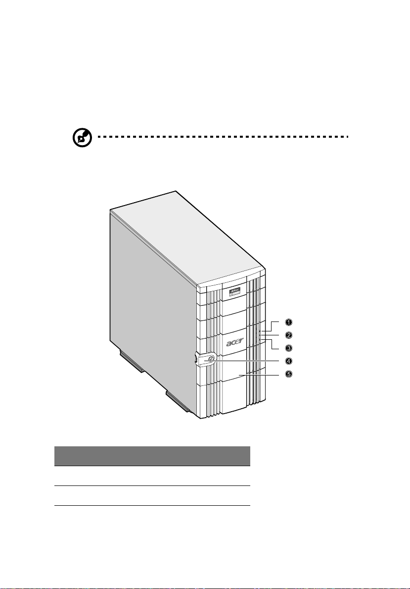
Front panel
Note: One pair of system keys are hung inside the front panel
door. Additional duplicate keys can be found at the back of the
system.
11
No. Item
1Power indicator
2 Hard disk activity indicator
12
No. Item
3 System status indicator
4Keylock
4 Front panel
Rear panel
2 System tour
No. Item No. Item
1 Power indicator 4 Mainboard connectors
2 Power cable connector 5 Monitor port
No. Item No. Item
3 Housing fan 6 Expansion slots
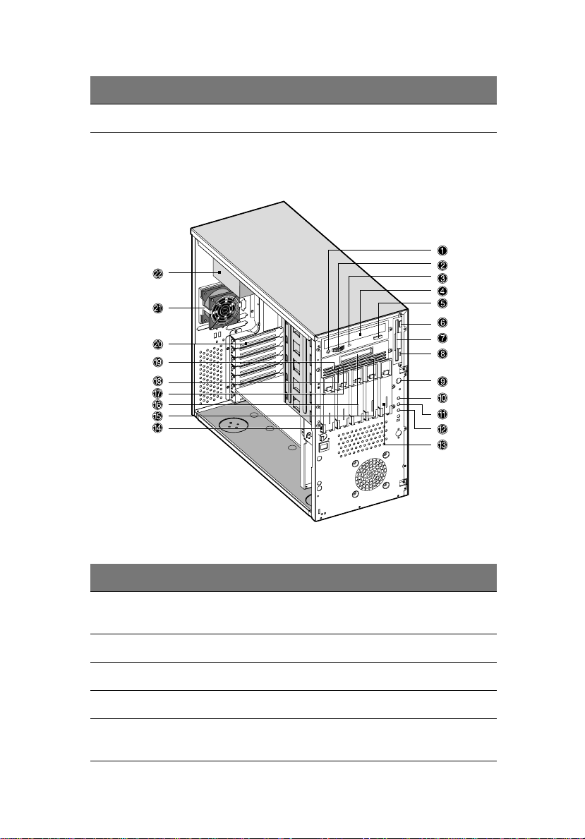
Internal components
13
No. Item No. Item
1 CD-ROM Headphone/
Earphone port
2 Volume tuner 13
3 CD-ROM activity indicator 14 Keylock
4 CD-ROM tray 15 Tape drive eject button
5 CD-ROM Stop/Eject
button
12 System status indicator
16 Tape drive tray

14
No. Item No. Item
6 Floppy drive eject button 17 Drive indicator (amber)
7 Floppy drive tray 18
2 System tour
8 Floppy drive activity
indicator
9 Power button 20
10 Power indicator 21 Housing fan
11 Hard disk activity
indicator
19
22 Power supply

15
Keyboard
Your system comes with a USB keyboard. The keyboard has full-sized
keys that include separate cursor keys, two Windows keys, and twelve
function keys.
No. Component Function
1 Function keys
(F1 - F12)
2 Caps Lock When activated, all alphabetic characters
Access most of the computer’s controls like
screen brightness, volume output and the
BIOS Setup utility.
typed appear in uppercase (same function
as pressing Shift + <letter>).

16
No. Component Function
3 Windows logo key Start button. Combinations with this key
perform special functions, such as:
• Windows + Tab: Activate the next
Taskbar button
• Windows + E: Explore My Computer
• Windows + F: Find Document
• Windows + M: Minimize All
• Shift + Windows + M: Undo Minimize All
• Windows + R: Displays the Run dialog box
2 System tour
4 Application key
5 Cursor keys Also called the arrow keys. These keys let
6 Palm rest
(detachable)
7 Num Lock When activated, the keypad is set to
8 Scroll Lock When activated, the screen moves one line
9 Volume control/
Mute knob
Opens the applications context menu
(same function as clicking the right button
of the mouse).
you move the cursor around the screen.
They serve the same function as the arrow
keys on the numeric pad when the Num
Lock is toggled off.
Provides a comfortable place to rest your
hands while typing.
numeric mode, i.e., the keys function as a
calculator (complete with arithmetic operators such as +, -, x, and /).
up or down when you press the up arrow
or down arrow respectively. Take note
that Scroll Lock may not work with some
applications.
The volume control/mute knob controls
the speaker volume. Turn it clockwise or
counterclockwise to adjust the volume.
Press it to toggle between mute and
sound.
No. Component Function
10 Multimedia keys Allow you to do the following:
• Play/Pause button - press
to start playing the audio or video
file. Press again to pause.
• Stop button - press to stop playing the audio or video file.
• Forward button - press to skip
forward to the next file and start
playing.
• Backward button - press to skip
backward to the previous file and
start playing.
17
11 Internet/Suspend
keys
12 Programmable keys Access a URL (Web site) or launch any pro-
Consist of three buttons:
• Email button launches your
email application.
• Web browser button
launches your current default
browser.
• Suspend/Resume button
puts the system to sleep when
pressed. To wake the system press it
again.
gram, file or application in your system.
The fifth key is set to launch the Windows
Media Player.
To configure the settings of each key,
right-click on the Magic Keyboard icon
located on your Windows desktop.
18
2 System tour
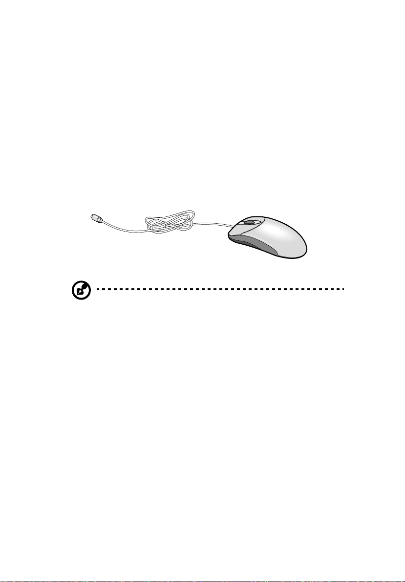
Mouse
Your PS/2 mouse has one ratchet wheel and two buttons: a left button
and a right button. Quickly pressing and releasing the buttons is called
clicking. Sometimes, you will need to do a double-click (clicking the
same button twice quickly) or a right-click (clicking the right button
quickly).
The ratchet wheel in between the two buttons is added to provide
easier scrolling capability . By simply moving the wheel with your index
finger, you can quickly move through multiple pages, lines, or
windows. The wheel may also function as a third button allowing you
to quickly click or double-click an icon or a selected item.
Note: If you are left-handed, refer to your Windows manual for
instructions on how to set up your mouse for left-handed use.
Disk drives
Your system comes with the following disk drives:
3.5-inch floppy drive
Your system’s 3.5-inch floppy drive can handle 720-KB and 1.44-MB
capacity diskettes.
Floppy diskettes are compact, lightweight, and easy to carry around.
Here are some tips on how to take care of your diskettes:
• Always make backup copies of the diskettes that contain
important data or program files.
• Keep diskettes away from magnetic fields and sources of heat.
• Avoid removing a diskette from the floppy drive when the drive
activity indicator is on.
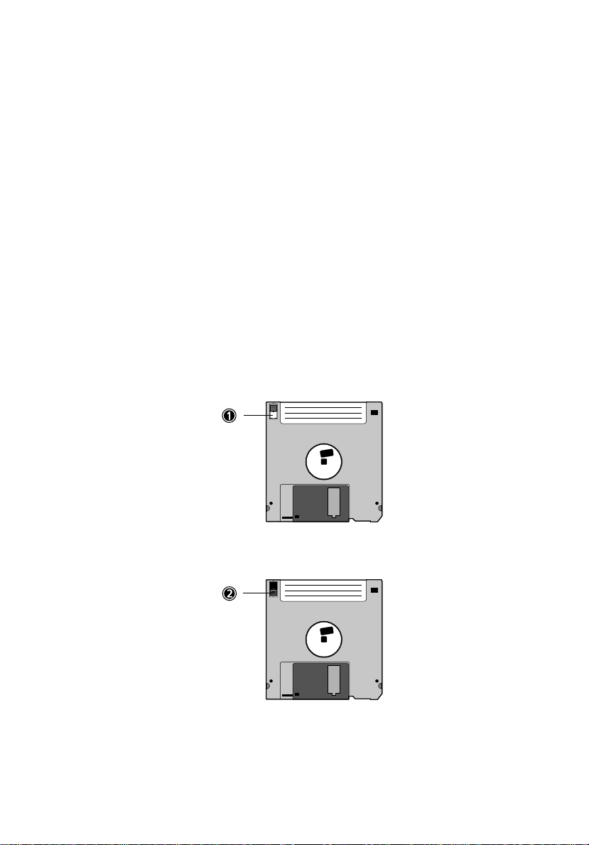
• Write-protect your diskettes to prevent accidental erasure. To do
this, slide the write-protect tab to the write-protect position (1).
19
Sliding the write-protect tab to the not-write-protect position (2)
will allow you to store and modify data in your diskettes.
• When you put a label on a 3.5-inch diskette, make sure that the
label is properly attached (flat on the surface) and within the
labeling area (area with a slight surface depression) on the

20
diskette. An improperly attached label may cause a diskette to get
stuck in the floppy drive when you are inserting or removing it.
2 System tour
CD-ROM drive
Your system comes with a CD-ROM drive. This drive is located on the
front panel of your system. The CD-ROM drive allows you to play
different types of compact discs (CDs) and video CDs.
CDs, like diskettes, are also compact, lightweight, and easy to carry
around. However, they are more delicate than diskettes and must be
handled with extra care.
To insert a CD into your system’s CD-ROM drive:
1 Gently push the eject button located on the front panel.
2 When the disc tray slides open insert the CD. Make sure that the
label or title side of the disc is facing upward.
Caution! Hold the disc by the edges to avoid leaving smudges or
fingerprints.
3 Push the eject button again to close the tray.
To take care of your CDs:
• Keep your discs in a disk case when not in use to avoid scratches or
other damage. Any kind of dirt or damage can affect the data on
the disc, impair the disc lens reader on the CD-ROM drive, or stop
the system from successfully reading the disc.
• When handling discs, always hold them by the edges to avoid
smudges or fingerprints.
• When cleaning discs, use a clean, dust-free cloth and wipe in a
straight line from the center to the edge. Do not wipe in a circular
motion.
• Clean your CD-ROM drive periodically. You may refer to a cleaning
kit for instructions. Cleaning kits can be purchased in any system
or electronics shop.
 Loading...