

Page 1

Acer Altos G310 Mk2
series
Page 2

Copyright © 2005 Acer Incorporated
All Rights Reserved.
Acer Altos G310 Mk2 series
User's Guide
1st Issue: February 2005
Changes may be made periodically to the information in this publication without obligation
to notify any person of such revisions or changes. Such changes will be incorporated in new
editions of this manual or supplementary documents and publications. This company makes
no representations or warranties, either expressed or implied, with respect to the contents
hereof and specifically disclaims the implied warranties of merchantability or fitness for a
particular purpose.
Record the model number, serial number, purchase date, and place of purchase information in
the space provided below. The serial number and model number are recorded on the label
affixed to your computer. All correspondense concerning your unit should include the serial
number, model number, and purchase information.
No part of this publication may be reproduced, stored in a retrieval system, or transmitted, in
any form or by any means, electronically, mechanically, by photocopy, recording, or otherwise,
without the prior written permission of Acer Incorporated.
Model Number: _________________________________
Serial Number: ___________________________________
Purchase Date: ___________________________________
Place of Purchase: ________________________________
Acer and the Acer logo are registered trademarks of Acer Inc. Other companies' product
names or trademarks are used herein for identification purposes only and belong to their
respective companies.
Page 3

Notices
FCC notice
Class A devices do not have an FCC logo or FCC IDE on the label. Class B devices
have an FCC logo or FCC IDE on the label. Once the class of the device is
determined, refer to the following corresponding statement.
Class B equipment
This device has been tested and found to comply with the limits for a Class B
digital device pursuant to Part 15 of the FCC Rules. These limits are designed to
provide reasonable protection against harmful interference in a residential
installation. This device generates, uses, and can radiate radio frequency
energy, and if not installed and used in accordance with the instructions, may
cause harmful interference to radio communications.
However, there is no guarantee that interference will not occur in a particular
installation. If this device does cause harmful interference to radio or television
reception, which can be determined by turning the device off and on, the user
is encouraged to try to correct the interference by one or more of the following
measures:
• Reorient or relocate the receiving antenna
• Increase the separation between the device and receiver
• Connect the device into an outlet on a circuit different from that to which
the receiver is connected
• Consult the dealer or an experienced radio/television technician for help
iii
Page 4

iv
Notice: Shielded cables
All connections to other computing devices must be made using shielded cables
to maintain compliance with FCC regulations.
Notice: Peripheral devices
Only peripherals (input/output devices, terminals, printers, etc.) certified to
comply with the Class A or Class B limits may be attached to this equipment.
Operation with noncertified peripherals is likely to result in interference to
radio and TV reception.
Caution! Changes or modifications not expressly approved by
the manufacturer could void the user's authority, which is granted
by the Federal Communications Commission, to operate this
server.
Use conditions
This part complies with Part 15 of the FCC Rules. Operation is subject to the
following two conditions: (1) this device may not cause harmful interference,
and (2) this device must accept any interference received, including interference
that may cause undesired operation.
Notice: Canadian users
This Class A/Class B digital apparatus meets all requirements of the Canadian
Interference-Causing Equipment Regulations.
Laser compliance statement
The CD-ROM drive in this server is a laser product. The CD-ROM drive's
classification label (shown below) is located on the drive.
CLASS 1 LASER PRODUCT
CAUTION: INVISIBLE LASER RADIATION WHEN OPEN. AVOID EXPOSURE TO
BEAM.
Page 5

Important safety instructions
Read these instructions carefully. Save these instructions for future reference.
1 Follow all warnings and instructions marked on the product.
2 Unplug this product from the power outlet before cleaning. Use a soft,
moist cloth for cleaning. Do not use liquid cleaners or aerosol cleaners.
3 Do not use this product near water. Do not spill water or any other liquid
on the product
4 Do not place this product on an unstable cart, stand, or table. The product
may fall, causing serious damage to the product.
5 Slots and openings on the back or bottom side of the chassis are provided
for ventilation; to ensure reliable operation of the product and to protect
it from overheating, these openings must not be blocked or covered. The
openings should never be blocked by placing the product on a bed, sofa,
rug, or other similar surface. This product should never be placed near or
over a radiator or heat register, or in a built-in installation unless proper
ventilation is provided.
6 This product should be operated from the type of power source indicated
on the label. If you are unsure of the type of power source available,
consult your dealer or local power company before use.
7 Do not allow anything to rest on the power cord. Carefully route the
power cord and any cables away from foot traffic.
8 If an extension cord is used with this product, make sure that the total
ampere rating of the equipment plugged into the extension cord does not
exceed the extension cord ampere rating. Also, make sure that the total
rating of all products plugged into the wall outlet does not exceed the fuse
rating.
9 Never push objects of any kind into this product through chassis slots as
they may touch dangerous voltage points or short out parts that could
result in a fire or electric shock.
10 Do not attempt to service this product yourself, as opening or removing
covers may expose you to dangerous voltage points or other risks. Refer all
servicing to qualified service personnel.
11 Unplug this product from the wall outlet and refer servicing to qualified
service personnel under the following conditions:
a When the power cord or plug is damaged or frayed
b If liquid has been spilled into the product
c If the product has been exposed to rain or water
v
Page 6

vi
d If the product does not operate normally when the operating
instructions are followed. Adjust only those controls that are covered
by the operating instructions since improper adjustment of other
controls may result in damage and will often require extensive work
by a qualified technician to restore the product to normal condition.
e If the product has been dropped or the cabinet has been damaged
f If the product exhibits a distinct change in performance, indicating a
need for service.
12 Replace the battery with the same type as the product's battery we
recommend. Use of another battery may present a risk of fire or explosion.
Refer battery replacement to a qualified service technician.
13 Warning! Batteries may explode if not handled properly. Do not
disassemble or dispose of them in fire. Keep them away from children and
dispose of used batteries promptly.
14 Use only the proper type of power supply cord set (provided in your
accessories box) for this unit. It should be a detachable type: UL listed/CSA
certified, type SPT-2, rated 7A 125V minimum, VDE approved or its
equivalent. Maximum length is 15 feet (4.6 meters).
Page 7

Notices iii
FCC notice iii
Class B equipment iii
Laser compliance statement iv
Important safety instructions v
1 System information 1
Product briefing 3
Processor 3
Memory subsystem 3
Storage 4
Graphics interface 4
Networking 4
I/O ports 4
Serial ATA ports 4
PCI I/O 4
Caring features 5
Product specification summary 7
2 System tour 9
System board 11
Mainboard layout 11
Jumper settings and CMOS clear 13
External and internal structure 14
Front bezel 14
Front panel 16
Rear panel 18
Internal components 20
Contents
3 Getting Started 21
Setting up the system 23
Preinstallation requirements 23
Selecting a site 23
Checking the package contents 23
System startup 24
Turning on the system 24
Turning off the system 25
Power-on problems 25
4 Configuring the system 27
Upgrading the system 29
Installation precautions 29
Page 8

ESD precautions 29
Preinstallation instructions 30
Post-installation instructions 30
Opening the server 31
Before opening the server 31
To remove the side panel 32
To remove the front panel 33
Installing and removing storage devices 34
To install a 5.25-inch storage device 34
Installing and replacing the processor 36
To install the Processor 36
To install the processor fan heat sink 39
Connecting the processor fan heat sink cable 39
To remove a Processor 40
Upgrading the system memory 41
Memory configuration 41
To remove a DIMM 43
To install a DIMM 44
Reconfiguring the system memory 44
Installing an expansion card 45
To install an expansion card 45
Installing and removing a hard disk 47
To remove a hard disk 47
To install a hard disk 47
Contents
5 BIOS setup 49
BIOS setup 51
Entering BIOS setup 52
Main 54
Advanced 55
PCI Configuration 56
Boot Configuration 57
Peripheral Configuration 58
Drive Configuration 59
Floppy Configuration 61
Event Log Configuration 62
Video Configuration 63
USB Configuration 64
PCI Express Configuration 65
Chipset Configuration 66
Fan Control Configuration 67
Hardware Monitoring 68
Remote Access Configuration 69
Page 9

Security 70
Power 71
Boot 72
Boot Device Priority 73
Hard disk Drives 74
Removable Devices 75
ATAPI CD-ROM Drives 76
Exit 77
6 Troubleshooting 79
Troubleshooting 81
Resetting the system 81
Problems following initial system installation 82
First steps checklist 82
Hardware diagnostic testing 83
Verifying proper operation of key system lights 84
Confirming loading of the operating system 84
Specific problems and corrective actions 84
Power light does not light 85
No characters appear on screen 86
Characters are distorted or incorrect 87
System cooling fans do not rotate properly 87
Floppy disk drive activity light does not light 88
CD-ROM drive or DVD-ROM drive activity light does
not light 88
Cannot connect to a server 88
Problems with the network 89
The server hangs when the drivers are loaded. 89
Diagnostics pass but the connection fails. 89
The controller stopped working when an add-in
adaptor was installed. 89
The add-in adaptor stopped working without
apparent cause. 89
System boots when installing PCI card 90
Problems with newly installed application software 90
Problems with application software that ran correctly
earlier 90
Devices are not recognized under device manager
(Windows Operating System) 91
Hard drive(s) are not recognized 91
Bootable CD-ROM is not detected 92
LED information 93
BIOS POST Beep Codes 95
Page 10

BIOS Beep Codes 95
BIOS Error Messages 95
Appendix A: Embedded SATA RAID
Technology for the Altos G310 Mk2 99
SATA ports 101
BIOS Features 101
Driver Features 102
Manageability/Disk console 102
Configuring arrays 104
Configuration strategies 104
Assigning RAID levels 104
Performing a quick configuration 105
Configuring arrays and logical drives 106
Starting the BIOS configuration utility 106
Selecting a configuration method 106
Configuring physical arrays and logical drives 106
Physical drive parameters 106
Logical drive parameters 107
Easy configuration 107
Configuration menu screen 108
Logical drive configuration screen 109
New configuration and view/add configuration 109
Initializing logical drives 111
Logical drive submenu 112
Rebuilding failed disks 112
Inserting a previously removed drive from a
RAID 1 array 113
Checking data consistency 113
Troubleshooting 115
Problems and suggested solutions 115
Contents
Appendix B: Configuring SCSI/SCSI RAID HBA 117
Configuring the SCSI/SCSI RAID HBA 119
How to use SCSI HBA setup utility 119
Loading HBA default settings 119
How to use SCSI RAID HBA setup utility 119
How To Create RAID 1 (Mirror) volume with a
Hot Spare Disk 119
RAID volume initialization 120
Exit and Restart the server 120
MegaRAID configuration utility 121
Load RAID card default setting 121
Page 11

Create RAID1 volume 121
Assign hot spare disk 122
Initialize RAID volume 122
Save and exit MegaRAID configuration utility 122
Page 12

Contents
Page 13

1 System
information
Page 14

The Acer Altos G310 Mk2 server is an entry
level single-processor general purpose
system. The system offers a new standard for
flexible productivity ideal for small business
or workgroup applications.
Page 15
Product briefing
This section provides basic information concerning the configuration of your
Altos G310 Mk2 system.
Processor
• Support for an Intel Pentium 4 processor in an LGA775 socket
• Intel Pentium 4 Processors Extreme Edition
• Intel Pentium 4 Processors
• Intel Celeron D Processors
• 800 and 533 MHz system bus
• Intel Hyper-Threading Technology support
• Intel EM64T support
Memory subsystem
• Four (240 - pin) DIMM slots
• DDR2 400/533 MHz unbuffered ECC memory modules supported
• Dual memory channel support
• Maximum upgrade - 4 GB
• Two-way interleaving support
3
Warn ing! Functionality issues may be encountered if mixed memory types
are installed on the same server board. DIMM modules of identical type,
banking and stacking technology, and vendor should be installed in the
Altos G310 Mk2.
Caution! When using multiple memory modules it is recommended that
you AVOID using modules from different manufacturers or that run at
different speeds from each other.
The table below shows the relationship between processor type and
memory speed.
CPU FSB (MHz) Memory Type Memory Speed (MHz)
Pentium 4 800 DDR2 400 400
800 DDR2 533 533
Celeron D 533 DDR2 400 400
533 DDR2 533 400
Page 16

4
1 System information
Storage
• 5.25 inch IDE CD-ROM drive
• 3.5 inch Floppy disk drive
• Support for three (max) hard disk drives
• Three additional 5.25 inch device bays for add-on options such as:
• DAT72 36/72 GB tape backup drive
• AIT1 35/91 GB tape backup drive
• DVD-ROM, DVD-RW, DVD-Dual or other optical drive
Graphics interface
• Integrated PCI Express™ x8 graphics controller
Networking
• Integrated dual-port Ethernet
•Marvell
•Intel
®
88E8050 Gigabit Ethernet LAN controller
®
82551QM 10/100 Ethernet LAN controller
I/O ports
•Front
• Two USB 2.0 ports
• Rear
• Four USB 2.0 ports
• Two PS/2 ports (keyboard/mouse)
• Two LAN ports (RJ-45)
• One parallel port
• One serial port
• One VGA port
Serial ATA ports
• Four Serial ATA ports supporting RAID 0 or RAID 1
PCI I/O
• Six PCI slots
• Three 32-bit/33 MHz PCI slots
• Two x4 PCI Express slots (w/ x1 throughput)
• One x8 PCI Express slot
Page 17

Caring features
Part of Acer's mission, as a company that cares about its end users, is to
provide features that make operation, maintenance, and upgrading
your system simpler and faster. The Altos G310 Mk2 is no exception to
this rule. The following features and options are provided.
• Cost efficient operation in a value oriented package.
• Tool-less design.
• Front accessible USB ports.
• Integrated graphics.
TM
• Acer EasyBUILD
installation.
• Acer Server Manager (ASM) suite of comprehensive management
tools (optional).
(optional) for efficient system setup and
5
Page 18

6
1 System information
Page 19

Product specification summary
Highlighted below are the system's key features:
•Single Intel
technology and EM64T
• 533/800 MHz FSB supports processor speeds from 2.8 GHz to 3.8
GHz or higher
•Intel
•Intel
•Intel
• Four DIMM sockets supporting DDR2 400/533 MHz ECC modules
for a maximum memory capacity of 4 GB
•Intel® E7221MC GMCH integrated PCI Express x8 Graphics
Controller
• Integrated dual-port Ethernet
•Marvell
•Intel
• Three PCI 32-bit/33 MHz slots
• Two PCI Express x4 slot (with x1 throughput)
• One PCI Express x8 slot
• Media storage
• One 3.5 inch, 1.44 MB floppy drive
• One 5.25 inch high speed CD-ROM drive
• Additional media storage capacity
• Support for three 3.5 inch S-ATA or SCSI hard disk drives
• Three additional 5.25 inch half-height bays
• External ports
• PS/2-compatible keyboard and
• Six USB ports (2 front, 4 rear) • Parallel/printer port
• Two LAN ports • One VGA port
®
Pentium® 4 processor supporting Hyper-Threading
®
7221 Chipset
®
E7221MC Memory Controller Hub (GMCH)
®
82801FR I/O Controller Hub (ICH6-R)
®
88E8050 Gigabit Ethernet LAN controller
®
82551QM 10/100 Ethernet LAN controller
• One serial port
mouse ports
7
• Power supply unit (PSU)
• One 350W ATX12, auto-switching power supply
Page 20

8
1 System information
• Operating Systems supported
®
• Microsoft
•Red Hat
Windows® Server 2003
®
Enterprise Linux 3.0
• Novell Netware 6.5
Page 21

2 System tour
Page 22

This chapter provides locations of various
components and ports, and instructions on how
to set up the system. Procedures on how to
connect peripherals are also explained.
Page 23
11
System board
Mainboard layout
The mainboard becomes accessible once you open the system. It should
look like the figure shown below
II
A
BCDEFGH
HH
I
Z
AABBCCDDEEFFGG
Y
J
X
UV
W
Item Description
A
B
C PCI Express x4 (w/ x1 throughout) slot 2
D PCI Express x4 (w/ x1 throughout) slot 1
E Intel 82551QM LAN controller
F PCI 32-bit/33 MHz slot 2
G PCI 32-bit/33 MHz slot 1
H Marvell 88E8050 PCI Express Gigabit Ethernet Controller
PCI 32-bit/33 MHz slot 3
Rear fan connector
K
L
M
N
O
P
Q
R
S
T
I PCI Express x8 slot 1
J Back Panel I/O
K
Two x 4 power connector
Page 24

12
Item Description
L V reg fan connector
M CPU socket
2 System tour
N
O
P
Q
R
S
T
U
V
W
X
Y
Z
AA
BB
CC
DD
EE
FF
GG
HH
II
CPU fan connector
Hardware Management controller
Intel E7221MC GMCH
Channel A DIMM 0 (Blue) Socket
Channel A DIMM 1 (Black) Socket
Channel B DIMM 0 (Blue) Socket
Channel B DIMM 1 (Black) Socket
I/O controller
Floppy disk drive connector
Two x12 Power connector
Parallel ATA IDE connector
CMOS battery
Chassis intrusion connector
BIOS configuration jumper
Clear CMOS jumper
Front fan connector
Serial ATA connectors
Front panel USB connectors
Serial B connector
SCSI status LED connector
Front panel connector
Intel 82801FR ICH6R I/O Controller Hub
Page 25
Jumper settings and CMOS clear
31
J6J3
Function/Mode Jumper setting Configuration
Normal 1-2 The BIOS uses current configuration
Configure 2-3 After the POST runs, Setup runs
13
Recovery None The BIOS attempts to recover the BIOS
13
information and passwords for
booting.
automatically. The maintenance menu
is displayed.
configuration. A recovery floppy disk is
required.
13
Function/Mode Jumper Setting Configuration
Normal 1-2 The BIOS uses current configuration
1
Clear CMOS 2-3 During POST, the CMOS configuration
13
No Jumper None Normal operation, BIOS uses current
13
3
information.
is reset to default values.
configuration information.
Page 26
14
External and internal structure
Front bezel
Note: One pair of system keys are provided (attached to the rear
panel of the system).
2 System tour
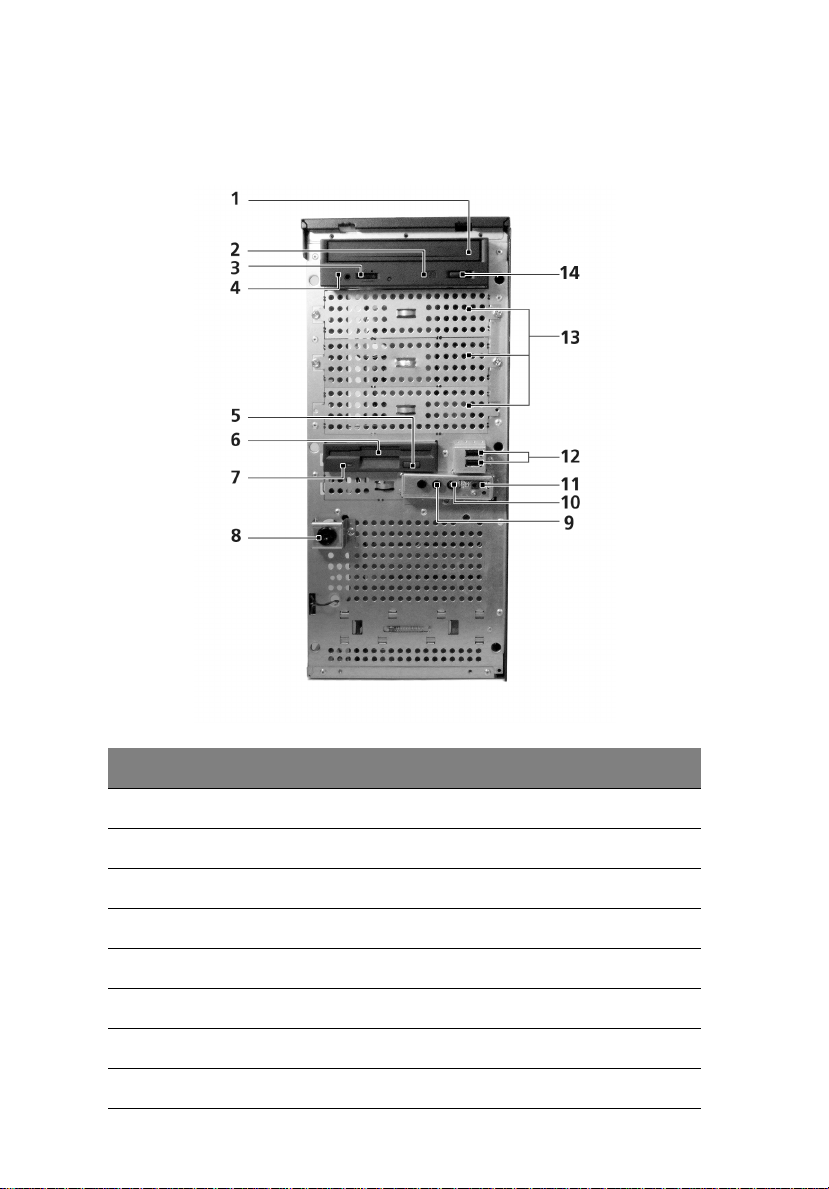
No. Description
1 CD-ROM drive
2 CD-ROM headphone port
3 CD-ROM volume control
4 CD-ROM activity indicator
Page 27

No. Description
5 FDD eject button
6 FDD (floppy disk drive)
7 FDD activity indicator
8 Security keylock
9 HDD activity indicator
10 System power indicator
11 System power button
12 USB 2.0 ports (two)
13 5.25-inch device bays
14 CD-ROM stop/eject button
15
Page 28
16
Front panel
2 System tour
No. Description
1 CD-ROM drive
2 CD-ROM headphone port
3 CD-ROM volume control
4 CD-ROM activity indicator
5 FDD eject button
6 FDD (floppy disk drive)
7 FDD activity indicator
8 Security keylock
Page 29

No. Description
9 HDD activity indicator
10 System power indicator
11 System power button
12 USB 2.0 ports (two)
13 5.25-inch device bays
14 CD-ROM stop/eject button
17
Page 30
18
Rear panel
2 System tour
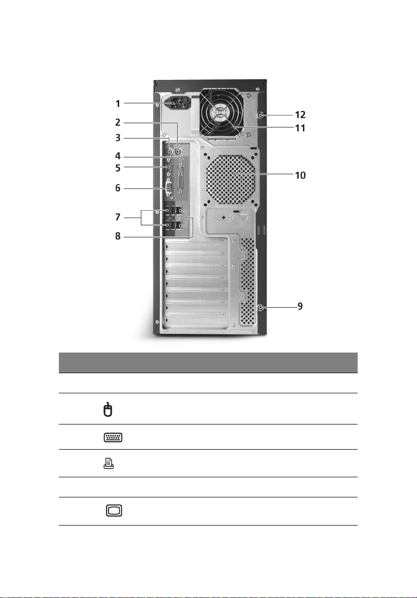
No. Icon Description
1 Main power supply unit
2PS/2 mouse port
3 PS/2 keyboard port
4 Parallel/printer port
5 Serial port
6 VGA port
Page 31

No. Icon Description
7 USB 2.0 ports (four)
8LAN ports
9 Side panel tool-less screws (bottom)
10 System ventilation/fan exhaust
11 Main power supply fan-exhaust
12 Side panel tool-less screws (top)
19
Page 32

20
Internal components
2 System tour
No. Description
1 Power supply unit
2 System fan
3 Mainboard
4PCI slots
5 HDD bays
6 3.5” device bays
7 5.25” device bays
Page 33

3 Getting Started
Page 34

This chapter gives information on setting up
and starting to use your system
Page 35

Setting up the system
Preinstallation requirements
Selecting a site
Before unpacking and installing the system, select a suitable site for
the system for maximum efficiency. Consider the following factors
when choosing a site for the system:
• Near a grounded power outlet
• Clean and dust-free
• Stable surface free from vibration
• Well-ventilated and away from sources of heat
• Secluded from electromagnetic fields produced by electrical
devices such as air conditioners, radio and TV transmitters, etc.
Checking the package contents
Check the following items from the package:
• Acer Altos G310 Mk2 series system
• Acer Altos G310 Mk2 series accessory box
• System keys (attached to the rear panel of the system)
23
If any of the above items are damaged or missing, contact your local
Acer dealer immediately.
Save the boxes and packing materials for future use.
Page 36

24
3 Getting Started
System startup
Turning on the system
After making sure that you have set up the system properly and
connected all the required cables, you can now power on the system.
To power on the system, press the power button on the front panel.
The system starts up and displays a welcome message. After that, a
series of power-on self-test (POST) messages appears. The POST
messages indicate if the system is running well or not.
Note: If the system does not turn on or boot after pressing the
power button, go to the next section for the possible causes of the
boot failure.
Aside from the POST messages, you can determine if the system is in
good condition by checking if the following occurred:
• Power indicator on the front panel lights up (green)
• Num Lock, Caps Lock, and Scroll Lock indicators on the keyboard
light up
Page 37

Turning off the system
To turn off the server, on the Windows task bar click on the Start
button, point to Shut Down..., select Shut down from the dropdown window then click on OK. You can then turn off all peripherals
connected to your server.
If you are unable to shutdown the server within Windows, press and
hold the power button for at least four seconds to force quit all
applications and shut down.
Power-on problems
If the system does not boot after you have applied power, check the
following factors that might have caused the boot failure.
• The external power cable may be loosely connected.
Check the power cable connection from the power source to the
power cable socket on the rear panel. Make sure that the cable is
properly connected to the power source and to the power cable
socket.
• No power comes from the grounded power outlet.
Have an electrician check your power outlet.
• Loose or improperly connected internal power cables.
Check the internal cable connections. If you are not confident to
perform this step, ask a qualified technician to assist you.
25
Warning! Make sure all power cords are disconnected from the
electrical outlet before performing this task.
Note: If you have gone through the preceding actions and the
system still fails to boot, ask your dealer or a qualified technician
for assistance.
Page 38

26
3 Getting Started
Page 39

4 Configuring
the system
Page 40

This chapter discusses the precautionary measures
and installation procedures you need to know when
upgrading the system.
Page 41

Upgrading the system
Certain components of the server are upgradeable such as the drives,
the CPU, the memory, and the expansion cards. However, for safety
purposes, we do not recommend that you perform these upgrades
yourself. If you want to replace or upgrade any of these components,
contact your dealer or a qualified service technician for assistance.
Important: Observe the installation precautions described in the
subsequent section when installing or removing a server
component.
Installation precautions
Before you install any server component, we recommend that you read
the following sections. These sections contain important ESD
precautions along with preinstallation and post-installation
instructions.
ESD precautions
Electrostatic discharge (ESD) can damage the processors, motherboard,
disk drives, expansion boards, or other components. Always observe
the following precautions before you install a server component:
1 Do not remove a component from its protective packaging until
you are ready to install it.
2 Wear a wrist grounding strap and attach it to a metal part of the
server before handling components. If a wrist strap is not
available, maintain contact with the server throughout any
procedure requiring ESD protection.
29
Page 42

30
4 Configuring the system
Preinstallation instructions
Always observe the following before you install any component:
1 Turn off the system and all the peripherals connected to it.
2 Unplug all cables from the power outlets.
3 Open the system according to the instructions on "Opening the
server" on page 31.
4 Follow the ESD precautions described in this section when
handling a server component.
5 Remove any expansion board(s) or peripheral(s) that block access
to the DIMM socket or other component connector.
See the following sections for specific installation instructions on the
component you want to install.
Warning! Failure to properly turn off the server before you start
installing components may cause serious damage. Do not attempt
the procedures described in the following sections unless you are
a qualified service technician.
Post-installation instructions
Observe the following after installing a server component:
1 See to it that all components are installed according to the
described step-by-step instructions.
2 Reinstall any expansion board(s) or peripheral(s) that you have
previously removed.
3 Reinstall the chassis panels.
4 Connect the necessary cables.
5 Turn on the system.
Page 43

Opening the server
Caution! Before you proceed, make sure that you have turned
off your system and all peripherals connected to it. Read the
"Preinstallation instructions" on page 30.
You need to open the server before you can install additional
components. The front and left side panels are removable to allow
access to the system's internal components. Refer to the following
sections for instructions.
Before opening the server
Before opening the server, observe the following precautions:
1 Turn off the system and all the peripherals connected to it.
2 Unplug all cables from the power outlets.
3 Place the system unit on a flat, stable surface.
Note: Because of the G310 Mk2 design specification, only the side
panel needs to be removed to access the system board.
31
Page 44

32
4 Configuring the system
To remove the side panel
The side panel is attached to the server by two (non-removable)
thumbscrews.
To remove the side panel:
1 Locate the System Keys (if necessary) and unlock the system lock
on the front panel.
2 Loosen the thumbscrews located at the rear end of the left panel
(1).
3 Slide the left panel rearward (2) before detaching it from the
chassis.
Page 45

To remove the front panel
The front bezel is attached to the chassis by screwless hinges. To
remove the front panel, you must remove the side panel first.
To remove the front bezel:
1 With your finger, pull the front panel release lever located at the
bottom front inside the chassis (1).
2 Gently pull the bottom of the front bezel away from the chassis
(2), lift it to approximately 45 degrees, then detach the top and
move it away from the chassis.
33
Page 46

34
4 Configuring the system
Installing and removing storage devices
The system supports 3.5-inch and 5.25-inch internal storage devices.
The system comes pre-installed with a floppy drive and a CD-ROM
drive. The empty 5.25-inch half-height bays allow you to install
additional drives such as another CD-ROM drive or a tape drive.
To install a 5.25-inch storage device
Note: If you are installing a new drive in an empty drive bay, skip
steps 2 to 4.
1 Observe the ESD precautions and pre-installation procedures
described on page 30.
2 Disconnect the power and IDE cables from the old drive.
3 Lift the plastic tab that secures the drive in the bay (1) and gently
pull it from the chassis (2).
Page 47

35
4 Transfer the left side tool-less locking rail (looking from the front)
from the old drive to the new drive module.
5 Insert the new CD-ROM drive into the drive bay until it locks into
place with an audible "click."
6 Connect the power and IDE cables to the new drive.
7 Observe the post-installation instructions described on page 30.
Page 48

36
4 Configuring the system
Installing and replacing the processor
This section includes instructions for removing and installing a CPU.
Caution: Processor must be appropriate. You may damage the
server board if you install a processor that is inappropriate for
your server.
Caution: SD and handling processors. Reduce the risk of
electrostatic discharge (ESD) damage to the processor by doing
the following: (1) Touch the metal chassis before touching the
processor or server board. Keep part of your body in contact with
the metal chassis to dissipate the static charge while handling the
processor. (2) Avoid moving around unnecessarily.
To install the Processor
Caution: Before installing or removing the processor, make sure
that AC power has been removed by unplugging the power cord
from the computer; the standby power LED should not be lit.
Failure to do so could damage the processor and the board.
To install a processor, follow these instructions:
Before you start, please observe the ESD precautions on page 29.
1 Open the socket lever by pushing the lever down and away from
the socket.
Page 49

2 Lift the load plate. Do not touch the socket contacts.
3 Remove the protective socket cover from the load plate. Do not
discard the protective socket cover. Always replace the socket
cover if the processor is removed from the socket.
37
4 Remove the processor from the protective processor cover. Hold
the processor only at the edges, being careful not to touch the
bottom of the processor. Do not discard the protective processor
cover. Always replace the processor cover if the processor is
removed from the socket.
Page 50

38
4 Configuring the system
5 Hold the processor with your thumb and index fingers oriented as
shown below. Make sure fingers align to the socket cutouts. Align
notches with the socket. Lower the processor straight down
without tilting or sliding the processor in the socket.
6 Pressing down on the load plate close and engage the socket lever.
Page 51

To install the processor fan heat sink
The Altos G310 Mk2's server board has an integrated processor fan
heat sink retention mechanism (RM).
Connecting the processor fan heat sink cable
Connect the processor fan heat sink cable to the 4-pin processor fan
header.
39
Page 52

40
4 Configuring the system
To remove a Processor
1 Observe the safety and ESD precautions at the beginning of this
section.
2 Turn off all peripheral devices connected to the server. Turn off
the server.
3 Remove the AC power cord from the server.
4 Remove the server's cover. See the documentation that
accompanied your server chassis for instructions on removing the
server's cover.
5 Unplug the processor fan cable from the server board.
6 Loosen the four captive screws on the corners of the heat sink.
7 Twist the heat sink slightly to break the seal between the heat sink
and the processor.
8 Lift the heat sink from the processor. If it does not pull up easily,
twist the heat sink again. Do not force the heat sink from the
processor. Doing so could damage the processor.
9 Lift the processor lever.
10 Remove the processor.
If installing a replacement processor, see "To install the Processor" on
page 36. Otherwise, reinstall the chassis cover.
Page 53

41
Upgrading the system memory
Memory configuration
This section includes instructions for removing and installing a memory
module.
The memory modules are located on the main server board as shown
below:
Channel A
DIMM 0
DIMM 1
Channel B
DIMM 0
DIMM 1
The two tables (below) summarize the characteristics of 1-way and 2-
way memory interleave configurations.
Memory Channel A Memory Channel B
DIMM0 DIMM1 DIMM0 DIMM1
512 MB 1-way
1 GB
512 MB 512 MB 2-way
1 GB 1 GB
512 MB 512 MB 512 MB 512 MB 2-way
1 GB 1 GB 1 GB 1 GB
Memory
Interleave
Page 54

42
4 Configuring the system
Warning! Functionality issues may be encountered if mixed
memory types are installed on the same server board. DIMM
modules of identical type, banking and stacking technology, and
vendor should be installed in the Altos G310 Mk2.
Page 55

43
To re m ove a D I M M
Before installing a new DIMM in a socket, remove first any previously
installed DIMM from that socket.
Important: Before removing any DIMM from the mainboard,
make sure to create a backup file of all important data.
1 Observe the precautions and pre-installation procedures described
in "ESD precautions" on page 29.
2 Locate the DIMM socket on the mainboard.
3 Press the holding clips on both sides of the socket outward to
release the DIMM (1).
4 Gently pull the DIMM upward to remove it from the socket (2).
Note: Place your forefingers on the top of the DIMM before
pressing the holding clips to gently disengage the DIMM from the
socket.
Page 56

44
4 Configuring the system
To install a DIMM
1 Observe the precautions and pre-installation procedures described
in "ESD precautions" on page 29.
2 Locate the DIMM sockets on the mainboard.
3 Open the clips on the socket.
4 Align then insert the DIMM into the socket (1).
5 Press the holding clips inward to lock the DIMM in place (2).
DIMMs must be installed in the following order: DM1. DM2, DM3 and DM4
Note: The DIMM socket is slotted to ensure proper installation.
If you insert a DIMM but it does not fit easily into the socket, you
may have inserted it incorrectly. Reverse the orientation of the
DIMM and insert it again.
6 Observe the "Post-installation instructions" on page 30.
Reconfiguring the system memory
The system automatically detects the amount of memory installed.
Run the BIOS setup to view the new value for total system memory and
make a note of it.
Page 57

Installing an expansion card
This section explains how to install an expansion card. The onboard
expansion slots support PCI (Peripheral Component Interconnect) or
PCI Express cards.
Note: The BIOS setup automatically detects and assigns resources
to the new device (applicable only to Plug-and-Play expansion
cards).
To install an expansion card
Note: The illustrations used in this section show the Altos G310
Mk2 server chassis.
1 Observe the ESD precautions and pre-installation procedures
described in "ESD precautions" on page 29.
2 Remove the side panel to access the mainboard. See "To remove
the side panel" on page 32 for more information.
3 Locate an empty expansion slot on the mainboard.
4 Remove the tool-less the card bracket lock(1).
5 Pull out the card bracket (2).
45
6 Remove the expansion card from its protective packaging.
Page 58

46
4 Configuring the system
7 Align the card in the empty slot on the mainboard.
8 Insert the bracket with the card into the selected slot (3). Make
sure that the card is properly seated.
9 Secure the card with the tool-less bracket card lock removed in
step three above (4).
10 Observe the "Post-installation instructions" on page 30.
Page 59

Installing and removing a hard disk
Although the Altos G310 Mk2 has four hard disk slots, the system
board only supports a maximum of three.
To remove a hard disk
Follow these steps to replace your computer's hard disk:
1 Remove the side and front panels (see page 32 and page 33).
2 Detach the cables from the exposed end of the HDD (1) and (2).
3 Squeeze the two locking tabs that secure the drive to the chassis
slot and gently remove the HDD from the system (3).
47
3
1
To install a hard disk
Observe the pre-installation and ESD precautions on page 29. Follow
these steps to replace your computer's hard disk:
Page 60

48
4 Configuring the system
1 Remove the side panel (see page 32).
2 Attach the HDD rails to the sides of the drive housing as shown
below.
3 Insert the drive into an empty HDD slot (slot 1 or slot 3) until it
locks into place with an audible “click” (1).
4 Attach the power and IDE cables to the HDD (2) and (3)..
Page 61

5 BIOS setup
Page 62

This chapter gives information about the
system BIOS and discusses how to configure
the system by changing the settings of the
BIOS parameters.
Page 63

51
BIOS setup
BIOS setup is a hardware configuration program built into your
system's Basic Input/Output System (BIOS). Since most systems are
already properly configured and optimized, there is no need to run this
utility. You will need to run this utility under the following conditions:
• When changing the system configuration
• When a configuration error is detected by the system and you are
prompted ("Run Setup" message) to make changes to the BIOS
setup
Note: If you repeatedly receive Run Setup messages, the
battery may be bad. In this case, the system cannot retain
configuration values in CMOS. Ask a qualified technician
for assistance.
• When redefining the communication ports to prevent any conflicts
• When making changes to the Power Management configuration
• When changing the password or making other changes to the
security setup
BIOS setup loads the configuration values in a battery-backed
nonvolatile memory called CMOS RAM. This memory area is not part
of the system RAM which allows configuration data to be retained
when power is turned off.
Before you run BIOS setup, make sure that you have saved all open
files. The system reboots immediately after you close setup.
Page 64

52
5 BIOS setup
Entering BIOS setup
Power on the server to start the system POST (Power On Self Test)
process. During bootup, press F2 to enter the BIOS setup screen.
Note: You must press F2 while the system is booting. This
key combination does not work during any other time.
There are several tabs on the setup screen corresponding to the six
major BIOS menus:
•Main
•Advanced
•Security
•Power
•Boot
• Exit
The parameters on the screens shown in this User's Guide display
default system values. These values may not be the same as those in
your system.
Note the following reminders when moving around the setup screen:
• Use the Left and Right arrow keys to move to the next page or to
return to the previous screen.
• Use the Up and Down arrow keys to select an item.
• Use the + and - keys to select an option.
Note: You can configure a parameter that is enclosed in
square brackets. Grayed-out items have fixed settings and
are not user-configurable.
• Use the Ta b key to select a field.
Page 65

53
• Use the Enter key to display a submenu screen.
Note: When a parameter is preceded by a (>), it means
that a submenu screen is available.
• Press F1 for General Help on using the BIOS setup.
• Press F9 to set up defaults
• Press F10 to save changes and close the BIOS setup.
• Press Esc to close the BIOS setup.
In the descriptive table following each of the screen illustrations,
settings in boldface are the default and suggested parameter settings.
Page 66

54
5 BIOS setup
Main
The Main menu displays basic and important information about the
system. This information is necessary for troubleshooting and may be
required when asking for technical support.
The last parameter on the screen lets you define the system's time and
date settings. The real-time clock keeps the system date and time.
After setting the date and time, you do not need to enter them every
time you turn on the system. As long as the internal battery remains
good and connected, the clock continues to keep the date and time
accurately even when the power is off.
BIOS SETUP UTILITY
Main Advanced Security Power Boot Exit
BIOS Version : BA92510A.86B.0149
Processor Type : Genuine Intel(R) CPU
Hyper-Threading Technology : [Enabled]
Processor Speed 3.6 GHz
System Bus Speed 800 M Hz
System Memory Speed 533 MHz
Memory Mode Dual Channel
Memory Channel A Slot 0 1024 MB
Memory Channel A Slot 1 1024 MB
Memory Channel B Slot 0 1024 MB
Memory Channel B Slot 1 1024 MB
? Additional System Information
Memory Correction [ECC]
Language [English]
System Time [19:32:56]
▲
▼
Select Screen
←→
Select Item
↑↓
Enter Select ? Sub-Menu
Tab Select Field
F1 General Help
F9 Setup Defaults
F10 Save and Exit
ESC Exit
Parameter Description Option
Hyper-Threading
Technology
Additional System
Information
Memory Correction Memory correction selection Non-ECC
System Time Configures the system time on a 24
Enable Hyper-Threading Technology
only if OS supports it
Display the system information
hour clock. Default is 00:00:00
Enabled
Disabled
ECC
HH:MM:SS
Page 67

Advanced
The Advanced menu contains parameter values that define how the
system behaves on startup.
Important! Be cautious in setting parameter values in the
Advanced menu as any incorrect value may cause the system to
malfunction.
Press Enter to enter the submenu screen of the parameters shown in
the screen below
BIOS SETUP UTILITY
Main Advanced Security Power Boot Exit
Setup Warning:
Setting items on this screen to incorrect values
may cause the system to malfunction!
? PCI Configuration
? Boot Configuration
? Peripheral Configuration
? Drive Configuration
? Floppy Configuration
? Event Log Configuration
? Video Configuration
? USB Configuration
? PCI Express Configuration
? Chipset Configuration
? Fan Control Configuration
? Hardware Monitoring
? Remote Access Configuration
PCI Configuration
Select Screen
←→
Select Item
↑↓
Enter Select ? Sub-Menu
Tab Select Field
F1 General Help
F9 Setup Defaults
F10 Save and Exit
ESC Exit
55
Page 68

56
PCI Configuration
Advanced
PCI Configuration
PCI Slot1 IRQ Priority [Auto]
PCI Slot2 IRQ Priorit y [Auto]
PCI Slot3 IRQ Priorit y [Auto]
BIOS SETUP UTILITY
5 BIOS setup
Manual IRQ selection
does not guarantee PCI
slot device will be
configured with choice
because PnP ISA cards
( If present ) are assigned
the available resources
before PCI devices
Select Screen
←→
Select Item
↑↓
Enter Select ? Sub-Menu
Tab Select Field
F1 General Help
F9 Setup Defaults
F10 Save and Exit
ESC Exit
Parameter Description Option
PCI Slot N Configuration Sets a parameter for the PCI buses Auto
Page 69

Boot Configuration
BIOS SETUP UTILITY
Advanced
Boot Configuration
Plug & Play O/S [No]
Numlock [On]
Max CPUID Value Limit: [Disabled]
Parameter Description Option
No, lets the BIOS
configure all the devices
in the system. Yes, lets
the operating system
configure Plug and Play
(PnP) devices not
required for boot if your
system has a Plug and
Play operating system
Select Screen
←→
Select Item
↑↓
Enter Select ? Sub-Menu
Tab Select Field
F1 General Help
F9 Setup Defaults
F10 Save and Exit
ESC Exit
57
Plug and Play OS Selects OS that supports PnP features No
Numlock Selects power-on state for Numlock On
Max CPUID Value Limit This should be enabled in order to boot
legacy OSes that cannot support CPUs with
extended CPUID functions
Yes
Off
Enabled
Disabled
Page 70

58
5 BIOS setup
Peripheral Configuration
BIOS SETUP UTILITY
Advanced
Peripheral Configuration
Serial Port A [Auto]
Serial Port B [Auto]
Parallel Port [Auto]]
Mode [Bi-directional]
Onboard Gb LAN [Enabled]
Onboard 10/100 LAN [Enabled]
ASF Support [Enabled]
Parameter Description Option
Select Screen
←→
Select Item
↑↓
Enter Select ? Sub-Menu
Tab Select Field
F1 General Help
F9 Setup Defaults
F10 Save and Exit
ESC Exit
Serial port A Indicates the configuration of serial port A Enabled
Serial port B Indicates the configuration of serial port B Enabled
Parallel port Indicates the configuration of the parallel port Enabled
Disabled
Auto
Disabled
Auto
Disabled
Auto
Page 71

59
Mode Sets the operation mode for the parallel port. When
set to output only, allows normal speed one-way
operation. When Bi-directional, allows normal speed
operation in a two way mode. EPP (Enhanced Parallel
Output only
Bi-directional
EPP
ECP
Port) allows bi-directional parallel port operation at
maximum speed. ECP (Extended Capabilities Port)
allows the parallel port to operate in bi-directional
mode and at a speed higher than the maximum data
transfer rate.
Onboard Gb
LAN
Onboard 10/
100 LAN
Sets onboard Gb LAN Enabled
Disabled
Sets onboard 10/100 LAN Enabled
Disabled
ASF Support Sets ASF support Enabled
Disabled
Drive Configuration
BIOS SETUP UTILITY
Advanced
Drive Configuration
ATA/IDE Configuration [Enhanced]
Intel(R) RAID Technology [Disabled]
SATA AHCI Mode [Disabled]
PCI IDE Bus Master [Enabled]
Hard Disk Pre-Delay [Disabled]
? [SATA Port-0 : :WDC WD1200JD-22GBB0]
? [SATA Port-2 : Not Detected]
? [SATA Port-1 : Not Detected]
? [SATA Port-3 : Not Detected]
? [PATA Master : CD-ROM 52X/AKH]
? [PATA Slave : Not Detected]
Disabled: All IDE
resources disabled
LEGACY: Up to 2 IDE
channels enabled for OS
requiring legacy IDE
operation
ENHANCED: All SATA and
PATA resources enabled
Select Screen
←→
Select Item
↑↓
Enter Select ? Sub-Menu
Tab Select Field
F1 General Help
F9 Setup Defaults
F10 Save and Exit
ESC Exit
Page 72

60
Parameter Description Option
5 BIOS setup
ATA/IDE
Configuration
Intel RAID
Technology
SATA AHCI
Mode
PCI IDE Bus
Master
Hard Disk PreDelay
SATA Port-N Displays the status of auto detection of IDE
PATA Master/
Slave
Disabled: All IDE resources disabled. LEGACY: Up
to 2 IDE channels enabled for OS requiring legacy
IDE operation. ENHANCED: All SATA and PATA
resources enabled
Sets RAID function Enabled
Sets SATA AHCI Mode Enabled
Sets PCI IDE Bus master Enabled
Selects the hard disk drive pre-delay Disabled
devices
Displays the status of auto detection of IDE
devices
Disabled
Legacy
Enhanced
Disabled
Disabled
Disabled
….N seconds
Page 73

Floppy Configuration
BIOS SETUP UTILITY
Advanced
Floppy Configuration
Diskette Controller [Enabled]
Floppy A [1.44 MB 3
Diskette Write Protect [Disabled]
1
/2”]
61
Configures the integrated
diskette controller
Select Screen
←→
Select Item
↑↓
Enter Select ? Sub-Menu
Tab Select Field
F1 General Help
F9 Setup Defaults
F10 Save and Exit
ESC Exit
Parameter Description Option
Floppy disk
controller
Configures the integrated floppy disk
controller
Enabled
Disabled
Floppy A Selects the floppy drive type Disabled
360 KB 5
1.2 MB 51/4”
720 KB 31/2”
1.44 MB 31/2”
2.88 MB 3
Floppy disk
write protect
Disables/Enables floppy disk drive write
protection
Enabled
Disabled
1
/4”
1
/2”
Page 74

62
V
Event Log Configuration
BIOS SETUP UTILITY
Advanced
Event Log Configuration
Event Log [Space Available]
View Event Log
Clear Event Log
Event Logging [Enabled]
ECC Event Logging [Enabled]
Mark Events As Read
5 BIOS setup
iews the contents of the
DMI event log.
Select Screen
←→
Select Item
↑↓
Enter Select ? Sub-Menu
Tab Select Field
F1 General Help
F9 Setup Defaults
F10 Save and Exit
ESC Exit
Parameter Description Option
View Event Log Views the contents of the DMI event log.
Clear Event Log Discards all events in the Event Log
Event Logging Selects Enabled to allow logging of DMI
events
ECC Event Logging Selects Enabled to allow logging of ECC
events
Mark Events As Read Press Enter to mark all DMI events in the
event log as read
Enabled
Disabled
Enabled
Disabled
Page 75

Video Configuration
BIOS SETUP UTILITY
Advanced
Video Configuration
Primary Video Adapter [Auto]
Frame Buffer Size [ 8MB]
IGD Aperture Size [256MB]
DVMT MODE [DVMT]
IGD DVMT/FIXED MEMORY [128MB]
Allows selecting the
Primary Video Adapter
init’d & used by BIOS &
OS for Boot Display
Select Screen
←→
Select Item
↑↓
Enter Select ? Sub-Menu
Tab Select Field
F1 General Help
F9 Setup Defaults
F10 Save and Exit
ESC Exit
63
Parameter Description Option
Primary video
Adaptor
Allows selecting the Primary video adaptor
init'd & used by BIOS & OS for Boot Display
PCIE Graphics(PEG)
Ext PCI Graphics
Auto
Frame Buffer
Size
IGD
Aperature
Size
DVMT MODE Selects IGD OS/Driver memory allocation
Selects how much system RAM is reserved for
use by the internal graphics device
Selects how much memory address space is
allocated in PCI Memory space for use by the
internal graphics device.
method
1MB/4MB/8MB/
16MB/32MB
128MB
256MB
FIXED
DVMT
BOTH
IGD DVMT/
FIXED
Selects IGD OS/Driver memory size used 32MB/64MB/
128MB/Maximum
MEMORY
Page 76

64
USB Configuration
BIOS SETUP UTILITY
Advanced
USB Configuration
High-Speed USB [Enabled]
Legacy USB Support [Enabled]
USB 2.0 Legacy Support [Full-Speed]
5 BIOS setup
Disables this function
when a USB 2.0 driver is
not available
Select Screen
←→
Select Item
↑↓
Enter Select ? Sub-Menu
Tab Select Field
F1 General Help
F9 Setup Defaults
F10 Save and Exit
ESC Exit
Parameter Description Option
High-Speed USB Disables this function when a USB 2.0
Legacy USB Support Supports USBdevices in legacy mode Enabled
USB 2.0 Legacy
Support
driver is not available
Configures the USB 2.0 Legacy support to
HiSpeed (480Mpbs) or FullSpeed (12Mbps)
Enabled
Disabled
Disabled
Full-Speed
Hi-Speed
Page 77

PCI Express Configuration
BIOS SETUP UTILITY
Advanced
PCIE x16 Link Retrain [Disable]
Link Stability Algorithm [Enabled]
Compliance Test Pattern [Disabled]
PEG Negotiated Width None
Parameter Description Option
Select Screen
←→
Select Item
↑↓
Enter Select ? Sub-Menu
Tab Select Field
F1 General Help
F9 Setup Defaults
F10 Save and Exit
ESC Exit
65
PCIE x16 Link
Retrain
Link Stability
Algorithm
Compliance Test
Pattern
Select to retrain PCIE x16 link GFX Card
Enabled
Disabled
Select to enable link stability algorithm Enabled
Disabled
Selects the test pattern for PCI Express Enabled
Disabled
Page 78

66
Chipset Configuration
BIOS SETUP UTILITY
Advanced
Chipset Configuration
Setup Warning:
Setting items on this screen to incorrect values
may cause the system to malfunction!
ISA Enable Bit [Enabled]
PCI Latency Timer [32]
5 BIOS setup
Some older expansion
devices require this to be
enabled
Select Screen
←→
Select Item
↑↓
Enter Select ? Sub-Menu
Tab Select Field
F1 General Help
F9 Setup Defaults
F10 Save and Exit
ESC Exit
Parameter Description Option
ISA Enable Bit Some older expansion devices require this
to be enabled
PCI Latency Timer Sets Latency Timer for PCI bus 32, 64, 96,
Enabled
Disabled
128,160,192,
224,248
Page 79

Fan Control Configuration
BIOS SETUP UTILITY
Advanced
Fan Control Configuration
Note: The new settings will not take effect until the system is
completely shut down
CPU Fan Control [Enabled]
Fan Control [Enabled]
Lowest Fan Speed [Slow]
Enables or disables CPU
fan control
Select Screen
←→
Select Item
↑↓
Enter Select ? Sub-Menu
Tab Select Field
F1 General Help
F9 Setup Defaults
F10 Save and Exit
ESC Exit
67
Parameter Description Option
CPU Fan
Control
Sets CPU fan control Enabled
Disabled
Fan Control Sets system fan control Enabled
Disabled
Lowest Fan
Speed
Selects the lower limit of chassis fan speed
operation. Slow: At low system temperatures the
Slow
Off
fans will continue to run at a slow speed; Off: At
low system temperatures the fans will turn off
Page 80

68
Hardware Monitoring
BIOS SETUP UTILITY
Advanced
Hardware Monitoring
Note: These measurements are approximated and should
not be used for validation purposes
Processor Zone Temperature
System Zone 1 Temperature
System Zone 2 Temperature
Processor Fan Speed 3419 RPM
Vreg Fan Speed 0 RPM
Front Fan Speed 0 RPM
Rear Fan Speed 0 RPM
+1.5Vin 1.493 V
Vccp 1.317 V
+3.3Vin 3.310 V
+5Vin 5.105 V
+12Vin 12.000V
71°C/159°F
36°C/96°F
44°C/111°F
5 BIOS setup
Select Screen
←→
Select Item
↑↓
Enter Select ? Sub-Menu
Tab Select Field
F1 General Help
F9 Setup Defaults
F10 Save and Exit
ESC Exit
Page 81

Remote Access Configuration
BIOS SETUP UTILITY
Advanced
Configure Remote Access type and parameters
Remote Access [Disabled]
Select Remote Access
type
Select Screen
←→
Select Item
↑↓
Enter Select ? Sub-Menu
Tab Select Field
F1 General Help
F9 Setup Defaults
F10 Save and Exit
ESC Exit
69
Parameter Description Option
Remote Access Selects remote access type Enabled
Disabled
Page 82

70
5 BIOS setup
Security
The Security menu allows you to safeguard and protect the system
from unauthorised use by setting up access passwords.
BIOS SETUP UTILITY
Main Advanced Security Power Boot Exit
Supervisor Password : Not Installed
User Password : Not Installed
Set Supervisor Password
Set User Password
Chassis Intrusion [Disabled]
Install or Change the
passw ord
Select Screen
←→
Select Item
↑↓
Enter Select ? Sub-Menu
Tab Select Field
F1 General Help
F9 Setup Defaults
F10 Save and Exit
ESC Exit
Parameter Description Option
Set Supervisor Password Install or change the password
Set User Password Install or change the password
Chassis Intrusion Sets chassis intrusion function Enabled
Disabled
Page 83

Power
The Power menu allows you to configure the system's power
management features.
BIOS SETUP UTILITY
Main Advanced Security Po wer Boot Exit
? ACPI
After Power Failure [Last State]
The options below are not related to ACPI and may be
ignored when shutting down suing an ACPI OS
Wake On PCI PME [Stay Off]
Power Management
options related to ACPI
Select Screen
←→
Select Item
↑↓
Enter Select ? Sub-Menu
Tab Select Field
F1 General Help
F9 Setup Defaults
F10 Save and Exit
ESC Exit
71
Parameter Description Option
ACPI Wake on LAN from S5. Determines the action of
After Power
Failure
Wake on PCI
PME
the system when a PCI Power Management Enable
wake up event occurs
Determines the mode of operation if a power loss
occurs. Stays Off: system will remain off once
power is restored. Power On: boots the system
after power is restored. Last State: restores the
system to the same state it was in before power
failed.
Determines the action taken when the system
power is off and a PCI Power Management Enable
wake up event occurs
Stay Off
Power On
Stay Off
Last State
Power On
Stay Off
Power On
Page 84

72
5 BIOS setup
Boot
The boot menu allows you to specify the preferred settings during
system boot up.
Press <Enter> to enter the submenu screen of the parameters shown in
the screen below.
BIOS SETUP UTILITY
Main Advanced Security Power Boot Exit
Silent Boot [Enabled]
AddOn ROM Display Mode [Enabled]
Intel(R) Rapid BIOS Boot [Enabled]
Scan User Falsh Area [Enabled]
PXE Boot to LAN [Disabled]
USB Boot [Enabled]
?Boot Device Priority
? Hard Disk Drives
? Removable Devices
? ATAPI CD-ROM Drives
Disabled, displays normal
POST messages.
Enabled, displays OEM
Logo instead of POST
messages
Select Screen
←→
Select Item
↑↓
Enter Select ? Sub-Menu
Tab Select Field
F1 General Help
F9 Setup Defaults
F10 Save and Exit
ESC Exit
Parameter Description Option
Silent Boot Disabled, displays normal POST messages. Enabled,
AddOn ROM Display
Mode
Intel Rapid BIOS
Boot
Scan User Flash Area Allows BIOS to scan the Flash ROM for user
displays OEM Logo instead of POST messages
Sets AddOn ROM display mode Enabled
Allows BIOS to skip certain tests while booting. Enabled
binaries
Enabled
Disabled
Disabled
Disabled
Enabled
Disabled
Page 85

73
PXE Boot to LAN Disables or enables PXE boot to LAN Enabled
Disabled
USB Boot Disables or enables booting to USB boot devices Enabled
Disabled
Boot Device Priority
BIOS SETUP UTILITY
Boot
st Boot Device [1st FLOPPY DRIVE]
1
2 nd Boot Device [PM-WDC WD1200JD-22GBB0]
3 rd Boot Device [3M-CD-ROM 52X/AKH]
Specifies the boot
sequence from the
available devices
A device enclosed in
parenthesis in the
corresponding type menu
Select Screen
←→
Select Item
↑↓
Enter Select ? Sub-Menu
Tab Select Field
F1 General Help
F9 Setup Defaults
F10 Save and Exit
ESC Exit
Parameter Description Option
1st Boot Device Sets the device from which the system will first
attempt to boot up
2nd Boot Device Sets the device from which the system will
attempt to boot up when the first attempt
failed
N th Boot Device Sets the device from which the system will
attempt to boot up when the N-1 attempt
failed
Page 86

74
Hard disk Drives
BIOS SETUP UTILITY
Boot
st Device [PM-WDC WD1200JD-22GBB0]
1
5 BIOS setup
Specifies the boot
sequence from the
available devices. Select
the boot device with
UpArrow or Down Arrow
key. Press Enter to set
the selection as the
intended boot device.
ARMD=ATAPI Removable
Media Device
Select Screen
←→
Select Item
↑↓
Enter Select ? Sub-Menu
Tab Select Field
F1 General Help
F9 Setup Defaults
F10 Save and Exit
ESC Exit
Parameter Description Option
1st Device Specifies the boot sequence from the available
devices. Select the boot device with UpArrow or
DownArrow key. Press Enter to set the selection as
the intended boot device.
ARMD=ATAPI Removable Media Device
Page 87

Removable Devices
BIOS SETUP UTILITY
Boot
1
st Device [1 st FLOPPY DRIVE]
Specifies the boot
sequence from the
available devices. Select
the boot device with
UpArrow or DownArrow
key. Press Enter to set
the selection as the
intended boot device.
ARMD=ATAPI Removable
Media Device
Select Screen
←→
Select Item
↑↓
Enter Select ? Sub-Menu
Tab Select Field
F1 General Help
F9 Setup Defaults
F10 Save and Exit
ESC Exit
75
Parameter Description Option
1st Device Specifies the boot sequence from the available
devices. Select the boot device with UpArrow or
DownArrow key. Press Enter to set the selection as
the intended boot device.
ARMD=ATAPI Removable Media Device
Page 88

76
ATAPI CD-ROM Drives
BIOS SETUP UTILITY
Boot
st Device [13M-CD-ROM 52X/AKH]
1
5 BIOS setup
Specifies the boot
sequence from the
available devices. Select
the boot device with
UpArrow or DownArrow
key. Press Enter to set
the selection as the
intended boot device.
ARMD=ATAPI Removable
Media Device
Select Screen
←→
Select Item
↑↓
Enter Select ? Sub-Menu
Tab Select Field
F1 General Help
F9 Setup Defaults
F10 Save and Exit
ESC Exit
Parameter Description Option
1st Device Specifies the boot sequence from the available
devices. Select the boot device with UpArrow or
DownArrow key. Press Enter to set the selection
as the intended boot device.
ARMD=ATAPI Removable Media Device
Page 89

77
Exit
The Exit menu displays the various options to quit from the BIOS setup.
Highlight any of the exit options then press <Enter>.
BIOS SETUP UTILITY
Main Advanced Security Power Boot Exit
Exit Saving Changes
Exit Discarding Changes
Load Optimal Defaults
Load Custom Defaults
Save Custom Defaults
Discatd Changes
Exit system setup and
save your changes in
CMOS
Select Screen
←→
Select Item
↑↓
Enter Select ? Sub-Menu
Tab Select Field
F1 General Help
F9 Setup Defaults
F10 Save and Exit
ESC Exit
Parameter Description Option
Exit Saving Changes Exit system setup and save your
Exit Discarding Changes Exit system setup without saving
Load Optimal Defaults Load optimal defaults
Load Custom Defaults Load custom defaults
Save Custom Defaults Save custom defaults
Discard Changes Discard changes
changes in CMOS
your changes in CMOS
Page 90

78
5 BIOS setup
Page 91

6 Troubleshooting
Page 92

This chapter gives information about
identifying and solving basic problems that
may occur during system use.
Page 93

81
Troubleshooting
This chapter helps you identify and solve problems that might occur
while you are using the system.
For any issue, first ensure you are using the latest firmware and files.
In addition to the server firmware and files, also update any drivers
used for components you have installed in your system, such as video
drivers, network drivers, and SCSI drivers.
If you are unable to resolve your server problems on your own, contact
your dealer or a qualified service technician for assistance.
Resetting the system
Before going through in-depth troubleshooting, attempt first to
perform a reset of your system using one of the methods below.
Action Keys
Soft boot reset to clear the system memory and reload
the operating system.
Clear system memory, restart POST, and reload the
operating system.
Cold boot reset. Turn the system power off and then
on. This clears system memory, restarts POST, reloads
the operating system, and halts power to all
peripherals.
<Ctrl+Alt+Del>
Reset button
Power off/on
Page 94

82
6 Troubleshooting
Problems following initial system installation
Problems that occur at initial system startup are usually caused by an
incorrect installation or configuration. Hardware failure is a less
frequent cause. If the problem you are experiencing is with a specific
software application, see "Problems with newly installed application
software" on page 90.
First steps checklist
• Is AC power available at the wall outlet?
• Are the power supplies plugged in? Check the AC cable(s) on the
back of the chassis and at the AC source.
• Are all cables correctly connected and secured?
• Are the processors fully seated in their sockets on the server
board?
• Are all standoffs in the proper location and not touching any
components, causing a potential short?
• Are all add-in PCI boards fully seated in their slots on the server
board?
• Are all jumper settings on the server board correct?
• Are all jumper and switch settings on add-in boards and peripheral
devices correct? To check these settings, refer to the
manufacturer's documentation that comes with them. If
applicable, ensure that there are no conflicts—for example, two
add-in boards sharing the same interrupt.
• Are all peripheral devices installed correctly?
• If the system has a hard disk drive, is it properly formatted or
configured?
• Are all device drivers properly installed?
• Are the configuration settings made in Setup correct?
• Is the operating system properly loaded? Refer to the operating
system documentation.
• Did you press the system power on/off switch on the front panel to
turn the server on (power on light should be lit)?
• Is the system power cord properly connected to the system and
plugged into a NEMA 5-15R outlet for 100-120 V~ or a NEMA 615R outlet for 200-240 V~?
Page 95

83
• Are all integrated components from the tested components lists?
Check the tested memory, and chassis lists, as well as the supported
hardware and operating system list.
Hardware diagnostic testing
This section provides a more detailed approach to identifying a
hardware problem and locating its source.
Caution: Turn off devices before disconnecting cables. Before
disconnecting any peripheral cables from the system, turn off the
system and any external peripheral devices. Failure to do so can
cause permanent damage to the system and/or the peripheral
devices.
1 Turn off the system and all external peripheral devices. Disconnect
each device from the system, except for the keyboard and the
video monitor.
2 Make sure the system power cord is plugged into a properly
grounded AC outlet.
3 Make sure your video display monitor and keyboard are correctly
connected to the system. Turn on the video monitor. Set its
brightness and contrast controls to at least two thirds of their
maximum ranges (see the documentation supplied with your video
display monitor).
4 If the operating system normally loads from the hard disk drive,
make sure there is no floppy disk in drive A and no CD-ROM disk in
the CD-ROM drive.
5 If the power LED does light, attempt to boot from a floppy disk or
from a CD-ROM disk.
6 Turn on the system. If the power LED does not light, see "Power
light does not light" on page 85.
Page 96

84
6 Troubleshooting
Verifying proper operation of key system lights
As POST determines the system configuration, it tests for the presence
of each mass storage device installed in the system. As each device is
checked, its activity light should turn on briefly. Check for the
following:
• Does the floppy disk drive activity light turn on briefly? If not, see
"Floppy disk drive activity light does not light" on page 88.
• If system LEDs are illuminated, see "LED information" on page 93
for a description of the light and steps to take to correct the
problem.
Confirming loading of the operating system
Once the system boots up, the operating system prompt appears on
the screen. The prompt varies according to the operating system. If
the operating system prompt does not appear, see "No characters
appear on screen" on page 86.
Specific problems and corrective actions
This section provides possible solutions for these specific problems:
• Power light does not light.
• No characters appear on screen.
• Characters on the screen appear distorted or incorrect.
• System cooling fans do not rotate.
• Floppy disk drive activity light does not light.
• Hard disk drive activity light does not light.
• CD-ROM drive activity light does not light.
• There are problems with application software.
• The bootable CD-ROM is not detected.
Try the solutions below in the order given. If you cannot correct the
problem, contact your service representative or authorized dealer for
help.
Page 97

85
Power light does not light
Check the following:
• Did you press the power-on button?
• Is the system operating normally? If so, the power LED might be
defective or the cable from the front panel to the server board
might be loose.
• Have you securely plugged the server AC power cord into the
power supply?
• Is the power supply correctly set to 110V or 235V, depending on
your power output?
• Will other items plugged into the same power outlet function
correctly?
• Some ATX power supplies have a power switch on the back of the
power supply, next to the fan. If your system has one, is it turned
on?
• Remove all add-in cards and see if the system boots. If successful,
add the cards back in one at a time with a reboot between each
addition.
• Make sure the memory DIMMs comply with the system
requirements.
• Make sure the memory DIMMs have been populated according to
the system requirements.
• Remove the memory DIMMs and re-seat them.
• Make sure the processor(s) comply with the system requirements.
• Make sure the processor(s) have been populated according to the
system requirements.
• Remove the processor(s) and re-seat them.
• Make sure the chassis standoffs are installed only below mounting
holes. Misplaced standoffs can contact the pins on the bottom of
the server board and cause a short.
Page 98

86
6 Troubleshooting
No characters appear on screen
Check the following:
• Is the keyboard functioning? Test it by turning the “Num Lock”
function on and off to make sure the Num Lock light is
functioning.
• Is the video monitor plugged in and turned on? If you are using a
switch box, is it switched to the correct system?
• Are the brightness and contrast controls on the video monitor
properly adjusted?
• Is the video monitor signal cable properly installed?
• Does this video monitor work correctly if plugged into a different
system?
• Is the onboard video controller enabled in the BIOS?
• Remove all add-in cards and see if the video returns. If successful,
add the cards back in one at a time with a reboot between each
addition.
• Make sure the memory DIMMs comply with the system
requirements.
• Make sure the memory DIMMs have been populated according to
the system requirements.
• Remove the memory DIMMs and re-seat them.
• Make sure the processor(s) comply with the system requirements.
• Make sure the processor(s) have been populated according to the
system requirements.
• Remove the processor(s) and re-seat them.
If you are using an add-in video controller board, do the following:
1 Verify that the video works using the onboard video controller.
2 Verify that the video controller board is fully seated in the server
board connector.
3 Reboot the system for changes to take effect.
4 If there are still no characters on the screen after you reboot the
system and POST emits a beep code, write down the beep code
Page 99

87
you hear. This information may be useful for your service
representative.
5 If you do not receive a beep code and characters do not appear,
the video display monitor or video controller may have failed.
Contact your service representative or authorized dealer for help.
Characters are distorted or incorrect
Check the following:
• Are the brightness and contrast controls properly adjusted on the
video monitor? See the manufacturer's documentation.
• Are the video monitor's signal and power cables properly
installed?
• Does this video monitor work correctly if plugged into a different
system?
System cooling fans do not rotate properly
If the system cooling fans are not operating properly, it is an indication
of possible system component failure.
Check the following:
• Is the power-on light lit? If not, see "Power light does not light"
on page 85.
• If your system has LED lights for the fans, is one or more of these
LEDs lit?
• Are any other front panel LEDs lit?
• Have any of the fan motors stopped? Use the server management
subsystem to check the fan status.
• Have your fans speeded up in response to an overheating
situation?
• Have your fans speeded up in response to a fan that has failed?
• Are the fan power connectors properly connected to the server
board?
• Is the cable from the front panel board connected to both the
front panel board and to the server board?
Page 100

88
• Are the power supply cables properly connected to the server
board?
• Are there any shorted wires caused by pinched cables or have
power connector plugs been forced into power connector sockets
the wrong way?
6 Troubleshooting
Floppy disk drive activity light does not light
Check the following:
• Are the floppy disk drive's power and signal cables properly
installed?
• Are all relevant switches and jumpers on the floppy disk drive set
correctly?
• Is the floppy disk drive properly configured?
• Is the floppy disk drive activity light always on? If so, the signal
cable may be plugged in incorrectly.
If you are using the onboard floppy disk controller, use the BIOS setup
to make sure that "Onboard Floppy" is set to "Enabled." If you are
using an add-in floppy disk controller, make sure that "Onboard
Floppy" is set to "Disabled."
CD-ROM drive or DVD-ROM drive activity light does not light
Check the following:
• Are the CD-ROM/DVD-ROM drive's power and signal cables
properly installed?
• Are all relevant switches and jumpers on the drive set correctly?
• Is the drive properly configured?
Cannot connect to a server
• Make sure the network cable is securely attached to the correct
connector at the system back panel.
• Try a different network cable.
• Make sure you are using the correct and the current drivers.
• Make sure the driver is loaded and the protocols are bound.
 Loading...