

Page 1
System Board
This high-perf ormance system board utilizes a 64-bit Intel Pentium
CPU running at 100/66, 120/60, 133/66, 150/60, 166/66, or 200/66
MHz. It has four ISA and four PCI slots (with one PCI- and ISAshared slot) for future expansion. It also has six 72-pin SIMM sockets
that allow memory upgrade to a maximum of 192 MB. To further
enhance system perform ance, the board i ntegrates a 256-KB/512-KB
pipeli ned- bur st c ac he.
Standard features such as two serial ports, one parallel port, a
diskette driv e interface, and two embedded hard disk interf aces are
also incorporated i n the system board. A Univ er sal Serial Bus (USB)
interface is added to the design to enable the system to support
additional peripherals.
The system features the power-management f unction that conforms
to the power-saving standards of the U.S. Env ironmental Protection
Agency (EPA) Energy Star program. It also supports the Plug-andPlay f eatur e. T his f eat ure sav es the user f rom c onf i gurati on t roubl es,
thus making the system mor e user-friendly.
The system board may com e with an optional SCSI /ASM card. Thi s
card enables the system to f unction as a serv er. The system is ful ly
compatible with MS-DOS V6.X, OS/2, UNIX, Novell, Windows NT,
and Windows 95 operating systems.
System Board 1-1
Page 2

1.1 System Board Layout
The system board has the following features and components:
•
Supports Intel Pentium CPU (100/66, 120/60, 133/66, 150/60,
166/66, 200/66 MHz) , with 2.8V or 3. 3V oper ating voltage
•
192-MB maximum system memory
•
Six 72- pin SIMM sockets that ac cept single- (4 MB and 16 MB )
and double- (8 MB and 32 MB) density SIMMs supporting either
Extended Data Output (EDO) or EDO/Fast Page Mode (FPM)
DRAM types (with or without Error Checking and Correction
(ECC)/Parity f unc tion)
•
256-KB/512-KB pipelined-burst second-level cache
•
Integrates an enhanced PCI local bus IDE controller
•
128-KB Flash ROM for system BIOS
•
Four ISA- and four PCI-expansion slots (one PCI- and ISAshared slot)
•
Dual 16C550 buffered serial ports and one ECP/EPP parallel
port
•
Optional USB interface that enables the system to support m ore
peripherals
•
SCSI/ASM slot (f or optional SCSI/ ASM card)
•
PS/2 mouse and keyboar d interface
•
Plug-and-Play function
•
Power-management funct ion
Figure 1-1 shows the board layout and the locati ons of the im portant
components.
1-2 User’s Guide
Page 3
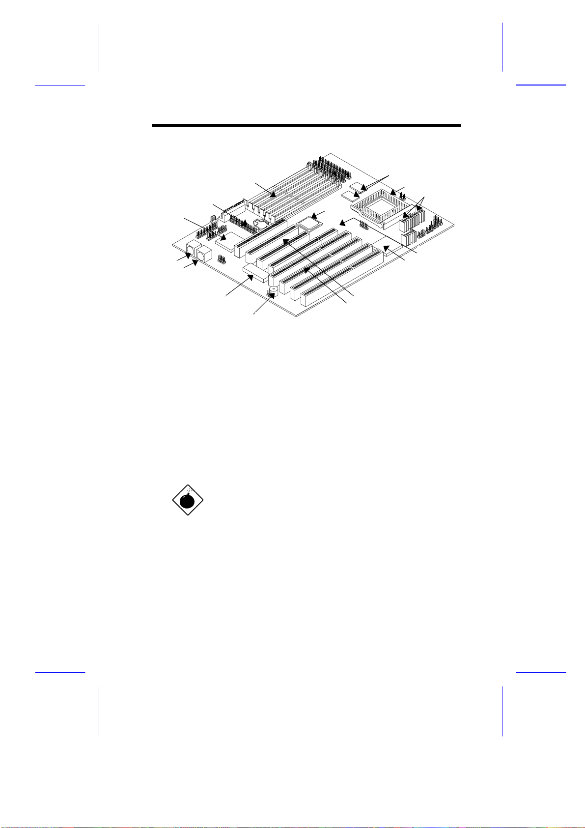
1
2
3
4
5
6
7
15
14
13
12
1 Super I/O controller 11 ISA slots
2 Battery 12 Buzzer
3 SIMM sockets 13 Flash ROM
4 Pipelined-burst cache 14 PS/2 mouse connector
5 CPU socket 15 PS/2 keyboard connector
6 Voltage regulators with heatsink
7 Host-to-PCI bridge
8 SCSI/ASM card slot
9 PCI-ISA bridge
10 PCI slots
10
11
8
9
Figure 1-1 System Board Layout
The heatsink becomes very hot when the
system is on. NEVER touch the heatsink with
any metal or with your hands.
System Board 1-3
Page 4

1.2 ESD Precautions
Electrostatic discharge (ESD) can damage your processor, disk
drives, expansion boards, and other components. Always observe
the following precautions before you install a system component.
1. Do not remov e a component f rom it s protectiv e packagi ng until
you are ready to i nstall it.
2. Wear a wrist grounding strap and attach i t to a met al part of the
system unit bef ore handling com ponents. If a wrist strap is not
avai lable, mai ntain contact with the system unit throughout any
procedure requiring ESD protection.
1.3 Pre-installation Instructions
Always observe the following before you install a system component :
1. Turn off the system power and all the per ipherals connected to
the unit before opening it.
2. Open the system according to the instructions in the housing
install ation manual.
3. Follow the ESD precautions in section 1.2 before handling a
system component.
4. Remov e any expansion boards or peripher als that block access
to the SIMM sockets or CPU socket.
5. See the following sections for specific instructions on the
component you wish to install.
Do not attempt t he procedures described in
the following sections unless you are a
qualified service tec hnic ian.
1-4 User’s Guide
Page 5
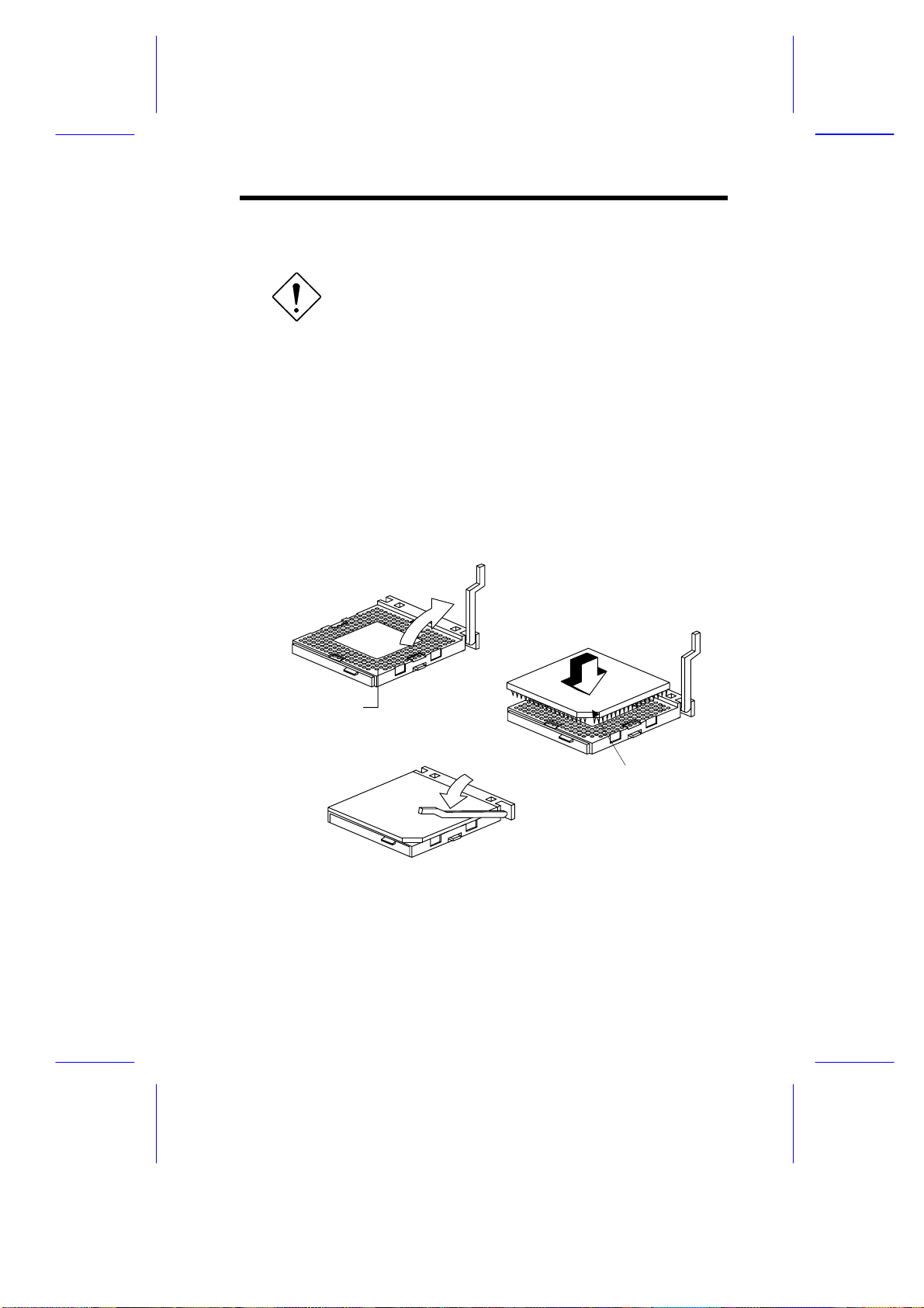
1.4 Installing a CPU
Observe the ESD precautions when
installing components. See section 1. 2.
The system board features a zero-insertion force (ZIF) socket for
easy CPU install ation.
Follow these steps to install a CPU:
1. Pull up t he socket lever.
2. Insert the CPU, m aking sure that pin 1 (indi cated by a notched
corner) of the CPU connects to hol e 1 of the socket.
3. Pull down the socket lev er to lock the CP U into the socket.
Step 1
Step 2
Hole for Pin 1
Step 3
Notched corner
Figure 1-2 Installing a CPU
System Board 1-5
Page 6

See section 1.9 for the post-installation
instructions.
1.5 Upgrading the CPU
Follow these steps to upgrade the CP U:
1. Turn off the system power.
2. Pull up t he socket lever.
3. Remove the installed CPU.
4. Install t he upgrade CPU. Ref er t o secti on 1.4 on how to i nstall a
CPU.
1-6 User’s Guide
Page 7
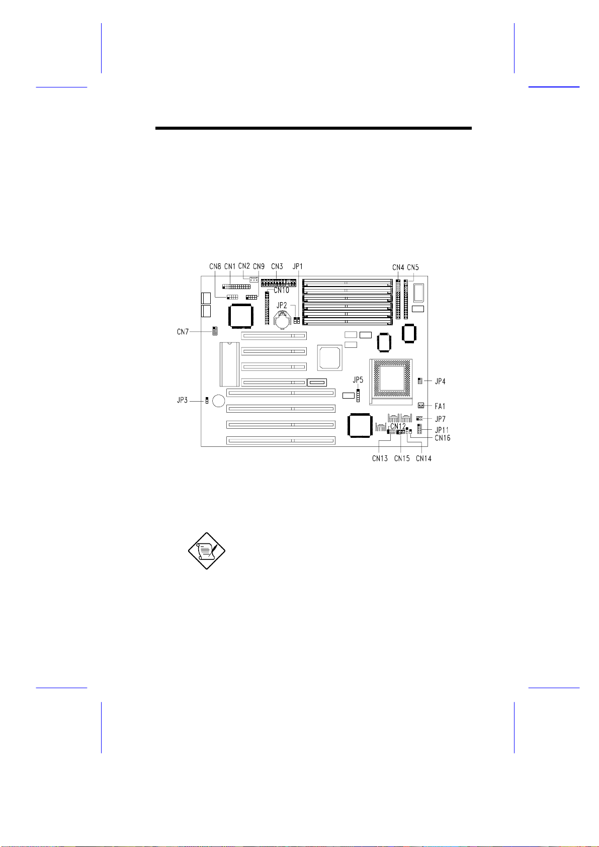
1.6 Jumpers and Connectors
1.6.1 Jumper and Connector Locations
Figure 1-3 shows the jum per and connector l ocations on t he system
board.
Figure 1-3 Jumper and Connect or Loc ations
The blackened pin of a jumper or a connector
represents pin 1.
System Board 1-7
Page 8

1.6.2 Jumper Settings
Table 1-1 lists the system board jumpers with their corresponding
settings and func tions.
Table 1-1 Jumper Settings
Jumper Setting Function
BIOS Type
JP1
Password Check
JP2 1-2
Buzzer/Speaker
JP3 1-2
Core/Bus Ratio
JP4 1-2, 3-4
CPU Frequency
JP5 2-3, 4-5
CPU Type
JP7
*
1-2
2-3
*
2-3
*
2-3
1-2
OPEN
3-4
1-2, 3-4
1-2, 4-5
1-3, 2-4
3-5, 4-6
3-5, 4-6
3-5, 4-6
Acer BIOS
OEM BIOS
Check password
Bypass password
Buzzer
External speakers
P54C/K5 P55C/K6
5/2 5/2
2/1 2/1
3/2 7/2
3/1 3/1
66 MHz
60 MHz
50 MHz
P54C, K5
K6-233
K6-166, 200
P55C
JP11
1-2, 3-4, 5-6, 7- 8
5-6, 7-8
1-2, 7-8
7-8
P54C, K5
K6-233
K6-166, 200
P55C
*
Default
1-8 User’s Guide
Page 9

1.6.3 Connector Functions
Table 1-2 l ists the dif f erent c onnectors on the system board and their
respective func tions.
Table 1-2 Connector Funct ions
Connector Function
CN1 Printer connector
CN2 Software shut-down power supply control connector
CN3 Power connector
CN4 IDE1 connector
CN5 IDE2 connector
CN7 Universal serial bus interface
CN8 COM2 connector
CN9 COM1 connector
CN10 Diskette drive connector
CN11 Power LED, reset, keylock connector
CN12 HDD LED connector
CN13 Speaker connector
CN14 Turbo LED connector
CN15 LED board connector
CN16 SMM switch
FA1 CPU fan connector
System Board 1-9
Page 10

1.6.4 USB Interface (optional)
The system board may come wit h an onboard USB connector and a
separate bracket connector. T he USB interface enabl es the system
to support more per ipherals.
To install a USB bracket c onnec tor, sim ply do the following:
1. Locate the USB connec tor on the system board. See Figure 1- 3.
2. Attach the USB bracket connector onto the onboard USB
connector. Notice t hat one pin of the USB brac ket connector is
covered. This is to ensure proper connection (refer to the
following figure).
Figure 1-4 Installing a USB Br ac k et Connector
1-10 User’s Guide
Page 11

1.7 Installing Memory
The system memory is expandable to 192 MB by adding si ngle i n-l i ne
memory modules (SIMMs). See Figure 1-1 for the location of the
SIMM sockets. Section 1.7.1 tells how to install SIMMs.
The six 72-pin S IMM sockets on board accept singl e-density (4- and
16-MB) and double-density (8- and 32-MB) SIMMs, with 70-ns or 60ns DRAM speed. These SIMMs may support either EDO or FPM
DRAM types, with or without ECC/Parit y funct ion. The ECC f uncti on
allows the system to automatically correct one-bit errors and detect
multiple-bit errors. Table 1-3 lists the possible memory
configurations.
Table 1-3 Memory Configurat ions
Bank 0 Bank 1 Bank 2 Total
Slot 1 Slot 2 Slot 3 Slot 4 Slot 5 Slot 6 Memory
4 MB 4 MB 8 MB
4 MB 4 MB 4 MB 4 MB 16 MB
4 MB 4 MB 4 MB 4 MB 4 MB 4 MB 24 MB
8 MB 8 MB 16 MB
8 MB 8 MB 4 MB 4 MB 24 MB
8 MB 8 MB 4 MB 4 MB 4 MB 4 MB 32 MB
8 MB 8 MB 8 MB 8 MB 32 MB
8 MB 8 MB 8 MB 8 MB 4 MB 4 MB 40 MB
8 MB 8 MB 8 MB 8 MB 8 MB 8 MB 48 MB
16 MB 16 MB 32 MB
16 MB 16 MB 4 MB 4 MB 40 MB
16 MB 16 MB 4 MB 4 MB 4 MB 4 MB 48 MB
16 MB 16 MB 8 MB 8 MB 48 MB
16 MB 16 MB 8 MB 8 MB 4 MB 4 MB 56 MB
16 MB 16 MB 8 MB 8 MB 8 MB 8 MB 64 MB
16 MB 16 MB 16 MB 16 MB 64 MB
System Board 1-11
Page 12

Table 1-3 Memory Configurat ions ( c ontinued)
Bank 0 Bank 1 Bank 2 Total
Slot 1 Slot 2 Slot 3 Slot 4 Slot 5 Slot 6 Memory
16 MB 16 MB 16 MB 16 MB 4 MB 4 MB 72 MB
16 MB 16 MB 16 MB 16 MB 8 MB 8 MB 80 MB
16 MB 16 MB 16 MB 16 MB 16 MB 16 MB 96 MB
32 MB 32 MB 64 MB
32 MB 32 MB 4 MB 4 MB 72 MB
32 MB 32 MB 4 MB 4 MB 4 MB 4 MB 80 MB
32 MB 32 MB 8 MB 8 MB 80 MB
32 MB 32 MB 8 MB 8 MB 4 MB 4 MB 88 MB
32 MB 32 MB 8 MB 8 MB 8 MB 8 MB 96 MB
32 MB 32 MB 16 MB 16 MB 96 MB
32 MB 32 MB 16 MB 16 MB 4 MB 4 MB 104 MB
32 MB 32 MB 16 MB 16 MB 8 MB 8 MB 112 MB
32 MB 32 MB 16 MB 16 MB 16 MB 16 MB 128 MB
32 MB 32 MB 32 MB 32 MB 128 MB
32 MB 32 MB 32 MB 32 MB 4 MB 4 MB 136 MB
32 MB 32 MB 32 MB 32 MB 8 MB 8 MB 144 MB
32 MB 32 MB 32 MB 32 MB 16 MB 16 MB 160 MB
32 MB 32 MB 32 MB 32 MB 32 MB 32 MB 192 MB
1-12 User’s Guide
Page 13

1.7.1 Installing a SIMM
Observe the ESD precautions when installing
components. See s ec tion 1.2.
Follow these steps to install a SIM M :
1. Careful ly slip a SIMM at a 45° angle into a socket m aking sure
that the curv ed edge indicati ng the pin 1 of t he SIMM m atches
pin 1 of the socket.
A SIMM fits only in one direction. If you slip
in a SIMM but would not completely fit, you
may have inserted it the wrong way.
Reverse the orientation of the SIMM.
2. Gently push the S IMM to a v er tic al posi tion until t he pegs of t he
socket slip into t he hol es on the SIM M, and t he hol ding c li ps loc k
the SIMM into position. The SIMM should be at a 90° angle
when installed.
1
Pin 1 Indicator
(curved edge)
Figure 1-5 Installing a SIMM
System Board 1-13
2
Peg
Hole
Page 14

See section 1.9 for the post-installation
instructions.
1.7.2 Removing a SIMM
Follow these steps to remove a S IMM:
1. Press the holding clips on both sides of the SIMM outward to
release it.
2. Move the SIMM to a 45° angle.
3. Pull t he S IMM out of the socket.
Holding Clip
1
3
2
Figure 1-6 Removing a SIMM
1.7.3 Reconfiguring the System
The system automatically detects the amount of memory installed.
Run Setup to v iew the new v alue f or t otal system mem ory and mak e
a note of it.
1-14 User’s Guide
Page 15

1.8 SCSI/ASM Card (optional)
1.8.1 Features and Layout
The system board may come with or without a Small Computer
System Interface/Advanced Server Management (SCSI/ASM) card.
This card integrates the Adaptec AIC-7880 SCSI controller and an
optional ASM module.
The SCSI/ASM card offers the following functions:
•
CPU thermal detection
•
5V and 3.3V voltage det ec tion
•
PCI bus utilization calculation
Figure 1-6 shows the card layout.
1 68-pin Wide SCSI connector 6 FAN3 connector
2 SCSI controller 7 FAN2 connector
3 Jumper JP1 8 ASM chip (optional)
4 50-pin Narrow SCSI connector 9 Jumper JP2
5 FAN1 connector
Figure 1-7 SCSI/ASM Card Layout
*
Housing fan connector
System Board 1-15
*
10 Narrow SCSI outlet connector
*
*
Page 16

1.8.2 Jumper Settings
Table 1-4 li sts the SCSI/ASM card j umpers with thei r corresponding
settings and func tions.
Table 1-4 SCSI/ASM Card Jumper Settings
Jumper Setting Function
JP1 1-2
2-3
JP2 1-2
2-3
Terminator ON
Terminator by 7880 chip
For M3A
Reserved
1.8.3 Installing the SCSI/ASM Card
Observe the ESD precautions when installing
components. See s ec tion 1.2.
Follow these steps to install the SCSI/ASM card:
1. Remove the card from its protective pac k aging.
2. Locate the PCI/ISA-shared slot on the system board (see Figure
1-1).
3. Align the golden fingers of the SCSI/ASM card t o t he sl ot.
1-16 User’s Guide
Page 17

4. Gently but firmly insert the card. Make sure that the board is
properly seated.
Figure 1-8 Installing the SCSI/ASM Card
See section 1.9 for the post-installation
instructions.
System Board 1-17
Page 18

1.9 Post-installation Instructions
Observe the following procedures after installing a system
component:
1. See to it t hat t he com ponent s are instal l ed accordi ng t o the stepby-step instruct ions in their r espect iv e sect ions.
2. Make sure you have set all the required jumpers. See secti on
1.6.2 f or the correct jumper settings.
3. Replace any ex pansion boards or peripherals that you remov ed
earlier.
4. Replace the system c over.
5. Connect the necessary cables and tur n on the system.
1.10 Error Messages
In the event that y ou recei ve an error m essage, do not cont i nue using
the computer. Note the message and take corrective action
immediately. This section describes the different types of error
messages and suggests corrective measures.
There are two general t y pes of error m essages:
•
Software
•
System
1.10.1 Software Error Messages
Software error messages are returned by your operating system or
application. These messages typically appear after you boot the
operating system or when you run your appl ications. If you receiv e
this type of message, consult your application or operating system
manual for help.
1-18 User’s Guide
Page 19

1.10.2 System Error Messages
A system error message indicates a problem with the c omputer itself .
These messages normally appear during the power-on self-test,
before the operating system prompt appears. Table 1-5 lists the
system error messages in alphabetical order.
Table 1-5 System Error Messages
Error Message Corrective Action
Bad CMOS Battery Replace battery. Contact your dealer.
CMOS Checksum Error Run Setup.
Diskette Drive
Controller Error
Diskette Drive Error Diskette may be bad. If not, check the
DRAM Configuration
Error
Equipment
Configuration Er r or
Hard Disk Co n troller
Error
Hard Disk 0 Error Check all cable connections. Check the
Hard Disk 1 Error Check all cable connections. Check the
Hard Disk 0 Extended
Type Error
Hard Disk 1 Extended
Type Error
I/O Parit y Er r or Contact your dealer.
Keyboard Error or No
Keyboard Connected
Keyboard Interface
Error
Check and connect the cable to the
diskette drive or controller.
diskette drive and replace if necessary.
Check and modify DRAM configuration
to agree with Table 1-3.
Run Setup.
Check and connect the cable to the hard
disk drive or controller.
hard disk and replace if necessary.
hard disk and replace if necessary.
Run Setup.
Run Setup.
Check and connect the keyboard to the
system unit.
Contact your dealer.
System Board 1-19
Page 20

Table 1-5 System Error Messages (continued)
Error Message Corrective Action
Keyboard Locked Unlock the keyboard.
Memory Error Check SIMMs on the system board.
Contact your dealer.
Memory Size Mismatch Run Setup.
Serial 1 Conflict Run Setup.
Disable Onboard Serial 1.
Serial 2 Conflict Run Setup.
Disable Onboard Serial 2.
Parallel Port Confl i c t Run Setup.
Disable Onboard Parallel Port .
Pointing Device Error Check or connect the pointing device.
Contact your dealer.
Pointing Device Interface
Error
Press F1 key to continue
or Ctrl-Alt-Esc for Setup
Press F1 to Setup or
other key to continue
Press Esc to turn off NMI,
any key to reboot
Protected Mode Test Fail Contact your dealer.
RAM BIOS Error Contact your dealer.
Real Time Clock Error Run Setup.
Shadow RAM Fail Contact your dealer.
Sys tem Memor y Address
Error
Contact your dealer.
Press
Press
Press
Press any key to reboot the system.
Check SIMMs on system boar d or
contact your dealer.
or
and reconfigure the system.
to disregard NMI error.
.
1-20 User’s Guide
Page 21

1.10.3 Correcting Error Conditions
As a general rule, the "Press F1 to conti nue" error m essage is caused
by a configuration problem which can be easily corrected. An
equipment malf unction is more li kely to cause a fatal error, i.e., an
error that causes com plete system fail ur e.
Here are some corrective measures for er r or c onditions:
1. Run Setup. You m ust know the correct configur ation v alues for
your system before you enter Setup, which is why you should
write these val ues down when the system is correct l y conf i gured.
An incorrect Setup configuration is a major cause of power-on
error messages, especially for a new system.
2. Remove the system cover according to the directions in the
system housing instal lation gui de. Check that the system boar d
and any expansion boards are set corr ec tly.
3. If you cannot access a new disk, it m ay be because your disk is
not physically formatted. Physically format the disk using the
FDISK and FORMAT commands.
4. Check that all connectors and boards are secure. Consult the
system housing installati on guide for assistance.
If you follow the corrective steps above and still receive an error
message, the cause may be an equipment malfunction.
If you are sure that your configuration values are correct and your
battery is in good condition, the problem may lie in a damaged or
defectiv e c hip. Contact an authorized service center for assistance.
System Board 1-21
 Loading...