

Page 1

AcerPower
4400
User’s Guide
Page 2

Copyright 1999 Acer Incorporated
All Rights Reserved. Printed in Taiwan
Changes may be made periodically to the information in this publication without obligation
t o n ot if y an y pe r so n o f s u ch r ev is io n or c ha ng es . Su c h c h an g es wi ll b e i n co rp or a te d i n n e w
editions of this manu al or supplementary documents an d publications. This company makes
no representations or warranties, either expressed or implied, with respect to the contents
hereof and specifically disclaims the implied warranties of merchantability or fitness for a
particular purpose.
Record the model number, serial number, purchase da te, and place of purchase information
in the space provid ed below. The serial number and model number are recorded on the label
affixed to your computer . All correspondense concerning your unit should include the ser ial
number, model number, and purchase information.
No part of this publication may be reproduced, stored in a retrieval system, or transmitted,
in any form or by any means, electronic, mechanical, photocopy, recording, or otherwise,
without the prior written permission of Acer Incorporated.
All trademarks, registered trademarks and/or service marks are the
properties of their respective owners.
Page 3

Notices
FCC Notice
This device has been tested and found to comply with the limits for a Class B
digital device pursuant to Part 15 of the FCC Rules. These limits are designed
to provide reasonable protection against harmful interference in a residential
installation. This dev ice generates, uses, and c an radiate radio frequency ene rgy
and, if not installed and used in accordance with the instructions, may cause
harmful interference to radio communications.
However, there is no guarantee that interference will not occur in a particular
installation. If this device does cause harm ful interference to radi o or television
reception, which c an be determined by turning the dev ice off and on, the user is
encouraged to try to correct the interference by one or more of the following
measures:
Reorient or relocate the receiving antenna
❑
Increase the separation between the device and receiver
❑
Connect the device into an outlet on a circuit different from that to
❑
which the receiver is connected
Consult the dealer or an experienced radio/television techn ician for help
❑
iii
Notice: Shield Cables
All connections to o ther computing devices must be made using shielded cables
to maintain compliance with FCC regulations.
Notice: Peripheral Devices
Only peripherals (input/output devices, terminals, printers, etc.) certified to
comply with the Class B limits may be attached to this equipment. Operation
with non certified peripherals is likely to result in interference to radio and TV
reception.
Caution
Changes or modifications not expressly approved by the manufacturer could
void the user’s authority, which is granted by the Federal Communications
Commission, to operate this computer.
Page 4

Notices
iv
Use Conditions
This part complies with Part 15 of the FCC Rules. Operation is subject to
the following two conditions: (1) this device may not cause harmful
interference, and (2) this device must accept any interference received,
including interference that may cause undesired operation.
Notice: Canadian Users
This Class B digital apparatus meets all requirements of the Canadian
Interference-Causing Equipment Regulations.
Remarque à l’intention des utilisateurs canadiens
Cet appareil numérique de la classe B respected toutes les exigences du
Règlement sur le matériel brouilleur du Canada.
Important Safety Instructions
Read these instructions carefully. Save these instructions for future
reference.
Follow all warnings and instructions marked on the product.
1.
Unplug this product from the wall outlet before cleaning. Do not
2.
use liquid cleaners or aerosol cleaners. Use a damp cloth for
cleaning.
Do not use this product near water.
3.
Do not place this product on an unstable cart, stand, or table. The
4.
product may fall, causing serious damage to the product.
Slots and openings in the cabinet and the back or bottom are
5.
provided for ventilation; to ensure reliable operation of t he product
and to protect it from overheating, these openings must not be
blocked or covered. The openings should never be blocked by
placing the product on a bed, sofa, rug, or other similar surface.
This product should never be placed near or over a radiator or heat
register, or in a built-in installation unless proper ventilation is
provided.
This product should be operated from the type of power indicated
6.
on the marking label. If you are not sure of the type of power
available, consult your dealer or local power company.
Do not allow anything to rest on the power cord. Do not locate
7.
this product where persons will walk on the cord.
If an exte nsion cord is used w ith this product, make sure that the
8.
total ampere rating of the equipment plugged into the extension
Page 5

cord does not exceed the extens ion cord ampere rating. Also, make
sure that the total rating of all products plugged into the wall outlet
does not exceed the fuse rating.
Never push objects of any kind into this product through cabinet
9.
slots as they may touch dangerous voltage points or short out parts
that could result in a fire or electric shock. Never spill liquid of any
kind on the product.
Do not attempt to service this product yourself, as opening or
10.
removing covers may expose you to dangerous voltage points or
other risks. Refer all servicing to qualified service personnel.
Unplug this product from the wall outlet and refer servicing to
11.
qualified service personnel under the following conditions:
When the power cord or plug is damaged or frayed
a.
If liquid has been spilled into the product
b.
If the product has been exposed to rain or water
c.
If the product does not operate normally when the operating
d.
instructions are followed. Adjust only those controls that are
covered by the operating instructions since improper
adjustment of other controls may result in damage and will
often require extensive work by a qualified technician to
restore the product to normal condition.
If the product has been dropped or the cabinet has been
e.
damaged
If the product exhibits a distinct change in performance,
f.
indicating a need for service.
Replace the battery with the same type as the product's battery we
12.
recommend. Use of another battery may present a risk of fire or
explosion. Refer battery replacement to a qualified serviceman.
Warning! Battery may explode if not handled properly. Do not
13.
recharge, disassemble or dispose of in fire. Keep away from
children and dispose of used batteries promptly.
Use only the proper type of power supply cord set (provided in
14.
your keyboard/manual accessories box) for this unit. It should
be a detachable type: UL listed/CSA certified, type SVT/SJT,
rated 6A 125V minimum, VDE approved or its equivalent.
Maximum length is 15 feet (4.6 meters).
v
Page 6

Notices
vi
Year 2000 Compliance Statement
The AcerPower 4400 carries the "Hardware NSTL Tested Year 2000
Compliant" logo, which certifies that this model has been tested by
NSTL using the YMark2000 test, and has been found to meet NSTL's
standards for Year 2000 hardware compliance.
For more details, check the Acer Year 2000 Resource Center at http://
www.acer.com.tw/service/y2k/
Laser Compliance Statement
The CD-ROM drive in this computer is a laser product. The CDROM drive’s classification label (shown below) is located on the
drive.
CLASS 1 LASER PRODUCT
CAUTION:
AVOID EXPOSURE TO BEAM.
APPAREIL A LASER DE CLASSE 1 PRODUIT
LASERATTENTION:
INVISIBLE EN CAS D’OUVERTURE. EVITTER TOUTE
EXPOSITION AUX RAYONS.
LUOKAN 1 LASERLAITE LASER KLASSE 1
VORSICHT:
ABDECKUNG GEÖFFNET NICHT DEM STRAHLL AUSSETZEN
PRODUCTO LÁSER DE LA CLASE I
ADVERTENCIA:
ABIERTO. EVITE EXPONERSE A LOS RAYOS.
ADVARSEL:
STRÅLEN.
INVISIBLE LASER RADIATION WHEN OPEN.
RADIATION DU FAISCEAU LASER
UNSICHTBARE LASERSTRAHLUNG, WENN
RADIACIÓN LÁSER INVISIBLE AL SER
LASERSTRÅLING VEDÅBNING SE IKKE IND I
Page 7

VARO! LAVATTAESSA OLET ALTTINA LASERSÅTEILYLLE.
VARNING:
ÅLÅ TUIJOTA SÅTEESEENSTIRRA EJ IN I STRÅLEN
VARNING:
ÖPPNADSTIRRA EJ IN I STRÅLEN
ADVARSEL:
STRÅLEN
LASERSTRÅLNING NÅR DENNA DEL ÅR ÖPPNAD
LASERSTRÅLNING NAR DENNA DEL ÅR
LASERSTRÅLING NAR DEKSEL ÅPNESSTIRR IKKE INN I
vii
Page 8

viii
Notices
Page 9

Table of Contents
Notices . . . . . . . . . . . . . . . . . . . . . . . . . . . . . . . . . . . . . . . . . . . . . . . iii
Chapter 1 Getting Started . . . . . . . . . . . . . . . . . . . . . . . . . . . . . . 1
Overview . . . . . . . . . . . . . . . . . . . . . . . . . . . . . . . . . . . . . . . . . . . . . . . . . . 3
Preinstallation . . . . . . . . . . . . . . . . . . . . . . . . . . . . . . . . . . . . . . . . . . . . . . 4
Selecting a Site . . . . . . . . . . . . . . . . . . . . . . . . . . . . . . . . . . . . . . . . . . 4
Unpacking Components. . . . . . . . . . . . . . . . . . . . . . . . . . . . . . . . . . . . 4
Features . . . . . . . . . . . . . . . . . . . . . . . . . . . . . . . . . . . . . . . . . . . . . . . . . . . 5
Front Panel. . . . . . . . . . . . . . . . . . . . . . . . . . . . . . . . . . . . . . . . . . . . . . 5
Rear Panel . . . . . . . . . . . . . . . . . . . . . . . . . . . . . . . . . . . . . . . . . . . . . . 6
Internal Components . . . . . . . . . . . . . . . . . . . . . . . . . . . . . . . . . . . . . 7
Connecting System Components . . . . . . . . . . . . . . . . . . . . . . . . . . . . . . . . 8
Connecting the Keyboard. . . . . . . . . . . . . . . . . . . . . . . . . . . . . . . . . . . 8
Connecting the Monitor . . . . . . . . . . . . . . . . . . . . . . . . . . . . . . . . . . . . 9
Connecting the Mouse . . . . . . . . . . . . . . . . . . . . . . . . . . . . . . . . . . . . . 9
Connecting the Printer (optional). . . . . . . . . . . . . . . . . . . . . . . . . . . . 10
Connecting Multimedia Components. . . . . . . . . . . . . . . . . . . . . . . . . 11
Connecting to the Network (optional) . . . . . . . . . . . . . . . . . . . . . . . . 12
Connecting USB Devices (optional). . . . . . . . . . . . . . . . . . . . . . . . . . 13
Turning On Your Computer . . . . . . . . . . . . . . . . . . . . . . . . . . . . . . . . . . . 14
Turning Off Your Computer . . . . . . . . . . . . . . . . . . . . . . . . . . . . . . . . . . . 15
Troubleshooting. . . . . . . . . . . . . . . . . . . . . . . . . . . . . . . . . . . . . . . . . . . . 16
Error Messages . . . . . . . . . . . . . . . . . . . . . . . . . . . . . . . . . . . . . . . . . . . . 18
Software Error Messages. . . . . . . . . . . . . . . . . . . . . . . . . . . . . . . . . . 18
System Error Messages . . . . . . . . . . . . . . . . . . . . . . . . . . . . . . . . . . . 18
Correcting Error Conditions . . . . . . . . . . . . . . . . . . . . . . . . . . . . . . . . 20
ix
Chapter 2 System Board Information. . . . . . . . . . . . . . . . . . . . . . 23
Features . . . . . . . . . . . . . . . . . . . . . . . . . . . . . . . . . . . . . . . . . . . . . . . . . . 25
Board Layout . . . . . . . . . . . . . . . . . . . . . . . . . . . . . . . . . . . . . . . . . . . . . . 26
Jumpers and Connectors . . . . . . . . . . . . . . . . . . . . . . . . . . . . . . . . . . . . . 27
Panel Connector. . . . . . . . . . . . . . . . . . . . . . . . . . . . . . . . . . . . . . . . . 27
Jumper Setting . . . . . . . . . . . . . . . . . . . . . . . . . . . . . . . . . . . . . . . . 28
Connector Description . . . . . . . . . . . . . . . . . . . . . . . . . . . . . . . . . . . 28
Hard Disk Support . . . . . . . . . . . . . . . . . . . . . . . . . . . . . . . . . . . . . . . . . . 30
Audio Function. . . . . . . . . . . . . . . . . . . . . . . . . . . . . . . . . . . . . . . . . . . . . 31
USB Support . . . . . . . . . . . . . . . . . . . . . . . . . . . . . . . . . . . . . . . . . . . . . . 32
Hardware Monitoring Function. . . . . . . . . . . . . . . . . . . . . . . . . . . . . . . . . 33
Wake-on Modem Function . . . . . . . . . . . . . . . . . . . . . . . . . . . . . . . . . . . . 34
Page 10

Table of Contents
x
Wake-on LAN Function. . . . . . . . . . . . . . . . . . . . . . . . . . . . . . . . . . . . . . . 35
Chapter 3 Award BIOS . . . . . . . . . . . . . . . . . . . . . . . . . . . . . . . . 37
Entering Setup . . . . . . . . . . . . . . . . . . . . . . . . . . . . . . . . . . . . . . . . . . . . . 40
Standard CMOS Setup . . . . . . . . . . . . . . . . . . . . . . . . . . . . . . . . . . . . . . . 41
BIOS Features Setup . . . . . . . . . . . . . . . . . . . . . . . . . . . . . . . . . . . . . . . . 44
Chipset Features Setup. . . . . . . . . . . . . . . . . . . . . . . . . . . . . . . . . . . . . . . 49
DRAM Clock Table . . . . . . . . . . . . . . . . . . . . . . . . . . . . . . . . . . . . . . 51
Power Management Setup . . . . . . . . . . . . . . . . . . . . . . . . . . . . . . . . . . . . 53
Power Management Mode Table . . . . . . . . . . . . . . . . . . . . . . . . . . . . 57
PnP/PCI Configuration . . . . . . . . . . . . . . . . . . . . . . . . . . . . . . . . . . . . . . . 58
Load Setup Defaults . . . . . . . . . . . . . . . . . . . . . . . . . . . . . . . . . . . . . . . . . 61
Product Information. . . . . . . . . . . . . . . . . . . . . . . . . . . . . . . . . . . . . . . . . 62
Integrated Peripherals . . . . . . . . . . . . . . . . . . . . . . . . . . . . . . . . . . . . . . . 63
Password Setting. . . . . . . . . . . . . . . . . . . . . . . . . . . . . . . . . . . . . . . . . . . 67
IDE HDD Auto Detection. . . . . . . . . . . . . . . . . . . . . . . . . . . . . . . . . . . . . . 68
Save & Exit Setup. . . . . . . . . . . . . . . . . . . . . . . . . . . . . . . . . . . . . . . . . . . 69
Exit without Saving. . . . . . . . . . . . . . . . . . . . . . . . . . . . . . . . . . . . . . . . . . 70
Chapter 4 Upgrading the System . . . . . . . . . . . . . . . . . . . . . . . . 71
Installation Precautions . . . . . . . . . . . . . . . . . . . . . . . . . . . . . . . . . . . . . . 73
ESD Precautions . . . . . . . . . . . . . . . . . . . . . . . . . . . . . . . . . . . . . . . . 73
Preinstallation Instructions . . . . . . . . . . . . . . . . . . . . . . . . . . . . . . . . 73
Postinstallation Instructions . . . . . . . . . . . . . . . . . . . . . . . . . . . . . . . 74
Opening the System. . . . . . . . . . . . . . . . . . . . . . . . . . . . . . . . . . . . . . . . . 75
Removing the Housing Cover . . . . . . . . . . . . . . . . . . . . . . . . . . . . . . 75
Replacing the Housing Cover. . . . . . . . . . . . . . . . . . . . . . . . . . . . . . . 78
Installing Additional Memory . . . . . . . . . . . . . . . . . . . . . . . . . . . . . . . . . . 79
Installing a DIMM . . . . . . . . . . . . . . . . . . . . . . . . . . . . . . . . . . . . . . . 80
Removing a DIMM. . . . . . . . . . . . . . . . . . . . . . . . . . . . . . . . . . . . . . . 81
Reconfiguring the System . . . . . . . . . . . . . . . . . . . . . . . . . . . . . . . . . 81
Upgrading the CPU. . . . . . . . . . . . . . . . . . . . . . . . . . . . . . . . . . . . . . . . . . 82
Removing the CPU. . . . . . . . . . . . . . . . . . . . . . . . . . . . . . . . . . . . . . . 82
Installing the CPU . . . . . . . . . . . . . . . . . . . . . . . . . . . . . . . . . . . . . . . 84
Replacing the Hard Disk. . . . . . . . . . . . . . . . . . . . . . . . . . . . . . . . . . . . . . 86
Installing PCI or AGP Expansion Card . . . . . . . . . . . . . . . . . . . . . . . . . . . 89
Page 11

Getting Started
Chapter 1
Page 12

This chapter gives you a general introduction to the system unit and
tells you how to select a site and set up the system. It also includes a
simple troubleshooting section to help you to check your system
before you ask for technical support.
Page 13

Overview
The AcerPower 4400 is an all-in-one, high-performance system
that supports the Intel Pentium III CPU. It utilizes the PCI
(Peripheral Component Interface) and the AGP (Accelerated
Graphics Port) bus designs. Both designs improve system
performance, enabling the system to support various
multimedia functions and applications. In addition, the system
board supports a jumper-less design that automatically detects
the CPU voltage and frequency.
Aside from the standard I/O (Input/Output) interfaces such as
two serial ports, one parallel port, and PS/2 keyboard and
mouse ports, the system also comes with two USB (Universal
Serial Bus) ports, one mono Microphone-in port, one stereo
Line-in port, one Line-out port, and one Game/MIDI (Musical
Instrument Digital Interface) port. These additional ports are
included to enable the system to accommodate additional
peripherals.
The system may also come with an onboard audio controller, a
fax/modem card and/or a network card. These additional
features offer special functions that will enable you to take full
advantage of the system. Special features such as hardware
monitoring, USB, power management, video and audio
functions are discussed in this manual.
3
Furthermore, this system is fully compatible with MS-DOS
v6.X, SCO UNIX, Windows 95/98 and Windows NT operating
systems.
If you made some changes in the CMOS settings (BIOS) and your system
fails to boot, do the following:
1. Hold down the HOME key while you reboot your system.
2. When the system boots up, enter Setup by pressing
BIOS Setup main menu appears.
3. Choose Load Setup Defaults to undo the changes you made and set
the BIOS setup parameters to their original settings.
Ctrl-Alt-Esc. The
Page 14

Chapter 1
4
Getting Started
Preinstallation
The preinstallation process involves the following activities:
❑
❑
Selecting a Site
Consider the following when selecting a site for your
computer:
❑
❑
❑
Selecting a site
Unpacking components
Determine the best site for your system. Cable paths
should not run near equipment that might cause
electromagnetic or radio frequency interference such as
radio transmitters, televisions, copy machines, or heating
and air-conditioning equipment.
Route cables away from personnel and equipment traffic.
Avoid dusty areas and extremes of temperature and
humidity.
Unpacking Components
Unpack the contents of each box carefully. Save all packing
materials in case you need to move or ship the system in the
future.
Check that all items are present and in good condition.
Contact your dealer immediately if anything is missing or
damaged.
Page 15
Features
The basic configuration consists of a system unit, a keyboard, a
CD-ROM drive, a diskette drive, a fixed disk drive and a
mouse.
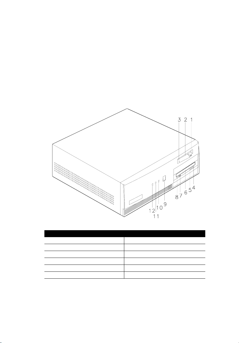
Front Panel
The figure below shows the system unit front panel.
5
No. Component No. Component
1 3.5-inch diskette drive eject button 7 Volume Control
2 3.5-inch diskette drive 8 Headphone/Earphone port
3 3.5-inch diskette drive LED 9 Power button
4 Stop/Eject button 10 Power/Suspend LED
5 Play/Forward button 11 Turbo LED
6 CD-ROM tray 12 Hard Disk/Message LED
Page 16
Chapter 1
6
Getting Started
Rear Panel
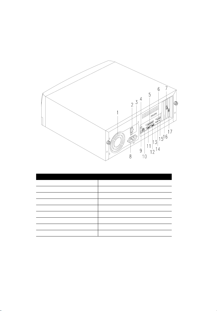
The figure below shows the system unit rear panel.
No. Component No. Component
1 Fan 10 USB ports
2 System main power switch 11 Serial port 1
3 Voltage selector 12 Serial port 2
4 PS/2 keyboard port 13 Speaker-out/Audio-out port
5 Parallel port 14 Audio-in port
6 Game/MIDI port 15 Microphone-in port
7 VGA/Monitor port 16 Add-on card brackets
8 System power socket 17 LAN (Local Area Network) port
9 PS/2 mouse port
Page 17
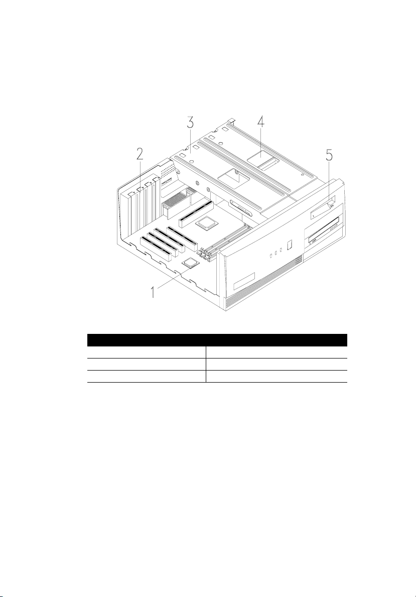
Internal Components
The figure below shows the system unit internal components.
7
No. Component No. Component
1 System board 4 Hard disk
2 Expansion card brackets 5 Floppy disk drive
3 Disk drive metal brackets
Page 18
Chapter 1
8
Getting Started
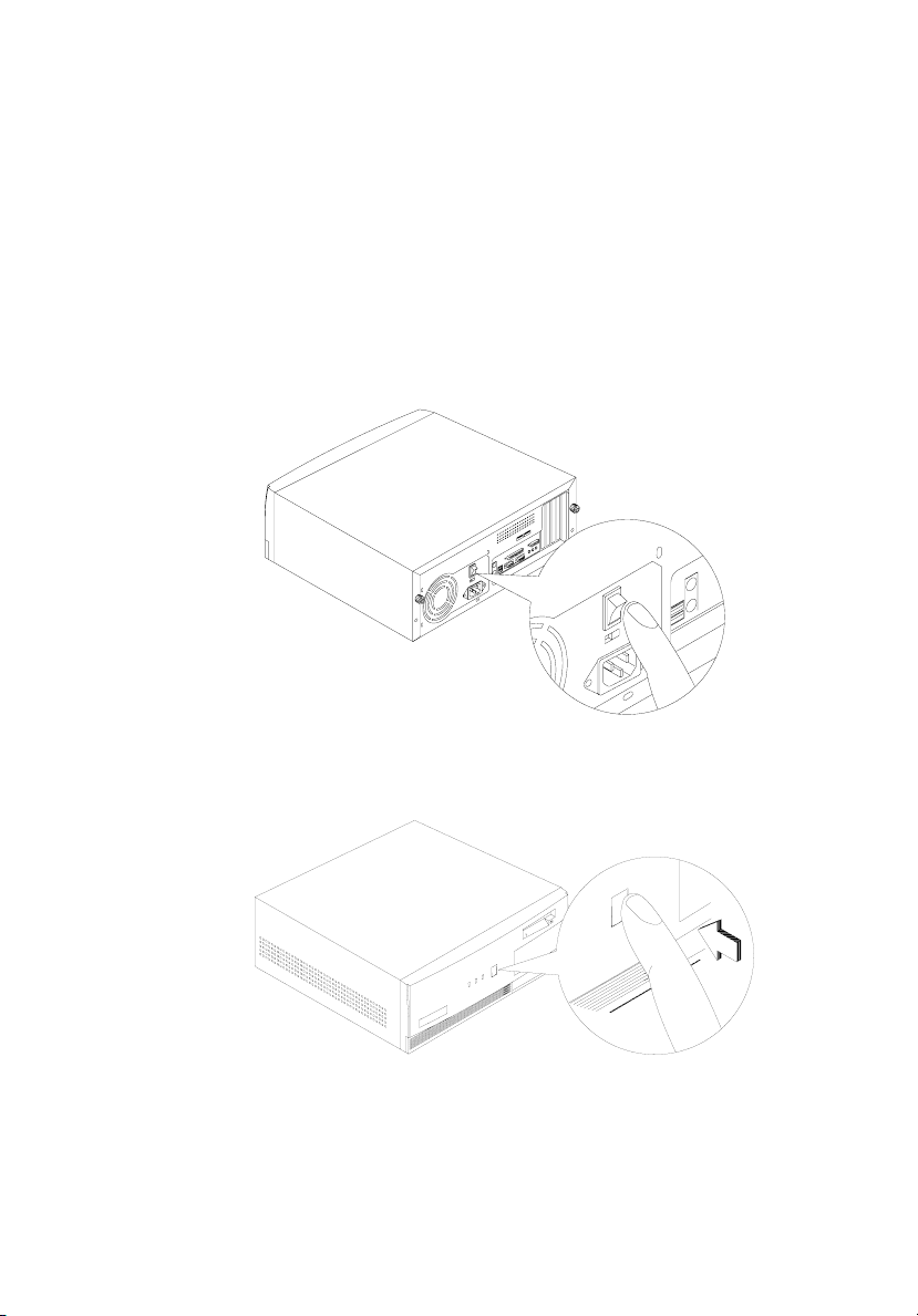
Connecting System Components
Caution: Do not turn on the system main power switch on the rear panel of
the system or plug the system in until you finish connecting all system
components.
The following sections show how to connect each component
to the system:
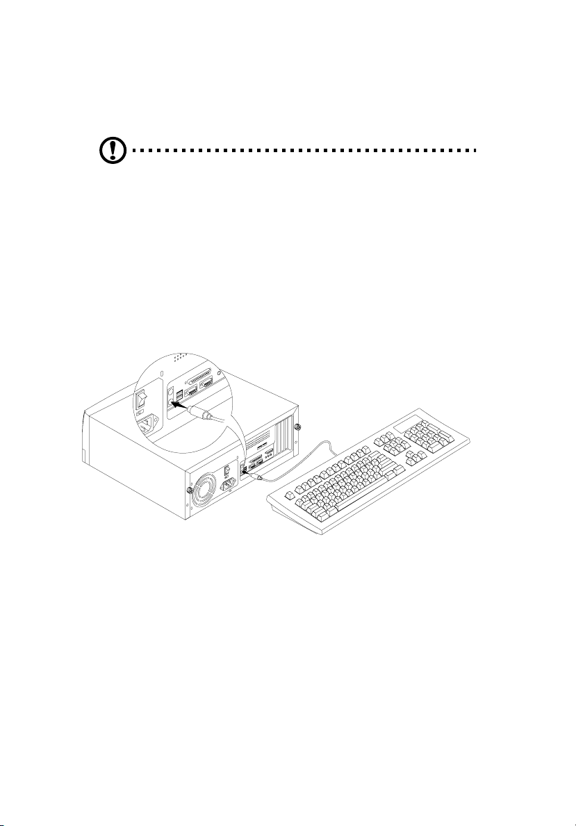
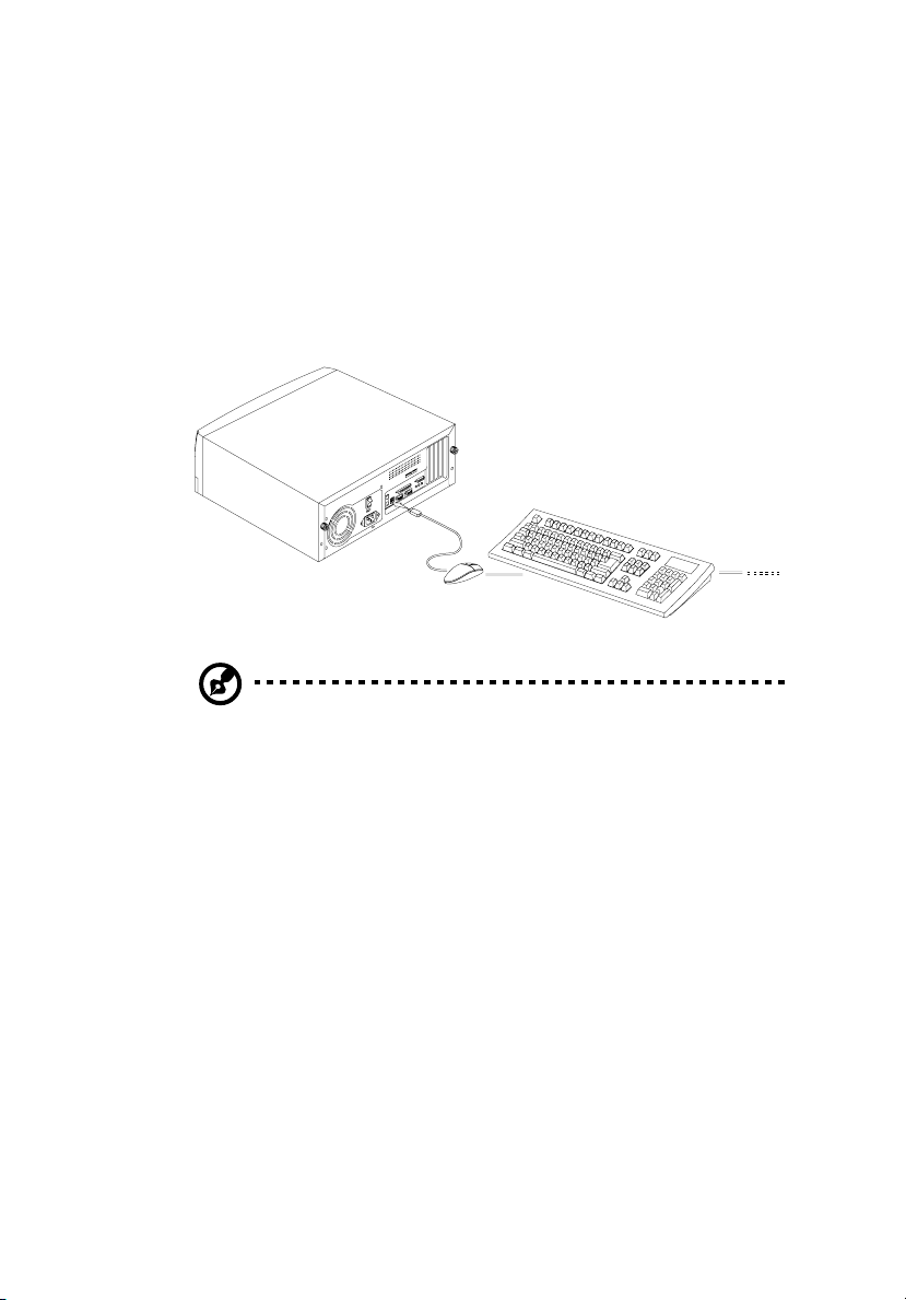
Connecting the Keyboard
Plug the keyboard cable into the keyboard socket on the rear
panel.
Page 19
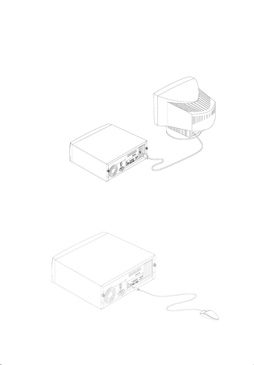
Connecting the Monitor
Plug the monitor signal cable into the VGA connector on the
rear panel.
Connecting the Mouse
9
Plug the mouse cable into the mouse connector on the rear
panel.
Page 20
Chapter 1
10
Getting Started
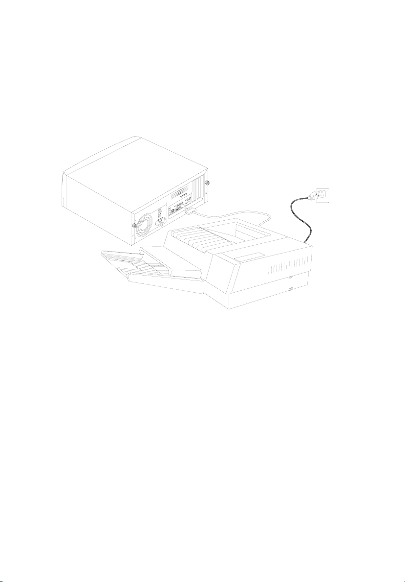
Connecting the Printer (optional)
Check your printer before you connect it to your system. If
you have a parallel printer, connect it to the parallel port on
the rear panel.
If you have a serial printer or other serial peripheral, connect it
to the serial port (COM2). See “Rear Panel” on page 6 for the
location of the serial ports.
Page 21
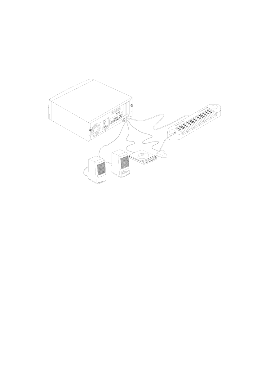
Connecting Multimedia Components
Your system also supports optional multimedia features.
Connect the multimedia components as shown below:
11
Page 22
Chapter 1
12
Getting Started
Connecting to the Network (optional)
Your system may come with a LAN (Local Area Network) card
for network connection. To connect your system to the
network, plug the network cable into the card’s network port.
Page 23
Connecting USB Devices (optional)
The USB ports on the rear panel enable the system to support
additional serial devices without using up your system
resources.
To connect a USB device, simply plug the device cable into a
USB port on the rear panel.
Note: Most USB devices have a built-in USB port which allows you to
daisy-chain other devices.
13
Page 24
Chapter 1
14
Getting Started
Turning On Your Computer
After you have connected all peripherals and cables, follow
these steps to turn on your computer:
1.
Turn on all peripherals connected to the system such as
the monitor, printer, fax, speakers, etc.
2.
Locate the system main power switch on the back of the
system and turn it on.
3.
Press the power button located on the front of the system
unit..
When the system finishes booting, the computer is ready for
use.
Page 25

Turning Off Your Computer
1.
Turn off all peripherals connected to the system such as
the monitor, printer, fax, speakers, etc.
2.
Press the power button located on the front of the system
unit for at least four seconds. Quickly pressing the
button may put the system in the Suspend mode only.
Note: You do not need to turn off the system main power switch on the rear
panel every time you turn off your computer.
Turn off the system main power switch only if:
- you will not use your system for a long period of time.
- you need to open your system for any purpose, such as troubleshooting
or upgrading.
If the system main power switch is not available, you must unplug the
system.
15
Page 26

Chapter 1
16
Getting Started
Troubleshooting
If you encounter a hardware problem, we recommend that you
review the following suggestions before calling for service:
General failure
❑
❑
❑
❑
❑
Front panel light doesn’t work
❑
Are all cables securely plugged?
Are all system components and peripherals turned on?
Is the system main power switch on?
Is the power outlet burned out? You may check this by
plugging in and turning on some other piece of
equipment.
Are any cables damaged? Are they properly routed and
coiled? Entwined cables may cause signal interference.
After turning off the computer, check inside the system
unit and make sure that the front panel LED connector
for the LED that is not working is correctly plugged.
Refer to “Jumpers and Connectors” on page 27 to identify
the proper LED connector.
“Garbage” or nothing appears on the screen
❑
Is the monitor turned on? Is the screen brightness
adjusted properly?
Warning! Never open the monitor case. The CRT monitor retains very high
voltage levels even after the power is turned off. Refer all monitor service to
qualified service technicians.
Keyboard is dead
❑
Is the keyboard cable plugged in? Turn off the system
and plug in the keyboard.
Caution: Do not plug or unplug the keyboard while the power is on.
Page 27

Printer doesn’t work
❑
Is the printer power turned off?
❑
Is the printer cable connected to the correct port (serial
or parallel)?
❑
Are your application and the printer configured for the
same operating values? Be sure there is no conflict with
any port on an add-on card. For details, check the
documentation that came with your printer.
❑
Is the printer out of paper or jammed? Check the
printer’s status indicator lights.
❑
Are the printer cables tangled? To prevent signal
interference, neatly fold or coil excess cable length.
Add-on card fails intermittently
❑
Do two add-on cards have conflicting addresses? “PnP/
PCI Configuration” on page 58 shows where you can see
the addresses in the BIOS Setup screen.
If you receive an error message
❑
Read the corrective actions listed in “Error Messages” on
page 18.
17
Page 28

Chapter 1
18
Getting Started
Error Messages
In the event that you receive an error message, do not
continue using the computer. Note the message and take
corrective action immediately. This section describes the
different types of error messages and suggests corrective
measures.
There are two general types of error messages:
❑
Software
❑
System
Software Error Messages
Software error messages are returned by your operating system
or application. These messages typically appear after you boot
the operating system or when you run your applications. If
you receive this type of message, consult your application or
operating system manual for help.
System Error Messages
A system error message indicates a problem with the computer
itself. These messages normally appear during the power-on
self-test, before the operating system prompt appears.
The table below lists the system error messages.
Error Message Corrective Action
BIOS ROM checksum error Bios ROM failed. Contact your dealer
CMOS battery failed CMOS battery is out of power. Please
or an authorized service center.
change the system battery. For the
location of the system battery, refer to
page 26 or contact your dealer or an
authorized service center.
Page 29

Error Message Corrective Action
19
CMOS Checksum Error Defaults loaded
Conflict I/O Ports Conflict in I/O resource settings
DISK BOOT FAILURE, INSERT
SYSTEM DISK AND PRESS
ENTER
Floppy disk(s) fail ( ) No floppy disk detected. Set the Halt
Keyboard error or no keyboard
present
Memory test fail System detects memory error during
CMOS checksum error during post
process. Press "F1" to ignore it or
press
Ctrl-Alt-Esc
setup utility.
detected. Contact your dealer or an
authorized service center.
There is no bootable floppy disk and
hard disks detected. Please insert a
bootable floppy disk into floppy drive.
On parameter (see page 41) to either
one of the settings except “All Errors”
and “All, but keyboard”. When the
system encounters this error, it will not
show this message.
No Keyboard detected. Set the Halt On
parameter (see page 41) to either one
of the settings except “All Errors” and
“All, but diskette”. When the system
encounters this error, it wil not show
this message.
POST. Replace the SDRAM DIMMs or
contact your dealer or an authorized
service center.
to enter cmos
Primary IDE channel no 80
conductor cable installed
Primary master hard disk fail Primary master hard disk type
System displays this message when
you are using a UDMA66 hard disk
with a 40 pins conductor cable.
mismatch between user's setting in
STANDARD CMOS SETUP (see page
41) and what BIOS detected during
POST.
Page 30

Chapter 1
20
Getting Started
Error Message Corrective Action
Primary slave hard disk fail Primary slave hard disk type mismatch
Secondary IDE channel no 80
conductor cable installed
Secondary master hard disk
fail
Secondary slave hard disk fail Secondary master hard disk type
Correcting Error Conditions
As a general rule, the "Press F1 to continue" error message is
caused by a configuration problem which can be easily
corrected. An equipment malfunction is more likely to cause a
fatal error, i.e., an error that causes complete system failure.
between user's setting in STANDARD
CMOS SETUP (see page 41) and what
BIOS detected during POST.
System displays this message when
you are using a UDMA66 hard disk
with a 40 pins conductor cable.
Secondary master hard disk type
mismatch between user's setting in
STANDARD CMOS SETUP (see page
41) and what BIOS detected during
POST.
mismatch between user's setting in
STANDARD CMOS SETUP (see page
41) and what BIOS detected during
POST.
Here are some corrective measures for error conditions:
1.
Remove the system cover according to the directions in
the system housing installation guide. Check that the
system board and any expansion boards are set correctly.
2.
Check that all connectors and boards are secure. Consult
the system housing installation guide for assistance.
If you have purchased a new hard disk drive and your
computer cannot detect it or access it after installing it, it may
be because your disk is not physically formatted. Physically
format the disk using the FDISK and FORMAT commands.
Page 31

Caution: These commands are performed in DOS. We recommend that
you familiarize yourself with the DOS commands first before you format
your hard disk.
If you follow the corrective steps above and still receive an
error message, the cause may be an equipment malfunction.
If you are sure that your configuration values are correct and
your battery is in good condition, the problem may lie in a
damaged or defective chip. Contact an authorized service
center for assistance.
Note: If you do not know how to contact an authorized service center, call
your distributor.
21
Page 32

Chapter 1
22
Getting Started
Page 33

System Board Information
Chapter 2
Page 34

This system board is uniquely-designed to support not only the
common features found in today’s high-performance system boards,
but the multimedia functions as well.
This chapter gives a detailed discussion of the board’s components
and features.
Page 35

Features
This high-performance system board comes with the following
features:
❑
❑
❑
❑
❑
❑
❑
❑
❑
❑
❑
❑
❑
❑
❑
Intel Pentium III processor with 512-KB second-level
cache running at 450, 500, 533, 550, or 600 MHz
Three 168-pin DIMM sockets that accept 32-, 64-, and
128-MB PC-100 (100 MHz) and PC-133 (133 MHz)
SDRAM (Synchronous DRAM); allows 384-MB maximum
system memory
Award Plug-n-Play, 2Mbit flash ROM BIOS
Enhanced PCI local bus IDE controller
Onboard Audio CODEC chipset AD1881
Two PCI enhanced IDE interfaces that support up to four
IDE devices
External ports
❑
PS/2 keyboard and mouse ports
❑
Two buffered high-speed serial ports
❑
One parallel port that supports Standard Parallel Port
(SPP)/Extended Capabilities Port (ECP)/Enhanced
Parallel Port (EPP) modes
❑
Two Universal Serial Bus (USB) ports
Three PCI (Peripheral Component Interconnect) slots
One AGP (Accelerated Graphic Port) slot
Plug-and-Play
Software Shutdown support for Windows 95/98
Power Management
Hardware Monitoring function
Wake-on Modem function
Wake-on LAN function
25
Page 36

Chapter 2
26
System Board Information
Board Layout
Your system board should look just like the following figure:
The following table lists the components that you will find on
the system board:
No. Component No. Component
1 PS/2 mouse port 13 AD1881 audio chipset
2 PS/2 keyboard port 14 Buzzer
3 USB ports 15 VIA VT82C686A chipset
4 Serial port 1 16 Award BIOS chipset
5 Parallel port 17 Battery
6 Serial port 2 18 IDE 2 connector
7 MIDI/Game port 19 IDE 1 connector
8 Speaker-out/Audio-out port 20 Floppy disk drive connector
9 Audio-in port 21 ATX power supply connector
10 Microphone-in port 22 DIMM sockets (three sockets)
11 AGP slot 23 VIA VT82C694X system controller
12 PCI slots (three slots) 24 CPU socket
Page 37

Jumpers and Connectors
Refer to the following figure for the location of the jumpers
and connectors on the system board:
27
Panel Connector
PWLED1 is a power LED connector for Aspire 6400 and AcerPower 4400.
However, PWRLED in the PANEL, as shown below, is the one for AcerPower
8400.
Page 38

Chapter 2
28
System Board Information
Jumper Setting
Jumper Function and Settings
JP12
1-2
2-3
JP14
1-2
2-3
JP27
1-2
2-3
Sound
Enabled (default)
Disabled
CMOS Setting
Normal operation (default)
Clear CMOS
PC Beep Output
Onboard buzzer (default)
Line-out
Connector Description
Connector Description
PWR2 ATX power connector
USB2 USB connector
FDC Floppy drive connector
IDE1 IDE1 primary channel
IDE2 IDE2 secondary channel
CPUFAN1 3-pin CPU fan connector
CPUFAN2 2-pin CPU fan connector
CPUTHER 2-pin CPU Thermal detector connector
FAN1 Fan connector (reserved)
PANEL Front panel (Multifunction) connector
CD-IN 1 and 2 CD-audio connector (Do not use both connectors at
the same time)
Page 39

Connector Description
INSPK Internal speaker connector (reserved)
MODEM-CN Mono-in (Pin 1-2) and Mic-out (Pin 3-4)
BZ1 Onboard Buzzer
WOM Wake-on-Modem connector (reserved)
WOL Wake-on-LAN connector
SMB SMBus connector
IA Intrusion Alarm connector
AOL Alert-on-LAN connector
29
SPWR
*
Power switch connector
* Located in the PANEL connector.
Page 40

Chapter 2
30
System Board Information
Hard Disk Support
The board comes with an enhanced PCI IDE controller that
supports PIO mode 4 and Ultra DMA (Direct Memory Access)
mode data transfers. Two PCI IDE interfaces are mounted on
the board to enable the system to support a maximum of four
IDE hard disks, or any other IDE devices. See “Jumpers and
Connectors” on page 27 for the location of the IDE interfaces.
Connect the cables according to the IDE hard disk
configuration listed in the table below. Follow the instructions
in the housing installation manual on how to install a hard disk
in the system.
IDE Connector Master Slave
IDE 1 Hard disk 0 Hard disk 1
IDE 2 Hard disk 2/IDE CD-ROM Hard disk 3
Page 41

Audio Function
For its audio solution, the board comes with a PCI-based audio
controller and the following ports:
❑
Mono microphone port
❑
Stereo line-in port
❑
Stereo line-out port
❑
Game/MIDI port
These connectors enable the system to accommodate external
audio devices. For instructions on how to connect the external
audio devices, see “Connecting Multimedia Components” on
page 11.
31
Page 42

Chapter 2
32
System Board Information
USB Support
USB is a new serial bus design that is capable of cascading low
and medium-speed peripherals (less than 12 Mbps) such as a
keyboard, mouse, joystick, scanner, printer and modem/ISDN.
With USB, complex cable connections at the back panel of
your PC can be eliminated.
The board comes with two USB ports. See “Board Layout” on
page 26 for the location of the ports.
Page 43

Hardware Monitoring Function
The Hardware Monitoring function allows you to check the
system resources, either locally or in a computer network, by
using software such as Acer ADM (Advanced Desktop
Manager). Acer ADM is a desktop management program that
offers SMART (System Monitoring Analysis and Reporting
Technology) for checking local or network connected systems.
In addition, it also enables the PC hardware and applications to
be OS (operating system) independent.
To enable the Hardware Monitoring function, you need to
install Acer ADM. Contact your dealer for information on the
availability of the software. Refer to the software
documentation for more details on the Hardware Monitoring
function.
33
Page 44

Chapter 2
34
System Board Information
Wake-on Modem Function
The Wake-on Modem function enables the system to resume
from shutdown or suspend mode by monitoring the fax/
modem (or any device of similar type) activities. Any signal or
activity detected from the Modem Ring-in connector
automatically returns the system to normal operation.
Page 45

Wake-on LAN Function
This system board implements a WOL connector. To use the
LAN Wake-up function, you need to install a network card that
supports this feature. In addition, you also need to install a
network management software such as ADM (Advanced
Desktop Manager). This feature allows the system to be
activated via network access. Common network functions
such as remote access, file sharing, etc. are also supported.
Refer to “Jumpers and Connectors” on page 27 for the location
of the WOL connector on the system board.
35
Page 46

Chapter 2
36
System Board Information
Page 47

Award BIOS
Chapter 3
Page 48

This chapter contains detailed discussion about the Award BIOS
utility. You will need this information for reconfiguring your system
or for resetting your system back to its original settings in case you
have reconfigured it improperly.
Page 49

The Award BIOS utility is a hardware configuration program
built into your system’s Basic Input/Output System (BIOS). It
supports a jumper-less design that automatically detects the
CPU voltage and frequency.
If you made some changes in the CMOS settings (BIOS) and
your system fails to boot, do the following:
1.
Hold down the
system.
2.
When the system boots up, enter Setup by pressing
Alt-Esc
. The BIOS Setup main menu appears.
3.
Choose
made and set the BIOS setup parameters to their original
settings.
Load Setup Defaults
HOME
key while you reboot your
to undo the changes you
Ctrl-
39
Page 50

Chapter 3
40
Award BIOS
Entering Setup
To enter Setup, press
self-test). The “BIOS Setup” main menu then appears:
Note: Choose “Load Setup Defaults” for best performance with light
system loading. Refer to “Load Setup Defaults” on page 61.
The section at the bottom of the screen tells how to control the
screen. Use the
exit, and
the bottom of the screen displays a brief description of the
highlighted item. After selecting an item, press
it or enter a submenu.
F10
to save the changes and exit. Another section at
Ctrl-Alt-Esc
arrow keys
during the POST (Power-on
to move between items,
Enter
ESC
to
to select
The parameters on the screens show default values. These
values may not be the same as those in your system.
The grayed items on the screens have fixed settings and are
not user-configurable.
Page 51

Standard CMOS Setup
The Standard CMOS Setup sets the basic system parameters
such as the date, time, and the hard disk type. Use the arrow
keys to highlight an item and
value for each item.
PgUp
or
PgDn
41
to select the
The table below describes each Standard CMOS Setup
parameter. Settings in
boldface
are the default and suggested
settings.
Parameter
Date Lets you set the date following
Time Lets you set the time following
Description Format/Options
the weekday-month-day-year
format.
the hour-minute-second
format.
Weekday: Sun, Mon,
Tue, Wed, Thu, Fri, Sat
Month: Jan, Feb...Dec
Day: 1 to 31
Year: 1980 to 2079
Hour: 0 to 23
Minute: 0 to 59
Second: 0 to 59
Page 52

42
Chapter 3
Award BIOS
Parameter
Hard Disk Type
Primary Master
Primary Slave
Secondary Master
Secondary Slave
Hard Disk Mode
Primary Master
Primary Slave
Secondary Master
Secondary Slave
Description Format/Options
This item lets you select the
IDE hard disk parameters that
your system supports. Auto
enables BIOS to automatically
detect the parameters of
installed HDD during the
POST (Power-on self-test). If
you prefer to enter HDD
parameters manually, select
User. Select None if no HDD
is connected to the system.
The IDE CD-ROM is always
automatically detected.
This enhanced IDE feature
allows the system to use a
hard disk with a capacity of
more than 528MB. This is
made possible through
Logical Block Address (LBA)
mode translation. LBA is now
considered a standard feature
of current IDE hard disks on
the market because of its
capability to support
capacities larger than 528MB.
Note that if your HDD is
formatted with LBA On, it will
not be able to boot with LBA
Off.
Auto
User
None
Auto
Normal
LBA
Large
Drive A Allows you to configure your
floppy drive A.
1.44 MB, 3.5-inch
None
360 KB, 5.25-inch
1.2 MB, 5.25-inch
720 KB, 3.5-inch
2.88 MB, 3.5-inch
Page 53

43
Parameter
Drive B Allows you to configure your
Floppy 3 Mode
Support
Video This item specifies the type of
Halt On This parameter enables you to
Description Format/Options
floppy drive B.
Allows your floppy drive(s) to
run in 3 modes including 2.88
MB mode.
video card in use. The default
setting is VGA/EGA. Since
current PCs use VGA only, this
function is almost useless and
may be disregarded in the
future.
control the system stops in
case of Power-on self-test
(POST) errors.
None
360 KB, 5.25-inch
1.2 MB, 5.25-inch
720 KB, 3.5-inch
1.44 MB, 3.5-inch
2.88 MB, 3.5-inch
Both
Drive A
Drive B
Disabled
EGA/VGA
CGA40
CGA80
Mono
All Errors
No Errors
All, But Keyboard
All, But Diskette
All, But Disk/Key
Page 54

Chapter 3
44
Award BIOS
BIOS Features Setup
The table below describes the parameters found in this menu.
Settings in
boldface
are the default and suggested settings.
Parameter
CPU Internal Cache Enabling this parameter
CPU L2 Cache ECC
Checking
Quick Power-On Self
Te st
Description Format/Options
activates the CPU internal
cache. Disabling the
parameter slows down the
system.
This item lets you enable or
disable the L2 Cache ECC
checking.
This parameter speeds up
POST by skipping some items
that are normally checked.
Enabled
Disabled
Disabled
Enabled
Enabled
Disabled
Page 55

45
Parameter
Boot Sequence This parameter allows you to
Silent Boot This item is used to decide if
Display
Configuration Data
Swap Floppy Drive This item allows you to swap
Description Format/Options
specify the system boot up
search sequence. The hard
disk IDs are listed below:
C: Primary master
D: Primary slave
E: Secondary master
F: Secondary slave
LS: LS120
Zip: IOMEGA ZIP Drive
the Aspire logo displays when
the system boots up.
This item is used to decide if
the configuration table
displays when the system
boots up.
floppy drives. For example, if
you have two floppy drives (A
and B), you can assign the
first drive as drive B and the
second drive as drive A or
vice-versa.
C,A,CDROM
A,C,SCSI
C,A,SCSI
C,CDROM,A
CDROM,C,A
CDROM,A,C
D,A,SCSI
E,A,SCSI
SCSI,A,C
SCSI,C,A
C only
LS/ZIP,C
Enabled
Disabled
Enabled
Disabled
Disabled
Enabled
Boot Up Floppy Seek When enabled, the BIOS
issues the seek command to
the floppy drive during POST
to move the floppy drive head
forward and backward.
Enabled
Disabled
Page 56

46
Chapter 3
Award BIOS
Parameter
Boot Up NumLock
Status
Gate A20 Option The settings for this
Memory Parity/ECC
Check
Typematic Rate
Setting
Typematic Rate
(Chars/Sec)
Description Format/Options
Setting this parameter to On
enables the numeric function
of the numeric keypad. Set
this parameter to Off to
disregard the function.
Disabling the numeric function
allows you to use the numeric
keypad for cursor control.
parameter are Normal and
Fast. If the data transfer is
controlled by the 8042 chip,
set the parameter to Normal.
The Fast setting transfers the
control to ASICs.
This item is used to enable or
disable the parity/ECC check
function.
When enabled, continually
holding down a key on the
keyboard will generate
repeatedly keystrokes.
This item allows you to
control the speed of repeated
keystrokes.
On
Off
Fast
Normal
Disabled
Enabled
Disabled
Enabled
6, 8, 10, 12, 15, 20,
24, and 30
Typematic Delay
(Msec)
This parameter allows you to
control the delay time (in
millisaeconds) between the
first and the second keystroke
(where the repeated
keystrokes begin).
250, 500, 750, and
1000
Page 57

47
Parameter
Security Option The System option limits
PCI/VGA Palette
Snoop
Description Format/Options
access to both the System
boot and BIOS setup. A
prompt asking you to enter
your password appears on the
screen every time you boot
the system.
The Setup option limits
access only to BIOS setup.
To disable the security option,
select Password Setting from
the main menu, don't type
anything and just press Enter.
Enabling this item informs the
PCI VGA card to keep silent
(and to prevent conflict) when
the palette register is updated
(i.e., accepts data without
responding to any
communication signals). This
is useful only when two
display cards use the same
palette address and are
plugged into the PCI bus at
the same time (such as MPEQ
or Video capture). In such
case, the PCI VGA is silent
while the MPEQ/Video capture
is set to function normally.
System
Setup
Disabled
Enabled
OS Select for DRAM
> 64MB
Video BIOS Shadow VGA BIOS Shadowing means
Set to OS/2 if your system is
utilizing an OS/2 operating
system and has a memory
size of more than 64 MB.
to copy video display card
BIOS into the DRAM area.
This enhances system
performance because DRAM
access time is faster than
ROM.
Non-OS/2
OS/2
Enabled
Disabled
Page 58

48
Chapter 3
Award BIOS
Parameter
C800-CBFF Shadow
CC00-CFFF Shadow
D000-D3FF Shadow
D400-D7FF Shadow
D800-DBFF Shadow
DC00-DFFF Shadow
Description Format/Options
These six items are for
shadowing ROM code on
other expansion cards. Before
you set these parameters, you
need to know the specific
addresses of that ROM code.
If you do not know this
information, enable all the
ROM shadow settings.
Disabled
Enabled
Page 59

Chipset Features Setup
Caution: Make sure you fully understand the items contained in this menu
before you try to change anything. You may change the parameter settings
to improve system performance. However, changing these parameters
could make your system unstable if the setting is not correct for your
system configuration.
49
The table below describes the parameters found in this menu.
Settings in
boldface
are the default and suggested settings.
Parameter Description Options
Bank 0/1 DRAM Timing
Bank 2/3 DRAM Timing
Bank 4/5 DRAM Timing
SDRAM Cycle Length 3
These items are used to set DRAM
timing parameters which can be
automatically set by BIOS.
SDRAM 10ns
SDRAM 8ns
Normal
Medium
Fast
Tu rb o
2
Page 60

50
Chapter 3
Award BIOS
Parameter Description Options
DRAM Clock Please refer to the table on page 51
to set the DRAM clock.
Memory Hole This option lets you reserve system
Fast R-W Turn Around Lets you configure the hard disk
System BIOS
Cacheable
Video RAM Cacheable This item lets you cache Video RAM
AGP Mode If you are not sure which AGP mode
memory area for special ISA cards.
The chipset accesses code/data of
these areas from the ISA bus
directly. Normally, these areas are
reserved for memory mapped I/O
cards.
drive connected to the slave port of
IDE channel 2.
Enabling this item allows you to
cache the system BIOS to further
enhance system performance.
A000 and B000.
to choose, simply select the highest
AGP mode (4x) available. The
system automatically downgrades
to the proper mode.
CPU CLK
CPU CLK +33
CPU CLK -33
Disabled
Enabled
Enabled
Disabled
Disabled
Enabled
Disabled
Enabled
4x
1x
2x
AGP Aperture Size
(MB)
CPU Micro Codes The micro codes are used to fix
This item lets you determine the
effective size of the AGP Graphic
Aperture.
bugs of the Pentium III CPU; we
strongly recommend that you
enable this item for system
reliability reasons. However, these
micro codes may slightly reduce
CPU performance. We provide this
option for your convenience if you
would like to test it.
64, 4, 8, 16,
32, and 128
Enabled
Disabled
Page 61

Parameter Description Options
51
Clock Spread Spectrum This item is used to set the clock
spread spectrum for EMI testing.
Normally, you don’t need to change
the default setting.
CPU Speed Detected This motherboard can detect the
CPU speed automatically and shows
it in on this entry.
CPU Clock Frequency This item lets you set the external
clock (bus clock). The correct
setting may vary depending on your
particular CPU. Refer to your CPU
specifications for more details.
CPU Clock Ratio The Intel Pentium III is designed to
have a different Internal (Core) and
External (Bus) frequency. This item
lets you select the ratio of Core/Bus
frequency.
Setup CPU Speed The CPU Speed is derived from the
product of "CPU Clock Frequency"
and "CPU Clock Ratio".
NOTE: The value in the Setup CPU Speed parameter may differ from the
value in the CPU Speed Detected parameter. However, the actual running
CPU speed shown is always the value in the CPU Speed Detected parameter.
On
Off
66.8 MHz
100 MHz
133 MHz
1.5, 2.0, 2.5,
3.0, 3.5, 4.0,
4.5, 5.0, 5.5,
6.0, 6.5, 7.0,
7.5, and 8.0
DRAM Clock Table
CPU SDRAM Recommended Setting
133 MHz PC133 CPU CLK
133 MHz PC100 CPU CLK-33M
100 MHz PC133 CPU CLK+33M
Page 62

52
Chapter 3
Award BIOS
CPU SDRAM Recommended Setting
100 MHz PC100 CPU CLK
Page 63

Power Management Setup
The table below describes the parameters found in this menu.
Settings in
Parameter Description Options
boldface
are the default and suggested settings.
53
Power
Management
PM Control by
APM
This function allows you to set the
default parameters for power-saving
modes. Set it to Disable to turn off
the power management function. Set
it to User Define to choose your own
parameters. See the Power
Management Mode Table on page 57.
If "Max Saving" in the Power
Management parameter is selected,
you can turn on this item, transfer
power management control to APM
(Advanced Power Management) and
enhance the power saving function.
For example, you can stop the CPU
internal clock.
User Define
Max Saving
Mix Saving
Disabled
Yes
No
Page 64

54
Chapter 3
Award BIOS
Parameter Description Options
Video Off After Turns off the video monitor after the
selected power down option.
Video Off
Method
MODEM Use
IRQ
Soft-Off by
PWRBTN
This determines the way that the
monitor stays off. Blank Screen
writes blanks to the video buffer. V/H
SYNC+Blank allows BIOS to control
VSYNC and HSYNC signals. This
function applies only for DPMS
(Display Power Management
Standard) monitor. The DPMS mode
uses the DPMS function provided by
the VGA card.
This item lets you set an IRQ for the
modem.
This is a specification of ACPI and
supported by hardware. When Delay
4 sec. is selected, the soft power
switch on the front panel can be used
to control power On, Suspend and
Off. If the switch is pressed less than
4 sec during power On, the system
will go into Suspend mode. If the
switch is pressed longer than 4 sec,
the system will be turned Off. The
other setting is Instant-Off, where the
soft power switch is only used to
control On and Off, there is no need
to press 4 sec, and there is no
Suspend.
Suspend
N/A
Doze
Standby
V/H SYNC + Blank
DPMS
Blank Screen
3, 4, 5, 7, 9, 10,
11, and N/A
Delay 4 sec.
Instant-Off
HDD Power
Down
This option lets you specify the IDE
HDD idle time before the device
enters the power down state. This
item is independent from the power
states previously described in this
section (Standby and Suspend).
Disabled
1 min.
15 min.
Page 65

Parameter Description Options
55
Doze Mode This item lets you set the period of
time after which the system enters
into Doze mode. The system activity
(or event) is detected by monitoring
the IRQ signals or other events (such
as I/O).
Suspend Mode This item lets you set the period of
VGA
PCI/Master
time after which the system enters
into Suspend mode. The Suspend
mode can be Power On Suspend or
Suspend to Hard Drive, and it is
selected in the "Suspend Mode
Option".
To enable or disable the detection of
COM port, LPT, VGA , and PCI
activities for power down state
transition.
Disabled
1 min.
2 min.
4 min.
8 min.
12 min.
20 min.
30 min.
40 min.
1 Hour
Disabled
1 min.
2 min.
4 min.
8 min.
12 min.
20 min.
30 min.
40 min.
1 Hour
OFF
ON
HDD & FDD To enable or disable the detection of
HDD and FDD activities for power
down state transition.
LPT & COM To enable or disable the detection of
COM port and LPT activities for
power down state transition.
ON
OFF
LPT/COM
None
LPT
COM
Page 66

56
Chapter 3
Award BIOS
Parameter Description Options
Wake on LAN/
Modem
Primary INTR This item is used to enable or disable
IRQ [3-7,12-14] Select Primary or Disabled option to
IRQ [8,15] Select Primary or Disabled option to
This option allows you to enable or
disable the wake on LAN/modem
function. When Enabled, internal
modem/LAN card can wake up the
system from shutdown or suspend
mode.
the detection of IRQ3-15 or NMI
interrupt events for power down state
transition. Normally, this is applied to
the network card.
enable or disable the detection of
each specified IRQ. If the Secondary
option was selected, the system will
wake up for 2ms after detecting the
interrupt, and then return to power
down status.
enable or disable the detection of
each specified IRQ. If the Secondary
option was selected, the system will
wake up for 2ms after detecting the
interrupt, and then return to power
down status.
Enabled
Disabled
ON
OFF
Primary
Secondary
Disabled
Disabled
Primary
Secondary
IRQ [9-11] Select Primary or Disabled option to
enable or disable the detection of
each specified IRQ. If the Secondary
option was selected, the system will
wake up for 2ms after detecting the
interrupt, and then return to power
down status.
Secondary
Disabled
Primary
Page 67

Power Management Mode Table
Mode Doze Standby Suspend HDD Power Down
Max Saving 1 hour 1 hour 1 hour 15 min.
Min Saving 1 min. 1 min. 1 min. 1 min.
57
Page 68

Chapter 3
58
Award BIOS
PnP/PCI Configuration
The table below describes the parameters found in this menu.
Settings in
boldface
are the default and suggested settings.
Parameter Description Options
PnP OS Installed Normally, the PnP resources are
Resources
Controlled By
allocated by BIOS during the POST
(Power-on self-test). If you are using
a PnP operating system (such as
Windows 95/98), set this item to Ye s
to inform BIOS to configure only the
resources needed for booting (VGA/
IDE or SCSI). The rest of the system
resources will be allocated by the
PnP operating system.
Setting this option to Manual allows
you to individually assign the IRQs
and DMAs to the ISA and PCI
devices. Set this to Auto to enable
the auto-configuration function.
No
Yes
Auto
Manual
Page 69

Parameter Description Options
59
IRQ3 (COM2)
IRQ4 (COM1)
IRQ5 (Network/
Sound or Others)
IRQ7 (Printer or
Others)
IRQ9 (Video or
Others)
IRQ10 (SCSI or
Others)
IRQ11 (SCSI or
Others)
IRQ12 (PS/2
Mouse)
IRQ14 (IDE1)
IRQ15 (IDE2)
DMA 0
DMA 1
DMA 3
DMA 5
DMA 6
DMA 7
If your ISA card is not PnP
compatible and requires a special
IRQ to support its function, set the
selected IRQ to Legacy ISA. This
setting informs the PnP BIOS to
reserve the selected IRQ for the
installed legacy ISA card. The default
is PCI/ISA PnP. Take note that PCI
cards are always PnP compatible
(except old PCI IDE cards).
If your ISA card is not PnP
compatible and requires a special
DMA channel to support its function,
set the selected DMA channel to
Legacy ISA. This setting informs the
PnP BIOS to reserve the selected
DMA channel for the installed legacy
ISA card. The default is PCI/ISA PnP.
Take note that the PCI card does not
required DMA channel.
PCI/ISA PnP
Legacy ISA
PCI/ISA PnP
Legacy ISA
CPU to PCI Write
Buffer
PCI Dynamic
Bursting
PCI Master 0 WS
Write
This item is used to enable or disable
the CPU to the PCI write buffer.
This item is used to enable or disable
PCI dynamic bursting.
This item is used to control the PCI
master write cycle. If enabled, there
is no wait state. If disabled, there will
be one wait state for PCI master
write.
Enabled
Disabled
Enabled
Disabled
Enabled
Disabled
Page 70

60
Chapter 3
Award BIOS
Parameter Description Options
PCI#2 Access #1
Retry
AGP Master 1 WS
Write
AGP Master 1 WS
Read
Assign IRQ for USB This item lets you set an IRQ for the
This item is used to enable or disable
AGP master retry disconnect. If
enabled, AGP master will be
disconnected if max retries are
attempted without success. PCI#2
means AGP.
This item is used to enable or disable
AGP master 1 wait state write.
This item is used to enable or disable
AGP master 1 wait state read.
USB.
Enabled
Disabled
Enabled
Disabled
Disabled
Enabled
Enabled
Disabled
Page 71

Load Setup Defaults
The default setup values may not be the best setting for your
motherboard, but these values are qualified as reliable settings,
especially if you have limited loading of add-on cards and
memory size (for example, a system that contains only a VGA/
Sound card and two DIMMs).
To attain the best system performance, you may manually set
the parameters in the "Chipset Features Setup" to get the
proprietary settings. Make sure that you know and understand
the functions of every item in the Chipset Setup menu.
61
Page 72

Chapter 3
62
Award BIOS
Product Information
This screen displays information about your system, like the
product name, serial number, mainboard ID, mainboard serial
number, BIOS version, etc. These entries are for your reference
only and cannot be changed.
Page 73

Integrated Peripherals
The table below describes the parameters found in this menu.
Settings in
Parameter Description Options
boldface
are the default and suggested settings.
63
OnChip Primary
IDE
OnChip Secondary
IDE
IDE Prefetch Mode This item is used to enable and
IDE HDD Block
Mode
These parameters let you enable or
disable the IDE devices connected to
the primary and secondary IDE
connectors.
disable IDE prefetch mode.
This feature enhances disk
performance by allowing multisector
data transfers and eliminates the
interrupt handling time for each
sector. Most IDE drives, except with
old designs, can support this
feature.
Enabled
Disabled
Enabled
Disabled
Enabled
Disabled
Page 74

64
Chapter 3
Award BIOS
Parameter Description Options
Primary Master
PIO
Primary Slave PIO
Secondary Master
PIO
Secondary Slave
PIO
Primary Master
UDMA
Primary Slave
UDMA
Secondary Master
UDMA
Secondary Slave
UDMA
Init Display First If you installed a PCI VGA card and
Setting these items to Auto activates
the HDD speed auto-detect function.
The PIO mode specifies the data
transfer rate of the HDD. For
example: mode 0 data transfer rate is
3.3MB/s, mode 1 is 5.2MB/s, mode
2 is 8.3MB/s, mode 3 is 11.1MB/s
and mode 4 is 16.6MB/s. If your
hard disk performance becomes
unstable, you may manually try the
slower mode.
Caution: It is recommended that
you connect the first IDE device of
each channel to the endmost
connector of the IDE cable.
These items allow you to set the
Ultra DMA/33 mode supported by
the hard disk drive connected to
your primary and secondary IDE
connectors.
an AGP card at the same time, this
item lets you decide which one is the
initial display card.
Auto
Mode 1
Mode 2
Mode 3
Mode 4
Auto
Disabled
PCI
AGP
Onchip Sound This item is used to enable or disable
the onboard audio CODEC.
Enabled
Disabled
Page 75

Parameter Description Options
65
Onchip Legacy
Audio
Onboard FDD
Controller
Onboard Serial
Port 1
This item is used to enable or disable
the onboard legacy audio.
If enabled, the following parameters
can be selected:
SB I/O Base
SB IRQ Select
SB,DMA Select
MPU-401 I/O Address
Setting this parameter to Enabled
allows you to connect your floppy
disk drives to the onboard floppy
disk connector instead of a separate
controller card. Change the setting
to Disabled if you want to use a
separate controller card.
This item allows you to assign an
address and interrupt for the board
serial port.
Disabled
Enabled
220H, 240H,
260H, and 280H
IRQ5, IRQ7,
IRQ9, and IRQ10
DMA1, DMA0,
DMA2, and
DMA3
330-333, 300303, 310-313,
and 320-323H
Enabled
Disabled
3F8/IRQ4
Auto
2F8/IRQ3
3E8/IRQ4
2E8/IRQ3
Disabled
Onboard Serial
Port 2
This item allows you to assign an
address and interrupt for the board
serial port.
2F8/IRQ3
Auto
3F8/IRQ4
3E8/IRQ4
2E8/IRQ3
Disabled
Page 76

66
Chapter 3
Award BIOS
Parameter Description Options
Onboard Parallel
Port
Parallel Port EPP
Typ e
Onboard Parallel
Mode
Onchip USB 1 - 2 This item is used to enable or disable
USB Keyboard
Support
This item controls the onboard
parallel port address and interrupt.
Note: If you are using an I/O card
with a parallel port, make sure that
the addresses and IRQs do not
conflict.
This item lets you select the EPP
mode.
This item lets you set the parallel
port mode. The mode options are
Normal (Standard and Bidirection
Parallel Port), EPP (Enhanced
Parallel Port) and ECP (Extended
Capabilities Port). Normal is the IBM
AT and PS/2 compatible mode. EPP
enhances the parallel port
throughput by directly writing/
reading data to/from parallel port
without latch. ECP supports DMA
and RLE (Run Length Encoded)
compression and decompression.
the Onchip USB.
This item lets you enable or disable
the USB keyboard driver within the
onboard BIOS. The keyboard driver
simulates legacy keyboard command
and lets you use a USB keyboard
during POST or after boot if you
don't have a USB driver in the
operating system.
378/IRQ7
3BC/IRQ7
278/IRQ7
Disabled
EPP1.9
EPP1.7
EPP
Normal
SPP
ECP
ECP/EPP
Enabled
Disabled
Enabled
Disabled
Page 77

Password Setting
A password prevents unauthorized use of your computer. If
you set a password, the system prompts for the correct
password before booting or to access Setup.
To set a password:
1.
At the prompt, type your password. Your password can
be up to 8 alphanumeric characters. When you type the
characters, they appear as asterisks on the password
screen box.
2.
After typing the password, press
3.
At the next prompt, retype your password and press
Enter
again to confirm the new password. After the
password entry, the screen automatically reverts to the
main screen.
Enter
67
.
To disable the password, press
the password. The screen displays a message confirming that
the password has been disabled.
Enter
when prompted to enter
Page 78

Chapter 3
68
Award BIOS
IDE HDD Auto Detection
If your system has an IDE hard drive, you can use this function
to detect its parameters and enter them into the "Standard
CMOS Setup" automatically.
This routine only detects one set of parameters for your IDE
hard drive. Some IDE drives can use more than one set of
parameters. If your hard disk is formatted using different
parameters than those detected, you have to enter the
parameters manually. If the parameters listed do not match the
ones used to format the disk, the information on that disk will
not be accessible. If the auto-detected parameters displayed
do not match those that are used for your drive, ignore them.
Type N to reject the values and enter the correct ones
manually from the Standard CMOS Setup screen.
Page 79

Save & Exit Setup
This function automatically saves all CMOS values before
leaving Setup.
69
Page 80

Chapter 3
70
Award BIOS
Exit without Saving
Use this function to exit Setup without saving the CMOS value
changes. Do not use this option if you want to save the new
configuration.
Page 81

Upgrading the System
Chapter 4
Page 82

This chapter tells you how to remove and replace the system housing,
and to install optional components to upgrade the system. It gives
brief and clear instructions accompanied by mechanical
illustrations showing how to perform each described procedure.
Page 83

Installation Precautions
Before you install any system component, we recommend that
you read the following sections. These sections contain
important ESD precautions, preinstallation and postinstallation
instructions.
ESD Precautions
Electrostatic discharge (ESD) can damage your processor, disk
drives, expansion boards, and other components. Always
observe the following precautions before you install a system
component.
1.
Do not remove a component from its protective
packaging until you are ready to install it.
2.
Wear a wrist grounding strap and attach it to a metal part
of the system unit before handling components. If a
wrist strap is not available, maintain contact with the
system unit throughout any procedure requiring ESD
protection.
73
Preinstallation Instructions
Always observe the following before you install a system
component:
1.
Turn off the system power and all the peripherals
connected to the unit before opening it.
2.
Open the system according to the instructions on page
75.
3.
Follow the ESD precautions described above before
handling a system component.
4.
Remove any expansion boards or peripherals that block
access to the DIMM sockets or CPU connector.
5.
See the following sections for specific instructions on the
component you wish to install.
Page 84

Chapter 4
74
Upgrading the System
Warning! Not turning off the system properly before you start installing the
components may damage your system.
Do not attempt the procedures described in the following sections unless
you are a qualified service technician.
Postinstallation Instructions
Observe the following after installing a system component:
1.
See to it that the components are installed according to
the step-by-step instructions in their respective sections.
2.
Make sure you have set all the required jumpers. See
“Jumpers and Connectors” on page 27 for the correct
jumper settings.
3.
Replace any expansion boards or peripherals that you
removed earlier.
4.
Replace the system cover.
5.
Connect the necessary cables and turn on the system.
Page 85

Opening the System
Caution: Before you proceed, make sure that you have turned off the
system and all peripherals connected to it. Read the preinstallation
instructions on page 73.
This section tells you how to open the housing cover when
you need to install additional components inside the system
unit.
Removing the Housing Cover
1.
Turn off the system power and unplug all cables.
2.
Place the system unit on a flat, steady surface.
3.
Turn the thumbscrews counterclockwise to remove the
cover. Set the screws aside. You will need them when
replacing the housing cover.
75
4.
Hold the sides of the cover with both hands and slide it
back about half an inch and lift up the cover.
5.
There are two metal bracket frames inside the housing,
refer to “Internal Components” on page 7. Each metal
bracket frame can hold two 3.5-inch devices. To remove
Page 86

Chapter 4
76
Upgrading the System
a metal bracket frame you should first remove the screw
that secures the metal bracket frame to the housing.
Page 87

6.
To detach the metal bracket frame, lift it up and then
gently pull it out.
77
Page 88

Chapter 4
78
Upgrading the System
Replacing the Housing Cover
1.
Position the top cover on the housing, aligning the sides
with the rails. Allow a 10 mm distance between the edge
of the cover and the front panel.
2.
Slide the cover forward until it fits into place.
3.
Turn the thumbscrews clockwise to secure the cover.
Page 89

Installing Additional Memory
The three 168-pin sockets onboard support SDRAM-type
DIMMs. You may install 32-MB, 64-MB, or 128-MB (single and
double density) DIMMs for a maximum of 384-MB system
memory.
The SDRAM DIMMs should work under 3.3 volts only; 5-volt
memory devices are not supported. This system board
supports both PC-100 (100MHz) and PC-133 (133 MHz)
SDRAM. However, they cannot be used at the same time in a
system. Please contact your dealer for qualified DIMM
vendors.
Do not use both PC-100 (100 MHz) and PC-133 (133 MHz) SDRAM
together. Such a combination might cause your system to malfunction.
Each of the DIMM sockets is independent from the others.
This independence allows you to install DIMMs with different
capacities to form different configurations.
79
Page 90

Chapter 4
80
Upgrading the System
Installing a DIMM
1.
Turn off and unplug the computer.
2.
Remove the housing to access the system board. See
Board Layout on page 26 for the location of the DIMM
sockets.
3.
Open the clips on the socket.
4.
Align the DIMM with the socket.
5.
Press the DIMM into the socket until the clips lock onto
the DIMM.
Note: The DIMM socket is slotted to ensure proper installation. If you
insert a DIMM but it does not fit easily into the socket, you may have
inserted it incorrectly. Turn the DIMM around and try to insert it again.
Page 91

Removing a DIMM
1.
Press the holding clips on both sides of the socket
outward to release the DIMM.
2.
Gently pull the DIMM out of the socket.
Reconfiguring the System
The system automatically detects the amount of memory
installed. Run Setup to view the new value for total system
memory and make a note of it.
81
Page 92

Chapter 4
82
Upgrading the System
Upgrading the CPU
Removing the CPU
Note: Observe the ESD precautions on page 73 when installing or
removing a system component.
Before you can replace or upgrade your processor, you need
to remove the previously installed processor on the system
board.
Follow these steps to remove the CPU:
1.
On the system board, locate the CPU mounted on the
socket.
2.
Detach the fan/heatsink cable connectors.
Page 93

3.
Gently pull the CPU straight up from its socket.
83
Page 94

Chapter 4
84
Upgrading the System
Installing the CPU
Note: Observe the ESD precautions on page 73 when installing or removing
a system component.
Follow these steps to upgrade the CPU:
1.
Insert the CPU as shown in the figure below.
Page 95

2.
Plug the fan/heatsink cables into the fan and thermal
connectors. See “Jumpers and Connectors” on page 27
for the location of the connectors on the system board.
Warning! The heatsink becomes very hot when the system is on. Never
touch the heatsink with any metal or with your hands.
85
Page 96

Chapter 4
86
Upgrading the System
Replacing the Hard Disk
Follow these steps to replace the hard disk drive:
1.
Remove the cover as shown on page 75.
2.
Remove the screw that secures the metal bracket frame to
the housing.
3.
Lift the metal bracket frame as shown below and
disconnect all cables connected to the hard disk and 3.5inch diskette drives.
Page 97

4.
Remove the four screws that attach the hard disk to the
metal bracket frame and pull out the hard disk drive.
5.
Install a new 3.5-inch hard disk drive and secure it with
the fours screws that you have removed previously.
87
6.
Reattach the metal bracket frame and secure it with the
screw.
Page 98

Chapter 4
88
Upgrading the System
7.
Connect the disk drive cables and power cables.
8.
Reinstall the housing cover as shown on page 78.
Make sure that the other ends of the diskette drive cables are securely
connected to their corresponding connectors on the system board.
Page 99

Installing PCI or AGP Expansion Card
To install an expansion card:
1.
Remove the cover as shown on page 75.
2.
Locate an empty PCI or AGP slot on the system board.
3.
Remove the bracket on the housing opposite the selected
empty slot.
89
4.
Remove the PCI or AGP card from its protective
packaging.
Page 100

Chapter 4
90
Upgrading the System
5.
Align then insert the PCI or AGP card into the slot. Make
sure that the card is properly seated.
6.
Secure the card to the housing with a screw.
7.
Reinstall the housing cover (see page 78).
When you turn on the system, BIOS automatically detects and
assigns resources to the PCI devices.
 Loading...