

Page 1

AcerNote Light Multimedia
User’s Manual
Page 2

Copyright
Copyright © 1996 by Acer Incorporated. All rights reserved. No part of this
publication may be reproduced, transmitted, transcribed, stored in a
retrieval system, or translated into any language or computer language, in
any form or by any means, electronic, mechanical, magnetic, optical,
chemical, manual or otherwise, without the prior written permission of Acer
Incorporated.
Disclaimer
Acer Incorporated makes no representations or warranties, either expressed
or implied, with respect to the contents hereof and specifically disclaims any
warranties, merchantability or fitness for any particular purpose. Any Acer
Incorporated software described in this manual is sold or licensed “as is”.
Should the programs prove defective following their purchase, the buyer
(and not Acer Incorporated, its distributor, or its dealer) assumes the entire
cost of all necessary servicing, repair, and any incidental or consequential
damages resulting from any defect in the software. Further, Acer
Incorporated reserves the right to revise this publication and to make
changes from time to time in the contents hereof without obligation of Acer
Incorporated to notify any person of such revision or changes.
Acer is a registered trademark of Acer Incorporated. Microsoft, MS-DOS, Windows and Windows
95 are registered trademarks of Microsoft Corporation. IBM and OS/2 are registered trademarks of
IBM Corporation. Intel and Pentium are registered trademarks of Intel Corporation. Other brand
and product names are trademarks and/or registered trademarks of their respective companies.
ii
Page 3

IMPORTANT SAFETY INSTRUCTIONS
1. Read these instructions carefully. Save these instructions for future
reference.
2. Follow all warnings and instructions marked on the product.
3. Unplug this product from the wall outlet before cleaning. Do not use
liquid cleaners or aerosol cleaners. Use a damp cloth for cleaning.
4. Do not use this product near water.
5. Do not place this product on an unstable cart, stand, or table. The
product may fall, causing serious damage to the product.
6. Slots and openings in the cabinet and the back or bottom are provided
for ventilation; to ensure reliable operation of the product and to protect
it from overheating, these openings must not be blocked or covered.
The openings should never be blocked by placing the product on a
bed, sofa, rug, or other similar surface. This product should never be
placed near or over a radiator or heat register, or in a built-in
installation unless proper ventilation is provided.
7. This product should be operated from the type of power indicated on
the marking label. If you are not sure of the type of power available,
consult your dealer or local power company.
8. Do not allow anything to rest on the power cord. Do not locate this
product where persons will walk on the cord.
9. If an extension cord is used with this product, make sure that the total
ampere rating of the equipment plugged into the extension cord does
not exceed the extension cord ampere rating. Also, make sure that the
total rating of all products plugged into the wall outlet does not exceed
the fuse rating.
10. Never push objects of any kind into this product through cabinet slots
as they may touch dangerous voltage points or short out parts that
could result in a fire or electric shock. Never spill liquid of any kind on
the product.
iii
Page 4

11. Do not attempt to service this product yourself, as opening or removing
covers may expose you to dangerous voltage points or other risks.
Refer all servicing to qualified service personnel.
12. Unplug this product from the wall outlet and refer servicing to qualified
service personnel under the following conditions:
a. When the power cord or plug is damaged or frayed
b. If liquid has been spilled into the product
c. If the product has been exposed to rain or water
d. If the product does not operate normally when the operating
instructions are followed. Adjust only those controls that are
covered by the operating instructions since improper adjustment
of other controls may result in damage and will often require
extensive work by a qualified technician to restore the product to
normal condition.
e. If the product has been dropped or the cabinet has been damaged
f. If the product exhibits a distinct change in performance, indicating
a need for service
13. Replace battery with the same type as the product's battery we
recommend. Use of another battery may present a risk of fire or
explosion. Refer battery replacement to a qualified serviceman.
14. Warning! Battery may explode if not handled properly. Do not
recharge, disassemble or dispose of in fire. Keep away from children
and dispose of used battery promptly.
15. Use only the proper type of power supply cord set (provided in your
accessories box) for this unit. It should be a detachable type: UL
listed/CSA certified, type SVT/SJT, rated 6A 125V minimum, VDE
approved or its equivalent. Maximum length is 15 feet (4.6 meters).
iv
Page 5

Canadian Department of Communications
Regulatory Statement
This digital apparatus does not exceed Class B limits for radio noise
emissions from digital apparatus set out in the Radio Interference
Regulations of the Canadian Department of Communications.
Le présent appareil numérique n'émet pas de bruits radio-électriques
dépassant les limites applicables aux appareils numériques de la classe B
prescrites dans le Réglement sur le brouillage radioélectrique édicté par le
ministère des Communications du Canada.
v
Page 6

FCC Class B Radio Frequency Interference Statement
Note:
This equipment has been tested and found to comply with the limits for a
Class B digital device, pursuant to Part 15 of FCC Rules. These limits are
designed to provide reasonable protection against harmful interference in a
residential installation. This equipment generates, uses, and can radiate
radio frequency energy and, if not installed and used in accordance with the
instructions, may cause harmful interference to radio communications.
However, there is no guarantee that interference will not occur in a
particular installation. If this equipment does cause harmful interference to
radio or television reception, which can be determined by turning the
equipment off and on, the user is encouraged to try to correct the
interference by one or more of the following measures:
1. Reorient or relocate the receiving antenna.
2. Increase the separation between the equipment and receiver.
3. Connect the equipment into an outlet on a circuit different from that to
which the receiver is connected.
4. Consult the dealer or an experienced radio/television technician for
help.
Notice 1:
The changes or modifications not expressly approved by the party
responsible for compliance could void the user's authority to operate the
equipment.
Notice 2:
Shielded interface cables, if any, must be used in order to comply with the
emission limits.
vi
Page 7

About This Manual
Purpose
This manual discusses the features of the notebook and tells how to use
and configure it. This manual, along with the online help, should familiarize
you with all aspects of the notebook computer.
Manual Structure
This manual consists of eight chapters and two appendices:
Chapter 1, Getting Started, tells you how to get started with the notebook.
Chapter 2, System Tour, gives a guided and in-depth “tour” of the notebook
and its features.
Chapter 3, Power, discusses issues on battery use and includes information
on the unique power management system.
Chapter 4, Options, tells how to connect and install hardware options.
Chapter 5, Software, describes how to use certain system applications.
Chapter 6, Setup, explains how to configure the system using the BIOS
Setup utility.
Chapter 7, Traveling with the Notebook, includes informative and useful tips
on travel.
Chapter 8, Troubleshooting, lists the steps you can take to resolve problems
in an easy Q&A format.
Appendix A, Specifications, lists the specifications of the notebook.
Appendix B, Address and Interrupt Tables, shows the address and interrupt
tables.
An index is found after the appendices.
vii
Page 8
Conventions
The following conventions are used in this manual:
C:\setup,
[Enabled], etc.
message displayed
b,e,r, etc
Represent text input by the user, default settings
and recommended selections
Denotes actual messages that appear on screen
Represent the actual keys that you have to press
on the keyboard
NOTE
Gives bits and pieces of additional information
related to the current topic
WARNING
Alerts you if damage may result from doing or
not doing specific actions
CAUTION
Gives precautionary measures to avoid possible
hardware or software problems
IMPORTANT
Reminds you to take action relevant to the
accomplishment of the procedure at hand
TIP
Tells how to complete a procedure with minimum
steps through little shortcuts
viii
Page 9

Table of Contents
1 Getting Started
1.1 Item Checklist.......................................................................................1-2
1.2 Taking Care of Your Computer..............................................................1-3
1.2.1 Notebook..................................................................................1-3
1.2.2 AC Adapter...............................................................................1-6
1.2.3 Battery Pack.............................................................................1-6
1.2.4 Cleaning and Servicing.............................................................1-7
1.2.5 Diskettes...................................................................................1-7
1.3 Connecting the Notebook......................................................................1-9
1.4 Creating Backup and Startup Diskettes for Windows 95...................... 1-11
1.5 Getting Help Online.............................................................................1-12
2 System Tour
2.1 Features................................................................................................2-2
2.2 Display..................................................................................................2-4
2.3 Indicator Light .......................................................................................2-6
2.4 Keyboard ..............................................................................................2-7
2.4.1 Keyboard Layout and Special Keys ...........................................2-7
2.4.2 Keyboard Ergonomics............................................................. 2-13
2.5 Touchpad............................................................................................2-14
ix
Page 10

2.6 Storage............................................................................................... 2-16
2.6.1 Hard Disk................................................................................ 2-16
2.6.2 Internal Media ......................................................................... 2-16
2.6.3 PC Card Slots.........................................................................2-18
2.7 Ports...................................................................................................2-20
2.8 Audio .................................................................................................. 2-22
2.9 Securing your Notebook......................................................................2-23
2.9.1 Security Notch........................................................................2-23
2.9.2 Passwords ..............................................................................2-23
3 Power
3.1 Battery Pack .........................................................................................3-2
3.1.1 Battery Pack Characteristics.....................................................3-2
3.1.2 Removing and Installing the Battery Pack .................................3-3
3.1.3 Charging the Battery.................................................................3-4
3.1.4 Checking the Battery Level.......................................................3-5
3.1.5 Optimizing Battery Life .............................................................3-6
3.1.6 Battery-low Warning .................................................................3-7
3.2 Power Management..............................................................................3-9
3.2.1 Power Management Modes ......................................................3-9
3.2.2 Advanced Power Management (APM) .................................... 3-13
4 Options
4.1 External Monitor....................................................................................4-2
4.2 External Keyboard.................................................................................4-3
x
Page 11

4.3 External Keypad....................................................................................4-4
4.4 External Pointing Device.......................................................................4-5
4.5 Printer...................................................................................................4-6
4.6 Audio Devices.......................................................................................4-7
4.7 File Transfer Cable ...............................................................................4-8
4.8 Additional Power Packs.........................................................................4-9
4.8.1 Battery Pack.............................................................................4-9
4.8.2 AC Adapter.............................................................................4-10
4.8.3 External Battery Charger ........................................................4-11
4.9 Key Component Upgrades .................................................................. 4-13
4.9.1 Memory Upgrade....................................................................4-13
4.9.2 Hard Disk Drive Upgrade........................................................ 4-14
4.9.3 CPU Upgrade ......................................................................... 4-14
5 Software
5.1 System Software...................................................................................5-2
5.2 Sleep Manager......................................................................................5-3
5.2.1 Accessing the Sleep Manager ...................................................5-3
5.2.2 Sleep Manager Functions .........................................................5-6
5.2.3 Running Sleep Manager ...........................................................5-9
5.2.4 Sleep Manager Troubleshooting Tips......................................5-10
5.2.5 Uninstalling Sleep Manager ...................................................5-11
5.3 Touchpad Driver ................................................................................. 5-13
5.3.1 Configuring the Touchpad ....................................................... 5-13
5.3.2 Swapping Buttons for Left and Right Handed Users................5-13
xi
Page 12

6 Setup
6.1 When to Use Setup...............................................................................6-2
6.2 Entering Setup......................................................................................6-3
6.3 Basic System Configuration ..................................................................6-5
6.3.1 Date and Time..........................................................................6-5
6.3.2 Floppy Disk Drives....................................................................6-5
6.3.3 Hard Disk Drive ........................................................................6-6
6.3.4 Num Lock After Boot ................................................................6-6
6.3.5 Memory Test ............................................................................6-6
6.4 Advanced System Configuration...........................................................6-7
6.4.1 Power Management Mode........................................................6-7
6.4.2 Display Device..........................................................................6-8
6.4.3 Battery-low Warning Beep ........................................................6-9
6.4.4 Suspend Upon Battery-low........................................................6-9
6.4.5 Modem Ring Wake Up From Standby ......................................6-9
6.4.6 Password Check During Resume..............................................6-9
6.5 System Security..................................................................................6-12
6.5.1 Floppy Disk Drive Control....................................................... 6-13
6.5.2 Hard Disk Drive Control.......................................................... 6-13
6.5.3 System Boot Drive Control .....................................................6-14
6.5.4 Boot From CD-ROM...............................................................6-15
6.5.5 Serial Port Base Address........................................................ 6-15
6.5.6 Parallel Port Base Address ..................................................... 6-16
6.5.7 Parallel Port Operation Mode .................................................. 6-16
6.5.8 Passwords ..............................................................................6-17
xii
Page 13

6.6 Load Setup Default Settings ................................................................ 6-18
7 Traveling with the Notebook
7.1 Traveling Preparations..........................................................................7-2
7.2 International Traveler’s Warranty ..........................................................7-3
7.3 Worldwide Support................................................................................7-4
8 Troubleshooting
8.1 Q&A......................................................................................................8-2
8.2 Error Messages.....................................................................................8-6
A Specifications
B Address and Interrupt Tables
B.1 System Memory Map ............................................................................ B-1
B.2 I/O Address Map ................................................................................... B-2
B.3 Interrupt Levels .....................................................................................B-3
B.4 DMA Channels...................................................................................... B-4
Index
xiii
Page 14

List of Figures
1-1 Write-protecting a 3.5-inch Diskette ......................................................1-8
2-1 Display..................................................................................................2-5
2-2 Indicator Light.......................................................................................2-6
2-3 Keyboard Layout...................................................................................2-7
2-4 Palm Rest...........................................................................................2-13
2-5 Touchpad............................................................................................ 2-14
2-6 Internal Drive...................................................................................... 2-16
2-7 Ports and Connectors..........................................................................2-20
2-8 Built-in Speakers................................................................................. 2-22
4-1 Connecting an External Monitor............................................................4-2
4-2 Connecting an External Keyboard.........................................................4-3
4-3 Connecting an External Keypad............................................................4-4
4-4 Connecting an External Pointing Device ...............................................4-5
4-5 Connecting a Parallel Printer.................................................................4-6
4-6 Connecting Audio Devices....................................................................4-7
4-7 Using the File Transfer Cable................................................................4-8
4-8 External Battery Charger.....................................................................4-11
xiv
Page 15

List of Tables
2-1 Indicator Status Descriptions .................................................................2-6
2-2 Lock Key Descriptions...........................................................................2-8
2-3 Using the Embedded Keypad................................................................2-9
2-4 Windows 95 Key Descriptions.............................................................2-10
2-5 Hot Key List ........................................................................................2-11
2-6 Touchpad Functions............................................................................2-15
2-7 Port Descriptions.................................................................................2-21
3-2 Course of Action for Battery-low Condition............................................3-8
4-1 Memory Configurations.......................................................................4-13
4-2 Hard Disk List......................................................................................4-14
5-1 Sleep Manager Window Items...............................................................5-5
5-2 Swapped Touchpad Functions ............................................................5-14
6-1 Display Device Settings ........................................................................6-9
6-2 System Status Descriptions.................................................................6-10
6-3 Floppy Disk Drive Control Settings...................................................... 6-13
6-4 Hard Disk Drive Control Settings......................................................... 6-13
6-5 System Boot Drive Control Settings.................................................... 6-14
6-6 CD-ROM Image Descriptions..............................................................6-15
8-1 POST Error Messages..........................................................................8-6
xv
Page 16

Getting Started
Congratulations on your purchase of the AcerNote Light Multimedia
notebook computer. Guaranteed and backed by Acer’s world-class support,
you can be sure of top-notch performance with your new AcerNote. This
chapter guides you through the first few steps on setting up your notebook
computer.
Chapter 1
Getting Started 1-1
Page 17

1.1 Item Checklist
Carefully unpack the carton and remove the contents. If any of the
following items are missing or damaged, contact your dealer immediately.
• Notebook computer
• Accessory box
• AC adapter
• Battery pack
• External microphone
• User’s manual
• Other user documentation
• System utilities
• Third-party software and/or documentation
Check for optional items, if any.
1-2 User’s Manual
Page 18
1.2 Taking Care of Your Computer
•
•
Your computer will serve you well if you take care of it. This section tells
you how to care for the notebook. Also, re-read the important safety
instructions at the beginning of this manual.
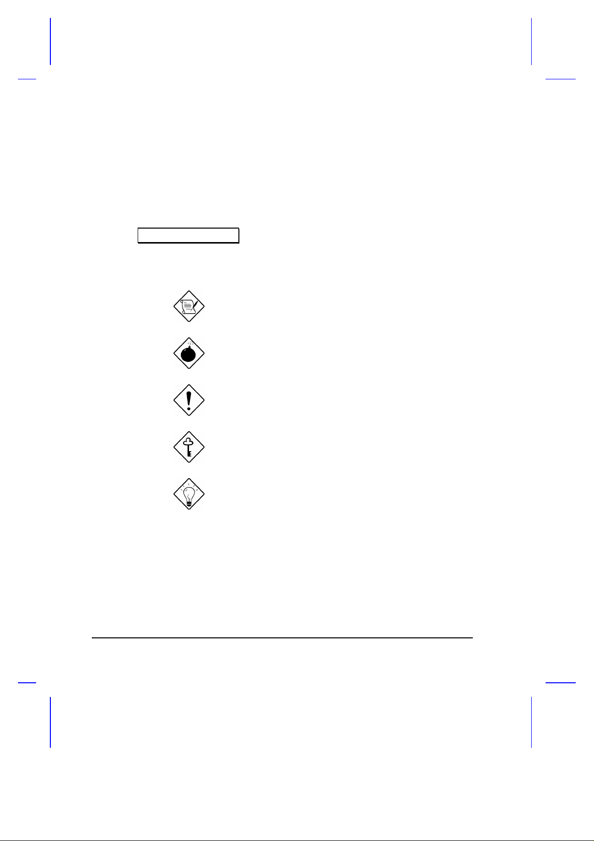
1.2.1 Notebook
Do not expose the notebook to
direct sunlight. Do not place
near sources of heat, such as a
radiator.
Do not expose to temperatures
below 0ºC (32ºF)
or
above 50ºC (122ºF).
Getting Started 1-3
Page 19
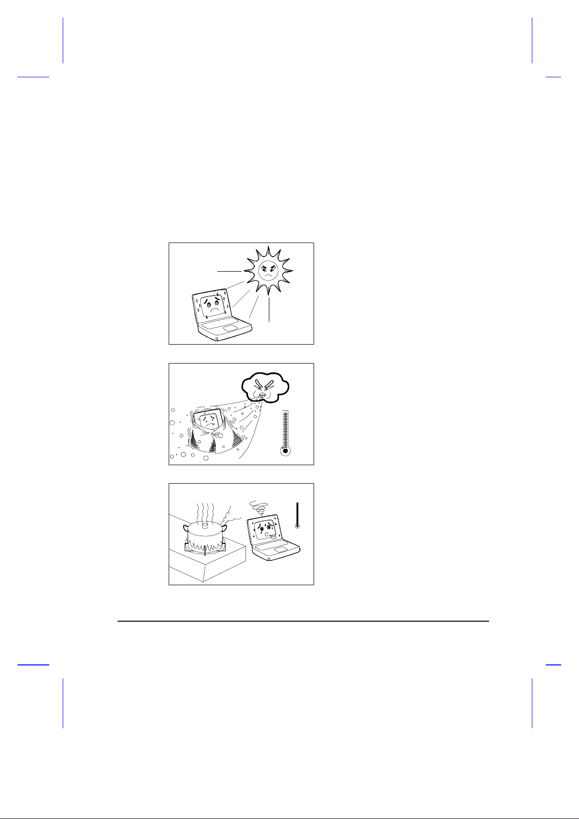
•
Do not subject the notebook to
•
•
•
magnetic fields.
Do not expose the notebook to
rain or moisture.
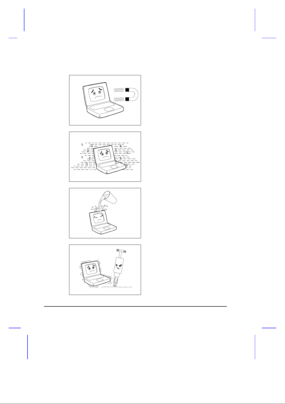
Do not spill water on the
notebook.
Do not subject the computer to
heavy shock and vibration.
1-4 User’s Manual
Page 20
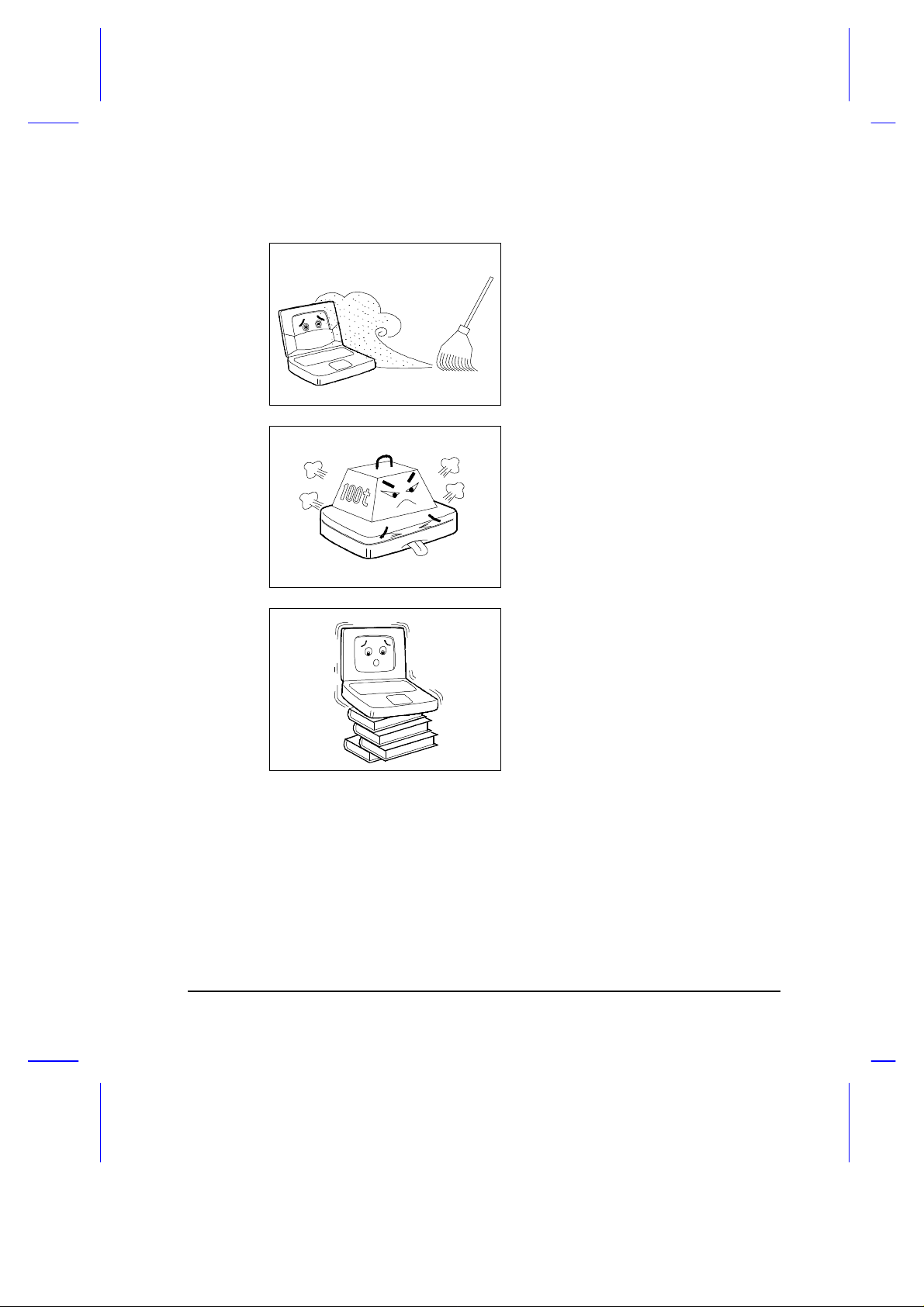
•
Do not expose the notebook to
•
•
dust and dirt.
Never place objects on top of
the notebook to avoid
damaging the notebook.
Never place the notebook on
uneven surfaces.
Getting Started 1-5
Page 21

1.2.2 AC Adapter
Here are some ways of taking care of your AC adapter.
• Do not connect the adapter to any other device.
• Do not step on the power cord or place heavy objects on top of it.
Carefully route the power cord and any cables away from personal
traffic.
• When unplugging the power cord, do not pull on the cord itself but pull
on the plug.
• The total ampere ratings of the equipment plugged in should not
exceed the ampere rating of the cord if you are using an extension
cord. Also, the total current rating of all equipment plugged into a
single wall outlet should not exceed the fuse rating.
1.2.3 Battery Pack
Here are some ways of taking care of your battery pack.
• Use only batteries of the same kind as replacements. Turn the power
off before removing or replacing batteries.
• Do not tamper with batteries. Keep them away from children.
• Dispose of used batteries according to local regulations. Recycle if at
all possible.
1-6 User’s Manual
Page 22

1.2.4 Cleaning and Servicing
When cleaning the notebook, follow these steps:
1. Power off the notebook and remove the battery pack.
2. Disconnect the AC adapter.
3. Use a soft cloth moistened with water. Do not use liquid or aerosol
cleaners.
Contact your dealer or see your service technician if any of the following
occurs:
• Notebook has been dropped or the body has been damaged.
• Liquid has been spilled into the product.
• The notebook does not operate normally.
See section 7.3 for contact information.
1.2.5 Diskettes
Following are some tips on diskette management:
• Always make backup copies of diskettes that contain important data or
program files.
• Keep diskettes away from magnetic fields and sources of heat.
• Avoid removing a diskette from a drive when the floppy drive activity
light is on.
Getting Started 1-7
Page 23

• Write-protect your diskettes to prevent accidental erasure. To do this,
slide the write-protect tab to the write-protect position.
Write-protected
Not write-protected
Figure 1-1 Write-protecting a 3.5-inch Diskette
• When you put a label on a 3.5-inch diskette, make sure that the label is
properly attached (flat on the surface) and within the labelling area
(area with slight surface depression) on the diskette. An improperly
attached label may cause a diskette to get stuck in the drive when you
are inserting or removing it.
1-8 User’s Manual
Page 24
1.3 Connecting the Notebook
After reading through the previous section, you are now ready to experience
your new AcerNote.
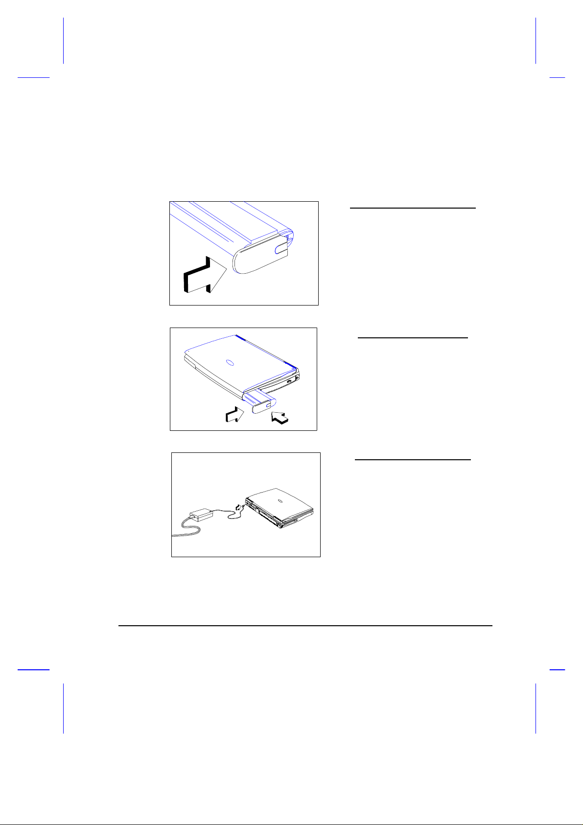
Connecting the Battery Cover
Slide the battery compartment cover
over the battery until both the cover
and the battery are firmly attached.
Inserting the Battery Pack
Insert the battery pack into the
battery compartment and slide the
battery compartment cover in place.
Connecting the AC Adapter
Connect one end of the AC adapter
to the DC-in port on the notebook’s
rear panel and the other end to a
properly grounded power outlet.
Getting Started 1-9
Page 25
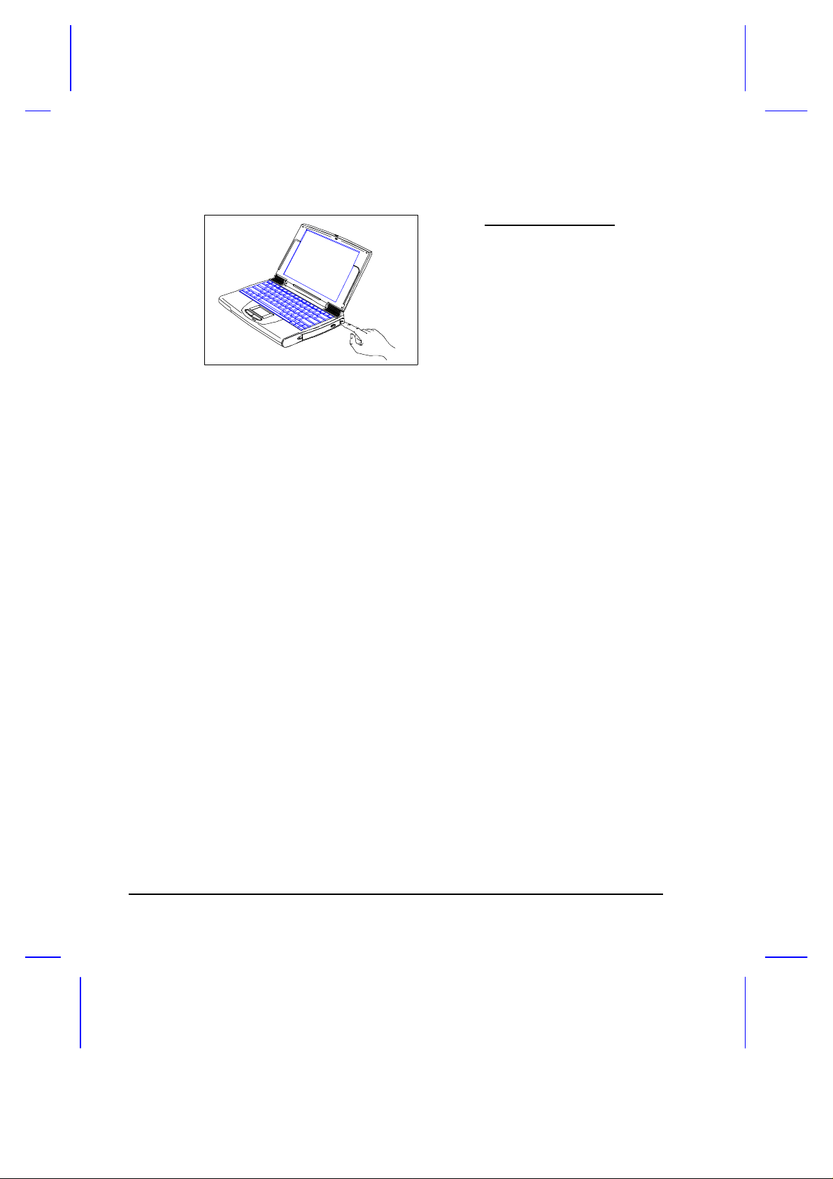
Turning on the Power
Press the power switch to turn on
the power.
The POST (Power On Self-Test) routine executes and Windows 95 begins
loading.
1-10 User’s Manual
Page 26

1.4 Creating Backup and Startup Diskettes for
Windows 95
Entering User Information
When Windows 95 loads for the first time, enter your user information.
Have your Windows 95 serial number ready, found in the Windows 95
documentation package.
Creating Backup and Startup Diskettes
If your Windows 95 package contains a Windows 95 CD-ROM,
you do not need to create backup diskettes.
Windows 95 prompts you to create backup and startup diskettes. Prepare
approximately thirty (30) 3½-inch 1.44MB diskettes for backing up Windows
95 and label them accordingly. Labels are included with the Windows 95
documentation package.
After you are through labelling the disks, begin the backup process.
Do not neglect creating the Windows 95 startup (system)
diskette.
If you do not wish to perform the backup at this time, you can skip through
this step during Windows 95 setup. Access the Create System Disk tool
when you wish to do so. However, we suggest you create these disks as
soon as possible.
Now may be the perfect time to read through the user’s manual and get
familiar with the AcerNote Light Multimedia.
Getting Started 1-11
Page 27

1.5 Getting Help Online
This user’s manual provides clear and concise information about the
notebook, so read it thoroughly. To provide you with help when traveling,
the notebook has a comprehensive online help.
Accessing Online Help
Follow these steps to access the online documentation:
1. Press the Windows logo button or Click on the Start button.
2. Select Programs.
3. Click on AcerNote Light Multimedia.
4. Select Online Help.
The online help is easy to navigate with hypertext and hypergraphics. Clear
illustrations help describe notebook operation as well.
Getting Online
If you are connected to the Internet and have World Wide Web access, visit
our home page (http://www.acer.com/) and get the latest information about
our products.
1-12 User’s Manual
Page 28

System Tour
This notebook combines high-performance, versatility, power management
features and multimedia capabilities in a unique and stylish design case.
Work with unmatched productivity and reliability with your new power
computing partner.
This chapter gives an in-depth “tour” of the notebook’s many features.
Chapter 2
System Tour 2-1
Page 29

2.1 Features
The notebook was designed with the user in mind. Here are just a few of
the notebook’s many features:
Performance
• High-end Pentium microprocessor
• 64-bit main memory
• Large LCD display and PCI local bus video with graphics acceleration
• Internal 3.5-inch floppy drive or CD-ROM drive
• High-capacity, Enhanced-IDE hard disk
• Lithium-Ion or Nickel Metal-Hydride smart battery pack
• Power management system with zero-volt suspend-to-disk functionality
Multimedia
• 16-bit stereo audio
• Built-in dual speakers
• Ultra-slim, high-speed CD-ROM drive
1
Some areas or regions may not offer the AcerNote Light Multimedia with a built-in CD-ROM drive.
2-2 User’s Manual
1
Page 30

Human-centric Design and Ergonomics
• Lightweight and slim
• Sleek, smooth and stylish design
• Full-sized keyboard
• Wide and curved palm rest
• Centrally-located touchpad pointing device
Expansion
• PC card (formerly PCMCIA) slots (two type II/I or one type III) with ZV
(Zoomed Video) port support
• Upgradeable memory, hard disk and CPU
System Tour 2-3
Page 31

2.2 Display
The large graphics display offers excellent viewing, display quality and
desktop performance graphics. The notebook supports two different display
configurations — DualScan STN and TFT active matrix.
Video Performance
PCI local bus video with graphics accelerator and 1MB video RAM boost
video performance.
Simultaneous Display
The notebook’s large display and multimedia capabilities are great for
giving presentations. If you prefer, you can also connect an external
monitor when giving presentations. This notebook supports simultaneous
LCD and CRT display. Simultaneous display allows you to control the
presentation from your notebook and at the same time face your audience.
You can even connect an LCD projection panel for large-audience
presentations.
Power Management
The power management system incorporates an “automatic LCD dim”
feature that automatically decides the best settings for your display and at
the same time conserve power. See section 3.2 for more information on
power management.
Opening and Closing the Display
To open the display, slide the display lid latch to the left and lift up the lid.
Then tilt it to a comfortable viewing position.
The notebook employs a microswitch that turns off the display to conserve
power when you close the lid, and turns it back on when you open the lid.
2-4 User’s Manual
Page 32

Microswitch
Figure 2-1 Display
To close the lid, fold it down gently until the display lid latch clicks into
place.
To avoid damaging the display, do not slam it when closing.
Do not place any object on top of the notebook when the
display is closed.
System Tour 2-5
Page 33

2.3 Indicator Light
A two-way indicator light is found on the inside and outside of the display.
See figure below.
Figure 2-2 Indicator Light
This two-way indicator light allows you to see the notebook status when the
display is open or closed. The indicator serves both as a power and batterycharging indicator. See Table 2-1.
Table 2-1 Indicator Status Descriptions
Indicator
Light
Indicator
Light
Indicator Status Power Condition
Green On Charged battery is installed or a power AC adapter
is connected to the notebook.
Red Off Battery is installed and a powered AC adapter is
connected to the notebook and charging the battery
(rapid charge mode).
Orange On Battery is installed and a powered AC adapter is
connected to the notebook and charging the battery
(charge-in-use mode).
Flashing On Battery is running low on power and no AC adapter
is connected to the notebook.
To find out more about batteries, see Chapter 3.
2-6 User’s Manual
Page 34

2.4 Keyboard
The keyboard has full-sized keys that includes an embedded keypad,
separate cursor keys, two Windows 95 keys and twelve function keys.
2.4.1 Keyboard Layout and Special Keys
Keyboard Layout
Figure 2-3 Keyboard Layout
System Tour 2-7
Page 35

Lock Keys
The keyboard has three lock keys which you can toggle on and off. See
Table 2-2 for the lock key descriptions.
Table 2-2 Lock Key Descriptions
Lock Key Description
@ When the Caps Lock indicator is on, all alphabetic characters
typed are in uppercase.
- [ When the Scroll Lock indicator is on, the screen moves one line up
- ] When the Num Lock indicator is on, the embedded keypad is in
or down when you press w or y respectively. Scroll lock does not
work with some applications.
numeric mode. The keys function as a calculator (complete with
arithmetic operators +, -, *, and /).
Use this mode when you need to do a lot of numeric data entry. A
better solution would be to connect an external keypad.
2-8 User’s Manual
Page 36

Embedded Keypad
The embedded keypad functions like a desktop numeric keypad. It is
indicated by small, encircled characters located on the upper right corner of
the keycaps. To simplify the keyboard legend, the cursor-control key
symbols are not printed on the keys. Table 2-3 tells how to use the
embedded keypad.
Table 2-3 Using the Embedded Keypad
Desired Access Num Lock On Num Lock Off
Number keys on
embedded keypad
Cursor-control keys
on embedded keypad
Main keyboard keys Hold while typing letters
Type numbers in a normal
manner.
Hold j while using cursorcontrol keys.
on embedded keypad.
Hold while using the
number keys.
Hold and j while using
cursor-control keys.
Type the letters in a
normal manner.
If an external keyboard or keypad is connected to the
notebook, the numlock function only works on the external
keyboard or keypad.
System Tour 2-9
Page 37

Windows 95 Keys
The keyboard has two keys that perform Windows 95-specific functions.
See Table 2-4.
Table 2-4 Windows 95 Key Descriptions
Key Description
Windows logo key Start button. Combinations with this key performs special
functions. Below are a few examples:
• Windows + Tab Activate next Taskbar button
• Windows + E Explore My Computer
• Windows + F Find Document
• Windows + M Minimize All
• Shift + Windows + M Undo Minimize All
• Windows + R Display Run dialog box
Application key Opens the application’s context menu (same as right-click).
2-10 User’s Manual
Page 38

Hot Keys
The notebook employs hot keys or key combinations to access most of the
notebook’s controls like screen contrast and brightness, volume output and
the BIOS setup utility.
Table 2-5 Hot Key List
Hot Key Function Description
-| Hotkey Escape Exits the hotkey control.
-l Hotkey Help Displays the hotkey list and help.
-m Brightness
Control
Contrast Control
Toggles between brightness control and contrast
control.
Press the scale hotkeys ( -x and -z) to
increase and decrease the brightness or contrast
level.
Notebooks with TFT displays do not show the
brightness control icon.
-n Display Toggle Switches display from LCD to CRT to both LCD
-o Battery Gauge Toggles the battery gauge display.
and CRT.
System Tour 2-11
Page 39

Table 2-5 Hot Key List (continued)
Hot Key Function Description
-p Volume Control Press the scale hotkeys ( -x and -z) to
-q Setup Gains access to BIOS Setup’s Advanced System
-r Suspend/Standby Enters suspend mode if the 0-volt suspend
-x Scale Increase Increases the setting of the current icon.
-z Scale Decrease Decreases the setting of the current icon.
increase and decrease the output level.
Configuration parameters. See section 6.4.
function is installed and enabled; otherwise, the
notebook enters standby mode.
Activating and Using Hot Keys
When activating hot keys, press and hold the first key before pressing
the other keys in the hot key combination.
Some hot keys pop-up an onscreen icon as shown in Table 2-5. For hot
keys with pop-up icons, press the scale hot keys ( -x and -z) to
increase and decrease the setting of the current icon.
Exiting Pop-up Icons and Screens
Press hot key escape ( -|) to exit a pop-up icon resulting from a hot key.
Press | to exit a screen resulting from a hot key.
2-12 User’s Manual
Page 40

2.4.2 Keyboard Ergonomics
Located below the keyboard, the wide and curved palm rest gives you a
place to rest your hands while you type.
Figure 2-4 Palm Rest
System Tour 2-13
Page 41

2.5 Touchpad
The built-in touchpad is an PS/2-compatible pointing device that senses
movement on its surface. This means the cursor responds as you move
your finger on the surface of the touchpad. The central location on the palm
rest provides ample comfort and support.
Figure 2-5 Touchpad
The touchpad works with most mouse drivers, but the bundled
touchpad driver supports special functions that work uniquely
with the touchpad. See section 5.3 for details.
2-14 User’s Manual
Page 42

Touchpad Basics
The following items teach you how to use the touchpad:
• Move your finger across the touchpad to move the cursor.
• Press the left and right buttons located on the edge of the touchpad to
do selection and execution functions. These two buttons are similar to
the left and right buttons on a mouse. Tapping on the touchpad
produces similar results. See Table 2-6.
Table 2-6 Touchpad Functions
Function Left Button Right Button Tap
Execution Click twice
quickly
Selection Click once Tap once
Drag Click and
hold to drag
the cursor
Access
Context
Menu
Click once - none -
Tap twice (at the same speed as
double-clicking the mouse button)
Tap twice (at the same speed as
double-clicking the mouse button)
and hold finger to the touchpad on
the second tap to drag the cursor
Keep your fingers dry and clean when using the touchpad. Also
keep the touchpad dry and clean.
The touchpad is sensitive to finger movements. Hence, the
lighter the touch, the better the response. Tapping too hard will
not increase the touchpad’s responsiveness.
System Tour 2-15
Page 43

2.6 Storage
High-capacity storage comes in the form of a 2.5-inch Enhanced-IDE hard
disk. The notebook also has either an internal 3.5-inch, 1.44MB floppy
drive or an internal high-speed CD-ROM drive. PC Card slots are found on
the left panel of the notebook.
2.6.1 Hard Disk
The hard disk module can be upgraded when you need more storage space.
See section 4.9.2 for details.
2.6.2 Internal Media
The notebook comes with either a floppy drive or CD-ROM drive installed.
Internal Floppy Drive Model
Figure 2-6 Internal Drive
The CD-ROM drive gives you portable multimedia access. An external
floppy drive is available for models with built-in CD-ROM drives.
2-16 User’s Manual
Internal CD-ROM Drive Model
Page 44

External Floppy Drive
Follow these steps to use the external floppy drive:
1. Press the power switch to turn
off the power.
2. Connect one end of the FDD
cable to the floppy drive port
and the other end to the
external floppy drive connector.
After turning on the power, the notebook automatically senses the external
floppy drive.
System Tour 2-17
Page 45

2.6.3 PC Card Slots
There are two type II/I or one type III PC Card slots found on the left panel
of the notebook. These slots accept credit-card-sized cards that enhances
the usability and expandability of the notebook.
PC Cards (formerly PCMCIA) are add-on cards for portable computers,
giving you expansion possibilities long afforded by desktop PCs. Popular
type II cards include flash memory, SRAM, fax/data modem, LAN and SCSI
cards. Common type III cards are 1.8-inch ATA drives and cellular
modems.
ZV (Zoomed Video) port support allows your system to support hardware
MPEG in the form of a ZV PC card.
Refer to your card’s user’s manual for details on how to install
and use the card and its functions.
Inserting a Card
Insert the card into the desired slot
and make the proper connections
(e.g., network cable), if necessary.
See your card manual for details.
For type III and ZV cards, insert
card into the lower slot.
2-18 User’s Manual
Page 46

Ejecting a Card
Exit the application using the card, then follow these steps:
Pull out the slot eject button of the
slot where the card is inserted.
Press the slot eject button to eject
the card.
System Tour 2-19
Page 47

2.7 Ports
Ports allow you to connect peripheral devices to your notebook computer as
you would with a desktop PC. The ports are found on the rear panel.
See Chapter 4 on how to connect external devices to the
notebook.
1 DC-in Port 6 Serial Port
2 Microphone-in Port 7 Parallel Port
3 Line-in Port 8 External CRT Port
4 Line-out Port 9 PS/2 Port
5 External Floppy Drive Connector
Figure 2-7 Ports and Connectors
2-20 User’s Manual
Page 48

Table 2-7 describes these ports.
Table 2-7 Port Descriptions
# Icon Port Connects to...
1 DC-in Port AC adapter and power outlet
2 Microphone-in Port External 3.5mm minijack
condenser microphone
3 Line-in Port Line-in device (e.g., audio CD
player, stereo walkman)
4 Line-out Port Line-out device
(e.g., speakers, headphones)
5 External Floppy Drive
Connector
6 Serial Port
(UART16650-compatible)
7 Parallel Port
(EPP/ECP-compliant)
8 External CRT port Monitor
9
PS/2 Port PS/2-compatible device
External floppy drive
Serial device
(e.g., serial mouse)
Parallel device
(e.g., parallel printer)
(up to 1024x768, 256-colors )
(e.g., PS/2 keyboard,
keypad, mouse)
System Tour 2-21
Page 49

2.8 Audio
Standard notebook configuration includes 16-bit stereo audio and built-in
dual speakers. The dual speakers found on both sides of the display hinge
direct sound towards you which allows for excellent sound output.
Speakers
Speakers
Figure 2-8 Built-in Speakers
Besides the built-in speakers, there are audio ports on the rear panel of the
notebook. See section 4.6 for more information.
2-22 User’s Manual
Page 50

2.9 Securing your Notebook
Security features include hardware and software locks — a security notch
and a two-level password scheme.
2.9.1 Security Notch
A security notch located on the rear panel of the notebook lets you connect
a standard key-based computer security lock.
2.9.2 Passwords
Circle or wrap a computer security
lock cable around an immovable
object such as a table or locked
drawer handle. Insert the lock into
the notch and turn the key to secure
the lock.
A two-level password scheme protects your notebook from unauthorized
access. When set, no one can access the notebook without entering the
correct password. For information on how to set passwords, see section
6.5.8.
System Tour 2-23
Page 51

Power
The notebook operates on AC or battery power. This chapter contains the
information you need to know to operate the notebook on battery power. It
also includes information about the power management system.
Chapter 3
Power 3-1
Page 52

3.1 Battery Pack
The notebook uses a smart battery pack that gives you longer use between
charges.
3.1.1 Battery Pack Characteristics
The battery pack has the following characteristics:
• Employs Current Battery Technology Standards The notebook uses
either a Lithium-Ion or Nickel Metal-Hydride (NiMH) battery pack.
These battery types do not have the memory effect problem of Nickel
Cadmium (NiCd). NiMH and especially Li-Ion batteries consistently
provide the longest battery life, best-suited for road warriors.
• Onscreen Battery Gauge An onscreen battery gauge allows you to
check the battery charge level.
• Battery-low Warning When the battery charge level becomes low, the
notebook gives off warning beeps and the status indicator flashes at
regular intervals. This tells the user that the battery power is critically
low. You can correct this situation by recharging the battery pack.
Whenever possible, use the AC adapter. The battery will come in handy
when you travel or during a power failure. It is advisable to have an extra
fully-charged battery pack available for backup.
Currently, there is no defined standard for measuring battery life. Several
factors have made it almost impossible to compare the battery life of
different notebooks based on specifications alone. These factors include
different implementations of power saving/management systems,
applications in use, the user’s “usage pattern”, hard disk capacity and
access frequency, LCD size and brightness, system form factor and weight.
3-2 User’s Manual
Page 53

If the system is to be stored for more than two weeks, we
suggest that you remove the battery pack. Battery power (from
a fully charged battery pack) depletes in roughly ten days with
the notebook in standby mode. When power is off, battery
power depletes in one month.
Do not expose battery packs to temperatures below 0ºC (32ºF)
or above 60ºC (140ºF). This may adversely affect the battery
pack.
3.1.2 Removing and Installing the Battery Pack
Removing the Battery Pack
Before removing the battery pack, make sure that you have an AC adapter
connected to the notebook; otherwise turn off the notebook.
The following figure illustrates how to remove the battery pack.
Press the battery compartment
cover release button and slide out
the cover.
Then pull out the battery pack.
Power 3-3
Page 54

Installing the Battery Pack
The following figure shows how to install the battery pack.
3.1.3 Charging the Battery
To charge the battery, place the battery pack inside the battery
compartment and plug the AC adapter into the notebook and an electrical
outlet. You can also purchase an optional external battery charger to
charge the battery pack (see section 4.8.3 for details).
Charging Modes
Insert the battery pack into the
battery compartment and slide in the
battery compartment cover.
The adapter has three charging modes:
• Rapid mode
The notebook uses rapid charging when power is turned off and a
powered AC adapter is connected to it. In rapid mode, a fully depleted
battery gets fully charged in approximately two hours.
• Charge-in-use mode
When the notebook is in use with the AC adapter plugged in, the
notebook also charges the battery pack if installed. This mode will take
longer to fully charge a battery than rapid mode. In charge-in-use
mode, a fully depleted battery gets fully charged in approximately six
to eight hours.
3-4 User’s Manual
Page 55

• Trickle mode
When the battery is fully charged, the adapter changes to trickle mode
to maintain the battery charge level. This prevents the battery from
draining while the notebook is in use.
We suggest that you charge the battery pack before retiring,
letting it charge overnight before traveling. This ensures a fully
charged battery for use the next day.
3.1.4 Checking the Battery Level
The notebook features battery-low warning signals that are both audible and
visible. When the battery pack is low, the notebook emits warning beeps
and the battery indicator flashes at regular intervals. Also, you can check
the battery charge level using the onscreen battery gauge.
Using the Onscreen Battery Gauge
To access the onscreen battery gauge, press -o. The
battery level icon displays onscreen.
The onscreen battery gauge indicates the present battery level.
Power 3-5
Page 56

3.1.5 Optimizing Battery Life
This section helps you get the most out of battery operation. Optimizing
battery life prolongs the charge/recharge cycle and improves recharge
efficiency. Follow these suggestions to optimize and maximize battery
power:
• Purchase an extra battery pack.
• Use the Sleep Manager utility to reserve hard disk space for the
suspend function. See section 5.2.
• Use the AC adapter whenever possible so that the battery is reserved
for on-the-go computing.
• Keep the battery pack in the notebook powered by the AC adapter.
The constant trickle charge maintains the battery level to eliminate the
battery self-discharge effect. The charge-in-use function also charges
the battery pack.
• Disable the parallel and serial ports if no devices are connected to
these ports. You can do this through Setup. See sections 6.5.5. and
6.5.6.
• Eject the PCMCIA card from the card slot when not in use, since the
PCMCIA card draws extra power.
• Store the battery pack in a cool, dry place. The recommended storage
temperature for battery packs ranges from 10 to 30 degrees C. The
higher the storage temperature, the faster the battery pack selfdischarges.
• The batteries can be recharged about 500 times when used as
directed. Excess recharging decreases battery life.
• Take care of your battery pack and AC adapter. See sections 1.2.2
and 1.2.3 for details.
3-6 User’s Manual
Page 57

3.1.6 Battery-low Warning
You never have to worry about battery power as long as you are using the
AC adapter. However, when you operate the notebook on battery power,
pay extra attention to the warning beeps and the indicator light on the
display panel. The indicator flashes when the battery power is low.
The following signals indicate a battery-low condition:
• The buzzer generates four short beeps every minute, if you enabled
the Battery-low Warning Beep parameter in Setup
• The status indicator flashes at regular intervals until battery power is
depleted
When you receive a battery-low warning, you have around three minutes to
save your work. If you do not connect the AC adapter within this period, the
notebook enters suspend mode if the Suspend upon Battery-low parameter
in Setup is enabled and the following conditions exist:
• There is enough battery power left to save system information onto the
hard disk.
• The reserved disk space for saving these data is larger than the
combined system and video memory size.
Otherwise, the notebook enters standby mode.
Connect the AC adapter or insert a charged battery pack into
the notebook as soon as possible. Data is lost when notebook
power is cut off during standby mode.
Power 3-7
Page 58

Table 3-2 lists the recommended course of action when you encounter a
battery-low condition.
Table 3-2 Course of Action for Battery-low Condition
Situation Recommended Action
AC adapter and power
outlet available
An extra fully-charged
battery pack available
AC adapter or power
outlet not available
1. Connect the AC adapter to the system.
2. Save all necessary files.
3. Resume work.
4. Power off the notebook if you wish to recharge
the battery rapidly.
1. Save all necessary files.
2. Exit the application.
3. Power off the notebook.
4. Replace the battery pack.
5. Power on the notebook and resume work.
or
1. Save all necessary files.
2. Enter suspend mode.
3. Install the extra battery pack.
4. Resume from suspend mode.
1. Save all necessary files.
2. Exit the application.
3. Power off the notebook.
or
1. Save all necessary files.
2. Enter suspend mode.
3-8 User’s Manual
Page 59

3.2 Power Management
This notebook has a built-in power management unit that monitors system
activity. System activity refers to any activity involving one or more of the
following devices: keyboard, mouse, floppy drive, hard disk, peripherals
connected to the serial and parallel ports, and video memory. If no activity
is detected for a specified period of time (called an inactivity time-out), the
system switches to one of the power-saving modes to conserve energy.
These power-saving modes are display standby mode, fixed disk standby,
and standby/suspend mode.
The Setup utility allows you to specify the inactivity time-out.
The power management function may not work when the
cursor is emulated by software such as Chinese system
(ETv3.1), Japanese system (DOS/V), Word for Windows, etc.
3.2.1 Power Management Modes
Display Standby Mode
Screen activity is determined by the keyboard, the built-in touchpad, and an
external PS/2 pointing device. If these devices are idle for the period
specified by the Display Standby Timer, the display shuts off until you press
a key or move the touchpad or external mouse.
We strongly recommend you to enable the Display Standby
Timer with a shorter time interval to prolong your battery life.
“Automatic Dim” Feature
The notebook has a unique “automatic dim” power saving feature. When
the notebook is using AC power and you disconnect the AC adapter from
the notebook, the system “decides” whether or not to automatically dim the
LCD backlight to save power.
Power 3-9
Page 60

If the LCD backlight is too bright, the system automatically adjusts it to a
manageable level; otherwise, the level stays the same. If you want a
brighter picture, you can then adjust the brightness and contrast level using
hotkeys ( -m1).
If you reconnect AC power to the system, the system automatically adjusts
the LCD backlight to its original level — the brightness and contrast level
before disconnecting the AC adapter. If you adjusted the brightness and
contrast level after disconnecting AC power, the level stays the same after
you reconnect the AC adapter.
Fixed Disk Standby Mode
The hard disk enters standby mode when there are no disk read/write
operations within the period of time specified by the Fixed Disk Standby
Timer. In the standby state, the power supplied to the hard disk is reduced
to a minimum. The hard disk returns to normal once the system accesses
it.
Suspend Mode
In suspend mode (also known as zero-volt suspend-to-disk mode), power
shuts off. The notebook saves all system information onto the hard disk
before it enters suspend mode. Once you turn on the power, the notebook
restores this information and resumes where you left off upon leaving
suspend mode.
A necessary condition for the notebook to enter suspend mode is that the
reserved space for saving system information on the hard disk must be
larger than the combined system and video memory size. Under such
conditions, the standby/suspend hot key acts as the suspend hot key. See
section 5.2 for information on the Sleep Manager utility.
1
After pressing this key combination, press -x and -z to increase and decrease the current setting.
Press - | to close the pop-up.
3-10 User’s Manual
Page 61

In this situation, there are four ways to enter suspend mode:
• Press the standby/suspend hot key
If the notebook beeps but does not enter suspend mode after
pressing the standby/suspend hot key, it means the operating
system does not allow the notebook to enter the power saving
mode.
-r ( )
• Set a value for the System Standby/Suspend Timer in Setup. If the
waiting time specified by this time elapses without any system activity,
the system goes into suspend mode
• Enable the Suspend upon Battery-low parameter in Setup. If a battery-
low condition takes place, the notebook enters suspend mode in about
five minutes. See section 3.1.6.
• Invoked by the operating system power saving modes
When the notebook enters suspend mode, the whole system does not
consume any power. This is why suspend mode is also called zero-volt
suspend.
To exit suspend mode, press the power switch ( ).
Do not change any system devices when the notebook is in
suspend mode.
If the notebook is connected to a LAN environment or has a
current PCMCIA modem connection, it does not resume
connection even after the notebook returns to normal operating
mode.
Power 3-11
Page 62

Standby Mode
The notebook consumes very low power in standby mode. Data remain
intact in the system memory.
The necessary condition for the notebook to enter standby mode is that the
reserved disk space size for saving system and video memory is insufficient
so the notebook is unable to enter suspend mode.
In this situation, there are three ways to enter standby mode:
• Press the standby/suspend hot key
If the notebook beeps but does not enter standby mode after
pressing the standby/suspend hot key, it means the operating
system does not allow the notebook to enter the power saving
mode.
-r ( )
• Set a value for the System Standby/Suspend Timer in Setup. If the
waiting time specified by this timer elapses without any system activity,
the notebook goes into standby mode.
• Invoked by the operating system power saving modes
The following signals indicate that the notebook is in standby mode:
• The buzzer beeps (when you press the standby/suspend hot key)
• The status indicator ( ) flashes
Unstored data is lost when you turn off the notebook power in
standby mode.
3-12 User’s Manual
Page 63

To leave standby mode and return to normal mode, press the any key. If an
incoming PCMCIA modem event occurs and the Modem Ring Wake Up
From Standby is enabled, the system returns to normal mode.
If the notebook is connected to a LAN environment or has a
current PCMCIA modem connection, it does not resume
connection even after the notebook returns to normal operating
mode.
3.2.2 Advanced Power Management (APM)
This notebook supports the APM standard designed to further reduce
system power consumption. APM is a power-management approach
defined jointly by Microsoft and Intel. An increasing number of software
supports APM to take advantage of power saving features and allows
greater system availability without degrading performance.
DOS
You can use the APM feature under the DOS environment by including the
POWER.EXE command in the CONFIG.SYS file. See the MS-DOS
manual for instructions on how to edit the CONFIG.SYS file. For more
information about APM, type the following at the DOS prompt:
HELP POWER.EXE e
Refer to the DOS user’s guide for details.
Windows 3.x
To enable APM under the Windows environment, run Windows Setup and
select MS-DOS System with APM as your computer type in the
System Information menu. Refer to the Windows user’s guide for details.
Power 3-13
Page 64

Windows 95
To enable APM under Windows 95, follow these steps:
1. Select the Start button and click on Settings....
2. Select the Control Panel item.
3. Double-click on the System icon in the Control Panel window.
4. Select the Device Manager tab and double-click on System devices.
5. Double-click on Advanced Power Management support.
If the device is not working properly, select the Settings tab and verify
if the check box for enabling power management support is selected.
Refer to the Windows 95 user’s guide for details.
1. If you enable the Power Management Mode parameter in
Setup without installing the APM under DOS, Windows or
Windows 95, the system time and date do not display the
correct settings after the notebook returns to normal
operation from standby or suspend mode. To update the
time and date, reboot the notebook. Enable APM to avoid
this problem.
2. You can not change any power management parameter in
the Setup screen after APM is enabled because it is
controlled by APM.
Advanced Power Management greatly prolongs battery life.
Use APM whenever possible.
3-14 User’s Manual
Page 65

Options
Your notebook offers excellent expansion capabilities with its built-in ports
and connectors. This chapter describes how to connect peripherals and
hardware options that help you use your notebook computer with ease.
When connecting peripherals, read the manual included with the peripheral
for operating instructions.
This chapter also includes sections on how to upgrade key components.
Key component upgradeability guards your notebook from becoming
obsolete.
Chapter 4
Options 4-1
Page 66

4.1 External Monitor
To show graphical effects on a larger display, open the port cover and
connect an external monitor to the CRT port ( ). Read the monitor
manual for additional instructions.
Figure 4-1 Connecting an External Monitor
4-2 User’s Manual
Page 67

4.2 External Keyboard
This notebook has a keyboard with full-sized keys and an embedded
keypad. If you feel more comfortable using a desktop keyboard, you can
install a PS/2-compatible external keyboard.
To connect an external keyboard, plug the external keyboard into the PS/2
connector (
).
Figure 4-2 Connecting an External Keyboard
Options 4-3
Page 68

4.3 External Keypad
You can also use a 17-key numeric keypad for number-sensitive data entry
applications. To connect the keypad, plug in the keypad connector to the
PS/2 port (
Figure 4-3 Connecting an External Keypad
) at the rear of the notebook.
4-4 User’s Manual
Page 69

4.4 External Pointing Device
This notebook accepts either a serial mouse or PS/2-compatible mouse or
similar pointing device. The built-in touchpad works simultaneously with an
external PS/2 mouse.
If you use a serial mouse, open the port cover and plug it into the serial port
( ). If you use a PS/2-compatible mouse, plug it into the PS/2 port
(
(a) Serial Mouse
).
(b) PS/2 Mouse
Figure 4-4 Connecting an External Pointing Device
Options 4-5
Page 70

4.5 Printer
This notebook supports both serial and parallel printers. For a serial printer,
plug the printer cable into a serial port ( ). For a parallel printer, open
the port cover and plug the printer cable into the parallel port ( ). See
your printer manual for operating instructions.
If the printer does not function, enter Setup and see to it that
the parallel port is enabled. Refer to section 6.5.5 for
assistance.
Figure 4-5 Connecting a Parallel Printer
4-6 User’s Manual
Page 71

4.6 Audio Devices
To connect audio devices, open the mini port cover and plug in an external
microphone, a line-in device and amplified speakers or headphones to the
microphone-in, line-in and line-out ports, respectively.
Figure 4-6 Connecting Audio Devices
Options 4-7
Page 72

4.7 File Transfer Cable
You can use the file transfer cable to transfer data between the notebook
and other computers. Connect the file transfer cable between the two
computers and use your file transfer utility to perform the transfer. See
Chapter 5 for details on how to use the software.
Figure 4-7 Using the File Transfer Cable
4-8 User’s Manual
Page 73

4.8 Additional Power Packs
You can order spare batteries, AC adapter, and an external battery charger.
4.8.1 Battery Pack
Attaching the Battery Compartment Cover
It is good practice to have a spare
battery around, especially when you
travel. The NiMH and Li-Ion smart
batteries, coupled with power
management features, supply you
with more power on-the-go.
1. Position the battery compartment
cover over the battery pack.
2. Using a little force, slide the
battery compartment cover over
the battery until both the cover
and the battery are firmly
attached. See figure on the left.
Options 4-9
Page 74

Detaching the Battery Compartment Cover
4.8.2 AC Adapter
Slightly pull up the battery
compartment cover release latch
and slide out the cover.
The compact AC adapter charges
your battery pack and supplies
power to your notebook.
4-10 User’s Manual
Page 75

4.8.3 External Battery Charger
AC Adapter Connector
The external battery charger allows you to fully recharge your NiMH and/or
Li-Ion battery packs in a shorter period of time. It also automatically
discharges the battery pack before charging for optimum recharge
efficiency.
Charge/Discharge Button
Battery Charger
Connector
Discharging LED
Charging LED
Figure 4-8 External Battery Charger
Options 4-11
Page 76

Using the External Battery Charger
Follow these steps:
1. Plug the AC adapter into a power
outlet.
2. Connect the AC adapter to the
external battery charger.
3. Attach the battery pack to the
battery charge connector.
The charging LED lights up. The external battery charger automatically
turns off after fully recharging the battery pack.
4-12 User’s Manual
Page 77

4.9 Key Component Upgrades
The notebook delivers superior power and performance. However, some
users and the applications they use may demand more. This notebook
allows you to upgrade your key components when you need increased
performance.
Contact your authorized dealer if you decide to perform a key
component upgrade.
4.9.1 Memory Upgrade
Memory is upgradeable from 8 to 64 MB, employing 8-/16-/32-MB1 64-bit
SO DIMMs (Small Outline Dual Inline Memory Modules). The following
table lists all possible memory configurations.
Table 4-1 Memory Configurations
Slot 1 Slot 2 Total Memory
8 MB 0 MB 8 MB
0 MB 8 MB 8 MB
8 MB 8 MB 16 MB
16 MB 0 MB 16 MB
0 MB 16 MB 16 MB
16 MB 8 MB 24 MB
8 MB 16 MB 24 MB
16 MB 16 MB 32 MB
32 MB 0 MB 32 MB
0 MB 32 MB 32 MB
32 MB 8 MB 40 MB
1
You can upgrade memory using 32-MB DIMMs when these become available. Consult your dealer.
Options 4-13
Page 78

Table 4-1 Memory Configurations (continued)
Slot 1 Slot 2 Total Memory
8 MB 32 MB 40 MB
32 MB 16 MB 48 MB
16 MB 32 MB 48 MB
32 MB 32 MB 64 MB
After installing the memory modules, the system automatically detects and
reconfigures the total memory size during the POST routines.
4.9.2 Hard Disk Upgrade
You can upgrade your hard disk with a higher capacity drive when you need
more storage space. The notebook uses a 12.5mm, 2.5-inch Enhanced-IDE
hard disk that is auto-detected or user-defined. The following table shows
the available, supported hard disks.
Table 4-2 Hard Disk List
Vendor Model Capacity
Hitachi DK223A-81 810 MB
Seagate ST9810AG 810 MB
Toshiba MK1301MAV 1.3 GB
Use the blank spaces to record additional hard disks that will be available in
the future.
4.9.3 CPU Upgrade
The CPU (central processing unit) of the notebook is upgradeable, allowing
you to take advantage of supported, higher-performance CPUs.
4-14 User’s Manual
Page 79

Options 4-15
Page 80

Software
The notebook comes pre-loaded with software and system utilities. This
chapter discusses these system utilities1, their features and functions.
Chapter 5
1
System utilities may differ according to system configuration.
Software 5-1
Page 81

5.1 System Software
The notebook comes preloaded with the following software:
• Windows 95
1
• System utilities
• Suspend-to-disk utility
• Touchpad driver
• Display drivers
• Audio drivers and applications
• Enhanced-IDE driver
• CD-ROM drivers
• Application software
• PC Card slot drivers and applications
• Other third-party application software
The following sections discusses the software and how they work. You can
also make use of the online help provided by the software.
Accessing the Applications
To access most of the software applications, click on the Start button and
select the application folder. Then click on the application icon to run the
selected application.
2
1
In some areas, a different operating system may be pre-loaded instead of Windows 95.
2
The third-party application software list may vary.
5-2 User’s Manual
Page 82

5.2 Sleep Manager
Notebooks usually feature built-in power-saving functions. In addition to the
normal standby mode for power-saving, Acer notebooks are also capable of
a power management feature called 0-volt suspend to hard disk. When a
suspend event occurs, this built-in function saves all the system’s current
status onto your hard disk in the form of a file. The system then shuts off
the power. When the user resumes (pressing the power switch), the system
will restore the data from the hard disk and resume from where you left off
upon leaving suspend mode.
Sleep Manager is a utility that reserves hard disk space needed to
successfully perform the suspend-to-disk feature. The user can use this
utility to create a contiguous area that resides on the hard disk. Once the
reserved space is created, the notebook will be capable of the “0-Volt
Suspend to Hard Disk” feature. User can also use this utility to remove the
reserved space from the disk. In this case, the machine will not be able to
enter 0-volt suspend mode.
Sleep Manager is functionally-connected with the Advanced Power
Management (APM) system of Microsoft Windows. Sleep Manager uses
many advanced APM functions. Sleep Manager is capable of auto-create
and auto-recover features. If the system memory size was changed or the
reserved space on the hard disk was corrupted, Sleep Manager will
reallocate the hard disk space for you automatically.
5.2.1 Accessing the Sleep Manager
There are two ways to bring up the Sleep Manager:
• Taskbar. Double-click on the Sleep Manager status icon if enabled.
• Start menu
1. Click on the Start button.
2. Select Programs.
3. Select 0V Suspend Utilities.
4. Select Sleep Manager.
Software 5-3
Page 83

The Sleep Manager displays below:
5-4 User’s Manual
Page 84

Table 5-1 Sleep Manager Window Items
Item Description
Buttons Click to access the Sleep Manager functions
Current Setting Displays the drive and size of the current reserved space
created by Sleep Manager.
On Board Information Displays the different areas of system memory and their
respective sizes. These system resources need to be
stored before the system can enter 0-volt suspend mode,
so the system can resume to the previous state
successfully.
These system resources are the contents of:
• Onboard memory (DRAM or dynamic memory)
• Video RAM (VRAM or video memory)
• SMRAM (static memory)
• Others
The total size of these system resources shows as the
recommended size in the dialog box.
Recommended Size Displays the minimum size of the contiguous space you
need for the 0-volt suspend-to-disk feature. The actual
size may be a little bit more due to file system alignment.
Enable Indicator on
the Taskbar
When this checkbox is checked, the Sleep Manager
status appears on the taskbar.
Double-click on the Sleep Manager status icon on the
taskbar to bring up the main program, or simply rest your
mouse pointer on the icon to display the current status.
Software 5-5
Page 85

5.2.2 Sleep Manager Functions
Create
The main purpose of Sleep Manager is to find and reserve a contiguous
area on the hard disk. The user can allocate the space themselves by using
the ‘Create’ function on the Sleep Manager utility. Once a suspend event
occurs, the system will enter the suspend mode. If the user did not create
the space or the system DRAM size been changed, Sleep Manager is
invoked and begins the process of creating a space for the system.
When you click on the Create button, a dialog box pops up:
You can select OK to automatically create space for the 0-volt suspend
feature. Sleep Manager displays the recommend size based on onboard
system information. You can also choose Advance>>> to manually set the
space settings and size. The advanced screen shows below.
5-6 User’s Manual
Page 86

Sleep Manager automatically checks the system configuration and displays
the recommended size. The drive where the space will be created is
defined by the system and will be the first available logical drive which has
the requested contiguous free disk space on it. The recommended size is
the minimum size needed to save the current system status.
If the program cannot find the required space on the hard disk during the
space creation process, it shows a message box to inform the user.
Not Enough Space for Allocation
This is a common error message that appears when Sleep Manager is
creating the space on the hard disk. There are several different reasons
that may cause this error. One of the reasons is that the size of the free
disk space on the specific drive is less than the required size. For example,
if the onboard memory is 4MB and the VGA memory is 512KB, the total
free disk space required will be 4608KB. If the total free disk space is less
than 4608KB, the user has to delete some unnecessary files from his hard
disk.
Software 5-7
Page 87

Another possible reason is that the hard disk has enough free space, but
this free space exists as small fragments. The free disk space that Sleep
Manager requires needs to be contiguous. To solve this problem, the user
can use tools such as SpeedDisk (Norton Utilities) or Disk Defragmenter
(Windows 95) to compact these free disk spaces. The user can then run
Sleep Manager utility again to reserve the space.
Another factor that causes the error is when the user employs disk
compression utilities. Sleep Manager can work with most compression
software. However, Sleep Manager can only create the space on a host
drive. A host drive stores original file information and will not be
compressed. The free space on the host drive is usually very small, so the
user should use the command provide by these compression software to
enlarge the size of the host (uncompressed) drive for Sleep Manager.
Remove
If the user wants to use or take back the reserved space, he or she can use
the delete function of Sleep Manager by clicking on the Remove button.
The deletion will result in the system not being able to enter 0-volt suspend
mode. Instead, the system will only be able to enter standby mode.
Minimize
The user can minimize Sleep Manager by selecting the Minimize button. If
the Enable indicator on taskbar box is checked, Sleep Manager will then
switch to background by locating itself on the taskbar. You can pop-up the
main program of Sleep Manager again by double-clicking whenever
needed. If the Enable indicator on taskbar bon is not checked, you have to
select the Sleep Manager item from 0-Volt Suspend Utilities menu of Start
button.
5-8 User’s Manual
Page 88

Exit
The user can exit Sleep Manager by selecting the Exit button. Sleep
Manager will then quit and disable the for capability of auto-adjusting the
reserved space size. Disconnecting this feature is NOT recommended.
5.2.3 Running Sleep Manager
Once Sleep Manager is installed on the disk, the system automatically loads
this utility every time you start Windows 95. Sleep Manager resides in the
background by appearing on the taskbar.
To change the settings of Sleep Manager, simply double-click on the Sleep
Manager icon ( )on the taskbar, or run the Sleep Manager program from
the 0-Volt Suspend to Disk Utilities in the Programs menu.
The Sleep Manager icon , by default, appears on the taskbar. A checkbox
in the Sleep Manager main screen determines whether to enable or disable
the icon on the taskbar. When Sleep Manager has not created the space to
be used for 0-volt suspend or if APM is not enabled, the exclamation icon
will appear. If both Sleep Manager has not created the space to be used for
0-volt suspend and APM is not enabled, the icon appears with a red crossed
circle .
Software 5-9
Page 89

5.2.4 Sleep Manager Troubleshooting Tips
The following are the error messages with their corresponding solutions:
1. This machine is not a model with Acer BIOS. Sleep Manager can only
run on a machine with an Acer-compatible BIOS.
Your notebook needs to have a BIOS compatible with the Acer BIOS.
2. This machine does not have a power management unit. You cannot
run Sleep Manager without PMU.
Sleep Manager can only work on notebooks installed with a PMU.
3. The APM driver for Windows is not installed. Use Windows Setup to
install the APM driver before you run Sleep Manager.
Run Windows Setup and redefine your system as MS-DOS System
with APM model. Windows will then install the APM driver for you.
4. Requested disk space is not enough.
If the free space is actually greater than the requested free space but
not contiguous, use the Windows 95 defragment utility Disk
Defragmenter to compact the hard disk drive space. Then run Sleep
Manager again. If you run Sleep Manager under a DoubleSpace
environment, make sure the free space on the host drive is larger than
the required size for Sleep Manager.
5. The [file name] file cannot be found. Please check the distribution
diskette.
The distribution diskette did not contain the file required for the
installation.
5-10 User’s Manual
Page 90

6. The [directory name] directory cannot be created. Enter another
directory or try another drive.
The directory name that the user specified is not valid. Note that the
user can create only one subdirectory at a time.
7. The software has not been successfully installed. You must run Setup
again.
Sleep Manager is not completely installed. Try to install again.
5.2.5 Uninstalling Sleep Manager
Uninstalling Sleep Manager will delete all files and all system information
for Sleep Manager, it loses the capability of auto-adjusting the reserved
space size for the system configuration changes or modifications, though
the 0-volt suspend feature still functions
To uninstall Sleep Manager from the Windows, follow these steps:
1. Quit the Sleep Manager if it is still running.
2. Click on the Start button and select the Control Panels folder from
Settings.
3. Open the Add/Remove Programs Icon.
4. Select the Sleep Manager for Windows 95 and click the Add/Remove...
button.
5. Follow the screen instructions to complete the uninstallation program.
Software 5-11
Page 91

With Sleep Manager installed and the When Lid is Closed
parameter set to [Suspend to Disk], the notebook enters
suspend-to-disk mode when you close the display. The
notebook also enters this mode when battery is critically low,
regardless of the When Lid is Closed parameter setting.
Opening the display returns the notebook to its previous state
prior to entering suspend-to-disk mode.
Do not deactivate or uninstall Sleep Manager and do not
remove or delete the zero-volt suspend/resume file. Otherwise,
the function will not work — the notebook will only enter
suspend-to-memory mode and not suspend-to-disk mode.
5-12 User’s Manual
Page 92

5.3 Touchpad Driver
The touchpad works with most mouse drivers, but the touchpad driver
supports special functions that work uniquely with the touchpad. The
touchpad driver enhances the Mouse dialog box to include these special
features.
5.3.1 Configuring the Touchpad
Follow these steps to configure the touchpad:
1. Click on the Start button, then select Settings...
2. Select Control Panel to display the Control Panel Window.
3. Double-click on the Mouse icon and select TouchPad.
You can configure different aspects of the touchpad. Refer to the online
help for details.
5.3.2 Swapping Buttons for Left and Right Handed Users
Left-handed users may choose to swap left and right buttons. Swapping the
two buttons reverses their functions.
Swapping, however, also causes the touchpad to behave differently for
tapping. Tapping now (once or twice) brings up the context menu instead of
selecting or executing the desired icon or button. In this case, enable the
Corner Taps function. When enabled, tapping on the top right corner of the
touchpad selects or executes the desired icon or button.
If Corner Taps is not enabled, tapping anywhere on the touchpad brings up
the context menu. See Table 5-2.
Software 5-13
Page 93

Table 5-2 Swapped Touchpad Functions
Function Left
Button
Execution Click twice
Selection Click once Tap once on the top right corner of the
Drag Click and
Access
Context
Menu
Click once
or twice
Right
Button
quickly
hold to drag
the cursor
Tap (Corner Taps Enabled)
Tap twice (at the same speed as
double-clicking the mouse button) on
the top right corner of the touchpad
touchpad
Tap twice (at the same speed as
double-clicking the mouse button) on
the top right corner of the touchpad and
hold finger to the touchpad on the
second tap to drag the cursor
Tap once or twice on the touchpad
except on the top right corner
5-14 User’s Manual
Page 94

Setup
Chapter 6
The notebook has a BIOS setup utility that allows you to configure the
notebook and its hardware settings. This chapter tells how to use the Setup
utility and describes each parameter item in the setup screens.
Setup 6-1
Page 95

6.1 When to Use Setup
The notebook is already correctly configured for you and you do not need to
run Setup. If you make any changes to the notebook or you receive an
Equipment Configuration Error message after you turn on the notebook, you
need to run Setup. Run Setup also if you want to do any of the following:
• Change the system date, time or speed
• Add or remove serial and parallel devices
• Change the system boot drive or display device
• Set the video display features
• Set the power-saving modes
• Set, change, or remove a system password
The system configuration values reside in the battery-powered
CMOS RAM.
6-2 User’s Manual
Page 96

6.2 Entering Setup
Press m during POST to enter Setup. The BIOS Utility main screen
displays.
↓↑→←=Move Highlight Bar, ↵=Select, Esc=Exit and Reboot
There are four main menu items:
Setup Utility
Basic System Configuration
Advanced System Configuration
System Security
Load Setup Default Settings
• Basic System Configuration
• Advanced System Configuration
• System Security
• Load Setup Default Settings
Read through the Setup Screen Notes before navigating the Setup screens.
Setup 6-3
Page 97

Setup Screen Notes
• From the main menu, press w, y, z or x to move from one menu item
to another and press e to enter the selected menu.
• When accessing multi-page sections, press } and { to go through the
pages.
• Parameters displayed in low brightness (grayed-out) are not user-
configurable. The system detects and sets the values for these
parameters.
• Press w or y to move from one parameter to another. Press z or x to
change parameter settings. You have to change some settings when
you add a component to the notebook.
• Most of the Setup parameters are self-explanatory. Press l for help on
individual parameters.
• When you press | to exit a Setup screen, the following prompt appears:
Do you want to save CMOS data?
[Yes] [No]
Select [Yes] to save the changes you made to the configuration
values or [No] to abandon the changes and retain the current values.
6-4 User’s Manual
Page 98

6.3 Basic System Configuration
Basic System Configuration has a one-page screen display illustrated
below.
Basic System Configuration Page 1/1
Date ----------------------- [MM/DD/YY]
Time ----------------------- [HH:MM:SS]
Floppy Disk A -------------- [1.44 MB 3.5-inch]
Floppy Disk B -------------- [None]
Cylinder Head Sector
Hard Disk 0 (516 MB) ------- [Auto] 1050 16 63
Num Lock After Boot -------- [Disabled]
Memory Test ---------------- [Enabled]
↓↑=Move Highlight Bar, →←=Change Setting, F1=Help, Esc=Exit
6.3.1 Date and Time
The notebook displays the current date in MM/DD/YY format and the
current time in HH:MM:SS format. It uses a 24-hour clock; for example,
6:25 PM displays as 18:25:00.
6.3.2 Floppy Disk Drives
The default setting for Floppy Disk A is [1.44 MB 3.5-inch] and this
setting applies to both an internal and an external floppy drive configuration.
Floppy Disk B, by default, is set to [None]. Enable this parameter if two
floppy drives are connected to the notebook.
Setup 6-5
Page 99

6.3.3 Hard Disk Drive
The default setting for Hard Disk 0 is [Auto]. With this setting, the BIOS
automatically detects your drive parameters. You can also opt to key in
your drive parameters by setting this parameter to [User]. To determine
your drive parameters, look at the data on the label pasted on your hard
disk drive (or supplied in vendor documentation) and type in the
parameters. Be sure to set the correct drive parameters; otherwise an error
message appears when you boot up the notebook. We suggest you set this
parameter to [Auto].
6.3.4 Num Lock After Boot
When the Num Lock After Boot parameter is set to [Enabled], the
embedded keypad acts as a numeric keypad upon initial power-on or
reboot. The default setting is [Disabled].
6.3.5 Memory Test
The notebook always tests main memory for errors each time you turn it on.
Select [Disabled] to bypass the memory test and speed up the self-test
procedure. The default setting is [Enabled].
6-6 User’s Manual
Page 100

6.4 Advanced System Configuration
The Advanced System Configuration section has a two-page screen
display. Besides accessing this screen from POST using m, you can also
press -q to access this section of Setup.
Advanced System Configuration Page 1/2
Power Management Mode ------------- [Enabled]
Display Standby Timer ---------- [ 1 ] Minute(s)
Fixed Disk Standby Timer ------- [ 1 ] Minute(s)
System Standby/Suspend Timer --- [ 3 ] Minute(s)
Display Device -------------------- [Auto]
Battery-low Warning Beep ---------- [Enabled]
Suspend Upon Battery-low ---------- [Enabled]
Modem Ring Wake Up From Standby --- [Enabled]
Password Check during Resume ------ [Disabled]
↓↑=Move Highlight Bar, →←=Change Setting
PgDn/PgUp=Move Screen, F1=Help, Esc=Exit
6.4.1 Power Management Mode
With enabled, all the timers in Setup take effect unless specifically disabled
by the user. Select [Disabled] to turn off all the timers. The default
setting is [Enabled].
You cannot disable this parameter in Setup if APM is installed
under DOS, Windows or Windows 95. To disable APM, type
Power Off under DOS, or disable the Power icon in the
Windows Control Panel.
Setup 6-7
 Loading...