

Page 1

AcerNote 350
User’s Manual
Page 2

Copyright
Copyright © 1995 by Acer Incorporated. All rights reserved. No part of this
publication may be reproduced, transmitted, transcribed, stored in a
retrieval system, or translated into any language or computer language, in
any form or by any means, electronic, mechanical, magnetic, optical,
chemical, manual or otherwise, without the prior written permission of Acer
Incorporated.
Disclaimer
Acer Incorporated makes no representations or warranties, either expressed
or implied, with respect to the contents hereof and specifically disclaims any
warranties, merchantability or fitness for any particular purpose. Any Acer
Incorporated software described in this manual is sold or licensed “as is”.
Should the programs prove defective following their purchase, the buyer
(and not Acer Incorporated, its distributor, or its dealer) assumes the entire
cost of all necessary servicing, repair, and any incidental or consequential
damages resulting from any defect in the software. Further, Acer
Incorporated reserves the right to revise this publication and to make
changes from time to time in the contents hereof without obligation of Acer
Incorporated to notify any person of such revision or changes.
Acer is a registered trademark of Acer Incorporated. Microsoft, MS-DOS and Windows are
registered trademarks of Microsoft Corporation. IBM and OS/2 are registered trademarks of IBM
Corporation. Intel and IntelDX4 are registered trademarks of Intel Corporation. Duracell is a
registered trademark of Duracell Incorporated. Other brand and product names are trademarks
and/or registered trademarks of their respective companies.
ii
Page 3

IMPORTANT SAFETY INSTRUCTIONS
1. Read these instructions carefully. Save these instructions for future
reference.
2. Follow all warnings and instructions marked on the product.
3. Unplug this product from the wall outlet before cleaning. Do not use
liquid cleaners or aerosol cleaners. Use a damp cloth for cleaning.
4. Do not use this product near water.
5. Do not place this product on an unstable cart, stand, or table. The
product may fall, causing serious damage to the product.
6. Slots and openings in the cabinet and the back or bottom are provided
for ventilation; to ensure reliable operation of the product and to protect
it from overheating, these openings must not be blocked or covered.
The openings should never be blocked by placing the product on a
bed, sofa, rug, or other similar surface. This product should never be
placed near or over a radiator or heat register, or in a built-in
installation unless proper ventilation is provided.
7. This product should be operated from the type of power indicated on
the marking label. If you are not sure of the type of power available,
consult your dealer or local power company.
8. Do not allow anything to rest on the power cord. Do not locate this
product where persons will walk on the cord.
9. If an extension cord is used with this product, make sure that the total
ampere rating of the equipment plugged into the extension cord does
not exceed the extension cord ampere rating. Also, make sure that the
total rating of all products plugged into the wall outlet does not exceed
the fuse rating.
10. Never push objects of any kind into this product through cabinet slots
as they may touch dangerous voltage points or short out parts that
could result in a fire or electric shock. Never spill liquid of any kind on
the product.
iii
Page 4

11. Do not attempt to service this product yourself, as opening or removing
covers may expose you to dangerous voltage points or other risks.
Refer all servicing to qualified service personnel.
12. Unplug this product from the wall outlet and refer servicing to qualified
service personnel under the following conditions:
a. When the power cord or plug is damaged or frayed
b. If liquid has been spilled into the product
c. If the product has been exposed to rain or water
d. If the product does not operate normally when the operating
instructions are followed. Adjust only those controls that are
covered by the operating instructions since improper adjustment
of other controls may result in damage and will often require
extensive work by a qualified technician to restore the product to
normal condition.
e. If the product has been dropped or the cabinet has been damaged
f. If the product exhibits a distinct change in performance, indicating
a need for service
13. Replace battery with the same type as the product's battery we
recommend. Use of another battery may present a risk of fire or
explosion.
14. Warning! Battery may explode if not handled properly. Do not
recharge, disassemble or dispose of in fire. Keep away from children
and dispose of used battery promptly.
15. Use only the proper type of power supply cord set (provided in your
accessories box) for this unit. It should be a detachable type: UL
listed/CSA certified, type SVT/SJT, rated 6A 125V minimum, VDE
approved or its equivalent. Maximum length is 15 feet (4.6 meters).
iv
Page 5

Battery Disposal Instruction
In the interest of environmental protection, please dispose of used Lithium
batteries properly, at appropriate collection sites in your country.
Finnish
VAROITUS! Soujellaksesi luontoa ole hyvä ja toimita käytetty Litium-akku
paristojen tai ongelmajätteiden keräyspisteeseen.
Swedish
VARNING! Explosionsfara vid felaktig batteribyte. Använd samma
batterityp eller en ekvivalent typ som rekommenderas av
apparattillverkaren. Kassera använt batteri enligt fabrikantens instruksjon.
Danish
ADVARSEL! Beskyt miljøet. Brugte Lithium batterier må ikke blandes med
almindeligt affald. Skal afleveres i batteri opsamlingsbokse eller på
kommunens affaldsplads.
Norwegian
Av hensyn til naturen, ber vi deg kaste brukte Lithium batterier i nærmeste
retur container for batterier.
v
Page 6

Canadian Department of Communications
Regulatory Statement
This digital apparatus does not exceed Class B limits for radio noise
emissions from digital apparatus set out in the Radio Interference
Regulations of the Canadian Department of Communications.
Le présent appareil numérique n'émet pas de bruits radio-électriques
dépassant les limites applicables aux appareils numériques de la classe B
prescrites dans le Réglement sur le brouillage radioélectrique édicté par le
ministère des Communications du Canada.
vi
Page 7

FCC Class B Radio Frequency Interference Statement
Note:
This equipment has been tested and found to comply with the limits for a
Class B digital device, pursuant to Part 15 of FCC Rules. These limits are
designed to provide reasonable protection against harmful interference in a
residential installation. This equipment generates, uses, and can radiate
radio frequency energy and, if not installed and used in accordance with the
instructions, may cause harmful interference to radio communications.
However, there is no guarantee that interference will not occur in a
particular installation. If this equipment does cause harmful interference to
radio or television reception, which can be determined by turning the
equipment off and on, the user is encouraged to try to correct the
interference by one or more of the following measures:
1. Reorient or relocate the receiving antenna.
2. Increase the separation between the equipment and receiver.
3. Connect the equipment into an outlet on a circuit different from that to
which the receiver is connected.
4. Consult the dealer or an experienced radio/television technician for
help.
Notice 1:
The changes or modifications not expressly approved by the party
responsible for compliance could void the user's authority to operate the
equipment.
Notice 2:
Shielded interface cables and AC power cord, if any, must be used in order
to comply with the emission limits.
vii
Page 8

About This Manual
Purpose
This manual discusses the features of the notebook and tells how to use
and configure it.
Manual Structure
This manual consists of six chapters and four appendices:
Chapter 1, Getting Started, discusses the features of the notebook and first-
time operating instructions.
Chapter 2, Operating on Battery Power, tells how to properly use and
maintain battery packs.
Chapter 3, Hardware Options, tells how to connect and install hardware
options.
Chapter 4, SETUP, explains how to configure the system with the Setup
utility.
Chapter 5, Travel and Maintenance, tells how to take care of and maintain
the notebook.
Chapter 6, Troubleshooting, lists the steps you can take to resolve a
problem in the event that you have trouble.
Appendix A, Specifications, lists the specifications of the notebook.
Appendix B, Hard Disk Types, is a list of hard disk drive types recognized
by the system BIOS. It also lists hard disk upgrade options.
Appendix C, Address and Interrupt Tables, shows the address and interrupt
tables.
Appendix D, System Utilities, tells how to install and configure the system
utilities.
viii
Page 9
Conventions
The following conventions are used in this manual:
C:\setup, [Enabled],
etc.
message displayed
b,e,r, etc
Represent text input by the user, default
settings and recommended selections
Denotes actual messages that appear on
screen
Represent the actual keys that you have to
press on the keyboard
NOTE
Gives bits and pieces of additional information
related to the current topic
WARNING
Alerts you if damage may result from doing or
not doing specific actions
CAUTION
Gives precautionary measures to avoid
possible hardware or software problems
IMPORTANT
Reminds you to take action relevant to the
accomplishment of the procedure at hand
TIP
Tells how to complete a procedure with
minimum steps through little shortcuts
ix
Page 10

x
Page 11

Table of Contents
1 Getting Started
1.1 Overview ..............................................................................................1-1
1.2 Item Checklist.......................................................................................1-3
1.3 LCD Display..........................................................................................1-4
1.4 Rear Panel............................................................................................1-6
1.5 Left Panel .............................................................................................1-8
1.6 Right Panel......................................................................................... 1-10
1.7 AC Adapter .........................................................................................1-14
1.8 Starting the System............................................................................. 1-16
1.9 Interior Features.................................................................................. 1-17
1.10 Keyboard ............................................................................................1-19
1.11 Touchpad............................................................................................1-23
1.12 Using the Notebook for the First Time.................................................1-25
2 Operating on Battery Power
2.1 Battery Pack .........................................................................................2-1
2.1.1 Battery Pack Characteristics.....................................................2-3
2.1.2 Installing a Secondary Battery Pack ..........................................2-3
2.2 Charging the Battery .............................................................................2-4
2.3 Optimizing Battery Life..........................................................................2-5
2.3.1 Maximizing Battery Power ........................................................2-5
xi
Page 12

2.3.2 Conditioning the Battery Pack...................................................2-6
2.4 Power Management..............................................................................2-8
2.4.1 LCD Standby Mode ..................................................................2-8
2.4.2 Hard Disk Standby Mode ..........................................................2-8
2.4.3 System Standby Mode..............................................................2-9
2.4.4 Suspend Mode........................................................................ 2-10
2.5 Advanced Power Management (APM)................................................. 2-11
2.6 Battery-low Warning............................................................................ 2-12
3 Hardware Options
3.1 Additional Memory................................................................................3-1
3.2 Hard Disk Drive Upgrade ......................................................................3-3
3.3 External Keyboard or Keypad................................................................3-4
3.4 External Monitor....................................................................................3-5
3.5 Printer...................................................................................................3-5
3.6 External Mouse.....................................................................................3-6
3.7 PCMCIA Slot Module............................................................................3-7
4 Setup
4.1 When to Use Setup...............................................................................4-1
4.2 Entering Setup......................................................................................4-2
4.3 Basic System Configuration ..................................................................4-4
4.3.1 Date and Time..........................................................................4-5
4.3.2 Floppy Disk Drives....................................................................4-5
xii
Page 13

4.3.3 Hard Disk Drives.......................................................................4-5
4.3.4 Enhanced IDE Features............................................................4-6
4.3.5 Num Lock After Boot ................................................................4-6
4.3.6 Memory Test ............................................................................4-6
4.3.7 Math Coprocessor.....................................................................4-6
4.4 Advanced System Configuration...........................................................4-7
4.4.1 Power Management Mode........................................................4-8
4.4.2 Battery-low Warning Beep ........................................................4-9
4.4.3 Standby/Suspend Upon Battery-low........................................4-10
4.4.4 Modem Ring Wake Up From Standby .................................... 4-10
4.4.5 Password Checking During Resume .......................................4-10
4.4.6 Display Device........................................................................ 4-10
4.4.7 LCD Expand Mode .................................................................4-11
4.4.8 LCD Text Normal/Reverse Mode............................................4-11
4.4.9 LCD Graphics Normal/Reverse Mode.....................................4-11
4.4.10 LCD Contrast Enhancement ...................................................4-11
4.5 System Security..................................................................................4-12
4.5.1 Diskette Drive Control ............................................................. 4-13
4.5.2 Hard Disk Drive Control..........................................................4-13
4.5.3 System Boot Drive Control .....................................................4-14
4.5.4 Serial Port 1 Base Address..................................................... 4-14
4.5.5 Serial Infrared Base Address ..................................................4-14
4.5.6 Parallel Port Base Address .....................................................4-15
4.5.7 Parallel Port Operation Mode .................................................. 4-15
4.5.8 Passwords ..............................................................................4-16
4.6 Load Setup Default Settings ................................................................ 4-18
xiii
Page 14

5 Travel and Maintenance
5.1 Traveling with the Notebook..................................................................5-1
5.2 Caring for the System ...........................................................................5-3
5.2.1 System Hardware .....................................................................5-3
5.2.2 AC Adapter...............................................................................5-3
5.2.3 Battery Pack.............................................................................5-3
5.2.4 Diskettes...................................................................................5-4
5.2.5 Cleaning and Servicing.............................................................5-5
6 Troubleshooting
6.1 A Checklist ............................................................................................6-1
6.2 Error Messages.....................................................................................6-4
A Specifications
B Hard Disk Types
C Address and Interrupt Tables
C.1 System Memory Map........................................................................... C-1
C.2 I/O Address Map.................................................................................. C-2
C.3 Interrupt Levels.................................................................................... C-3
C.4 DMA Channels..................................................................................... C-4
xiv
Page 15

D System Utilities
D.1 Zero-Volt (Hibernation) Suspend Utility ................................................ D-2
D.2 PCMCIA Utility..................................................................................... D-4
D.3 SVGA Drivers and Utilities................................................................... D-5
D.4 Touchpad Utility................................................................................... D-6
D.4.1 Installing the Touchpad Driver................................................. D-6
D.4.2 Configuring the Touchpad........................................................ D-6
D.5 Puma TranXit Quick Reference Guide ................................................. D-8
D.5.1 Introducing TranXit .................................................................. D-8
D.5.2 Installing TranXit...................................................................... D-8
D.5.3 Connecting the Two Computers..............................................D-10
D.5.4 Synchronization......................................................................D-12
D.5.5 Working with Files..................................................................D-13
D.5.6 Clipboard................................................................................D-16
D.5.7 Troubleshooting......................................................................D-17
D.5.8 TranXit Information.................................................................D-19
xv
Page 16

List of Figures
1-1 Opening the Display..............................................................................1-4
1-2 The LCD Display ...................................................................................1-5
1-3 Rear Panel............................................................................................1-6
1-4 Serial Infrared Communication..............................................................1-7
1-5 Left Panel .............................................................................................1-8
1-6 Right Panel.........................................................................................1-10
1-7 Accessory Bay Modules......................................................................1-12
1-8 AC Adapter.........................................................................................1-14
1-9 Turning On the Power.........................................................................1-16
1-10 Control Buttons and Status Indicators..................................................1-17
1-11 Keyboard — U.S. Keyboard................................................................1-19
1-12 Keyboard — U.K. Version................................................................... 1-19
1-13 Embedded Keypad..............................................................................1-21
1-14 Palm Rest...........................................................................................1-22
1-15 Keyboard Tilt Supports........................................................................1-22
1-16 Touchpad............................................................................................ 1-23
3-1 Connecting an External Keyboard or Keypad........................................3-4
3-2 Connecting a Monitor, a Parallel Printer and a Serial Mouse.................3-6
5-1 Write-protecting a 3.5-inch Diskette ......................................................5-4
xvi
Page 17

List of Tables
1-1 LCD Display Configurations ..................................................................1-4
1-2 Using the Embedded Keypad..............................................................1-21
1-3 Touchpad Functions............................................................................1-24
2-1 Course of Action for Battery-low Condition..........................................2-13
3-1 Memory Configurations.........................................................................3-1
4-1 Display Device Parameter Settings.....................................................4-10
4-2 Diskette Drive Control Settings............................................................4-13
4-3 Hard Disk Drive Control Settings......................................................... 4-13
4-4 System Boot Drive Parameter Settings...............................................4-14
6-1 Error Messages .....................................................................................6-4
xvii
Page 18

Slim Modular Notebook
User’s Manual
Page 19

Copyright
Copyright © 1995 by this company. All rights reserved. No part of this
publication may be reproduced, transmitted, transcribed, stored in a
retrieval system, or translated into any language or computer language, in
any form or by any means, electronic, mechanical, magnetic, optical,
chemical, manual or otherwise, without the prior written permission of this
company.
Disclaimer
This company makes no representations or warranties, either expressed or
implied, with respect to the contents hereof and specifically disclaims any
warranties, merchantability or fitness for any particular purpose. Any
software described in this manual is sold or licensed “as is”. Should the
programs prove defective following their purchase, the buyer (and not this
company, its distributor, or its dealer) assumes the entire cost of all
necessary servicing, repair, and any incidental or consequential damages
resulting from any defect in the software. Further, this company reserves
the right to revise this publication and to make changes from time to time in
the contents hereof without obligation of this company to notify any person
of such revision or changes.
Microsoft, MS-DOS and Windows are registered trademarks of Microsoft Corporation. IBM and
OS/2 are registered trademarks of IBM Corporation. Intel is a registered trademark of Intel
Corporation. Duracell is a registered trademark of Duracell Incorporated. Other brand and product
names are trademarks and/or registered trademarks of their respective companies.
ii
Page 20

IMPORTANT SAFETY INSTRUCTIONS
1. Read these instructions carefully. Save these instructions for future
reference.
2. Follow all warnings and instructions marked on the product.
3. Unplug this product from the wall outlet before cleaning. Do not use
liquid cleaners or aerosol cleaners. Use a damp cloth for cleaning.
4. Do not use this product near water.
5. Do not place this product on an unstable cart, stand, or table. The
product may fall, causing serious damage to the product.
6. Slots and openings in the cabinet and the back or bottom are provided
for ventilation; to ensure reliable operation of the product and to protect
it from overheating, these openings must not be blocked or covered.
The openings should never be blocked by placing the product on a
bed, sofa, rug, or other similar surface. This product should never be
placed near or over a radiator or heat register, or in a built-in
installation unless proper ventilation is provided.
7. This product should be operated from the type of power indicated on
the marking label. If you are not sure of the type of power available,
consult your dealer or local power company.
8. Do not allow anything to rest on the power cord. Do not locate this
product where persons will walk on the cord.
9. If an extension cord is used with this product, make sure that the total
ampere rating of the equipment plugged into the extension cord does
not exceed the extension cord ampere rating. Also, make sure that the
total rating of all products plugged into the wall outlet does not exceed
the fuse rating.
10. Never push objects of any kind into this product through cabinet slots
as they may touch dangerous voltage points or short out parts that
could result in a fire or electric shock. Never spill liquid of any kind on
the product.
iii
Page 21

11. Do not attempt to service this product yourself, as opening or removing
covers may expose you to dangerous voltage points or other risks.
Refer all servicing to qualified service personnel.
12. Unplug this product from the wall outlet and refer servicing to qualified
service personnel under the following conditions:
a. When the power cord or plug is damaged or frayed
b. If liquid has been spilled into the product
c. If the product has been exposed to rain or water
d. If the product does not operate normally when the operating
instructions are followed. Adjust only those controls that are
covered by the operating instructions since improper adjustment
of other controls may result in damage and will often require
extensive work by a qualified technician to restore the product to
normal condition.
e. If the product has been dropped or the cabinet has been damaged
f. If the product exhibits a distinct change in performance, indicating
a need for service
13. Replace battery with the same type as the product's battery we
recommend. Use of another battery may present a risk of fire or
explosion.
14. Warning! Battery may explode if not handled properly. Do not
recharge, disassemble or dispose of in fire. Keep away from children
and dispose of used battery promptly.
15. Use only the proper type of power supply cord set (provided in your
accessories box) for this unit. It should be a detachable type: UL
listed/CSA certified, type SVT/SJT, rated 6A 125V minimum, VDE
approved or its equivalent. Maximum length is 15 feet (4.6 meters).
iv
Page 22

Battery Disposal Instruction
In the interest of environmental protection, please dispose of used Lithium
batteries properly, at appropriate collection sites in your country.
Finnish
VAROITUS! Soujellaksesi luontoa ole hyvä ja toimita käytetty Litium-akku
paristojen tai ongelmajätteiden keräyspisteeseen.
Swedish
VARNING! Explosionsfara vid felaktig batteribyte. Använd samma
batterityp eller en ekvivalent typ som rekommenderas av
apparattillverkaren. Kassera använt batteri enligt fabrikantens instruksjon.
Danish
ADVARSEL! Beskyt miljøet. Brugte Lithium batterier må ikke blandes med
almindeligt affald. Skal afleveres i batteri opsamlingsbokse eller på
kommunens affaldsplads.
Norwegian
Av hensyn til naturen, ber vi deg kaste brukte Lithium batterier i nærmeste
retur container for batterier.
v
Page 23

Canadian Department of Communications
Regulatory Statement
This digital apparatus does not exceed Class B limits for radio noise
emissions from digital apparatus set out in the Radio Interference
Regulations of the Canadian Department of Communications.
Le présent appareil numérique n'émet pas de bruits radio-électriques
dépassant les limites applicables aux appareils numériques de la classe B
prescrites dans le Réglement sur le brouillage radioélectrique édicté par le
ministère des Communications du Canada.
vi
Page 24

FCC Class B Radio Frequency Interference Statement
Note:
This equipment has been tested and found to comply with the limits for a
Class B digital device, pursuant to Part 15 of FCC Rules. These limits are
designed to provide reasonable protection against harmful interference in a
residential installation. This equipment generates, uses, and can radiate
radio frequency energy and, if not installed and used in accordance with the
instructions, may cause harmful interference to radio communications.
However, there is no guarantee that interference will not occur in a
particular installation. If this equipment does cause harmful interference to
radio or television reception, which can be determined by turning the
equipment off and on, the user is encouraged to try to correct the
interference by one or more of the following measures:
1. Reorient or relocate the receiving antenna.
2. Increase the separation between the equipment and receiver.
3. Connect the equipment into an outlet on a circuit different from that to
which the receiver is connected.
4. Consult the dealer or an experienced radio/television technician for
help.
Notice 1:
The changes or modifications not expressly approved by the party
responsible for compliance could void the user's authority to operate the
equipment.
Notice 2:
Shielded interface cables and AC power cord, if any, must be used in order
to comply with the emission limits.
vii
Page 25

About This Manual
Purpose
This manual discusses the features of the notebook and tells how to use
and configure it.
Manual Structure
This manual consists of six chapters and four appendices:
Chapter 1, Getting Started, discusses the features of the notebook and first-
time operating instructions.
Chapter 2, Operating on Battery Power, tells how to properly use and
maintain battery packs.
Chapter 3, Hardware Options, tells how to connect and install hardware
options.
Chapter 4, SETUP, explains how to configure the system with the Setup
utility.
Chapter 5, Travel and Maintenance, tells how to take care of and maintain
the notebook.
Chapter 6, Troubleshooting, lists the steps you can take to resolve a
problem in the event that you have trouble.
Appendix A, Specifications, lists the specifications of the notebook.
Appendix B, Hard Disk Types, is a list of hard disk drive types recognized
by the system BIOS. It also lists hard disk upgrade options.
Appendix C, Address and Interrupt Tables, shows the address and interrupt
tables.
Appendix D, System Utilities, tells how to install and configure the system
utilities.
viii
Page 26

Conventions
The following conventions are used in this manual:
C:\setup, [Enabled],
etc.
message displayed
b,e,r, etc
Represent text input by the user, default
settings and recommended selections
Denotes actual messages that appear on
screen
Represent the actual keys that you have to
press on the keyboard
NOTE
Gives bits and pieces of additional information
related to the current topic
WARNING
Alerts you if damage may result from doing or
not doing specific actions
CAUTION
Gives precautionary measures to avoid
possible hardware or software problems
IMPORTANT
Reminds you to take action relevant to the
accomplishment of the procedure at hand
TIP
Tells how to complete a procedure with
minimum steps through little shortcuts
ix
Page 27

x
Page 28

Table of Contents
1 Getting Started
1.1 Overview ..............................................................................................1-1
1.2 Item Checklist.......................................................................................1-3
1.3 LCD Display..........................................................................................1-4
1.4 Rear Panel............................................................................................1-6
1.5 Left Panel .............................................................................................1-8
1.6 Right Panel......................................................................................... 1-10
1.7 AC Adapter .........................................................................................1-14
1.8 Starting the System............................................................................. 1-16
1.9 Interior Features.................................................................................. 1-17
1.10 Keyboard ............................................................................................1-19
1.11 Touchpad............................................................................................1-23
1.12 Using the Notebook for the First Time.................................................1-25
2 Operating on Battery Power
2.1 Battery Pack .........................................................................................2-1
2.1.1 Battery Pack Characteristics.....................................................2-3
2.1.2 Installing a Secondary Battery Pack ..........................................2-3
2.2 Charging the Battery .............................................................................2-4
2.3 Optimizing Battery Life..........................................................................2-5
2.3.1 Maximizing Battery Power ........................................................2-5
xi
Page 29

2.3.2 Conditioning the Battery Pack...................................................2-6
2.4 Power Management..............................................................................2-8
2.4.1 LCD Standby Mode ..................................................................2-8
2.4.2 Hard Disk Standby Mode ..........................................................2-8
2.4.3 System Standby Mode..............................................................2-9
2.4.4 Suspend Mode........................................................................ 2-10
2.5 Advanced Power Management (APM)................................................. 2-11
2.6 Battery-low Warning............................................................................ 2-12
3 Hardware Options
3.1 Additional Memory................................................................................3-1
3.2 Hard Disk Drive Upgrade ......................................................................3-3
3.3 External Keyboard or Keypad................................................................3-4
3.4 External Monitor....................................................................................3-5
3.5 Printer...................................................................................................3-5
3.6 External Mouse.....................................................................................3-6
3.7 PCMCIA Slot Module............................................................................3-7
4 Setup
4.1 When to Use Setup...............................................................................4-1
4.2 Entering Setup......................................................................................4-2
4.3 Basic System Configuration ..................................................................4-4
4.3.1 Date and Time..........................................................................4-5
4.3.2 Floppy Disk Drives....................................................................4-5
xii
Page 30

4.3.3 Hard Disk Drives.......................................................................4-5
4.3.4 Enhanced IDE Features............................................................4-6
4.3.5 Num Lock After Boot ................................................................4-6
4.3.6 Memory Test ............................................................................4-6
4.3.7 Math Coprocessor.....................................................................4-6
4.4 Advanced System Configuration...........................................................4-7
4.4.1 Power Management Mode........................................................4-8
4.4.2 Battery-low Warning Beep ........................................................4-9
4.4.3 Standby/Suspend Upon Battery-low........................................4-10
4.4.4 Modem Ring Wake Up From Standby .................................... 4-10
4.4.5 Password Checking During Resume .......................................4-10
4.4.6 Display Device........................................................................ 4-10
4.4.7 LCD Expand Mode .................................................................4-11
4.4.8 LCD Text Normal/Reverse Mode............................................4-11
4.4.9 LCD Graphics Normal/Reverse Mode.....................................4-11
4.4.10 LCD Contrast Enhancement ...................................................4-11
4.5 System Security..................................................................................4-12
4.5.1 Diskette Drive Control ............................................................. 4-13
4.5.2 Hard Disk Drive Control..........................................................4-13
4.5.3 System Boot Drive Control .....................................................4-14
4.5.4 Serial Port 1 Base Address..................................................... 4-14
4.5.5 Serial Infrared Base Address ..................................................4-14
4.5.6 Parallel Port Base Address .....................................................4-15
4.5.7 Parallel Port Operation Mode .................................................. 4-15
4.5.8 Passwords ..............................................................................4-16
4.6 Load Setup Default Settings ................................................................ 4-18
xiii
Page 31

5 Travel and Maintenance
5.1 Traveling with the Notebook..................................................................5-1
5.2 Caring for the System ...........................................................................5-3
5.2.1 System Hardware .....................................................................5-3
5.2.2 AC Adapter...............................................................................5-3
5.2.3 Battery Pack.............................................................................5-3
5.2.4 Diskettes...................................................................................5-4
5.2.5 Cleaning and Servicing.............................................................5-5
6 Troubleshooting
6.1 A Checklist ............................................................................................6-1
6.2 Error Messages.....................................................................................6-4
A Specifications
B Hard Disk Types
C Address and Interrupt Tables
C.1 System Memory Map........................................................................... C-1
C.2 I/O Address Map.................................................................................. C-2
C.3 Interrupt Levels.................................................................................... C-3
C.4 DMA Channels..................................................................................... C-4
xiv
Page 32

D System Utilities
D.1 Zero-Volt (Hibernation) Suspend Utility ................................................ D-2
D.2 PCMCIA Utility..................................................................................... D-4
D.3 SVGA Drivers and Utilities................................................................... D-5
D.4 Touchpad Utility................................................................................... D-6
D.4.1 Installing the Touchpad Driver................................................. D-6
D.4.2 Configuring the Touchpad........................................................ D-6
D.5 Puma TranXit Quick Reference Guide ................................................. D-8
D.5.1 Introducing TranXit .................................................................. D-8
D.5.2 Installing TranXit...................................................................... D-8
D.5.3 Connecting the Two Computers..............................................D-10
D.5.4 Synchronization......................................................................D-12
D.5.5 Working with Files..................................................................D-13
D.5.6 Clipboard................................................................................D-16
D.5.7 Troubleshooting......................................................................D-17
D.5.8 TranXit Information.................................................................D-19
xv
Page 33

List of Figures
1-1 Opening the Display..............................................................................1-4
1-2 The LCD Display ...................................................................................1-5
1-3 Rear Panel............................................................................................1-6
1-4 Serial Infrared Communication..............................................................1-7
1-5 Left Panel .............................................................................................1-8
1-6 Right Panel.........................................................................................1-10
1-7 Accessory Bay Modules......................................................................1-12
1-8 AC Adapter.........................................................................................1-14
1-9 Turning On the Power.........................................................................1-16
1-10 Control Buttons and Status Indicators..................................................1-17
1-11 Keyboard — U.S. Keyboard................................................................1-19
1-12 Keyboard — U.K. Version................................................................... 1-19
1-13 Embedded Keypad..............................................................................1-21
1-14 Palm Rest...........................................................................................1-22
1-15 Keyboard Tilt Supports........................................................................1-22
1-16 Touchpad............................................................................................ 1-23
3-1 Connecting an External Keyboard or Keypad........................................3-4
3-2 Connecting a Monitor, a Parallel Printer and a Serial Mouse.................3-6
5-1 Write-protecting a 3.5-inch Diskette ......................................................5-4
xvi
Page 34

List of Tables
1-1 LCD Display Configurations ..................................................................1-4
1-2 Using the Embedded Keypad..............................................................1-21
1-3 Touchpad Functions............................................................................1-24
2-1 Course of Action for Battery-low Condition..........................................2-13
3-1 Memory Configurations.........................................................................3-1
4-1 Display Device Parameter Settings.....................................................4-10
4-2 Diskette Drive Control Settings............................................................4-13
4-3 Hard Disk Drive Control Settings......................................................... 4-13
4-4 System Boot Drive Parameter Settings...............................................4-14
6-1 Error Messages .....................................................................................6-4
xvii
Page 35

Getting Started
This chapter introduces the notebook and gives first-time operating
instructions.
1.1 Overview
Thank you for purchasing this notebook computer. Whether you’re an
enthusiastic beginner or a power user, this notebook has it all. On the road,
at the office, or in the comfort of your home, this notebook is the ideal
computing companion for all your personal and business needs.
This notebook supports high-end processors, packing the power of a
desktop PC into an ultra-slim and lightweight notebook. Combining
performance, versatility, and a host of advanced power-management
features, it helps you work with unmatched productivity and ease.
Chapter 1
This notebook features a modular design and supports multiple
configurations with its unique accessory bay. The bay accomodates either a
3.5-inch, 1.44MB removable diskette drive, a PCMCIA type III slot module
or a secondary battery pack for more power on-the-go. The removed
diskette drive can be used externally by connecting it to the parallel port
using an FDD cable.
The easy-to-open modular housing design makes system upgrades easy.
The innovative use of latches, grooves, and sliding compartments makes it
easy to upgrade the memory and hard disk. The hard disk, diskette drive,
keyboard and battery pack are easy to install and remove, thanks to the
unique housing.
Getting Started 1-1
Page 36

Ergonomic design features include a keyboard tilt and palm rest. The
keyboard tilt supports give a comfortable typing angle. The palm rest,
located below the full-size keyboard, provides typing comfort in any work
environment. The touchpad, centrally located in the palm rest, responds to
precise finger movements, making it easy to control cursor movement
under graphical user environments like Windows or OS/2.
This system supports PCMCIA technology with a built-in type II slot. It
allows the simultaneous use of one type II and one type III PC cards when
the optional PCMCIA slot module is installed in the accessory bay. Hailed
in leading industry journals as the technology that will revolutionize portable
computing, the PCMCIA interface allows you to use credit-card-sized
fax/data modem cards, SRAM cards, 1.8-inch removable hard disks, audio
cards, SCSI interface cards and other devices. Thus, you enjoy benefits
similar to those of add-on cards in desktop PCs.
Another important feature is the high-performance graphics display using a
graphics accelerator and 1MB video RAM. This notebook supports a large
DualScan STN color or TFT color LCD, offering excellent display quality
and brilliant colors. This notebook can also connect to an external ultraVGA monitor. You can even connect an LCD projection panel for largeaudience presentations. Both DSTN and TFT color models support
simultaneous display on the LCD and external video device.
Advanced power management features such as automatic LCD and hard
disk power-down, system standby and suspend modes enable this notebook
to conserve battery power. The notebook houses up to two battery packs
for longer battery operation. It has both visible and audible battery-low
warning features that remind you to recharge your battery. The battery is
recharged while the notebook is in use with the AC adapter. You can fast
charge the battery by powering off the notebook.
This notebook also supports a local-bus architecture to enhance system
performance. It also has a special feature called SIR (serial infrared) which
allows wireless communication or file transfer with other SIR-”aware”
systems.
All of these exciting features are packed into a compact notebook,
integrating a modular design philosophy which means upgradeability,
flexibility and portability. Read on to find out more about your new
computing companion.
1-2 User’s Manual
Page 37

1.2 Item Checklist
Remove all items from the carton and save the packing materials for future
use. If any of the following items are missing or damaged, contact your
dealer immediately.
• The notebook computer
• AC adapter (includes power cord)
• Primary battery pack (Duracell standard)
• Documentation
Optional accessories1 available include:
• 4-/8-/16-MB RAM modules
• FDD cable
• External numeric keypad
• MS-DOS and application software documentation
• System utilities diskettes
• PCMCIA fax/data modem card
2
• External battery charger/discharger
• Additional primary battery pack
• Additional AC adapter
• File transfer (interlink) cable
• PCMCIA Type III slot module
• Secondary Li-Ion battery pack (available 4
1
Optional accessories may differ from area to area.
2
Refer to the README files of the system utilities in their respective subdirectories for information.
Getting Started 1-3
th
quarter, 1995)
Page 38

1.3 LCD Display
This notebook supports three different LCD display configurations1 as
shown in Table 1-1.
Table 1-1 LCD Display Configurations
Type Size Resolution
DualScan STN color 10.4-inch 640 x 480, 64K colors, VGA
DualScan STN color 10.4-inch 800 x 600, 256 colors, SVGA
TFT color (active matrix) 10.2-inch 640 x 480, 64K colors, VGA
Open the display by sliding the cover latch to the right as shown in Figure
1-1. Lift the display and tilt it to a comfortable viewing position.
Figure 1-1 Opening the Display
1
LCD display configurations may differ from area to area.
1-4 User’s Manual
Page 39

Figure 1-2 The LCD Display
To close the display, fold it down gently until the cover latch clicks into
place.
To avoid damaging the display, do not slam it when closing.
Do not place any object on top of the notebook when the
display is closed.
The LCD power-saving feature turns off the LCD after a preset
period of inactivity to reduce power consumption. See section
2.4.1 for details.
Getting Started 1-5
Page 40

1.4 Rear Panel
Parallel port
Serial port
The peripheral connectors are located in the rear panel as shown in Figure
1-3. Open the port cover to access the CRT, parallel and serial ports.
Other ports include the serial infrared, external PS/2 and DC-in ports.
1 Serial infrared port 5 Serial port
2 Security notch 6 External PS/2 port
3 External CRT port 7 DC-in port
4 Parallel port
Figure 1-3 Rear Panel
Rear Panel Features
1 2 3 4 5 6 7
SIR
Serial Infrared port This lets you perform wireless communication with other SIR-”aware” systems.
LOCK
Security notch This connects a computer security lock system.
External CRT port This connects a VGA or SVGA monitor.
This connects a printer, external FDD, pocket
LAN, or other parallel device.
This connects a mouse, modem, scanner, or other
serial device.
External PS/2 port This connects an external PS/2-type key-
board, keypad, mouse or trackball.
DC-in port This connects the AC adapter.
See Chapter 3 for details on how to connect external devices.
1-6 User’s Manual
Page 41

Serial Infrared (SIR)
The onboard serial infrared (SIR) port is IrDA-compliant and allows you to
perform wireless file transfers and “connect” with other serial infrared
devices such as a serial infrared printer.
To transfer files using SIR, line up the SIR ports of the notebook and the
other SIR-capable system not more than a meter apart, at an angle of ±15
degrees for optimal performance.
Figure 1-4 Serial Infrared Communication
Run the file-transfer utility1 on both systems and begin wireless file
transfers. See Appendix D for details.
Security Notch
The notebook’s security notch lets you physically secure the computer.
Circle a computer security lock cable
around an immovable object such as
a table or drawer handle. Insert the
lock into the notch and turn the key
to secure the lock.
1
If the file-transfer utility is not preloaded on your hard disk, you have to install it. See Appendix D.
Getting Started 1-7
Page 42
1.5 Left Panel
The left panel has a PCMCIA Type II slot and removable hard disk drive.
Figure 1-5 shows the left panel.
1 PCMCIA Type II slot
2 Card eject button
3 Removable hard disk drive
Figure 1-5 Left Panel
1
2
3
Left Panel Features
PCMCIA
PCMCIA support enables you to use
credit-card-sized PC cards similar to
add-on cards for desktop computers,
thus enhancing the usability and
expandability of this notebook. In this
slot, you can insert one type I/II card.
1-8 User’s Manual
Page 43

The accessory bay found on the right panel allows you to install an
additional module that accepts a type III or type II card for greater
expandability. See section 1.6 for details.
The system supports PCMCIA cards such as fax/data modem, LAN, audio,
SCSI cards and ATA drives. Memory cards include flash memory and
SRAM. Before using the slot, you need to specify the corresponding
PCMCIA driver in the CONFIG.SYS file. The driver initializes and prepares
the PCMCIA slots for use. Refer to the PCMCIA driver utility information in
Appendix D for more details.
Removable Hard Disk Drive
The notebook supports a high-capacity, 2.5-inch hard disk drive that is easy
to upgrade. See section 3.2 for details.
Getting Started 1-9
Page 44

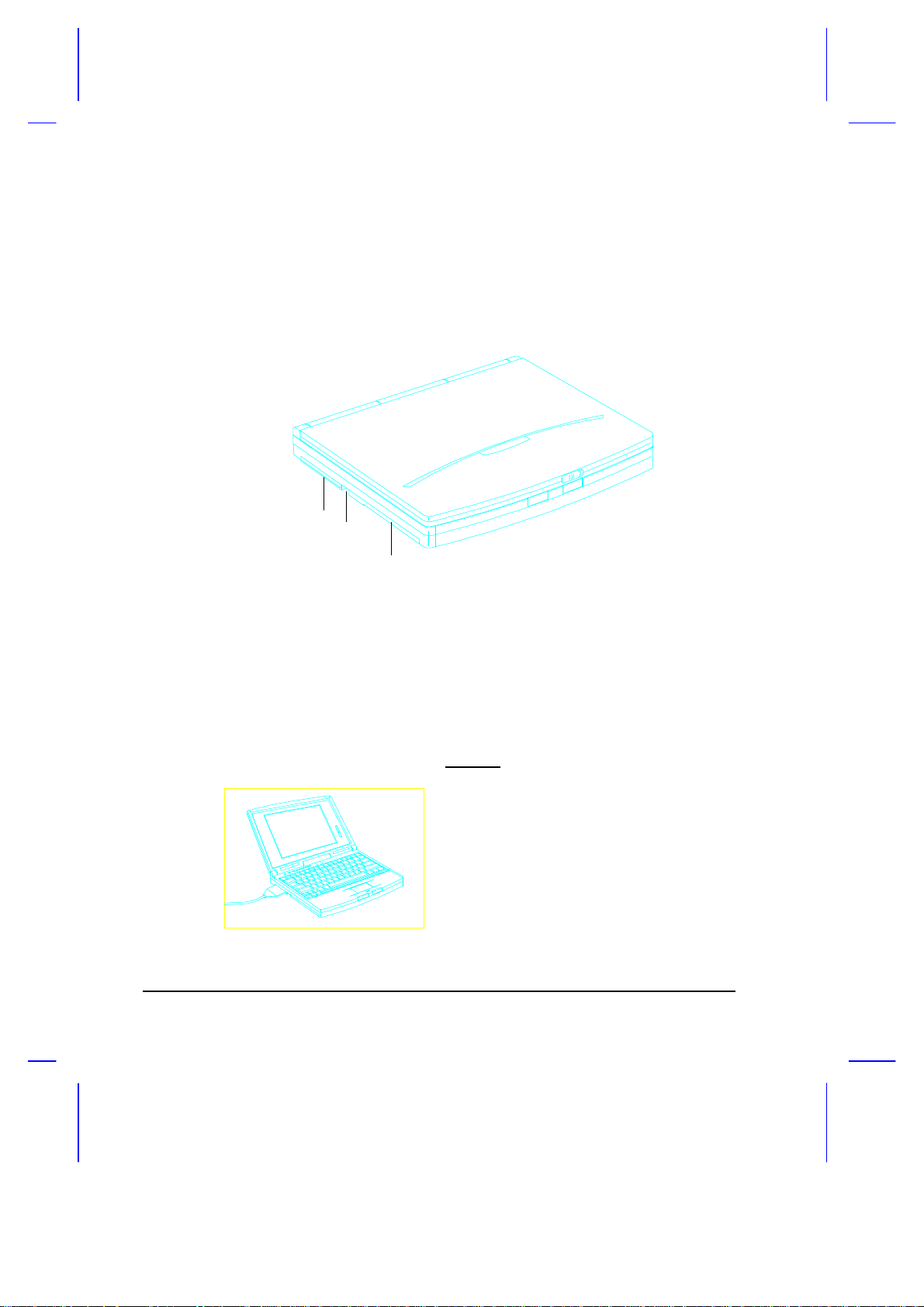
1.6 Right Panel
The battery and accessory bay is located in the right panel. Figure 1-6
shows the right panel.
1 Primary battery compartment
2 Battery cover release latch
3 Accessory bay (with a diskette drive module installed)
Figure 1-6 Right Panel
3
2
1
1-10 User’s Manual
Page 45
Right Panel Features
Primary Battery Compartment
The primary battery compartment houses the primary nickel metal-hydride
(NiMH) battery pack. Follow these steps to install the primary battery pack:
1. Press the battery cover release
latch and slide the cover out.
2. Insert the battery pack into the
primary battery compartment (with
the connector-side up).
3. Replace the battery compartment
cover.
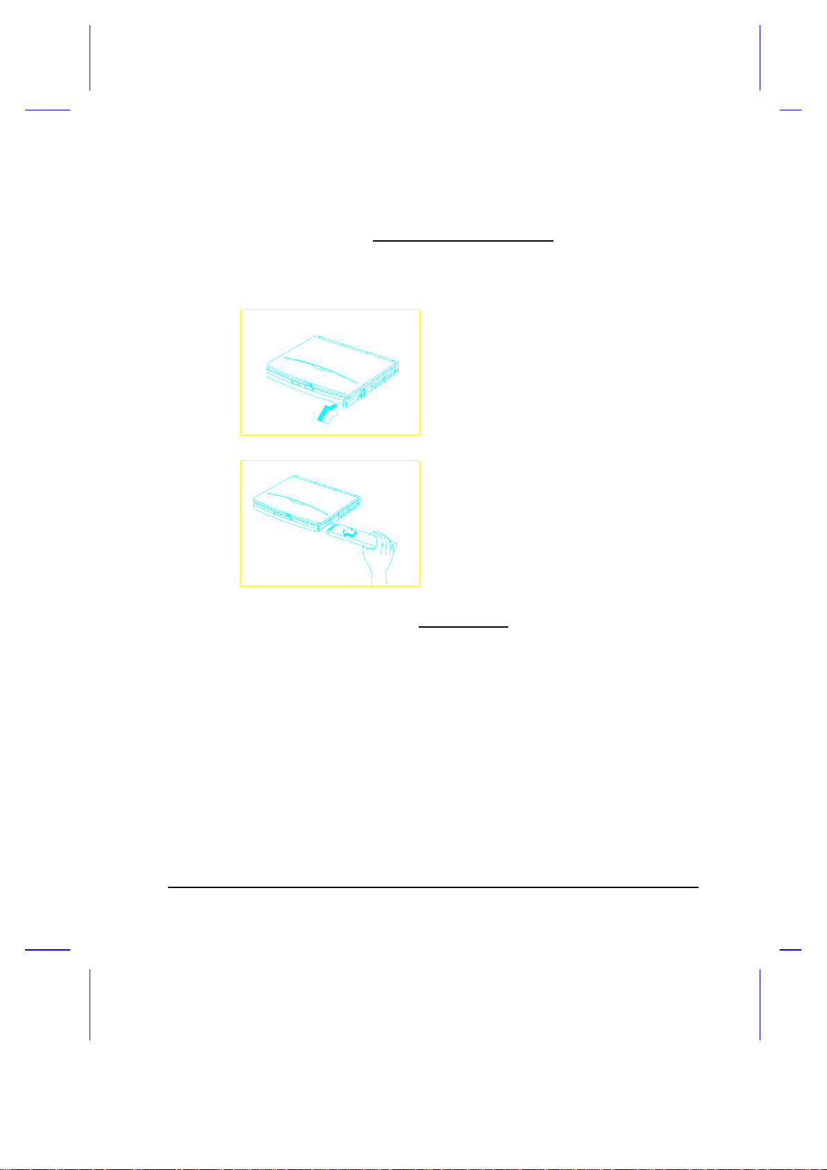
Accessory Bay
The accessory bay accepts three different interchangeable modules:
• Removable 3.5-inch diskette drive module
Removed FDD can be used as an external FDD by connecting it to the
parallel port using the FDD cable.
• Removable PCMCIA slot module (type III slot)
• Secondary battery pack (Lithium-Ion)
Getting Started 1-11
Page 46
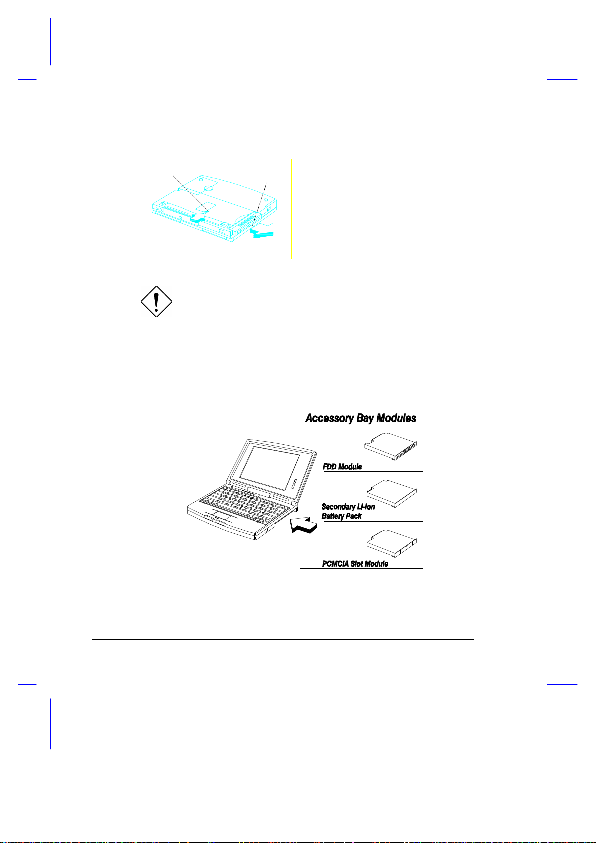
To remove a module:
Module
Bay Lock
Release the accessory bay lock and
pull the module out of the bay.
Turn the power off or go into suspend mode before installing or
removing a module. The system MUST NOT be in standby or
operating mode when you do this.
If the accessory bay houses a diskette drive, the Floppy Disk Drive A
parameter in Setup is automatically set to [1.44 MB 3.5-inch]. It
is automatically set to [None] if the accessory bay houses a PCMCIA slot
module or secondary battery pack.
Figure 1-7 Accessory Bay Modules
1-12 User’s Manual
Page 47
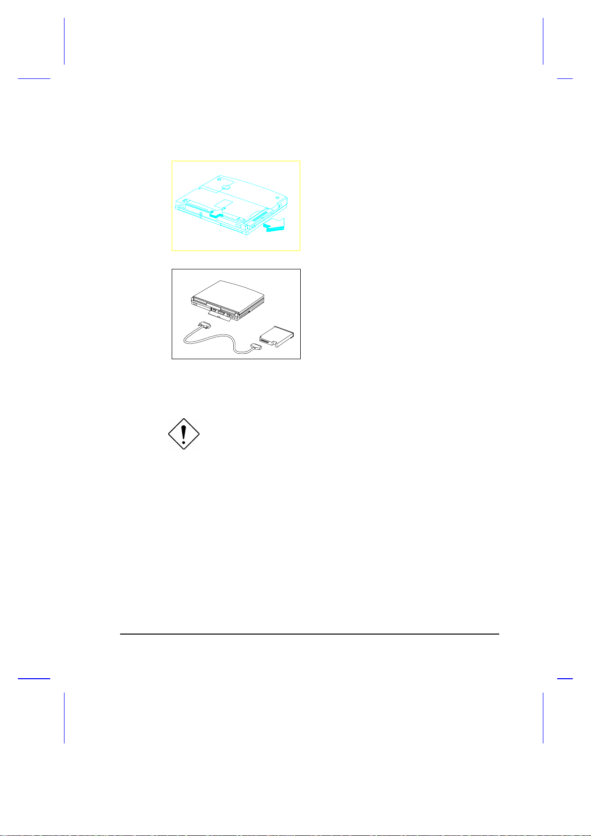
To connect the diskette drive module externally, follow these steps:
1. Remove the diskette drive module
from the accessory bay if one is
installed.
If desired, you may install another
module into the accessory bay.
2. Connect one end (25-pin) of the
FDD cable to the notebook’s
parallel port and the other end to
the diskette drive module.
After system boot-up, the notebook automatically detects the presence of
the diskette drive and makes the proper settings in Setup.
The FDD cable is used exclusively with the diskette drive
module. Do not use it to connect other modules.
Getting Started 1-13
Page 48

1.7 AC Adapter
The AC adapter accepts input voltage ranging from 100V to 240V at a
frequency range of 47Hz to 63Hz. Figure 1-8 shows the AC adapter.
Figure 1-8 AC Adapter
The AC adapter LCD lights up when power is supplied to the AC adapter.
1. Do not use the AC adapter or the battery pack with other
notebooks or any other devices.
2. Do not use other AC adapters and battery packs not
specifically designed for this system.
AC Adapter
Power cord
3. Unplug the AC adapter by pulling on the connector, not the
cord. Pulling on the cord may damage the connections
inside the connector.
1-14 User’s Manual
Page 49

Connecting the AC Adapter
Follow these steps to connect the AC adapter:
1. Plug the power cord into the AC
adapter.
2. Connect the power cord to a power
outlet.
3. Connect the AC adapter to the
notebook.
Getting Started 1-15
Page 50

1.8 Starting the System
Figure 1-9 shows the location of the power on/off switch ( ). Press this
toggle switch to turn the notebook on and off. The power indicator (an LED
found to the left of the power switch) lights up when you turn on the
notebook.
Figure 1-9 Turning On the Power
In some cases, you may need to press harder on the power
switch, the suspend and the setup buttons for the desired effect
to take place.
The notebook runs a series of power-on self-tests (POST) and displays
POST messages. Next, copyright and other messages appear on the
screen followed by the DOS prompt C>. If you get an error message or the
DOS prompt does not appear, see Chapter 6 for assistance.
Avoid turning the notebook on and off in intervals of less than
five seconds between power on and off, as this may damage
your hard disk drive.
1-16 User’s Manual
Page 51

1.9 Interior Features
Figure 1-10 shows the location of the control buttons and status indicators.
Standby/Suspend button
No-reboot Setup button
Power switch
Power indicator
LCD contrast
1
control
Status indicators
Figure 1-10 Control Buttons and Status Indicators
1
The TFT model has no contrast control.
Getting Started 1-17
Page 52

Control Buttons
Power switch This toggles the system power on and off.
No-reboot Setup button This button enables you to access the
Advanced Configuration screens of the Setup utility. This gives you
the option of not rebooting when you exit Setup.
Standby/Suspend button This button enables the notebook to enter
standby or suspend mode. See section 2.4 for details on these
modes.
Contrast control This controls the display clarity of the LCD screen
(STN color models only)
Status Indicators
Power indicator This lights up (green) when power is applied to the
notebook. It flashes when the notebook is in a battery-low condition.
Standby mode indicator This lights up when the system is in
standby mode.
Hard disk drive activity indicator This lights up when the system
accesses the hard disk drive.
Num Lock indicator This lights up when the Num Lock function is
activated.
Caps Lock indicator This lights up when the Caps Lock function is
activated.
Scroll Lock indicator This lights up when the Scroll Lock function is
activated.
1-18 User’s Manual
Page 53

1.10 Keyboard
The keyboard has full-sized keys, including an embedded keypad, separate
cursor keys and twelve function keys.
Figure 1-11 Keyboard — U.S. Keyboard
Figure 1-12 Keyboard — U.K. Version
Getting Started 1-19
Page 54

Lock Keys
The keyboard has three lock keys which you can toggle on and off. When
you activate a lock key, the corresponding LED lights up.
@ When the Caps Lock indicator is on, all
alphabetic characters typed are in uppercase.
[ When the Scroll Lock indicator is on, the screen
moves one line up or down when you press w or
y respectively. Scroll lock does not work with
some applications.
] When the Num Lock indicator is on, the
embedded keypad is in numeric mode. The keys
function as a calculator (complete with arithmetic
operators +, -, *, and /).
Hot Keys
The keyboard also has a number of hot keys or key combinations which
allow you to perform special functions.
b-a-c Warm-Boot hot key This allows you to execute a
warm boot.
b-a-| Setup hot key This allows you to access the
Setup utility.
Setup button ( ) -r Battery discharge hot key This enables the rapid
discharge of the primary battery pack (NiMH)
prior to recharge. The secondary battery pack
(Li-Ion), if installed, is not affected.
1-20 User’s Manual
Page 55

Embedded Keypad
The embedded keypad, which has functions similar to a desktop numeric
keypad, is indicated by smaller characters located in the upper right corner
of the keycaps. To simplify the keyboard legend, the cursor-control key
symbols are not printed on the keys.
Figure 1-13 Embedded Keypad
Table 1-2 tells how to use the embedded keypad.
Table 1-2 Using the Embedded Keypad
Desired Access Num Lock On Num Lock Off
Number keys on
embedded keypad
Cursor-control keys
on embedded keypad
Main keyboard keys Hold while typing letters
Type numbers in a normal
manner.
Hold j while using cursorcontrol keys.
on embedded keypad.
Hold while using
cursor-control keys.
Type the letters in a
normal manner.
Getting Started 1-21
Page 56
Palm Rest and Keyboard Tilt Supports
The palm rest, located below the keyboard, gives you a place to rest your
hands while you type.
Figure 1-14 Palm Rest
In addition, two foot supports on the underside allows you to tilt the
notebook to a more comfortable typing position.
Figure 1-15 Keyboard Tilt Supports
1-22 User’s Manual
Page 57

1.11 Touchpad
The touchpad is a PS/2-type mouse-compatible pointing device that senses
movement on its surface. This means the cursor responds as you move
your finger on the surface of the touchpad. Its central location on the palm
rest enables comfortable use for both left and right-hand users.
Figure 1-16 Touchpad
The touchpad works with most mouse drivers.
If your notebook did not come with pre-loaded software,
remember to install the touchpad driver included in the system
utilities diskette(s). The touchpad driver also supports special
functions that work uniquely with the touchpad. See Appendix
D for details.
Getting Started 1-23
Page 58

Touchpad Basics
The following tips will help you use the touchpad:
1. Move your finger across the touchpad to move the cursor.
2. Press the left and right buttons below the touchpad to do selection and
execution functions. These two buttons are similar to the left and right
buttons on a mouse. Tapping on the touchpad produces similar
results. See Table 1-3.
Table 1-3 Touchpad Functions
Function Button Tap
Execution click twice tap twice
Selection click once tap once
Drag click and hold to drag the
cursor
tap twice and hold to drag the
cursor
Keep your fingers dry and clean when using the touchpad.
Keep your fingers clear of the touchpad when typing.
The touchpad is sensitive to finger movements. Hence, the
lighter the touch, the better the response. Tapping too hard will
not increase the touchpad’s responsiveness.
1-24 User’s Manual
Page 59

1.12 Using the Notebook for the First Time
0V
Zero-Volt
Follow these steps when you use the notebook for the first time, to ensure
top performance right from the start.
1. Install the battery pack into the notebook.
2. Connect the AC adapter. See section 1.7.
3. Power on the notebook and condition the battery pack. See section
2.3.2 for details.
When the battery is charging, the power indicator turns orange. The
power indicator turns off when the battery pack is fully charged.
4. Power on the system when the battery is fully charged. If your
notebook has pre-installed software, go directly to item 6;
otherwise, insert MS-DOS
diskette #1 into the diskette
drive and boot up the system.
Follow the instructions to install
MS-DOS.
You may also want to install Windows if your package includes it.
Insert Windows diskette #1 into the diskette drive and type A:\SETUP.
Follow the screen instructions to install Windows.
5. Install the zero-volt suspend function.
The Zero-Volt (Hibernation)
Suspend-to-Disk function is a
(Hibernation)
Suspend-to-Disk
Getting Started 1-25
power-saving feature that saves
all current status information and
images on your hard disk when
your notebook enters suspend
mode.
Page 60

If you want to use the zero-volt suspend function, you have to create a
partition on the hard disk. Remove the MS-DOS diskette and insert
the system utilities diskette into the diskette drive. Type ASTDK.EXE
in the ASTDK subdirectory to automatically reserve a partition1. Refer
to Appendix D for more details.
If you do not install ASTDK, the notebook can only enter
standby mode and not suspend mode. Standby mode still
consumes power whereas suspend mode consumes none.
Data is also lost when power runs out when the notebook is in
standby mode.
You can also install the other system utilities. See Appendix D for
details.
6. If the notebook displays an error message or if you encounter any
problems, see section 6.2 for corrective actions.
7. You may operate the system on AC or battery power. To conserve
battery power, you can make use of the different power-saving modes
described in sections 2.4.
8. Read through this manual so that you can get the most out of this
powerful notebook PC!
1
For details, refer to the file README.DOC in the ASTDK subdirectory of the system utilities diskette.
Refer also to the 0V suspend utility (ASTDK) information in Appendix D.
1-26 User’s Manual
Page 61
Operating on Battery Power
This chapter contains the information you need to know to operate the
notebook on battery power.
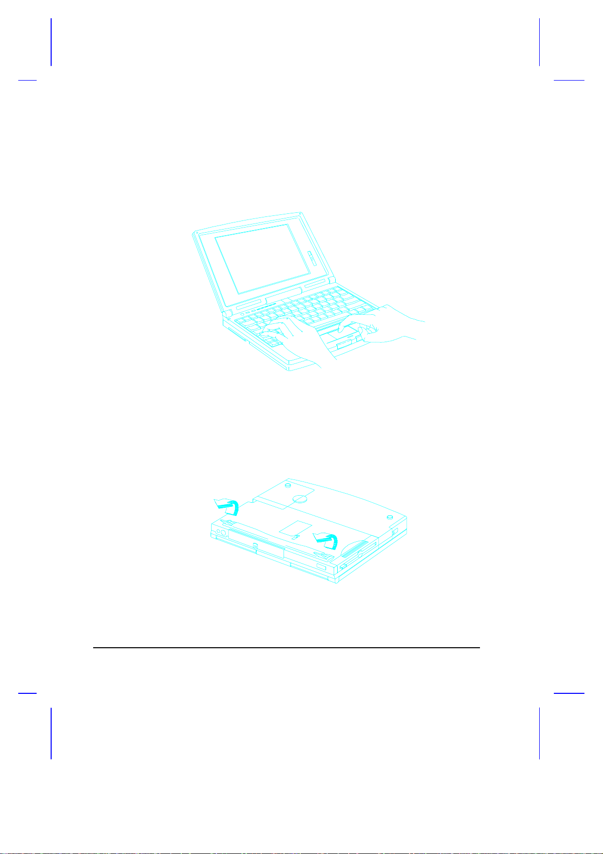
2.1 Battery Pack
Whenever possible, use the AC adapter. The battery will come in handy
when you travel or during a power failure. It is advisable to have an extra
fully-charged battery pack available for backup. The battery pack is
installed in the primary battery compartment. Before removing the battery
pack, make sure the notebook power is off. Follow these steps to remove
the battery.
1. Press the cover release and slide
the cover out.
Chapter 2
2. Flip-out the battery handle.
Operating on Battery Power 2-1
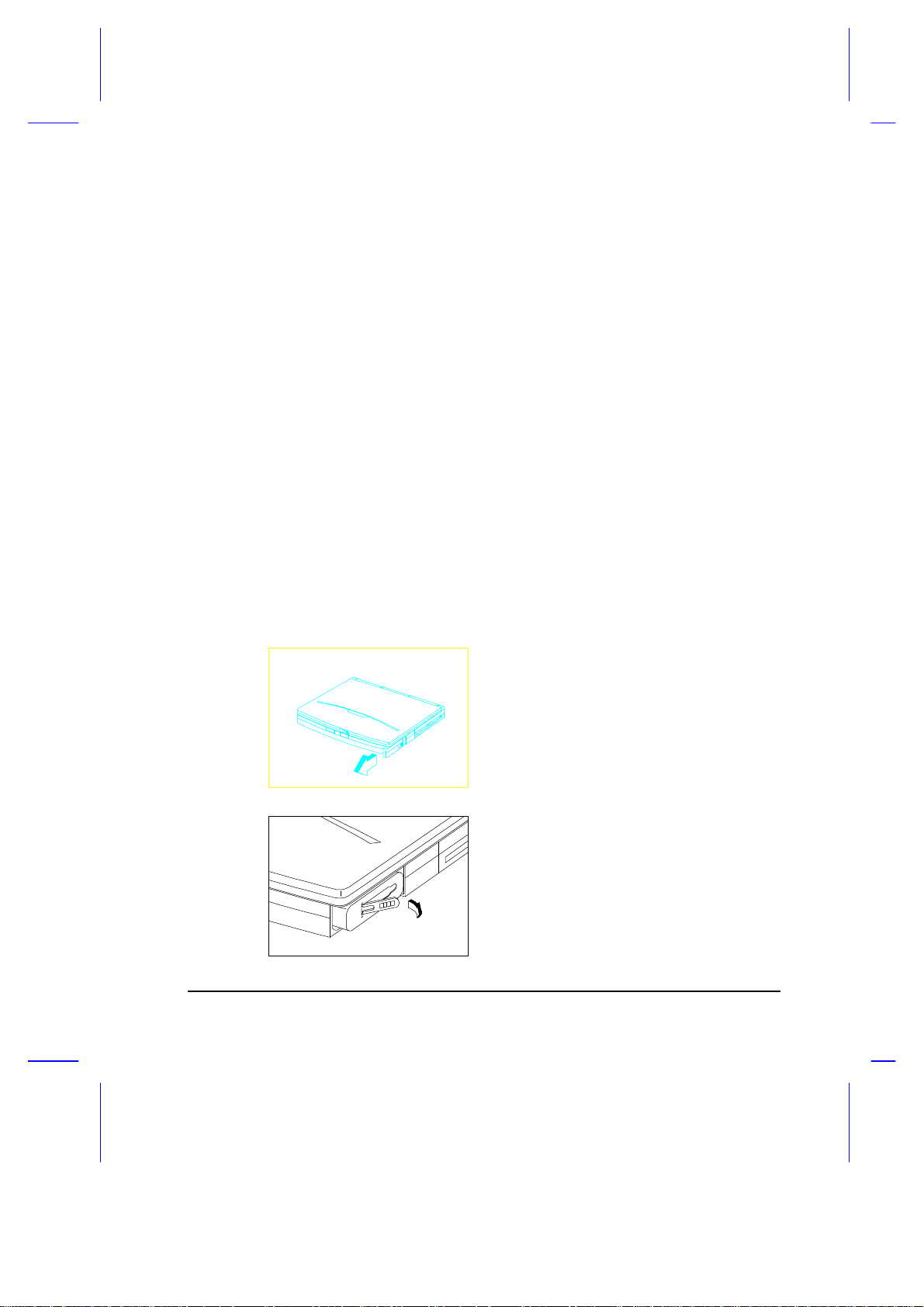
Page 62

3. Using the handle, pull out the battery
Do not expose battery packs to temperatures below 0ºC (32ºF)
or above 60ºC (140ºF). This may adversely affect the battery
pack.
If the notebook is to be stored for more than two weeks, we
suggest that you remove the battery pack. Battery power (from
a fully charged battery pack) depletes in roughly ten days with
the notebook in standby mode. In suspend mode or power-off
condition, the battery power depletes in one month.
2.1.1 Battery Pack Characteristics
pack.
The battery pack has the following characteristics:
• Battery pack self-discharge Battery packs self-discharge slowly, which
may result in a low battery power condition after being stored for
weeks.
• Memory effect This is a phenomenon wherein charging finishes in
one-third the normal charge time. This leaves the battery pack not
fully charged. This situation can usually be improved by conditioning
the battery pack at least twice. Please refer to section 2.3.2 for details
on how to condition the battery pack.
2-2 User’s Manual
Page 63

2.1.2 Installing a Secondary Battery Pack
The notebook’s modular design allows you to use two battery packs at the
same time. The primary battery pack is inserted into the primary battery
compartment. A secondary battery can be inserted into the accessory bay
when you need it.
Follow these steps to install a secondary battery pack.
1. Turn off the power or enter
suspend mode. Then, remove
the internal diskette drive by
unlocking the accessory bay lock
and pulling the diskette drive out.
Set aside.
2. Slide the secondary battery pack
into the accessory bay and click
into place.
3. Power on the notebook or resume
from suspend mode.
Operating on Battery Power 2-3
Page 64

2.2 Charging the Battery
Place the battery pack inside the battery compartment and plug the AC
adapter into the notebook and an electrical outlet.
The adapter has three charging modes:
• Rapid mode
The system uses rapid charging when the notebook (with a battery
pack installed) is turned off and a powered AC adapter is connected to
it. In rapid mode, a fully depleted NiMH battery gets fully charged in
approximately one and a half hours. The power indicator turns orange
in this mode.
• Charge-in-use mode
When the notebook is in use with the AC adapter, the notebook also
charges the battery pack if one is installed. In this mode, the power
indicator displays two colors — green and orange.
• Trickle mode
When the battery is fully charged, the adapter changes to trickle mode
to maintain the battery charge level.
2-4 User’s Manual
Page 65

2.3 Optimizing Battery Life
This section helps you get the most out of battery operation. Optimizing
battery life prolongs the charge/recharge cycle and improves recharge
efficiency.
2.3.1 Maximizing Battery Power
Follow these suggestions to maximize battery power:
• Purchase an extra battery pack
• Use the system utility ASTDK to reserve hard disk space for the zero-
volt suspend function once the system is installed with DOS.
• Condition the battery pack to reduce the possibility of memory effect.
Refer to section 2.3.2.
• Use the AC adapter whenever possible so that the battery is reserved
for on-the-go computing.
• Disable the parallel and serial ports if no devices are connected to
these ports. You can do this through Setup.
• Make use of the power-saving modes described in sections 2.4 and
2.5.
• Eject the PCMCIA card from the card slot when not in use, since the
PCMCIA card draws extra power
When using a network card, logout first before ejecting the card.
• Use the disk cache utility SMARTDRV (bundled with MS-DOS) or
create a virtual disk (RAMDRIVE) to lessen the loading of the hard disk
drive.
• Store the battery pack in a cool, dry place. The recommended storage
temperature for battery packs ranges from 10 to 30 degrees C. The
higher the storage temperature, the faster the battery pack selfdischarges.
Operating on Battery Power 2-5
Page 66

• The batteries can be recharged about 500 times when used as
directed. Excessive rapid recharging decreases battery life.
2.3.2 Conditioning the Battery Pack
Conditioning the battery pack reduces the possibility of memory effect. We
recommend that you condition the battery pack at least once every month,
preferably twice a month. A battery discharge utility helps you discharge
the battery pack quickly.
The secondary battery pack (Li-Ion) does not need
conditioning.
Follow these steps to condition the battery pack:
1. Connect the AC adapter.
2. Turn on the notebook (with the primary battery pack installed).
3. Enter Setup by pressing the no-reboot Setup button ( ) or the
b-a-| key combination.
2-6 User’s Manual
Page 67

Advanced System Configuration
Power Management Mode ---------------------- [Enabled]
LCD Standby Timer ---------------------- [ 1] Minute(s)
Hard Disk Standby Timer ---------------- [ 1] Minute(s)
System Standby/Suspend Timer ----------- [ 3] Minute(s)
Battery-Low Warning Beep ------------------- [Enabled]
Standby/Suspend upon Battery-Low ----------- [Enabled]
Modem Ring Wake Up From Standby ------------ [Enabled]
Password Check during Resume --------------- [Disabled]
Page 1/2
= Move Hightlight Bar, = Change Setting
PgDn/PgUp = Move Screen, F1 = Help, F7 = Discharge Battery, Esc = Exit
→ ←↑ ↓
4. Press r to activate the battery discharge function. This disables all
power-management functions and uses up the battery power even if
the AC adapter is connected. The following screen displays.
System is now powered with an
AC adapter. Please confirm
a battery pack is installed.
Discharge battery now
Enter
Cancel battery discharge
Esc
If the AC adapter is not installed, the following screen displays.
Operating on Battery Power 2-7
Page 68

System is not installed with an AC adapter.
Discharge battery now
Enter
Cancel battery discharge
Esc
Press e to discharge the battery or | to cancel the operation.
The battery pack begins discharging. The battery discharge function also
deactivates the power-saving features by disabling the Power Management
Mode parameter.
After the utility has discharged the battery pack, the notebook power turns
off. The AC adapter then charges the battery pack.
We suggest that you perform this function by activating it at
night before retiring, letting it discharge overnight before
traveling. Also, connect an AC adapter to the notebook and to
a power outlet. This ensures a fully charged battery for use the
next day.
2-8 User’s Manual
Page 69

2.4 Power Management
This notebook has a built-in power management unit that monitors system
activity. System activity refers to any activity involving one or more of the
following devices: keyboard, mouse, diskette drive, hard disk drive,
peripherals connected to the serial and parallel ports, and video memory. If
no activity is detected for a specified period of time (called an inactivity
time-out), the system switches to one of the power-saving modes to
conserve energy. These power-saving modes are LCD standby mode, hard
disk standby, and system standby/suspend mode.
The Setup utility allows you to specify the inactivity time-out.
The power management function does not work when the
cursor is emulated by software such as Chinese system
(ETv3.1), Japanese system (DOSV), Winword, etc.
2.4.1 LCD Standby Mode
Screen activity is determined by the keyboard, the built-in touchpad, and an
external mouse. If these devices are idle for the period specified by the
LCD Standby Timer, the LCD shuts off until you press a key or move the
touchpad or external mouse.
We strongly recommend you to enable the LCD Standby Timer
with a shorter time interval to prolong your battery life.
2.4.2 Hard Disk Standby Mode
The hard disk drive enters the standby mode when there are no disk
read/write operations within the period of time specified by the Hard Disk
Standby Timer. In the standby state, the power supplied to the hard disk
drive is reduced to a minimum. The hard disk drive returns to normal once
the system accesses it.
Operating on Battery Power 2-9
Page 70

2.4.3 System Standby Mode
The notebook consumes very low power in system standby mode. Data
remain intact in the system memory.
The necessary condition for the notebook to enter system standby mode is
that the reserved disk space size for saving system and video memory is
insufficient so the notebook is unable to enter zero-volt suspend mode.
In this situation, there are three ways to enter system standby mode:
• Press the standby/suspend button ( )
• Set a value for the System Standby/Suspend Timer in Setup. If the
waiting time specified by this timer elapses without any system activity,
the notebook goes into system standby mode.
• Enable the Standby/Suspend upon Battery-low parameter in Setup. If
a battery-low condition occurs, the system goes into system standby
mode. See section 2.6.
The following signals indicate that the notebook is in system standby mode:
• The buzzer beeps (when you press the standby/suspend button)
• The standby mode indicator ( ) lights up
When the system enters system standby mode, power is supplied only to
the CPU, DRAM (memory), VGA controller and VRAM (video memory).
Power is cut off to the rest of the system.
Unstored data is lost when you turn off the notebook power in
system standby mode.
To leave system standby mode and return to normal mode, press the
standby/suspend button ( ).
2-10 User’s Manual
Page 71

2.4.4 Suspend Mode
If the notebook is connected to a LAN environment, note that it
does not resume connection even after the notebook returns to
In suspend mode the system power shuts off. The notebook saves all
system information onto the hard disk before it enters suspend mode. The
notebook restores this information and resumes where you left off upon
leaving suspend mode.
A necessary condition for the notebook to enter suspend mode is that the
reserved space for saving system information on the hard disk must be
larger than the combined system and video memory size. Under such
conditions, the system standby/suspend button acts as the suspend button.
See Appendix D for information on the ASTDK utility.
In this situation, there are three ways to enter system suspend mode:
• Press the standby/suspend button ( )
• Set a value for the System Standby/Suspend Timer in Setup. If the
waiting time specified by this time elapses without any system activity,
the system goes into suspend mode
• Enable the Standby/Suspend upon Battery-low parameter in Setup. If
a battery-low condition takes place, the notebook enters suspend mode
in about five minutes. See section 2.6.
When the notebook enters suspend mode, the whole system does not
consume any power except for the standby/suspend activation circuit.
To exit system suspend mode, press the power switch ( ) or the
standby/suspend button ( ).
normal operating mode.
Operating on Battery Power 2-11
Page 72

2.5 Advanced Power Management (APM)
This notebook supports the APM standard designed to further reduce
system power consumption. APM is a power-management approach
defined jointly by Microsoft and Intel. An increasing number of software
supports APM to take advantage of power saving features and allows
greater system availability without degrading performance.
To use the APM feature under the Windows environment, run Windows
Setup and select MS-DOS System with APM as your computer type
in the System Information menu. Refer to the Windows user’s guide for
more information.
You can use the APM feature under the DOS environment by including the
POWER.EXE command in the CONFIG.SYS file. See the MS-DOS
manual for instructions on how to edit the CONFIG.SYS file. For more
information about APM, type the following at the DOS prompt:
HELP POWER.EXE e
If you enable the Power Management Mode parameter in Setup
without installing the APM under DOS or Windows, the system
time and date do not display the correct settings after the
notebook returns to normal operation from system standby or
suspend mode. To update the time and date, reboot the
notebook. Enable APM to avoid this problem.
Advanced Power Management greatly prolongs battery life.
Use APM whenever possible.
2-12 User’s Manual
Page 73

2.6 Battery-low Warning
You never have to worry about battery power as long as you are using the
AC adapter. However, when you operate the notebook on battery power,
pay extra attention to the warning beeps and the power indicator.
The power indicator flashes when the battery power is low. If a secondary
battery pack is installed and the power indicator still flashes, the secondary
battery pack is also running low on power.
The following signals indicate a battery-low condition:
• The buzzer generates four continuous beeps every minute, if you
enabled the Battery-low Warning Beep parameter in Setup
• The power indicator flashes at regular intervals until battery power is
depleted
When you receive a battery-low warning, you have around three minutes1 to
save your work. If you do not connect the AC adapter within this period, the
notebook enters suspend mode if the Standby/Suspend upon Battery-low
parameter in Setup is enabled and the following conditions exist:
• There is enough battery power left to save system information onto the
hard disk.
• The reserved disk space for saving these data is larger than the
combined system and video memory size.
Otherwise, the notebook enters system standby mode.
Connect the AC adapter or insert a charged battery pack into
the notebook as soon as possible. Data is lost when notebook
power is cut off during system standby mode.
1
You may have less than three minutes if your battery is not fully charged.
Operating on Battery Power 2-13
Page 74

Table 2-1 lists the recommended course of action when you encounter a
battery-low condition.
Table 2-1 Course of Action for Battery-low Condition
Situation Recommended Action
AC adapter and power
outlet available
An extra fully-charged
battery pack available
AC adapter or power
outlet not available
1. Connect the AC adapter to the system.
2. Save all necessary files.
3. Resume work.
4. Turn off the system if you wish to recharge the
battery rapidly.
1. Save all necessary files.
2. Exit the application.
3. Turn off the system.
4. Replace the battery pack.
5. Turn on the system and resume work.
1. Save all necessary files.
2. Exit the application.
3. Turn off the system.
2-14 User’s Manual
Page 75

Hardware Options
This chapter tells how to install hardware options such as additional
memory, an external keyboard or keypad, VGA monitor, mouse and printer.
For operating instructions, read the manual included with the accessories.
Always turn off the notebook before you install additional
devices. Also, if devices such as a printer or a monitor use a
separate power source, turn on the devices first before you turn
on the notebook.
3.1 Additional Memory
The system has two memory slots that let you install up to 32 MB of
memory using 4/8/16MB industry-standard DIMMs (dual inline memory
modules). These slots are accessible directly under the keyboard. Simply
unlatch and lift the keyboard, then remove the heat sink to expose the
memory slots.
Chapter 3
Table 3-1 lists the possible memory configurations. Other configurations
are not available.
Table 3-1 Memory Configurations
Slot I Slot II Total Memory
4 MB 0 MB 4 MB
4 MB 4 MB 8 MB
8 MB 0 MB 8 MB
Hardware Options 3-1
Page 76
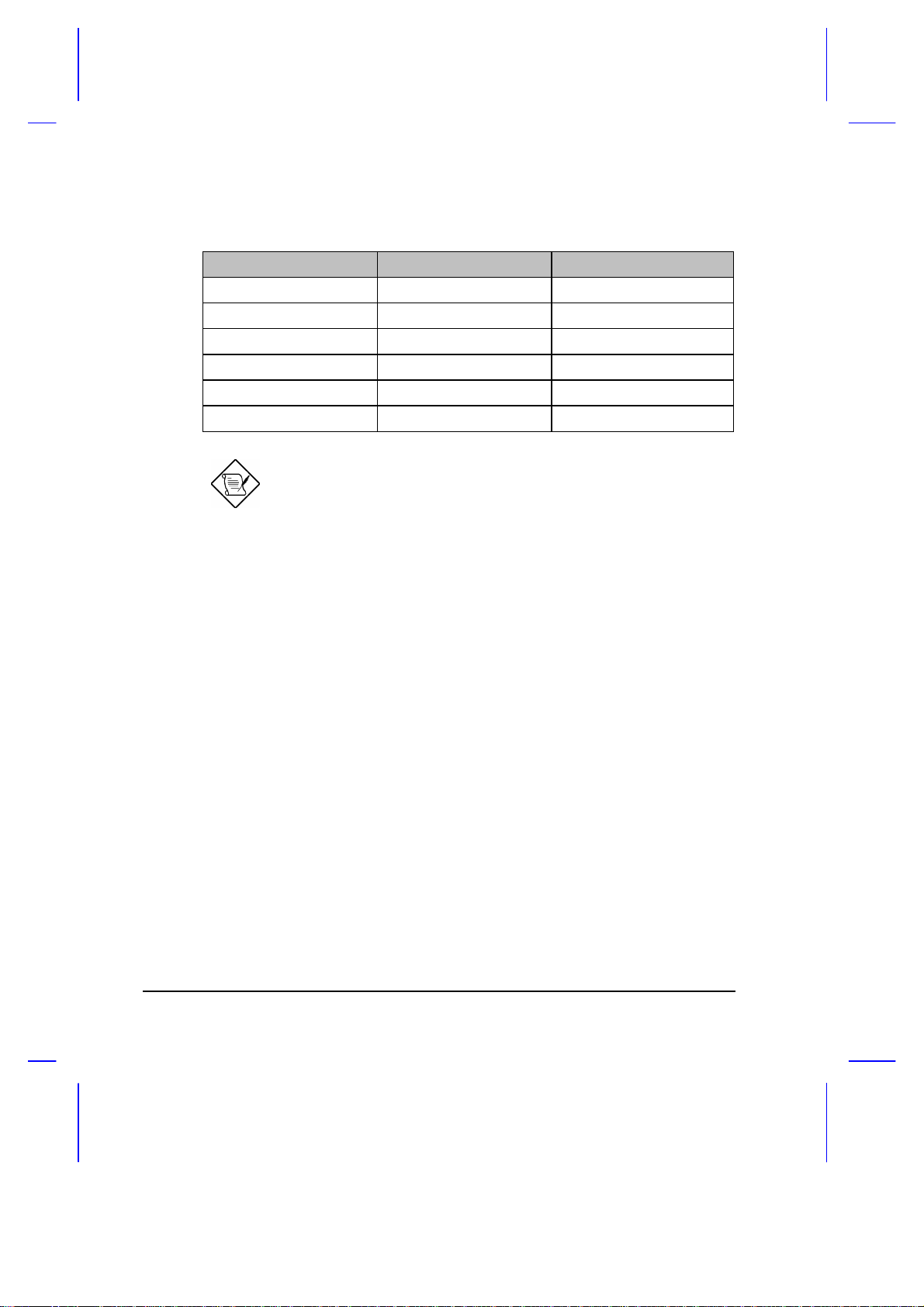
Table 3-1 Memory Configurations
Slot I Slot II Total Memory
8 MB 4 MB 12 MB
8 MB 8 MB 16 MB
16 MB 0 MB 16 MB
16 MB 4 MB 20 MB
16 MB 8 MB 24 MB
16 MB 16 MB 32 MB
The configurations for Slots I and II are interchangeable.
After installing the memory modules, the system automatically detects and
reconfigures the total memory size during the POST routines.
Should you decide to add memory, we recommend that you seek the help
of a qualified service technician. Improper installation may damage the
notebook or cause a malfunction. Consult your authorized dealer for
assistance.
3-2 User’s Manual
Page 77

3.2 Hard Disk Drive Upgrade
This notebook has a modular design that enables easy hard disk drive
upgrades. The storage compartment accepts a high-capacity, 2.5-inch hard
disk drive. See Appendix B for a list of the hard disk drives available.
We recommend that you seek the help of a qualified service technician if
you decide to perform an upgrade. Improper installation may cause a
malfunction or serious damage. Contact your dealer for more information.
Follow these steps to remove the hard disk drive:
1. Power off the notebook. Remove
2. Slide the drive cover as shown in the
the storage compartment cover. Set
aside.
figure and remove it. Set aside.
Then, lift the hard disk drive out of
the compartment and very carefully
disconnect the hard disk drive cable.
Reverse the process to install a hard
disk drive.
The notebook automatically detects the hard disk drive type during poweron self test.
If the hard disk drive capacity is greater than 528MB, enter
Setup and enable the Large Disk Capacity parameter. See
section 4.3.4.
Hardware Options 3-3
Page 78

3.3 External Keyboard or Keypad
This notebook has a keyboard with full-sized keys and an embedded
keypad. If you do a lot of numeric data entry, you may want to use a 17-key
numeric keypad for greater convenience. Also, if you feel more
comfortable using a desktop keyboard, you can install a 101-/102-key,
PS/2-type external keyboard.
Connect an external keyboard or keypad into the keyboard/keypad/mouse
connector ( ) on the rear panel. See Figure 3-1.
Figure 3-1 Connecting an External Keyboard or Keypad
3-4 User’s Manual
Page 79

3.4 External Monitor
To show graphical effects on a larger display, you can connect an external
VGA monitor to the CRT port ( ) on the rear panel. Read the monitor
manual for additional instructions.
Before you install a monitor, turn off the notebook. Always
turn on the external monitor first before you turn on the
notebook.
An external VGA monitor connected to the notebook
automatically displays at 640 x 480 resolution. To display
high-resolution VGA, see the README.DOC file of the VGA
utility found on the system utilities diskette for instructions on
how to install the required software driver. See Appendix D
for details.
3.5 Printer
This notebook supports both serial and parallel printers. For a serial printer,
plug the printer cable into a serial port ( ). For a parallel printer, plug
the printer cable into the parallel port ( ).
Turn on the printer first before you turn on the notebook. See
your printer manual for operating instructions.
If the printer does not function, enter Setup and see to it that
the parallel or serial port is enabled. See section 4.5 for
assistance.
Hardware Options 3-5
Page 80
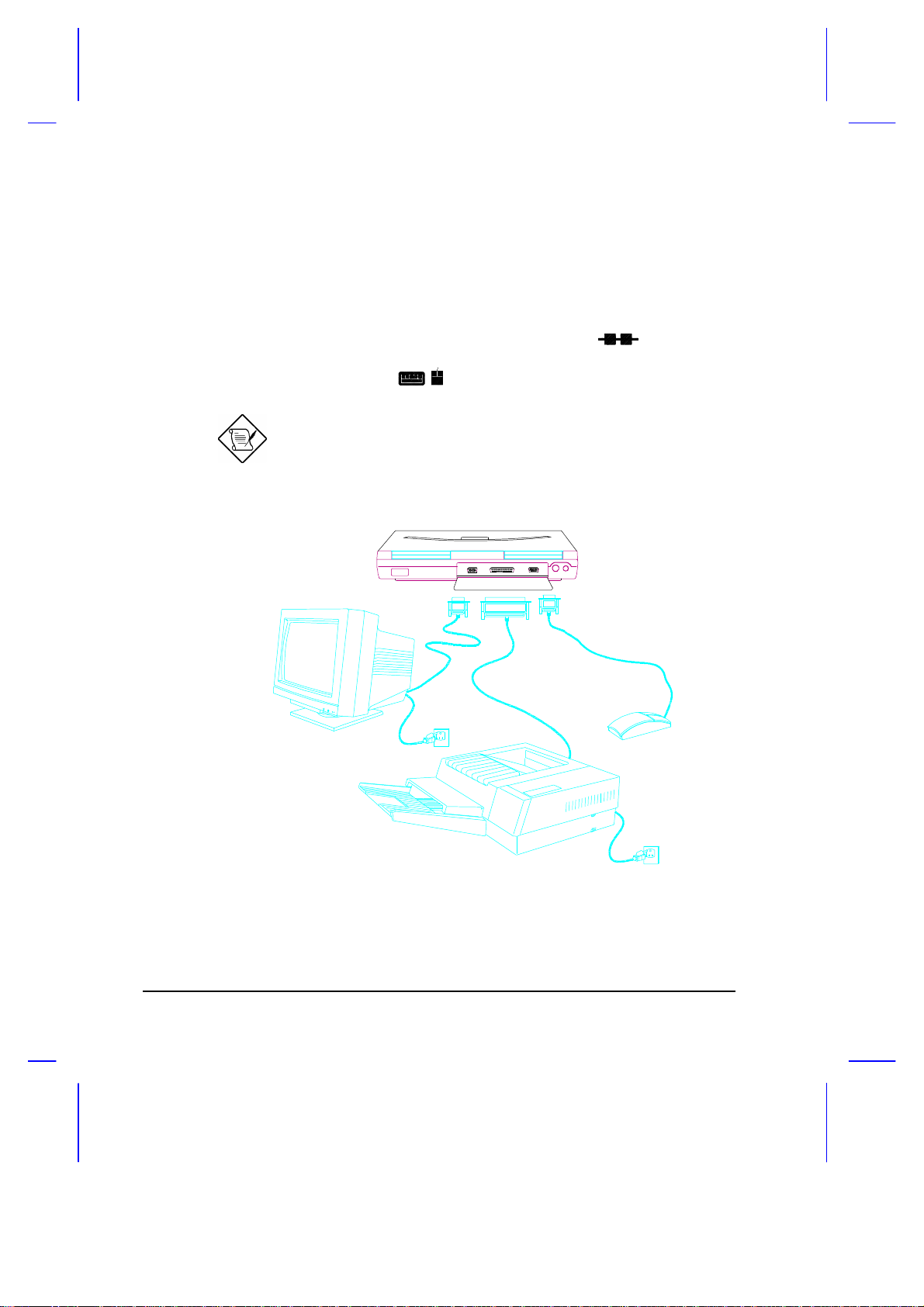
3.6 External Mouse
This notebook accepts either a serial mouse or PS/2-compatible mouse or
similar pointing device. Installing a PS/2 mouse automatically disables the
built-in touchpad.
If you use a serial mouse, plug it into the serial port ( ) on the rear
panel. If you use a PS/2-compatible mouse, plug it into the keyboard/
keypad/mouse connector ( ) on the rear panel.
After you install the mouse, turn on the system. Run a mouse
driver to activate the mouse. Read the mouse manual for
more information.
Figure 3-2 Connecting a Monitor, a Parallel Printer and a Serial Mouse
3-6 User’s Manual
Page 81

3.7 PCMCIA Slot Module
Besides the built-in type II slot found at the left panel, the notebook can
support an additional PCMCIA slot module. The optional module can be
installed into the accessory bay and is interchangeable with the removable
diskette drive or secondary battery pack. The PCMCIA slot module accepts
a type II or type III card (e.g., 1.8-inch ATA hard disk drive).
Follow these steps to install the PCMCIA slot module:
1. Power off the notebook or enter
suspend mode. Unlock the
accessory bay lock and pull out the
diskette drive (or secondary battery
pack). Set aside.
2. Slide in the PCMCIA slot module and
click into place.
After power-on or resume, the notebook automatically sets the Floppy Disk
Drive A parameter to [None].
Hardware Options 3-7
Page 82

Setup
This chapter tells how to use the Setup utility. This utility allows you to
configure the notebook without setting any jumpers or switches.
4.1 When to Use Setup
This notebook is already correctly configured and you do not need to run
Setup. If however, you do receive an Equipment Configuration Error
message after you turn on the notebook, you need to run Setup and make
the necessary modifications. Run the Setup utility if you want to do any of
the following:
• Change the system date and time
• Add or remove a serial mouse or printer
• Enable or disable the memory test, diskette drive, hard disk drive, and
power-saving features
Chapter 4
• Change the system boot drive and display device
• Set the video display features
• Write-protect the hard disk and diskette drive
• Set, change, or remove a system password
• Enable or disable power-saving timers
Setup 4-1
Page 83

4.2 Entering Setup
To enter Setup, you can either press the b-a-| key combination or the noreboot Setup button ( ).
Pressing b-a-| allows you to access the Setup utility and gives you the
option to reboot or to resume from where you left off. If you save any
changes you make, the system reboots to make these changes take effect.
Pressing the no-reboot Setup button ( ) allows you to access the
Advanced System Configuration screens and the system does not reboot
when you exit from Setup. It simply returns you to where you left off before
entering Setup.
After pressing b-a-|, the Setup main menu appears:
BIOS Utility
Basic System Configuration
Advanced System Configuration
System Security
Load Setup Default Settings
↑ ↓ ← → ↵
= Move Highlight Bar, = Select, Esc = Exit and Reboot
Most of the Setup parameters are self-explanatory. Press l if you need
help.
4-2 User’s Manual
Page 84

When you press | to exit a Setup screen, the following prompt appears:
Do you want to save CMOS data?
[Yes] [No]
Select [Yes] to save the changes you made to the configuration values or
[No] to abandon the changes and retain the current values.
Setup 4-3
Page 85

4.3 Basic System Configuration
Basic System Configuration has a one-page screen display illustrated
below. This is accessible only with the b-a-| key combination.
Basic System Configuration
Date ----------------------------- [MM/DD/YY]
Time ----------------------------- [HH:MM:SS]
Floppy Disk Drive A -------------- [1.44 MB 3.5-inch]
Floppy Disk Drive B -------------- [ None ]
Cylinder Head Sector
Hard Disk 0 (130 MB) ------------- [Auto] 980 16 17
Hard Disk 1 ( 0 MB) ------------- [None]
Enhanced IDE Features
Large Hard Disk Capacity ----- [Disabled]
Num Lock After Boot -------------- [Disabled]
Memory Test ---------------------- [Enabled ]
Math Coprocessor ----------------- [Installed]
= Move Hightlight Bar, = Change Setting
F1 = Help, Esc = Exit
→ ←↑ ↓
Page 1/1
Parameters displayed in low brightness are non-user-configurable. The
system detects and sets the values for these parameters.
Use w or y to move from one parameter to another. Use the z or x to
change parameter settings.
You have to change some settings when you add a component to the
notebook.
4-4 User’s Manual
Page 86

4.3.1 Date and Time
The notebook displays the current date in MM/DD/YY format and the
current time in HH:MM:SS format. It uses a 24-hour clock; for example,
6:25 PM displays as 18:25:00.
4.3.2 Floppy Disk Drives
The default setting for Floppy Disk Drive A is [1.44 MB, 3.5-inch].
Since the notebook supports only one diskette drive, Floppy Disk Drive B is
set to [None] and is not user-configurable.
When a diskette drive is externally connected to the notebook’s parallel
port, the notebook automatically detects it after power-on, resume from
suspend, or after a system reboot.
Remember to turn off the notebook power or go into suspend
mode before connecting the diskette drive.
4.3.3 Hard Disk Drives
The default setting for Hard Disk 0 is [Auto]. In this setting, the BIOS
automatically detects your drive parameters. You can also opt to key in
your drive type or drive parameters. See Appendix B for a list of hard disk
drive types. To determine your drive type, compare the data on the label
pasted on your hard disk drive (or supplied in vendor documentation) with
the disk types found in Appendix B. Be sure to select the correct drive type;
otherwise an error message appears when you boot up the notebook. We
suggest you set this parameter to [Auto].
Hard Disk 1 is not supported in this notebook. It is set to [None] and is
not user-configurable.
Setup 4-5
Page 87

4.3.4 Enhanced IDE Features
Set the Large Hard Disk Capacity parameter to [Enabled] if your hard
disk drive capacity is greater than 528 MB.
4.3.5 Num Lock After Boot
When the Num Lock After Boot parameter is set to [Enabled], the
embedded keypad acts as a numeric keypad upon initial power-on or
reboot.
4.3.6 Memory Test
The notebook always tests the main memory for errors each time you turn it
on. Select [Disabled] to bypass the memory test and speed up the
self-test procedure.
4.3.7 Math Coprocessor
This parameter is non-user-configurable and indicates whether the notebook
has a math coprocessor installed or not. This notebook has a built-in
coprocessor.
4-6 User’s Manual
Page 88

4.4 Advanced System Configuration
The Advanced System Configuration section has a two-page screen display
illustrated below. This is accessible with the b-a-| key combination as well
as the no-reboot Setup button ( ).
Advanced System Configuration
Power Management Mode ---------------------- [Enabled]
LCD Standby Timer ---------------------- [ 1] Minute(s)
Hard Disk Standby Timer ---------------- [ 1] Minute(s)
System Standby/Suspend Timer ----------- [ 3] Minute(s)
Battery-Low Warning Beep ------------------- [Enabled]
Standby/Suspend upon Battery-Low ----------- [Enabled]
Modem Ring Wake Up From Standby ------------ [Enabled]
Password Check during Resume --------------- [Disabled]
= Move Hightlight Bar, = Change Setting
PgDn/PgUp = Move Screen, F1 = Help, F7 = Discharge Battery, Esc = Exit
→ ←↑ ↓
Page 1/2
Setup 4-7
Page 89

Advanced System Configuration
Display Device ------------------------- [Auto]
LCD Expand Mode ------------------------ [Enabled]
LCD Text Normal/Reverse Mode ----------- [Normal ]
LCD Graphics Normal/Reverse Mode ------- [Normal ]
LCD Contrast Enhancement --------------- [Disabled]
Page 2/2
= Move Hightlight Bar, = Change Setting
PgDn/PgUp = Move Screen, F1 = Help, Esc = Exit
→ ←↑ ↓
4.4.1 Power Management Mode
With this parameter set to [Enabled], all the timers in Setup take effect
unless specifically disabled by the user. Select [Disabled] to turn off all
the timers.
If APM is installed under DOS or Windows, you cannot disable
the Power Management Mode under Setup. To disable APM,
type Power Off under DOS, or disable the Power icon in the
Windows Control Panel.
4-8 User’s Manual
Page 90

Power Management Timers
• LCD Standby Timer
The notebook shuts off the LCD backlight if there is no activity from the
keyboard or external PS/2 mouse within the period specified by this
timer. To turn the display back on, press a key or move the mouse.
The valid values for this timer range from 1 to 15 minutes. Select
[Off] to disable the timer.
• Hard Disk Standby Timer
The hard disk drive enters standby mode if there are no disk read/write
operations within the period specified by this timer. The hard disk
returns to normal mode once the notebook accesses it.
The valid values for this timer range from 1 to 15 minutes. Select
[Off] to disable the timer.
• System Standby/Suspend Timer
This parameter enables you to set a timeout period for the notebook to
enter either system standby or suspend mode.
If the reserved disk space for saving the screen data is larger than the
combined system and video memory size, the notebook enters
suspend mode. Otherwise, it enters system standby mode.
The valid values for this timer range from 1 to 15 minutes. Select
[Off] to disable the timer.
4.4.2 Battery-low Warning Beep
This parameter allows you to enable or disable the warning beep generated
by the system when a battery-low condition occurs. The default setting is
[Enabled].
4.4.3 Standby/Suspend Upon Battery-low
This parameter enables the system to enter standby/suspend mode when a
battery-low condition takes place. The default setting is [Enabled].
Setup 4-9
Page 91

4.4.4 Modem Ring Wake Up From Standby
If this parameter is set to [Enabled], the notebook wakes up from
standby mode and returns to normal mode when the modem detects a
ringing tone.
4.4.5 Password Checking During Resume
This parameter allows you to prevent unauthorized resumption from the
suspend mode to normal mode. After setting a power-on password, the
notebook automatically sets this parameter to [Enabled]. When you exit
suspend mode and return to normal mode, the notebook requires you to
enter the password.
4.4.6 Display Device
If you install an external VGA display, you can switch display between the
LCD and external display (CRT). This parameter determines which display
device the notebook uses. Table 4-1 describes the different settings.
Table 4-1 Display Device Parameter Settings
Setting Description
Auto
(default)
LCD The notebook uses the LCD even if an external display is present.
Both
1
This setting has no effect for SVGA models. When set to [Both], the display device is still the LCD.
If an external display is present, the notebook uses the external
display; otherwise, the LCD is the display device.
1
The notebook uses the external display and LCD simultaneously.
4-10 User’s Manual
Page 92

4.4.7 LCD Expand Mode
If the LCD Expand Mode is enabled, the VGA subsystem paints in a few
extra lines so that an output less than 640x480 resolution can fill up the
entire LCD screen. The expanded mode gives a better and more balanced
display.
If the parameter is set to [Both], the LCD screen display is automatically
expanded regardless of the parameter value.
Expanded display may not work in some applications.
When the expanded mode is disabled, the screen slides slowly
from top to middle.
4.4.8 LCD Text Normal/Reverse Mode
This parameter is valid for monochrome displays only. It determines
whether the text displayed on the LCD is in normal or reverse mode.
Normal mode displays white characters on a black background and
consumes less power.
4.4.9 LCD Graphics Normal/Reverse Mode
This parameter is valid for monochrome displays only. It determines
whether graphics displayed on the LCD is in normal or reverse mode.
Normal mode displays graphics on a black background and consumes less
power.
4.4.10 LCD Contrast Enhancement
This parameter is valid for monochrome displays only. It allows you to
obtain a sharp contrast on the LCD when enabled. This is achieved by
reducing the number of gray shades displayed.
Setup 4-11
Page 93

Having this parameter enabled may not be appropriate for some
applications due to the reduced gray shades used. For example, a highlight
bar may have the same gray shade as the information it highlights.
4-12 User’s Manual
Page 94

4.5 System Security
System Security
Disk Drive Control
Diskette Drive -------------------- [Normal ]
Hard Disk Drive ------------------- [Normal ]
System Boot Drive ----------------- [Auto]
On Board Communication Ports
Serial Port 1 Base Address -------- [ 3F8 ]
Serial Infrared Base Address ------ [ 2F8 ]
Parallel Port Base Address -------- [ 378 ]
Operation Mode ---------------- [ Standard Parallel Port(SPP) ]
Setup Password ----------------------- [ None ]
Power On Password -------------------- [ None ]
= Move Hightlight Bar, = Change Setting
F1 = Help, Esc = Exit
→ ←↑ ↓
Page 1/1
Setup 4-13
Page 95

4.5.1 Diskette Drive Control
This parameter allows you to enable or disable the read/write functions of
the diskette drive. The following table summarizes the available options.
Table 4-2 Diskette Drive Control Settings
Setting Description
Normal (default) Diskette drive functions normally
Write Protect
All Sectors
Write Protect
Boot Sector
Disabled Disables the diskette drive read/write functions
Disables any diskette drive write function. This option is for
operating systems that access the diskette drive 100 percent
via BIOS only.
Disables the diskette drive write function on a diskette’s boot
sector. This option is for operating systems that access the
diskette drive 100 percent via BIOS only.
4.5.2 Hard Disk Drive Control
This parameter allows you to enable or disable the read/write functions of
the hard disk drive. The following table summarizes the available options.
Table 4-3 Hard Disk Drive Control Settings
Setting Description
Normal (default) Hard disk drive functions normally
Write Protect
All Sectors
Write Protect
Boot Sector
Disabled Disables the hard disk drive read/write functions
Disables any hard disk drive write function. This option is for
operating systems that access the hard disk drive 100
percent via BIOS only.
Disables the hard disk drive write function on the hard disk’s
boot sector. This option is for operating systems that access
the hard disk drive 100 percent via BIOS only.
4-14 User’s Manual
Page 96

4.5.3 System Boot Drive Control
This parameter determines which drive the notebook boots from when you
turn it on. The following table lists the three possible settings.
Table 4-4 System Boot Drive Control Settings
Setting Description
Auto (default) Notebook boots from diskette drive A. If there is no system disk
in drive A, the notebook boots from hard disk drive C. If the hard
disk is a non-system disk, an error message appears.
Drive A Notebook boots from diskette drive A. If drive A does not have a
system disk, an error message appears.
Drive C Notebook boots from hard disk drive C. If the hard disk is a non-
system disk, an error message appears.
4.5.4 Serial Port 1 Base Address
The serial port can accomodate a modem, serial mouse, serial printer, or
other serial devices. The default setting for the serial port 1 address is
[3F8]
1
.
Make sure the serial port base address does not conflict with the address
used by a PCMCIA card, if one is installed.
To save power, disable the serial port when not in use.
4.5.5 Serial Infrared Base Address
The serial infrared port allows you to do wireless data transfer with other
“SIR-aware” systems. The default setting for the SIR port address is
[2F8].
1
The parameter value is the base address expressed in hexadecimal.
Setup 4-15
Page 97

4.5.6 Parallel Port Base Address
The parallel port can accomodate a parallel printer or other parallel devices.
The default setting for the parallel port base address is [378]. The other
options for this parameter are:
• 278
• 3BC
• Disabled
When a diskette drive is externally connected to the notebook’s parallel
port, the notebook automatically detects it.
Remember to turn off the notebook power before connecting
the diskette drive.
To save power, disable the parallel port when not in use.
4.5.7 Parallel Port Operation Mode
The parallel port supports four operation modes:
• Standard Parallel Port(SPP)
• Standard and Bi-directional
• Enhanced Parallel Port(EPP)
EPP means Enhanced Parallel Port. EPP is a parallel port interface that
greatly improves performance for bidirectional block-mode data transfers.
Burst data transfer rates of 50~150 KB/sec. for standard parallel ports jump
to 2 MB/sec. for EPP.
The default setting is [Standard Parallel Port(SPP)].
4-16 User’s Manual
Page 98

4.5.8 Passwords
Two passwords are implemented in this notebook. The Setup Password
prevents unauthorized access to the Setup utility, while the Power On
Password prevents unauthorized access to the notebook. To set a
password, select the desired password (Setup and Power On) to set or edit,
and press z or x. The password prompt (a key) appears:
A message below the menu prompts you to enter a password. The
password may consist of up to seven characters which do not appear on the
screen when you type them. After typing your password, press Enter.
Another prompt appears asking you to retype your password to verify your
first entry.
After setting a password, the notebook sets this parameter to [Present].
The next time you boot the notebook, resume from suspend mode or run
the Setup utility, the password prompt appears. Key in the appropriate
password (Power On or Setup). If the password you entered is incorrect, an
“X” appears. You have three chances to type in the correct password. After
three tries, the following message appears:
Incorrect password specified. System disabled.
The notebook freezes up and disables all devices. You must turn off the
notebook and turn it on again to retry. If you forget your password, you
must reset the configuration values stored in CMOS to defaults. Resetting
CMOS requires opening up the system unit, so contact your dealer for
assistance.
Setup 4-17
Page 99
Removing and Changing Passwords
You can remove or change the password by modifying the desired
password parameter (Power On or Setup) in the Setup utility. If you are
using a U.S. keyboard, you can also remove or change the password during
system startup. To remove the password during system startup, add a
slash after entering the password. For example, if your password is WXYZ,
type the following to remove the password from your system:
WXYZ/
To change the password, add a slash followed by the new password.
WXYZ/ABCD
4-18 User’s Manual
Page 100

4.6 Load Setup Default Settings
Selecting this option allows you to load all the default settings. The default
settings are the values initially stored in CMOS RAM intended to provide
high performance. If in the future, you change these settings, you can load
the default settings again by selecting this option.
When you select this option, the following prompt appears:
Load Setup Default Settings
Are you sure?
[Yes] [No]
Select [Yes] to load the default settings or [No] to abort the operation.
Setup 4-19
 Loading...