


& K DSWHU
System Board
The V55LA-2 is a high-performance system board with a 64-bit
architecture. It supports the Intel P54C and P55C CPUs running at
75/90/100/120/133/150/166/200 MHz. It also supports Cyrix M1/M2
and AMD K5/K6 CPUs. The system board utilizes the Peripheral
Component Interconnect (PCI) local bus architecture that maximizes
the system performance by enabling high-speed peripherals to matc h
the speed of the microprocessor with its 120 MB or 132 MB per
second transfer rate in burst mode.
The board incorporates a Sound Blaster Pro-compatible audio
subsystem that consists of CD-audio, WaveTable, and fax/modem
line-in interfaces.
A standard 1-MB video DRAM comes onboard and is upgradable up to
2 MB. T wo DRAM banks compos ed of four 72-pin s ockets com e with
the board to support single- and double-density SIMMs for a m aximum
system memory of 128 MB. The SIMM sockets accommodate both
the standard page mode and extended data output (EDO) type
SIMMs. The board supports 256-KB or 512- KB pipeline burst sec ondlevel cache.
The system board includes a 188-pin connector f or the slot board that
contains the PCI and ISA bus slots. The two onboard PCI- enhanced
IDE interfaces with a zero-wait state and 16.6 MB per second trans fer
rate support up to four IDE devices. Onboar d I/O interfaces c omprise
of two UART 16550 serial ports, a parallel port with ECP/EPP feature,
and PS/2 keyboard and mouse ports.
System Board 1-1

1.1 Major Features
The system board has the following major features:
A zero-insertion force (ZIF) sock et f or Intel P54C and P55C, Cyrix
•
M1/M2, or AMD K5/K6
Two DRAM banks composed of four 72-pin SIMM sockets that
•
support 4/8/16/32-MB 60/70ns SIMMs
256-KB or 512-KB write-back pipeline burst second-level cache
•
(manufacturing option)
256-KB boot block mode Flash ROM for system BIOS, VGA
•
BIOS, and PnP ESCD
Two PCI-enhanced IDE interfaces that support up to four IDE
•
devices
System clock/calendar with 256-byte CMOS RAM
•
Interfaces for CD-audio, fax/voice modem, and WaveTable
•
support
Standard 1-MB video DRAM onboard plus two upgrade sock ets
•
for up to 2-MB video memory
188-pin connector for PCI/ISA slot board
•
Feature socket for multimedia or Ethernet solution
•
External ports:
•
PS/2 keyboard and mouse ports
•
Two buffered high-speed serial ports
•
One ECP/EPP high-speed parallel port
•
Video port
•
1-2 User’s Guide
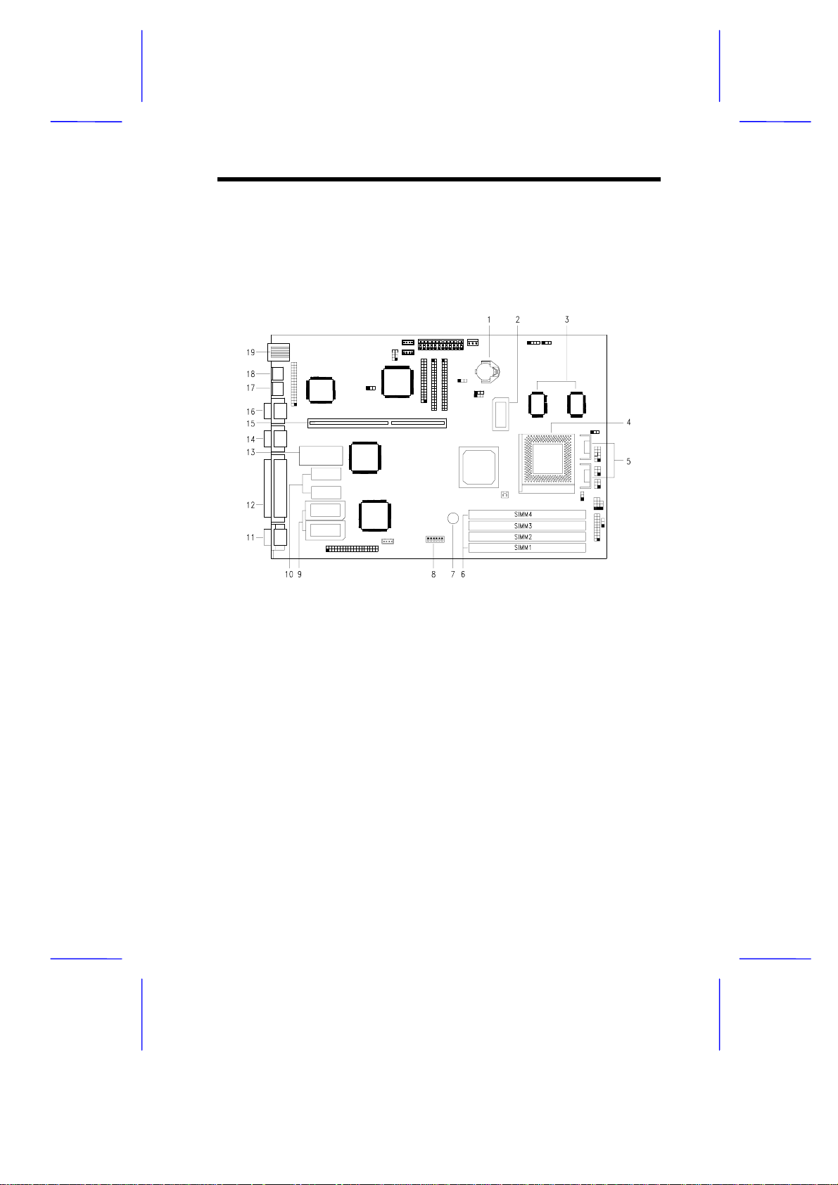
1.1.1 System Board
Figure 1-1 shows the locations of the system board major
components.
1 Battery
2 Tag SRAM
3 Pipeline burst second-level cache
4 Pentium CPU socket
5 CPU voltage regulators
6 SIMM sockets
7 Buzzer
8 Switch 2 (SW2)
9 Video RAM upgrade sockets
10 Video RAM
11 Video port
12 Parallel port
13 BIOS
14 Serial port 2
15 Slot board connector
16 Serial port 1
17 Mouse port
18 Keyboard port
19 USB connector
Figure 1-1 System Board Layout
System Board 1-3
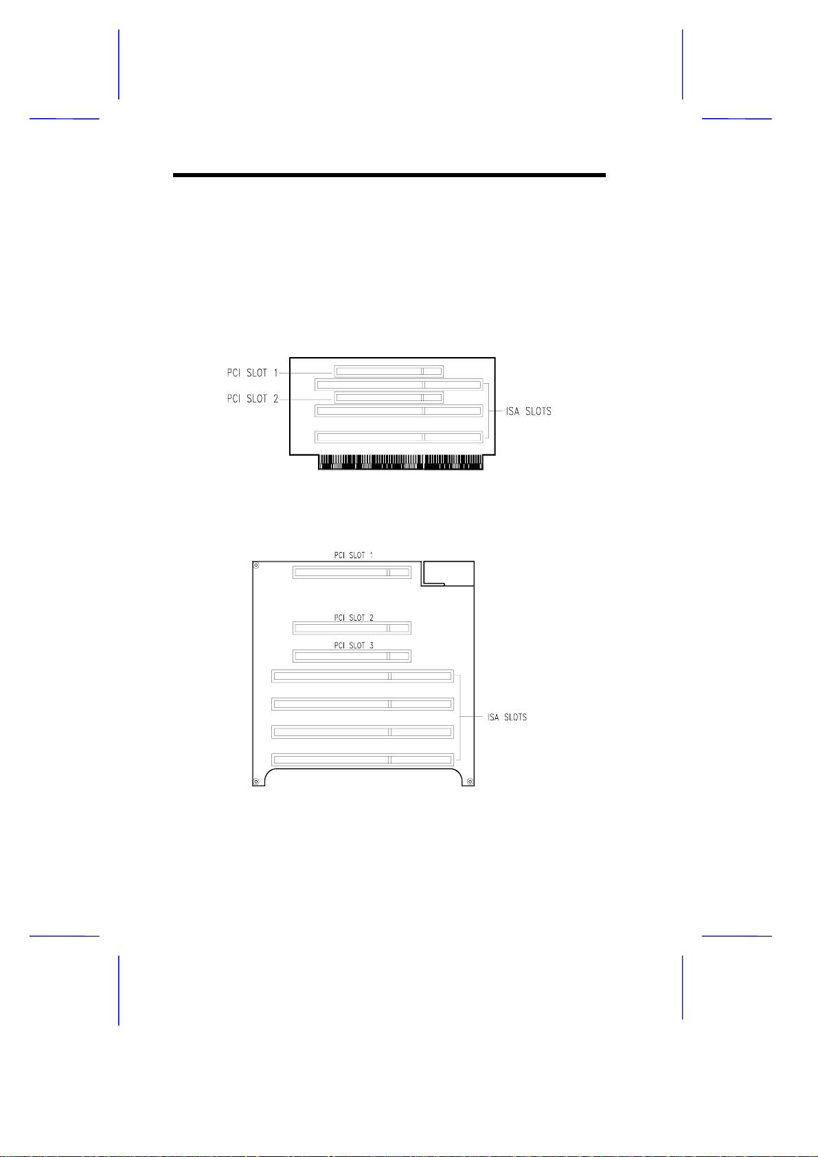
1.1.2 Slot Boards
The system board comes with a slot board already installed. The slot
board carries the PCI and ISA bus slots for system enhanc ements and
future expansion.
The slot board may vary in size and layout depending on your system
housing. Figures 1-2 and 1-3 show the two kinds of slot boards.
Figure 1-2 2 -PCI/3-ISA Slot Board (f or Aspire desktop systems)
Figure 1-3 3-PCI/4-ISA Slot Board
(for Aspire minitower systems)
1-4 User’s Guide
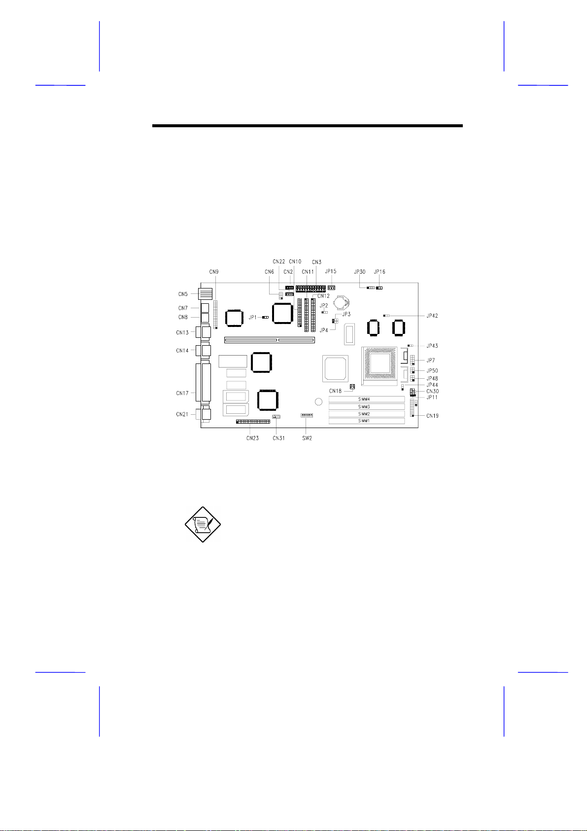
1.2 Jumpers and Connectors
1.2.1 Jumper and Connector Locations
Figure 1-4 shows the jumper and connector locations on the s ystem
board.
Figure 1-4 System Board Jumper and Connector Locations
The blackened pin of a jumper represents
pin 1.
System Board 1-5
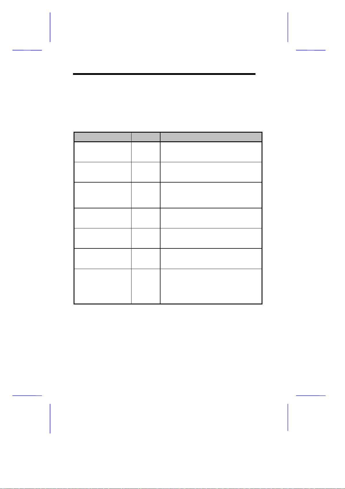
1.2.2 Jumper Settings
Table 1-1 lists the system board jumpers with their corresponding
settings and functions.
Table 1-1 System Board Jumper Settings
Jumper Setting Function
BIOS Type
JP1 1-2
LED Function
JP2 1-2
Second-level Cache
JP3, JP4 1-2, 1-2
Regulator
JP7 Closed
SMM/Reset Switch
JP11 1-2
Software Shutdown
JP16 1-2
CPU Voltage
JP43 (for I/O)
JP44 (for core)
2-3
2-3
1-2, 2-3
2-3, 2-3
Open
2-3
2-3
1-2
2-3
1-2
2-3
For models with Acer BIOS
For models with OEM BIOS
LED for IDE and FDD
LED for IDE only
256 KB
512 KB
1 MB
For single-voltage CPUs (P54C, K5, M1)
For dual-voltage CPUs (P55C, K6, M2)
CN19 pins 19-20 support SMM switch
Reserved
UPS enabled
UPS disabled
3.5V
3.3V
3.2V
2.8V
1-6 User’s Guide
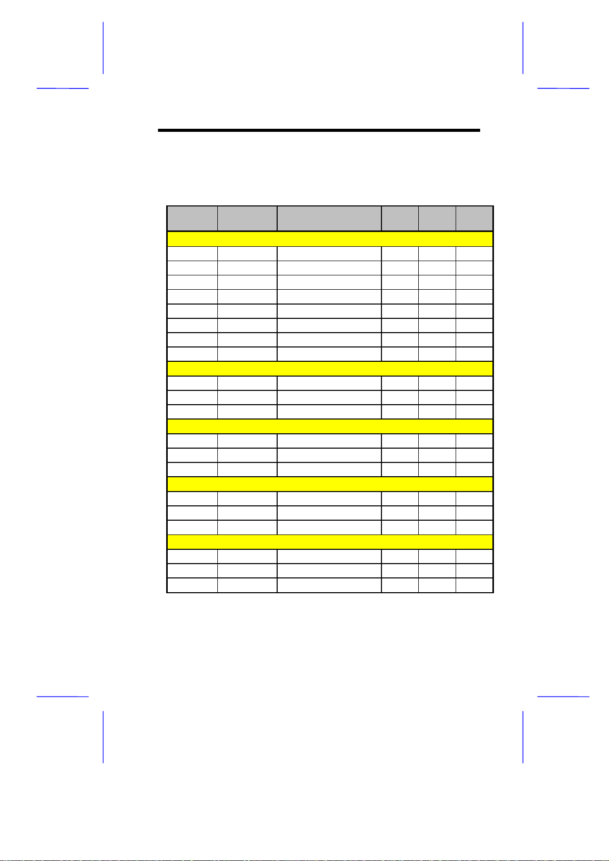
Tables 1-2 to 1-4 show the settings of DIP switch 2 (SW 2), JP7, J P43,
and JP44 for CPU selection.
Table 1-2 SW2, JP7, JP43, and JP44 Settings
CPU Freq.
(MHz)
Intel P54C
P75 50 On On Off Off Closed 2-3 2-3
P90 60 On Off Off Off Closed 2-3 2-3
P100 66 Off On Off Off Closed 2-3 2-3
P120 60 On Off On Off Closed 2-3 2-3
P133 66 Off On On Off Closed 2-3 2-3
P150 60 On Off On On Closed 2-3 2-3
P166 66 Off On On On Closed 2-3 2-3
P200 66 Off On Off On Closed 2-3 2-3
Intel P55C
P150 60 On Off On On Open 2-3 2-3
P166 66 Off On On On Open 2-3 2-3
P200 66 Off On Off On Open 2-3 2-3
Cyrix M1 (6x86)
P120+ 50 On On On Off Closed 2-3 2-3
P150+ 60 On Off On Off Closed 2-3 2-3
P166+ 66 Off On On O f f Closed 2-3 2-3
Cyrix M1 (6x86L)
P120+ 50 On On On Off Open 2-3 2-3
P150+ 60 On Off On Off Open 2-3 2-3
P166+ 66 Off On On O f f Open 2-3 2-3
Cyrix M2
PR166 66 Off On On On Open 2-3 2-3
PR180 60 On Off Off On Open 2-3 2-3
PR200 66 Off On Off On Open 2-3 2-3
Host Bus
Freq. (MHz) SW1 SW2 SW3 SW4
JP7 JP43 JP44
System Board 1-7
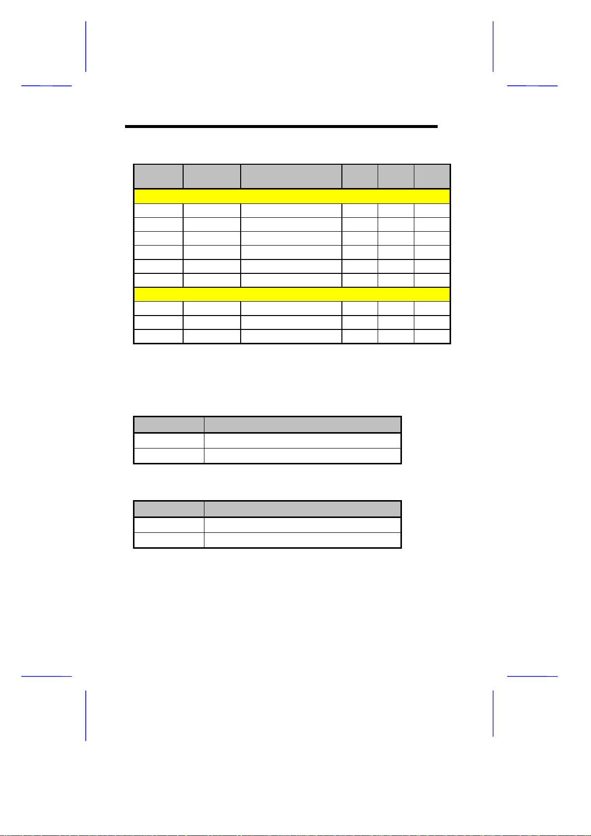
Table 1-2 SW2, JP7, JP43, and JP44 Settings (continued)
CPU Freq.
(MHz)
AMD K5
PR75 50 On On Off Off Closed 1-2 2-3
PR90 60 On Off Off Off Closed 1-2 2-3
PR100 66 Off On Off Off Closed 1-2 2-3
PR120 60 On Off On Off Closed 1-2 2-3
PR133 66 Off On On Off Closed 1-2 2-3
PR166 66 Off On On On Closed 1-2 2-3
AMD K6
PR166 66 Off On On On Open 2-3 1-2
PR200 66 Off On Off On Open 2-3 1-2
PR233 66 Off On Off Off Open 2-3 1-2
Host Bus
Freq. (MHz) SW1 SW2 SW3 SW4
JP7 JP43 JP44
Table 1-3 SW2 Settings (Onboard Sound Chip)
Setting 5 Function
ON Onboard sound chip disabled
OFF Onboard sound chip enabled
Table 1-4 SW2 Settings (Password Security)
Setting 6 Function
ON Password bypass
OFF Password check
1-8 User’s Guide
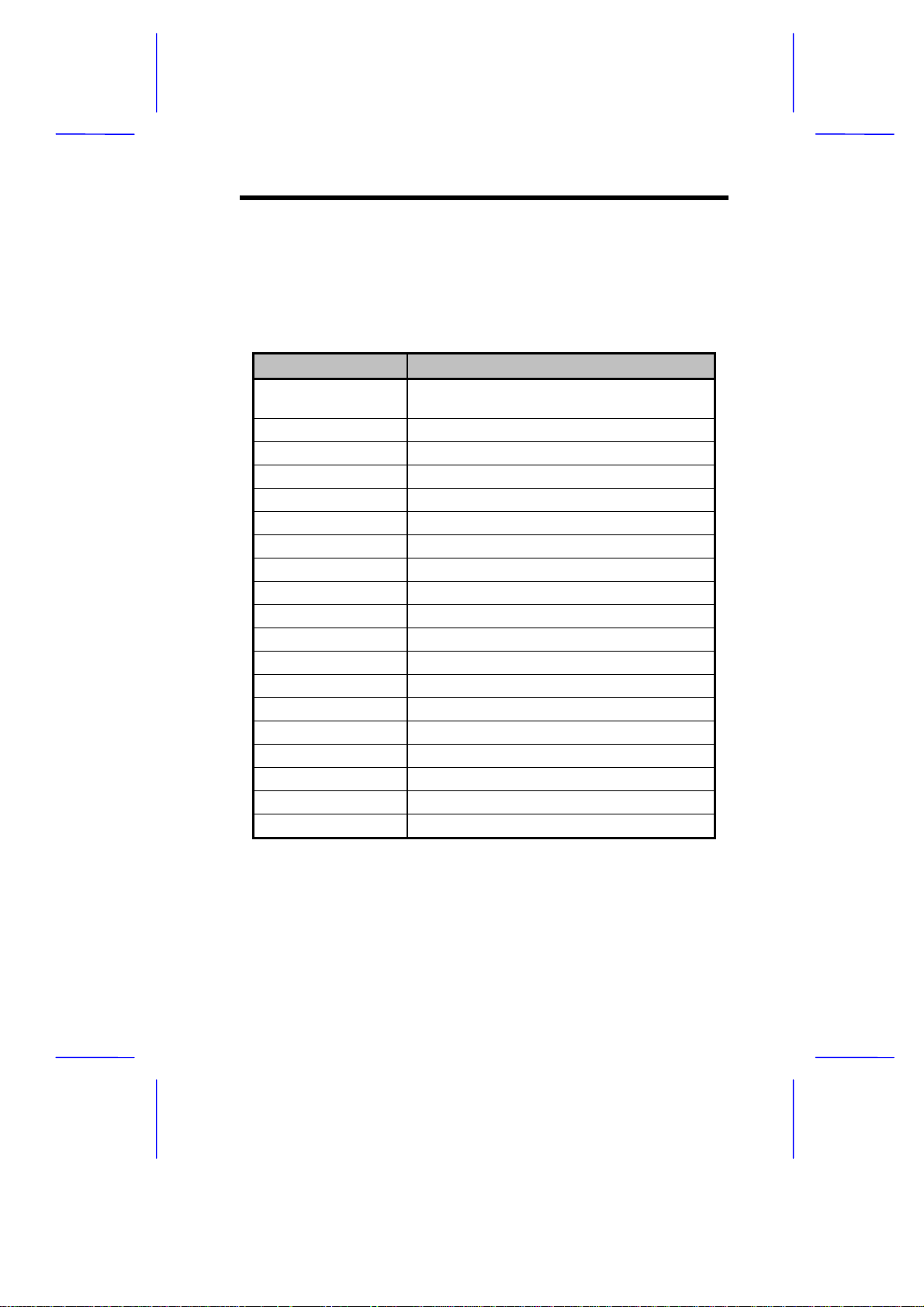
1.2.3 Connector Functions
Table 1-5 lists the differ ent connectors on the system board and their
respective functions.
Table 1-5 Connector Functions
Connector Function
CN1 Feature connector for multimedia or
Ethernet solution
CN2 CD-audio line-in connector
CN3 Power connector
CN5 USB connector
CN6 WaveTable connector
CN7 PS/2 keyboard connector
CN8 PS/2 mouse connector
CN9 Audio I/O board connector
CN10 Diskette drive connector
CN11 IDE connector 2
CN12 IDE connector 1
CN13 Serial port 1
CN14 Serial port 2
CN17 Parallel port
CN18 CPU fan connector
CN19 Multifunction connector
CN21 Video port
CN22 Fax/modem connector
CN23 ATI multimedia connector
System Board 1-9
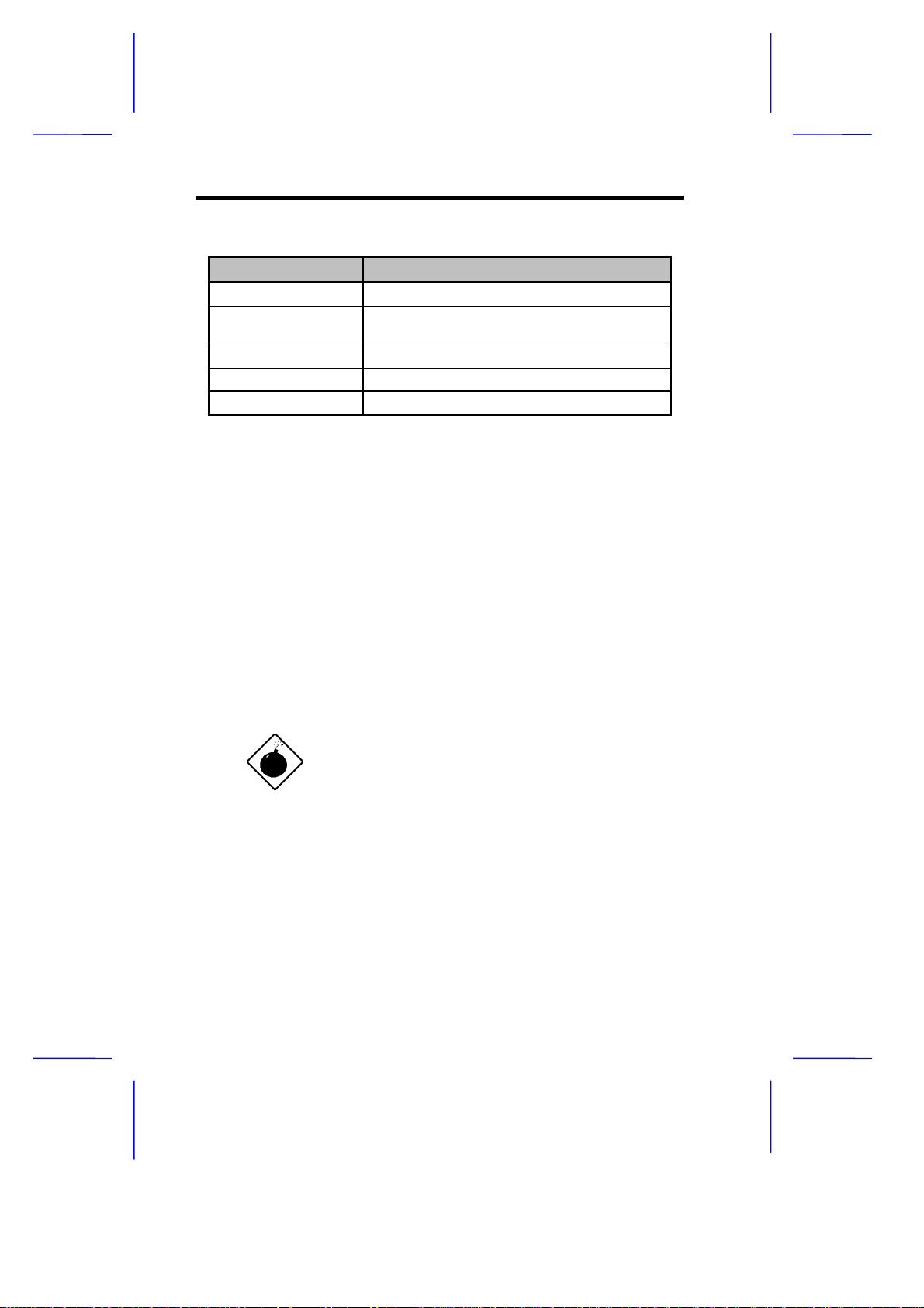
Table 1-5 Connector Functions (continued)
Connector Function
CN31 Internal line-in connector
JP48 Hard disk and message LED (pins 1-3-5)
Power LED (pins 2-4-6)
JP50 Power-on switch connector
JP15 Standby power connector
JP30 External battery connector
See section 1.10.1 for details on power and LED cables to the
connector JP48.
1.3 ESD Precautions
Always observe the following electrostatic discharge (ESD)
precautions before installing a system component:
1. Do not remove a component from its antistatic packaging until
you are ready to install it.
2. Wear a wrist grounding strap before handling electronic
components. Wrist grounding straps are available at most
electronic component stores.
Do not attempt the procedures described in
the following sections unless you are a
qualified technician.
1-10 User’s Guide

1.4 Memory Upgrade
The system board comes with four 72-pin SIMM soc kets that support
4-MB and 16-MB single-density SIMMs and 8-MB and 32-MB doubledensity SIMMs. Table 1-6 lists the possible 64-bit memory
configurations.
Table 1-6 Memory Configurations (64-bit)
Bank 0 Bank 1 Total
SIMM-1 SIMM-2 SIMM-3 SIMM-4 Memory
4 MB 4 MB 8 MB
4 MB 4 MB 8 MB
8 MB 8 MB 16 MB
8 MB 8 MB 16 MB
4 MB 4 MB 4 MB 4 MB 16 MB
4 MB 4 MB 8 MB 8 MB 24 MB
8 MB 8 MB 4 MB 4 MB 24 MB
8 MB 8 MB 8 MB 8 MB 32 MB
16 MB 16 MB 32 MB
16 MB 16 MB 32 MB
4 MB 4 MB 16 MB 16 MB 40 MB
16 MB 16 MB 4 MB 4 MB 40 MB
8 MB 8 MB 16 MB 16 MB 48 MB
16 MB 16 MB 8 MB 8 MB 48 MB
16 MB 16 MB 16 MB 16 MB 64 MB
32 MB 32 MB 64 MB
32 MB 32 MB 64 MB
4 MB 4 MB 32 MB 32 MB 72 MB
32 MB 32 MB 4 MB 4 MB 72 MB
8 MB 8 MB 32 MB 32 MB 80 MB
32 MB 32 MB 8 MB 8 MB 80 MB
16 MB 16 MB 32 MB 32 MB 96 MB
32 MB 32 MB 16 MB 16 MB 96 MB
32 MB 32 MB 32 MB 32 MB 128 MB
System Board 1-11

The system also supports 32-bit m emory configurations . This feature
allows you to install only one SIMM in one configuration. Table 1-7
shows the 32-bit configurations.
Table 1-7 Memory Configurations (32-bit)
Bank 0 Bank 1 Total
SIMM-1 SIMM-2 SIMM-3 SIMM-4 Memory
*
4 MB
4 MB 4 MB 4 MB 12 MB
4 MB 4 MB 8 MB 16 MB
4 MB 4 MB 16 MB 24 MB
4 MB 4 MB 32 MB 40 MB
8 MB* 8 MB
8 MB 8 MB 4 MB 20 MB
8 MB 8 MB 8 MB 24 MB
8 MB 8 MB 16 MB 32 MB
8 MB 8 MB 32 MB 48 MB
16 MB* 16 MB
16 MB 16 MB 4 MB 36 MB
16 MB 16 MB 8 MB 40 MB
16 MB 16 MB 16 MB 48 MB
16 MB 16 MB 32 MB 64 MB
32 MB* 32 MB
32 MB 32 MB 4 MB 68 MB
32 MB 32 MB 8 MB 72 MB
32 MB 32 MB 16 MB 80 MB
32 MB 32 MB 32 MB 96 MB
4 MB
*
May also be installed in SIMM-2, SI MM-3, or SIMM-4.
1-12 User’s Guide

1.4.1 Installing a SIMM
Follow these steps to install a SIMM:
1. Carefully slip a SIMM at a 45° angle into a socket making sure
that the curved edge indicating the pin 1 of the SIMM matches
pin 1 of the socket.
A SIMM fits only in one direction. If you slip
in a SIMM but would not completely fit, you
may have inserted it the wrong way. Reverse
the orientation of the SIMM.
2. Gently push the SIMM to a vertical position until the pegs of the
socket slip into the holes on the SIMM, and the holding clips lock
the SIMM into position. The SIMM should be at a 90° angle when
installed.
1
Pin 1 Indicator
(curved edge)
Figure 1-5 Installing a SIMM
System Board 1-13
2
Peg
Hole

1.4.2 Removing a SIMM
Follow these steps to remove a SIMM:
1. Press the holding clips on both sides of the SIMM outward to
release it.
2. Move the SIMM to a 45° angle.
3. Pull the SIMM out of the socket.
Holding Clip
1
3
2
Figure 1-6 Removing a SIMM
Always remove SIMMs from the socket
labeled SIMM-4, then SIMM-3, and so on.
1-14 User’s Guide

1.4.3 Reconfiguring the System
You must enter Setup after installing or removing SIMMs to
reconfigure the system.
Follow these steps to reconfigure the system:
1. Turn the system on. A memory error message appears,
indicating that the total memory does not match the value stored
in CMOS.
2. Press
appears indicating an incorrect memory configuration.
3. Press
The system boots with the new memory configuration.
+ + to enter Setup. A warning message
twice to exit and reboot the system.
1.5 IDE Hard Disk Support
The system board supports four IDE hard disks, or any other IDE
devices, through the two onboard PCI IDE interfaces. See Figure 1-1
for the location.
Follow the instructions in the housing installation manual on how to
install a hard disk in the system. Connect the c ables according to the
IDE hard disk configuration in Table 1-8.
Table 1-8 IDE Hard Disk Configuration
IDE Connector Master Slave
Channel 1 Hard disk 0 Hard disk 1
Channel 2 Hard disk 2 Hard disk 3
System Board 1-15

1.6 CPU Installation
The system board com es with a zero-insertion for ce ( ZIF) CPU s ock et
for easy installation.
Follow these steps to install a Pentium CPU:
1. Lift up the socket lever.
2. Insert the CPU to the socket. Mak e sure that the notched corner
of the CPU matches the pin 1 indicator on the socket.
Be careful not to bend any pins.
3. Pull down the socket lever.
STEP 1
Notched Corner
STEP 2
STEP 3
Pin 1 Indicator
Figure 1-7 Installing a Pentium CPU
4. Set the CPU jumpers accordingly. Refer to Table 1-2.
1-16 User’s Guide

1.7 Video Memory Upgrade
Larger video memory allows you to display higher resolutions and
more colors. The system board comes with a 1-MB video memory
onboard upgradable to 2 MB.
Follow these steps to upgrade the video memory:
1. Locate the video DRAM upgrade sockets labeled U39 and U40
on the system board. See Figure 1-1.
2. Gently insert a 256K x 16, 60 ns EDO SOJ) chip into each of the
upgrade sockets.
Make sure that the pin 1 indicator on the chip
matches the notched corner of the socket.
Pin 1 Indicator
Notched Corner
Figure 1-8 Installing a Video Memory Chip
System Board 1-17

1.8 Second-level Cache Configuration
The system board supports either 256-KB or 512-KB pipeline burst
second-level cache. The cache size onboard is a manufacturing
option.
Table 1-9 shows the second-level cache configurations.
Table 1-9 Second-level Cache Configurations
Cache Size Onboard Cache Type
256 KB 32K * 32 (7 ns) x 2
512 KB 64K * 32 (6 ns) x 2
1-18 User’s Guide

1.9 Audio Features
The system board supports Sound Blaster Pro-compatible sound
system. It has four connectors onboard to acc ommodate the audioI/O board, WaveTable, CD-ROM, and fax-voice modem.
You may disable the audio feature in the
BIOS Utility.
Figure 1-9 shows the four audio connectors on the system board.
CN9
1 Audio-I/O board connector (CN9)
2 WaveTable connector (CN6)
3 CD audio connector (CN2)
4 Fax/voice modem connector (CN22)
CN6
Figure 1-9 Audio Connectors Onboard
CN2
CN22
System Board 1-19

1.9.1 Installing the Audio-I/O Board
The connector CN9 on the system board acc ommodates the audio-I/O
board. Figure 1-10 shows how to install the board.
CN9
Figure 1-10 Installing the Audio-I/O Board
1-20 User’s Guide

1.9.2 Audio-I/O Board Features
The audio-I/O board consists of microphone port, line-in port, line-out
port, and MIDI/game port. These ports accommodate the external
audio devices.
Microphone Connector
Microphone Port
Line-in Port
Line-out Port
MIDI/Game Port
Line-in Connector
Figure 1-11 Audio-I/O Board
The internal connectors on the audio-I/O boar d are useful for s ystem
housings with built-in speakers, microphone, amplifier, or auxiliary
devices. With the internal audio c onnectors func tioning exactly as the
external audio ports, you can utilize all the sound features supported
by the system board.
Since external speakers, microphone, and other audio devices give
better sound quality, the external audio ports take higher priority than
the internal connectors. When you attach external audio devices to
the ports, the internal audio devices are automatically disabled.
System Board 1-21

1.9.3 WaveTable Daughterboard (Optional)
The system board supports a WableTable
daughterboard as option. The WaveTable
does not come with the basic system.
The WaveTable daughterboard supports the same external
connectors as the audio-I/O board but comes with enhanced audio
features. It bundles the Crystal chipsets that work together to produce
better sound quality.
Figure 1-12 shows the WaveTable daughterboard layout.
Microphone Port
Line-in Port
Line-out Port
MIDI/Game Port
Figure 1-12 WaveTable Daughterboard
1-22 User’s Guide

The WaveTable has two connectors, CN5 and CN6, located
underside. Match these two connectors with the audio-I/O
connector (CN9) and WaveTable connector (CN6) on the system
board.
Figure 1-13 shows how to install the WaveTable connector.
CN6
CN9
Figure 1-13 Installing the WaveTable Daughterboard
System Board 1-23

1.9.4 Audio-I/O Devices
k
Figure 1-14 shows the various devices that you can connect to the
audio-I/O board.
Joystic
Synthesizer
MIDI Adapter
Speakers
Microphone
Figure 1-14 Audio I/O External Devices
Head phones
Stereo Amplifier
CD Player
1-24 User’s Guide

1.10 QuickStart Power Saving Feature
The system board supports a special power saving feature called
QuickStart mode. QuickStart turns off the hard disk, monitor,
keyboard, and mouse once you press the power switch for less than
four seconds while the system is on.
This feature requires the Power Saving
Operation Mode parameter in the BIOS to be
QuickStart
set to
information on the setting description.
The system board comes with connectors to support the QuickStart
feature. The following sections tell how to connect the power switch
and LED cables, and enter QuickStart mode.
1.10.1 Connecting the Power Switch and
LED Cables
The Aspire housing comes with a special power and LED cables to
connect to the LED board.
Follow these steps to connect the power switch and LED cables.
. See section 2.4 for more
1. Connect the 6-pin power switch connector to JP50 on the LED
board, matching the white cable with pin 1.
2. Connect the 3-pin HDD/MSG LED to pins 1-3-5 of JP48,
matching the green cable with pin 1. See Figure 1-15.
3. Connect the 3-pin power switch LED cable to pins 2-4-6 of JP48
making sure that the green cable matches pin 2. See Figure
1-15.
System Board 1-25

8
e
Power
HDD/MSG
Figure 1-15 Power and HDD/MSG Connector (JP48)
Figure 1-16 shows the locations of JP48 and JP50 on the system
board and which cables to connect to them.
Power LED Cabl
Power Switch Cable
HDD/MSG LED Cable
JP50
JP4
Figure 1-16 Connecting the Power Switch and LED Cables
1-26 User’s Guide

1.10.2 QuickStart Mode Operation
At any time while the system is running, enter the Quick Start mode by
simply pressing the power switch for less the four seconds. This
action causes the system to rest (Q uickStar t state 1) by turning off the
keyboard, mouse, and monitor. After the specified time in the
QuickStart State Timer parameter in BIOS, the system sleeps
(QuickStart state 2) and turns off the hard disk.
Once the system enters Quick Star t mode, the hard disk/mess age LED
and keyboard LED go off, while the power and monitor LEDs start
blinking.
When a mess age comes, the hard disk/message LED star ts blinking
orange, then green when the hard disk reads the message. After
getting the message, the hard disk and the LED go off again.
Press the power switch again for less than f our seconds to return to
the normal mode.
To enter or exit the QuickStart mode, make
sure to press the power switch within four
seconds. Pressing it for more than four
seconds turns off the system.
System Board 1-27

1.11 Installing ISA Cards
Both PnP and non-PnP ISA cards require specific IRQs. When
installing ISA cards, mak e sure that the IRQs required by these c ards
are not previously assigned to PCI devices to avoid resource conflicts.
Follow these steps when installing ISA cards:
1. Remove all PnP cards installed in the system, if any.
2. Enter BIOS utility and set the Reset Resource Assignment
Yes
parameter to
devices. Refer to section 2.6.5.
3. Install non-PnP ISA cards.
4. Turn on the system.
5. Use W indows 95 or ICU to manually assign the appropriate IRQs
to the cards. This ensures that BIOS will not use the resources
assigned to the non-PnP ISA cards.
to clear the resource data assigned to the PnP
BIOS detects and configures only PnP cards.
6. Turn off the system.
7. Install PnP ISA and PCI cards.
8. Turn on the system. This time PnP BIOS automatically
configures the PnP ISA and PCI cards with the remaining free
IRQs.
1-28 User’s Guide

1.12 Error Messages
Do not continue using the computer if you receive an error m es sage of
any type. Note the message and take corrective action. This sec tion
explains the different types of error messages and corresponding
corrective measures.
There are two general types of error messages:
Software
•
System
•
1.12.1 Software Error Messages
Software error messages are returned by your operating system or
application. These messages typically occur after you boot the
operating system or when you run your applications. If you receive
this type of message, consult your application or operating system
manual for help.
1.12.2 System Error Messages
A system error message indicates a pr oblem with the computer itself .
A message of this type normally appears during the power-on self-test,
before the operating system prompt appears.
Table 1-10 lists the system error messages.
System Board 1-29

Table 1-10 System Error Messages
Message Action
CMOS Battery Error Replace the RTC chip or
contact your dealer.
CMOS Checksum Error Check the RTC chip and the
necessary jumper. If the
battery is still good, run Setup.
Display Card Mismatch Run Setup
Diskette Drive Controller Error
or Not Installed
Diskette Drive Error Diskette may be defective. If
Diskette Drive A Type
Mismatch
Diskette Drive B Type
Mismatch
Equipment Configuration Error Modify the memory
Hard disk Controller Error Run Setup.
Hard disk 0 Error Check all cable connections.
Hard disk 1 Error Check all cable connections.
Keyboard Error or No
Keyboard Connected
Keyboard Interface Error Replace the keyboard or
Check and connect the control
cable to the diskette
controller.
not, replace the diskette drive.
Run Setup and select the
proper drive type.
Run Setup and select the
proper drive type.
configuration to agree with
one of the options in Tables
1-6 or 1-7.
Replace hard disk.
Replace hard disk.
Check and connect the
keyboard to the system unit.
contact your dealer.
1-30 User’s Guide

Table 1-10 System Error Messages (continued)
Message Action
Memory Error at:
MMMM:SSSS:OOO
(W:XXXX, R:YYYY)
where:
M: MB, S: Segment,
O: Offset, X/Y: write/read
pattern
CPU Clock Mismatch Run Setup. Check if the CPU
Onboard Serial Port 1
Conflict
Onboard Serial Port 2
Conflict
Onboard Parallel Port Conflict Run Setup and disable the
Pointing Device Error Check and connect pointing
Pointing Device Interface
Error
Press key to continue or
+ + for Setup
Real Time Clock Error Check the RTC chip. If it is still
Check SIMMs on the system
board. Contact your dealer.
clock is correct. If correct, exit
Setup and reboot the system.
If the error message reappears,
ask for technical assistance.
Run Setup and disable the
port.
Run Setup and disable the
port.
port.
device.
Replace the pointing device or
contact your dealer.
Press
to enter Setup.
good, run Setup. If not, replace
the RTC chip.
or + +
System Board 1-31

1.12.3 Correcting Error Conditions
As a general rule, if an error message says "Press F1 to continue," it is
caused by a configuration problem, which can be easily corrected. An
equipment malfunction is more likely to cause a fatal error, i.e., an
error that causes complete system failure.
Here are some corrective measures for error conditions:
1. Run Setup. You must know the correct configuration values for
your system before you enter Setup, which is why you should
write them down when the system is correctly configured. An
incorrect configuration is a major cause of power-on error
messages, especially for a new system.
2. Remove the system unit cover. Check that the jumpers on the
system board and any expansion boards are set correctly.
3. If you cannot access a new disk, it m ay be because your disk is
not properly formatted. Format the disk fir st using the FDISK and
FORMAT commands.
4. Check that all connectors and boards are securely plugged in.
If you go through the corrective steps above and still receive an error
message, the cause may be an equipment malfunction.
If you are sure that your configuration values are correct and your
battery is in good condition, the problem may lie in a damaged or
defective chip.
In both cases, contact an authorized service center for assistance.
1-32 User’s Guide
 Loading...