

Page 1

Aspire One 522
SERVICEGUIDE
Page 2

Revision History
Refer to the table below for the updates made to this service guide.
Date Chapter Updates
Service guide files and updates are available on the ACER/CSD Website. For more
information, go to http://csd.acer.com.tw
without notice.
. The information in this guide is subject to change
Copyright
Copyright © 2010 by Acer Incorporated. All rights reserved. No p art of this publication may be
reproduced, transmitted, transcribed, stored in a retrieval system, or translated into any
language or computer language, in any form or by any means, electronic, mechanical,
magnetic, optical, chemical, manual or otherwise, without the prior written permission of Acer
Incorporated.
Disclaimer
The information in this guide is subject to change without notice.
There are no representations or warranties, either expressed or implied, with respect to the
contents hereof and specifically disclaims any warranties of merchantability or fitness for any
particular purpose. The software described in this manual is sold or licensed “as is”. Should
the programs prove defective following their purc h as e, the bu ye r (n ot the ma n uf ac tur e r,
distributor, or its dealer) assumes the entire cost of all necessary servicing, repair, and any
incidental or consequential damages resulting from any defect in the software.
ii
Page 3

Conventions
WARNING:
!
CAUTION:
!
IMPORTANT:
+
The following conventions are used in this manual:
Indicates a potential for personal injury.
Indicates a potential loss of data or damage to equipment.
Indicates information that is important to know for the proper completion of a
procedure, choice of an option, or completing a task.
The following typographical conventions are used in this document:
Book titles, directory names, file names, path names, and program/process names are shown in
italics.
Example:
the DRS5 User's Guide
/usr/local/bin/fd
the /TPH15spool_M program
Computer output (text that represents information displayed on a computer screen, such as
menus, prompts, responses to input, and error messages) are shown in constant width.
Example:
[01] The server has been stopped
User input (text that represents information entered by a computer user, such as command
names, option letters, and words) are shown in constant width bold.
Variables contained within user input are shown in an gle brackets (< >).
Example:
At the prompt, type run <file name> -m
Keyboard keys are shown in bold italics.
Example:
After entering data, press Enter.
iii
Page 4

General information 0
This service guide provides all technical information relating to the basic configuration for
Acer global product offering. To better fit local market requirements and enhance product
competitiveness, your regional office may have decided to extend the functionality of a
machine (such as add-on cards, modems, or extra memory capabilities). These localized
features are not covered in this generic service guide. In such cases, contact your regional
offices or the responsible personnel/channel to provide further technical details.
When ordering FRU parts:
Check the most up-to-date information available on your regional Web or channel. If, for
whatever reason, a part number change is made, it may not be noted in this printed service
guide.
Acer-authorized Service Providers:
Y our Acer of fice may have a dif ferent p art number code than th ose given in the FRU list in this
service guide. The list provided by your regional Acer office must be used to order FRU parts
for repair and service of customer machines.
iv
Page 5

CHAPTER 1
Hardware Specifications
Features . . . . . . . . . . . . . . . . . . . . . . . . . . . . . . . . . . . . . . . . . . . . 1-5
Operating System. . . . . . . . . . . . . . . . . . . . . . . . . . . . . . . . . . . 1-5
Platform . . . . . . . . . . . . . . . . . . . . . . . . . . . . . . . . . . . . . . . . . .1-5
System Memory . . . . . . . . . . . . . . . . . . . . . . . . . . . . . . . . . . . .1-5
Display. . . . . . . . . . . . . . . . . . . . . . . . . . . . . . . . . . . . . . . . . . . .1-5
Storage Subsystem . . . . . . . . . . . . . . . . . . . . . . . . . . . . . . . . . .1-5
Audio Subsystem . . . . . . . . . . . . . . . . . . . . . . . . . . . . . . . . . . .1-5
Graphics . . . . . . . . . . . . . . . . . . . . . . . . . . . . . . . . . . . . . . . . . .1-6
Privacy Control . . . . . . . . . . . . . . . . . . . . . . . . . . . . . . . . . . . . .1-6
Optical Media Drive (N/A) . . . . . . . . . . . . . . . . . . . . . . . . . . . .1-6
Communication . . . . . . . . . . . . . . . . . . . . . . . . . . . . . . . . . . . .1-6
Dimension and Weight . . . . . . . . . . . . . . . . . . . . . . . . . . . . . . 1-7
Power Adapter and Battery. . . . . . . . . . . . . . . . . . . . . . . . . . .1-7
I/O Ports. . . . . . . . . . . . . . . . . . . . . . . . . . . . . . . . . . . . . . . . . . .1-7
Special Keys and Controls . . . . . . . . . . . . . . . . . . . . . . . . . . . . 1-7
Environment . . . . . . . . . . . . . . . . . . . . . . . . . . . . . . . . . . . . . . .1-8
Warranty . . . . . . . . . . . . . . . . . . . . . . . . . . . . . . . . . . . . . . . . . .1-8
Optional Items . . . . . . . . . . . . . . . . . . . . . . . . . . . . . . . . . . . . .1-8
Software . . . . . . . . . . . . . . . . . . . . . . . . . . . . . . . . . . . . . . . . . .1-9
Notebook Tour. . . . . . . . . . . . . . . . . . . . . . . . . . . . . . . . . . . . . . . 1-10
Top View. . . . . . . . . . . . . . . . . . . . . . . . . . . . . . . . . . . . . . . . . .1-10
Closed Front View . . . . . . . . . . . . . . . . . . . . . . . . . . . . . . . . . .1-12
Rear View . . . . . . . . . . . . . . . . . . . . . . . . . . . . . . . . . . . . . . . . .1-13
Left View. . . . . . . . . . . . . . . . . . . . . . . . . . . . . . . . . . . . . . . . . .1-14
Right View . . . . . . . . . . . . . . . . . . . . . . . . . . . . . . . . . . . . . . . .1-15
Base View . . . . . . . . . . . . . . . . . . . . . . . . . . . . . . . . . . . . . . . . .1-16
Touchpad Basics . . . . . . . . . . . . . . . . . . . . . . . . . . . . . . . . . . . .1-18
Using the Keyboard . . . . . . . . . . . . . . . . . . . . . . . . . . . . . . . . .1-19
Windows Keys. . . . . . . . . . . . . . . . . . . . . . . . . . . . . . . . . . . . . .1-20
Hotkeys . . . . . . . . . . . . . . . . . . . . . . . . . . . . . . . . . . . . . . . . . . .1-21
Using the Communication Key . . . . . . . . . . . . . . . . . . . . . . . .1-23
System Block Diagram . . . . . . . . . . . . . . . . . . . . . . . . . . . . . . .1-24
Specification Tables . . . . . . . . . . . . . . . . . . . . . . . . . . . . . . . . . . . 1-25
Computer specifications . . . . . . . . . . . . . . . . . . . . . . . . . . . . . .1-25
System Board Major Chips . . . . . . . . . . . . . . . . . . . . . . . . . . . .1-26
Processor. . . . . . . . . . . . . . . . . . . . . . . . . . . . . . . . . . . . . . . . . .1-26
Processor Specifications . . . . . . . . . . . . . . . . . . . . . . . . . . . . . .1-26
CPU Fan True Value Table (For Windows mode). . . . . . . . . . .1-27
CPU Fan True Value Table (For DOS mode) . . . . . . . . . . . . . .1-27
System Memory. . . . . . . . . . . . . . . . . . . . . . . . . . . . . . . . . . . . .1-27
Memory Combinations. . . . . . . . . . . . . . . . . . . . . . . . . . . . . . . .1-28
v
Page 6

Video Interface. . . . . . . . . . . . . . . . . . . . . . . . . . . . . . . . . . . . . .1-28
BIOS . . . . . . . . . . . . . . . . . . . . . . . . . . . . . . . . . . . . . . . . . . . . .1-28
LAN Interface. . . . . . . . . . . . . . . . . . . . . . . . . . . . . . . . . . . . . . .1-29
Keyboard . . . . . . . . . . . . . . . . . . . . . . . . . . . . . . . . . . . . . . . . . .1-30
Hard Disk Drive (AVL components). . . . . . . . . . . . . . . . . . . . . .1-31
Super-Multi Drive (not available with this model). . . . . . . . . . . .1-32
LED 10.1”. . . . . . . . . . . . . . . . . . . . . . . . . . . . . . . . . . . . . . . . . .1-33
LCD Inverter (not available with this model) . . . . . . . . . . . . . . .1-33
Display Supported Resolution (LCD Supported Resolution). . .1-34
Graphics Controller . . . . . . . . . . . . . . . . . . . . . . . . . . . . . . . . . .1-34
Display Supported Resolution (GPU Supported Resolution). . .1-34
Bluetooth Interface. . . . . . . . . . . . . . . . . . . . . . . . . . . . . . . . . . .1-34
Bluetooth Module. . . . . . . . . . . . . . . . . . . . . . . . . . . . . . . . . . . .1-35
Camera . . . . . . . . . . . . . . . . . . . . . . . . . . . . . . . . . . . . . . . . . . .1-35
Mini Card . . . . . . . . . . . . . . . . . . . . . . . . . . . . . . . . . . . . . . . . . .1-35
3G Card. . . . . . . . . . . . . . . . . . . . . . . . . . . . . . . . . . . . . . . . . . .1-35
Audio Codec and Amplifier (amplifier not available) . . . . . . . . .1-35
Audio Interface. . . . . . . . . . . . . . . . . . . . . . . . . . . . . . . . . . . . . .1-38
Wireless Module 802.11b/g/n . . . . . . . . . . . . . . . . . . . . . . . . . .1-38
Battery . . . . . . . . . . . . . . . . . . . . . . . . . . . . . . . . . . . . . . . . . . . .1-38
VRAM (not available with this model) . . . . . . . . . . . . . . . . . . . .1-39
USB Port . . . . . . . . . . . . . . . . . . . . . . . . . . . . . . . . . . . . . . . . . .1-39
HDMI Port . . . . . . . . . . . . . . . . . . . . . . . . . . . . . . . . . . . . . . . . .1-39
AC Adapter . . . . . . . . . . . . . . . . . . . . . . . . . . . . . . . . . . . . . . . .1-39
System Power Management . . . . . . . . . . . . . . . . . . . . . . . . . . .1-40
Card Reader . . . . . . . . . . . . . . . . . . . . . . . . . . . . . . . . . . . . . . .1-41
System LED Indicator . . . . . . . . . . . . . . . . . . . . . . . . . . . . . . . .1-42
System DMA Specification . . . . . . . . . . . . . . . . . . . . . . . . . . . .1-43
System Interrupt Specification. . . . . . . . . . . . . . . . . . . . . . . . . .1-43
System IO Address Map . . . . . . . . . . . . . . . . . . . . . . . . . . . . . .1-44
System I/O Address Specifications . . . . . . . . . . . . . . . . . . . . . .1-45
CHAPTER 2
System Utilities
BIOS Setup Utility. . . . . . . . . . . . . . . . . . . . . . . . . . . . . . . . . . . . . 2-3
Navigating the BIOS Utility . . . . . . . . . . . . . . . . . . . . . . . . . . .2-3
BIOS . . . . . . . . . . . . . . . . . . . . . . . . . . . . . . . . . . . . . . . . . . . . . . . 2-4
Information. . . . . . . . . . . . . . . . . . . . . . . . . . . . . . . . . . . . . . . .2-4
Main . . . . . . . . . . . . . . . . . . . . . . . . . . . . . . . . . . . . . . . . . . . . .2-6
Security . . . . . . . . . . . . . . . . . . . . . . . . . . . . . . . . . . . . . . . . . . .2-8
Boot. . . . . . . . . . . . . . . . . . . . . . . . . . . . . . . . . . . . . . . . . . . . . .2-13
Exit. . . . . . . . . . . . . . . . . . . . . . . . . . . . . . . . . . . . . . . . . . . . . . .2-14
BIOS Flash Utilities . . . . . . . . . . . . . . . . . . . . . . . . . . . . . . . . . . . . 2-15
vi
Page 7

DOS Flash Utility. . . . . . . . . . . . . . . . . . . . . . . . . . . . . . . . . . . .2-16
WinFlash Utility . . . . . . . . . . . . . . . . . . . . . . . . . . . . . . . . . . . .2-18
HDD/BIOS Password Utilities . . . . . . . . . . . . . . . . . . . . . . . . . . . . 2-19
Removing HDD Passwords . . . . . . . . . . . . . . . . . . . . . . . . . . . . 2-19
Clearing BIOS Passwords . . . . . . . . . . . . . . . . . . . . . . . . . . . . .2-21
Cleaning BIOS Passwords . . . . . . . . . . . . . . . . . . . . . . . . . . . . . 2-23
Miscellaneous Tools . . . . . . . . . . . . . . . . . . . . . . . . . . . . . . . . . . . 2-24
Using Boot Sequence Selector. . . . . . . . . . . . . . . . . . . . . . . . .2-24
Using DMITools. . . . . . . . . . . . . . . . . . . . . . . . . . . . . . . . . . . . .2-24
Updating MAC Address and SSID/SVID Utility . . . . . . . . . . . .2-26
CHAPTER 3
Machine Maintenance Procedures
Introduction . . . . . . . . . . . . . . . . . . . . . . . . . . . . . . . . . . . . . . . . . 3-5
General Information . . . . . . . . . . . . . . . . . . . . . . . . . . . . . . . . . . 3-5
Recommended Equipment . . . . . . . . . . . . . . . . . . . . . . . . . . . . . 3-5
Maintenance Flowchart. . . . . . . . . . . . . . . . . . . . . . . . . . . . . . . . 3-6
Getting Started . . . . . . . . . . . . . . . . . . . . . . . . . . . . . . . . . . . . . . 3-7
Battery Pack Removal. . . . . . . . . . . . . . . . . . . . . . . . . . . . . . . .3-8
Battery Pack Installation . . . . . . . . . . . . . . . . . . . . . . . . . . . . .3-8
Dummy Card Removal . . . . . . . . . . . . . . . . . . . . . . . . . . . . . . .3-9
Dummy Card Installation . . . . . . . . . . . . . . . . . . . . . . . . . . . . .3-9
Keyboard Removal . . . . . . . . . . . . . . . . . . . . . . . . . . . . . . . . . .3-10
Keyboard Installation. . . . . . . . . . . . . . . . . . . . . . . . . . . . . . . .3-11
Lower Cover Door Removal. . . . . . . . . . . . . . . . . . . . . . . . . . .3-12
Lower Cover Door Installation. . . . . . . . . . . . . . . . . . . . . . . . .3-13
HDD (Hard Disk Drive) Module Removal . . . . . . . . . . . . . . . . 3-14
HDD Module Installation . . . . . . . . . . . . . . . . . . . . . . . . . . . . . 3-15
DIMM (Dual In-line Memory Module) Module Removal . . . . 3-17
DIMM Module Installation. . . . . . . . . . . . . . . . . . . . . . . . . . . .3-17
WLAN (Wireless Local Area Network) Module Removal . . . .3-18
WLAN Module Installation . . . . . . . . . . . . . . . . . . . . . . . . . . .3-18
3G Module Removal. . . . . . . . . . . . . . . . . . . . . . . . . . . . . . . . .3-19
3G Module Installation . . . . . . . . . . . . . . . . . . . . . . . . . . . . . .3-19
Upper Cover Removal . . . . . . . . . . . . . . . . . . . . . . . . . . . . . . .3-20
Upper Cover Installation . . . . . . . . . . . . . . . . . . . . . . . . . . . . .3-22
Touchpad Board Removal . . . . . . . . . . . . . . . . . . . . . . . . . . . .3-23
Touchpad Board Installation . . . . . . . . . . . . . . . . . . . . . . . . . .3-24
Function Board Removal . . . . . . . . . . . . . . . . . . . . . . . . . . . . .3-25
Function Board Installation . . . . . . . . . . . . . . . . . . . . . . . . . . .3-26
Bluetooth Module Removal. . . . . . . . . . . . . . . . . . . . . . . . . . .3-27
vii
Page 8

Bluetooth Module Installation . . . . . . . . . . . . . . . . . . . . . . . .3-27
RTC Battery Removal . . . . . . . . . . . . . . . . . . . . . . . . . . . . . . . .3-28
RTC Battery Installation . . . . . . . . . . . . . . . . . . . . . . . . . . . . . .3-28
Mainboard Removal. . . . . . . . . . . . . . . . . . . . . . . . . . . . . . . . . 3-29
Mainboard Installation . . . . . . . . . . . . . . . . . . . . . . . . . . . . . .3-31
Thermal Module Removal . . . . . . . . . . . . . . . . . . . . . . . . . . . .3-32
Thermal Module Installation . . . . . . . . . . . . . . . . . . . . . . . . . .3-33
DC-IN Cable Removal . . . . . . . . . . . . . . . . . . . . . . . . . . . . . . . .3-35
DC-IN Cable Installation. . . . . . . . . . . . . . . . . . . . . . . . . . . . . .3-35
Speaker Module Removal . . . . . . . . . . . . . . . . . . . . . . . . . . . .3-36
Speaker Module Installation . . . . . . . . . . . . . . . . . . . . . . . . . .3-36
LCD (Liquid Crystal Display) Module Removal . . . . . . . . . . . .3-37
LCD Module Installation . . . . . . . . . . . . . . . . . . . . . . . . . . . . .3-38
LCD Bezel Removal. . . . . . . . . . . . . . . . . . . . . . . . . . . . . . . . . .3-40
LCD Bezel Installation . . . . . . . . . . . . . . . . . . . . . . . . . . . . . . .3-41
CCD (Charge-Coupled Device) Module Removal . . . . . . . . . .3-42
CCD (Charge-Coupled Device) Module Installation . . . . . . . .3-42
LCD Panel Removal. . . . . . . . . . . . . . . . . . . . . . . . . . . . . . . . . .3-43
LCD Panel Installation . . . . . . . . . . . . . . . . . . . . . . . . . . . . . . .3-44
LCD Panel Brackets Removal . . . . . . . . . . . . . . . . . . . . . . . . . .3-45
LCD Panel Brackets Installation . . . . . . . . . . . . . . . . . . . . . . . .3-45
3G and WLAN Antenna Removal . . . . . . . . . . . . . . . . . . . . . .3-46
WLAN and 3G Antenna Installation . . . . . . . . . . . . . . . . . . . .3-46
Microphone Module Removal. . . . . . . . . . . . . . . . . . . . . . . . .3-47
Microphone Module Installation. . . . . . . . . . . . . . . . . . . . . . .3-47
CHAPTER 4
Troubleshooting
Introduction . . . . . . . . . . . . . . . . . . . . . . . . . . . . . . . . . . . . . . . . . 4-3
General Information . . . . . . . . . . . . . . . . . . . . . . . . . . . . . . . . . . 4-3
Power On Issues . . . . . . . . . . . . . . . . . . . . . . . . . . . . . . . . . . . .4-4
No Display Issues. . . . . . . . . . . . . . . . . . . . . . . . . . . . . . . . . . . .4-5
LCD Failure . . . . . . . . . . . . . . . . . . . . . . . . . . . . . . . . . . . . . . . .4-7
Keyboard Failure . . . . . . . . . . . . . . . . . . . . . . . . . . . . . . . . . . .4-8
Touchpad Failure . . . . . . . . . . . . . . . . . . . . . . . . . . . . . . . . . . .4-9
Internal Speaker Failure. . . . . . . . . . . . . . . . . . . . . . . . . . . . . .4-10
Microphone Failure . . . . . . . . . . . . . . . . . . . . . . . . . . . . . . . . .4-12
USB Failure . . . . . . . . . . . . . . . . . . . . . . . . . . . . . . . . . . . . . . . .4-13
Wireless Function Failure. . . . . . . . . . . . . . . . . . . . . . . . . . . . .4-14
3G Function Failure . . . . . . . . . . . . . . . . . . . . . . . . . . . . . . . . .4-15
Cosmetic Failure . . . . . . . . . . . . . . . . . . . . . . . . . . . . . . . . . . . .4-16
viii
Page 9

Thermal Unit Failure . . . . . . . . . . . . . . . . . . . . . . . . . . . . . . . .4-17
Other Functions Failure . . . . . . . . . . . . . . . . . . . . . . . . . . . . . .4-18
Intermittent Problems . . . . . . . . . . . . . . . . . . . . . . . . . . . . . . . . . 4-19
Undetermined Problems . . . . . . . . . . . . . . . . . . . . . . . . . . . . . . . 4-19
Post Codes . . . . . . . . . . . . . . . . . . . . . . . . . . . . . . . . . . . . . . . . . . 4-20
CHAPTER 5
Jumper and Connector Locations
Mainboard . . . . . . . . . . . . . . . . . . . . . . . . . . . . . . . . . . . . . . . . . . 5-3
Clearing Password Check and BIOS Recovery . . . . . . . . . . . . . . 5-5
Clearing Password Check . . . . . . . . . . . . . . . . . . . . . . . . . . . . .5-5
BIOS Recovery by Crisis Disk. . . . . . . . . . . . . . . . . . . . . . . . . . .5-7
CHAPTER 6
Field Replaceable Unit List
Exploded Diagrams . . . . . . . . . . . . . . . . . . . . . . . . . . . . . . . . . . . 6-4
Main Assembly . . . . . . . . . . . . . . . . . . . . . . . . . . . . . . . . . . . . .6-4
LCD Assembly . . . . . . . . . . . . . . . . . . . . . . . . . . . . . . . . . . . . . .6-6
Upper Cover . . . . . . . . . . . . . . . . . . . . . . . . . . . . . . . . . . . . . . .6-7
Lower Cover . . . . . . . . . . . . . . . . . . . . . . . . . . . . . . . . . . . . . . .6-8
FRU List. . . . . . . . . . . . . . . . . . . . . . . . . . . . . . . . . . . . . . . . . . . . . 6-9
Screw List . . . . . . . . . . . . . . . . . . . . . . . . . . . . . . . . . . . . . . . . . . . 6-19
CHAPTER 7
Model Definition and Configuration
AO522. . . . . . . . . . . . . . . . . . . . . . . . . . . . . . . . . . . . . . . . . . . . . . 7-3
CHAPTER 8
Test Compatible Components
Microsoft® Windows® 7 Environment Test . . . . . . . . . . . . . . . 8-4
AO522 . . . . . . . . . . . . . . . . . . . . . . . . . . . . . . . . . . . . . . . . . . . .8-4
CHAPTER 9
Online Support Information
Introduction . . . . . . . . . . . . . . . . . . . . . . . . . . . . . . . . . . . . . . . . . 9-3
ix
Page 10

x
Page 11

CHAPTER 1
Hardware Specifications
Page 12

Features . . . . . . . . . . . . . . . . . . . . . . . . . . . . . . . . . . . . . . . . . . . . 1-5
Operating System. . . . . . . . . . . . . . . . . . . . . . . . . . . . . . . . . . . 1-5
Platform . . . . . . . . . . . . . . . . . . . . . . . . . . . . . . . . . . . . . . . . . .1-5
System Memory . . . . . . . . . . . . . . . . . . . . . . . . . . . . . . . . . . . .1-5
Display. . . . . . . . . . . . . . . . . . . . . . . . . . . . . . . . . . . . . . . . . . . .1-5
Storage Subsystem . . . . . . . . . . . . . . . . . . . . . . . . . . . . . . . . . .1-5
Audio Subsystem . . . . . . . . . . . . . . . . . . . . . . . . . . . . . . . . . . .1-5
Graphics . . . . . . . . . . . . . . . . . . . . . . . . . . . . . . . . . . . . . . . . . .1-6
Privacy Control . . . . . . . . . . . . . . . . . . . . . . . . . . . . . . . . . . . . .1-6
Optical Media Drive (N/A) . . . . . . . . . . . . . . . . . . . . . . . . . . . .1-6
Communication . . . . . . . . . . . . . . . . . . . . . . . . . . . . . . . . . . . .1-6
Dimension and Weight . . . . . . . . . . . . . . . . . . . . . . . . . . . . . . 1-7
Power Adapter and Battery. . . . . . . . . . . . . . . . . . . . . . . . . . .1-7
I/O Ports. . . . . . . . . . . . . . . . . . . . . . . . . . . . . . . . . . . . . . . . . . .1-7
Special Keys and Controls . . . . . . . . . . . . . . . . . . . . . . . . . . . . 1-7
Environment . . . . . . . . . . . . . . . . . . . . . . . . . . . . . . . . . . . . . . .1-8
Warranty . . . . . . . . . . . . . . . . . . . . . . . . . . . . . . . . . . . . . . . . . .1-8
Optional Items . . . . . . . . . . . . . . . . . . . . . . . . . . . . . . . . . . . . .1-8
Software . . . . . . . . . . . . . . . . . . . . . . . . . . . . . . . . . . . . . . . . . .1-9
Notebook Tour. . . . . . . . . . . . . . . . . . . . . . . . . . . . . . . . . . . . . . . 1-10
Top View. . . . . . . . . . . . . . . . . . . . . . . . . . . . . . . . . . . . . . . . . .1-10
Closed Front View . . . . . . . . . . . . . . . . . . . . . . . . . . . . . . . . . .1-12
Rear View . . . . . . . . . . . . . . . . . . . . . . . . . . . . . . . . . . . . . . . . .1-13
Left View. . . . . . . . . . . . . . . . . . . . . . . . . . . . . . . . . . . . . . . . . .1-14
Right View . . . . . . . . . . . . . . . . . . . . . . . . . . . . . . . . . . . . . . . .1-15
Base View . . . . . . . . . . . . . . . . . . . . . . . . . . . . . . . . . . . . . . . . .1-16
Touchpad Basics . . . . . . . . . . . . . . . . . . . . . . . . . . . . . . . . . . . .1-18
Using the Keyboard . . . . . . . . . . . . . . . . . . . . . . . . . . . . . . . . .1-19
Windows Keys. . . . . . . . . . . . . . . . . . . . . . . . . . . . . . . . . . . . . .1-20
Hotkeys . . . . . . . . . . . . . . . . . . . . . . . . . . . . . . . . . . . . . . . . . . .1-21
Using the Communication Key . . . . . . . . . . . . . . . . . . . . . . . .1-23
System Block Diagram . . . . . . . . . . . . . . . . . . . . . . . . . . . . . . .1-24
Specification Tables . . . . . . . . . . . . . . . . . . . . . . . . . . . . . . . . . . . 1-25
Computer specifications . . . . . . . . . . . . . . . . . . . . . . . . . . . . . .1-25
System Board Major Chips . . . . . . . . . . . . . . . . . . . . . . . . . . . .1-26
Processor. . . . . . . . . . . . . . . . . . . . . . . . . . . . . . . . . . . . . . . . . .1-26
Processor Specifications . . . . . . . . . . . . . . . . . . . . . . . . . . . . . .1-26
CPU Fan True Value Table (For Windows mode). . . . . . . . . . .1-27
CPU Fan True Value Table (For DOS mode) . . . . . . . . . . . . . .1-27
System Memory. . . . . . . . . . . . . . . . . . . . . . . . . . . . . . . . . . . . .1-27
Memory Combinations. . . . . . . . . . . . . . . . . . . . . . . . . . . . . . . .1-28
Video Interface. . . . . . . . . . . . . . . . . . . . . . . . . . . . . . . . . . . . . .1-28
BIOS . . . . . . . . . . . . . . . . . . . . . . . . . . . . . . . . . . . . . . . . . . . . .1-28
LAN Interface. . . . . . . . . . . . . . . . . . . . . . . . . . . . . . . . . . . . . . .1-29
1-2
Page 13

Keyboard . . . . . . . . . . . . . . . . . . . . . . . . . . . . . . . . . . . . . . . . . .1-30
Hard Disk Drive (AVL components). . . . . . . . . . . . . . . . . . . . . .1-31
Super-Multi Drive (not available with this model). . . . . . . . . . . .1-32
LED 10.1”. . . . . . . . . . . . . . . . . . . . . . . . . . . . . . . . . . . . . . . . . .1-33
LCD Inverter (not available with this model) . . . . . . . . . . . . . . .1-33
Display Supported Resolution (LCD Supported Resolution). . .1-34
Graphics Controller . . . . . . . . . . . . . . . . . . . . . . . . . . . . . . . . . .1-34
Display Supported Resolution (GPU Supported Resolution). . .1-34
Bluetooth Interface. . . . . . . . . . . . . . . . . . . . . . . . . . . . . . . . . . .1-34
Bluetooth Module. . . . . . . . . . . . . . . . . . . . . . . . . . . . . . . . . . . .1-35
Camera . . . . . . . . . . . . . . . . . . . . . . . . . . . . . . . . . . . . . . . . . . .1-35
Mini Card . . . . . . . . . . . . . . . . . . . . . . . . . . . . . . . . . . . . . . . . . .1-35
3G Card. . . . . . . . . . . . . . . . . . . . . . . . . . . . . . . . . . . . . . . . . . .1-35
Audio Codec and Amplifier (amplifier not available) . . . . . . . . .1-35
Audio Interface. . . . . . . . . . . . . . . . . . . . . . . . . . . . . . . . . . . . . .1-38
Wireless Module 802.11b/g/n . . . . . . . . . . . . . . . . . . . . . . . . . .1-38
Battery . . . . . . . . . . . . . . . . . . . . . . . . . . . . . . . . . . . . . . . . . . . .1-38
VRAM (not available with this model) . . . . . . . . . . . . . . . . . . . .1-39
USB Port . . . . . . . . . . . . . . . . . . . . . . . . . . . . . . . . . . . . . . . . . .1-39
HDMI Port . . . . . . . . . . . . . . . . . . . . . . . . . . . . . . . . . . . . . . . . .1-39
AC Adapter . . . . . . . . . . . . . . . . . . . . . . . . . . . . . . . . . . . . . . . .1-39
System Power Management . . . . . . . . . . . . . . . . . . . . . . . . . . .1-40
Card Reader . . . . . . . . . . . . . . . . . . . . . . . . . . . . . . . . . . . . . . .1-41
System LED Indicator . . . . . . . . . . . . . . . . . . . . . . . . . . . . . . . .1-42
System DMA Specification . . . . . . . . . . . . . . . . . . . . . . . . . . . .1-43
System Interrupt Specification. . . . . . . . . . . . . . . . . . . . . . . . . .1-43
System IO Address Map . . . . . . . . . . . . . . . . . . . . . . . . . . . . . .1-44
System I/O Address Specifications . . . . . . . . . . . . . . . . . . . . . .1-45
1-3
Page 14

1-4
Page 15

Hardware Specifications and Configurations
Features 0
The following is a summary of the computer’s many features:
Operating System 0
Genuine Windows
Genuine Windows
®
7 Home Basic 32-bit (China only)
®
7 Starter
Platform 0
AMD C-Series processor C-50 (1 MB L2 cache, 1 GHz, DDR3 1066 MHz, 9 W)
AMD A50M Fusion™ Controller Hub
System Memory 0
Single-channel DDR3 SDRAM support with one soDIMM module
Up to 1 GB of DDR3 system memory (for Windows
PCs)
Up to 2 GB of DDR3 system memory (for other operating systems)
®
7 Starter for small notebook
Display 0
10.1" HD 1280 x 720 (WXGA) resolution, high-brightness (200-nit) LED-backlit TFT LCD
Mercury-free, environment-friendly
Storage Subsystem 0
Hard disk drive:
2.5" (9.5 mm) 160/250 GB
Multi-in-1 card reader, supporting:
Secure Digital™ (SD) Card, MultiMediaCard™ (MMC), Memory Stick™ (MS),
Memory Stick PRO™ (MS PRO), xD-Picture Card™ (xD)
Storage cards with adapter: miniSD™, microSD™, Memory Stick Duo™,
Reduced-Size Multimedia Card (RS-MMC), Memory Stick PRO Duo™
Audio Subsystem 0
High-definition audio support
One built-in stereo speaker
MS-Sound compatible
Built-in digital microphone
Hardware Specifications and Configurations 1-5
Page 16

Graphics 0
ATI Radeon™ HD 6250 Graphics with 256 MB of dedicated system memory, supporting Unified
Video Decoder 3 (UVD3), OpenCL
technology, Shader Model 5.0, Microsoft
Dual independent display support
16.7 million colors
External resolution / refresh rates:
VGA port up to 1920 x 1200: 60 Hz
HDMI
MPEG-2 DVD decoding
WMV9 (VC-1) and H.264 (AVC) decoding
HDMI
Protection) support
®
port up to 1920 x 1080: 60 Hz
®
(High-Definition Multimedia Interface) with HDCP (High-bandwidth Digital Content
®
1.1, OpenGL® 3.1, OpenEXR High Dynamic-Range (HDR)
®
DirectX® 11
Privacy Control 0
BIOS user, supervisor, HDD passwords
Kensington lock slot
Optical Media Drive (N/A) 0
Communication 0
Webcam
Acer Video Conference, featuring:
Acer Crystal Eye webcam with 1280 x 1024 resolution
Acer Video Conference Manager software, featuring Video Quality Enhancement
(VQE) technology, supporting 640 x 480 resolution online video calls
WLAN:
Acer InviLink™ Nplify™ 802.11b/g/n Wi-Fi CERTIFIED™
Acer InviLink™ 802.11b/g Wi-Fi CERTIFIED™ (available only in Russia, Pakistan, Ukraine)
Supporting Acer SignalUp™ wireless technology
WPAN:
Bluetooth
WWAN:
UMTS/HSPA at 850/900/1900/2100 MHz and quad-band GSM/GPRS/EDGE at
850/900/1800/1900 MHz, upgradable to 7.2 Mb/s HSDPA and 5.7 Mb/s HSUPA (for 3G model)
LAN:
Fast Ethernet
®
3.0+HS (for Windows® 7 only)
1-6 Hardware Specifications and Configurations
Page 17

Dimension and Weight 0
Dimensions
258.5 (W) x 185 (D) x 25.7 (H) mm (10.17 x 7.28 x 1.01 inches)
Weight
1.30 kg (2.87 lbs.) with 6-cell battery pack
1.20 kg (2.65 lbs.) with 3-cell battery pack
Power Adapter and Battery 0
Product Safety Electric Appliance and Materials (PSE) certified for battery pack
Power adapter 0
2-pin 40 W Acer MiniGo AC adapter:
93.2 (W) x 32.2 (D) x 42.5 (H) mm (3.66 x 1.26 x 1.67 inches)
180 g (0.39 lbs.) with 250 cm DC cable
Battery
24.4 W 2200 mAh 3-cell Li-ion battery pack
Battery life: 3 hours
48 W 4400 mAh 6-cell Li-ion battery pack
Battery life: 6 hours
I/O Ports 0
Multi-in-1 card reader
Three USB 2.0 ports
External display (VGA) port
Headphone/speaker/line-out jack
Microphone-in jack
Ethernet (RJ-45) port
DC-in jack for AC adapter
HDMI
®
port with HDCP support
Special Keys and Controls 0
Keyboard
84-/85-/88-key Acer FineTip keyboard, 93% of full-size keyboard, with international language
support
Touchpad
Multi-gesture touchpad, supporting two-finger scroll, pinch, rotate, flip
0
Hardware Specifications and Configurations 1-7
Page 18

Environment 0
ENERGY STAR
WEEE
RoHS
Mercury free
®
Temperature:
Operating: 5 °C to 35 °C
Non-operating: -20 °C to 65 °C
Humidity (non-condensing):
Operating: 20% to 80%
Non-operating: 20% to 80%
Warranty 0
One-year International Travelers Warranty (ITW)
Optional Items 0
In-box:
Protective bag
6-cell Li-ion battery pack
Optional:
1 GB / 2 GB DDR3 1066 MHz soDIMM module
6-cell Li-ion battery pack
2-pin 40 W Acer MiniGo AC adapter
External USB HDD
External USB optical disc drive
1-8 Hardware Specifications and Configurations
Page 19

Software 0
Productivity
Acer ePower Management
Acer eRecovery Management
Adobe
Adobe
eSobi™
Barnes & Noble Desktop Reader (US only)
Bing™ Bar
Microsoft
Microsoft
New York Times Reader (US only)
Norton™ Online Backup
Security
McAfee
MyWinLocker
Gaming
Oberon GameZone (except US, Canada, China, Hong Kong, Korea)
WildTangent
Communication and ISP
Acer Crystal Eye
Acer Video Conference Manager
Microsoft
Skype™
Windows Live™ Essentials
Web links and utilities
Acer Accessory Store1 (Belgium, France, Germany, Italy, Netherlands, Spain, Sweden, UK only)
Acer Identity Card
Acer Registration
Acer Updater
Customized Internet Explorer
eBay
Netflix shortcut (US only)
®
Flash® Player 10.1
®
Reader® 9.1
®
Office 2010 preloaded (purchase a product key to activate)
®
Office Starter 2010
®
Internet Security Suite Trial
®
(except China, Hong Kong)
®
(US, Canada only)
®
Silverlight™
®
®
shortcut 2009 (Canada, France, Germany, Italy, Mexico, Spain, UK, US only)
Hardware Specifications and Configurations 1-9
Page 20
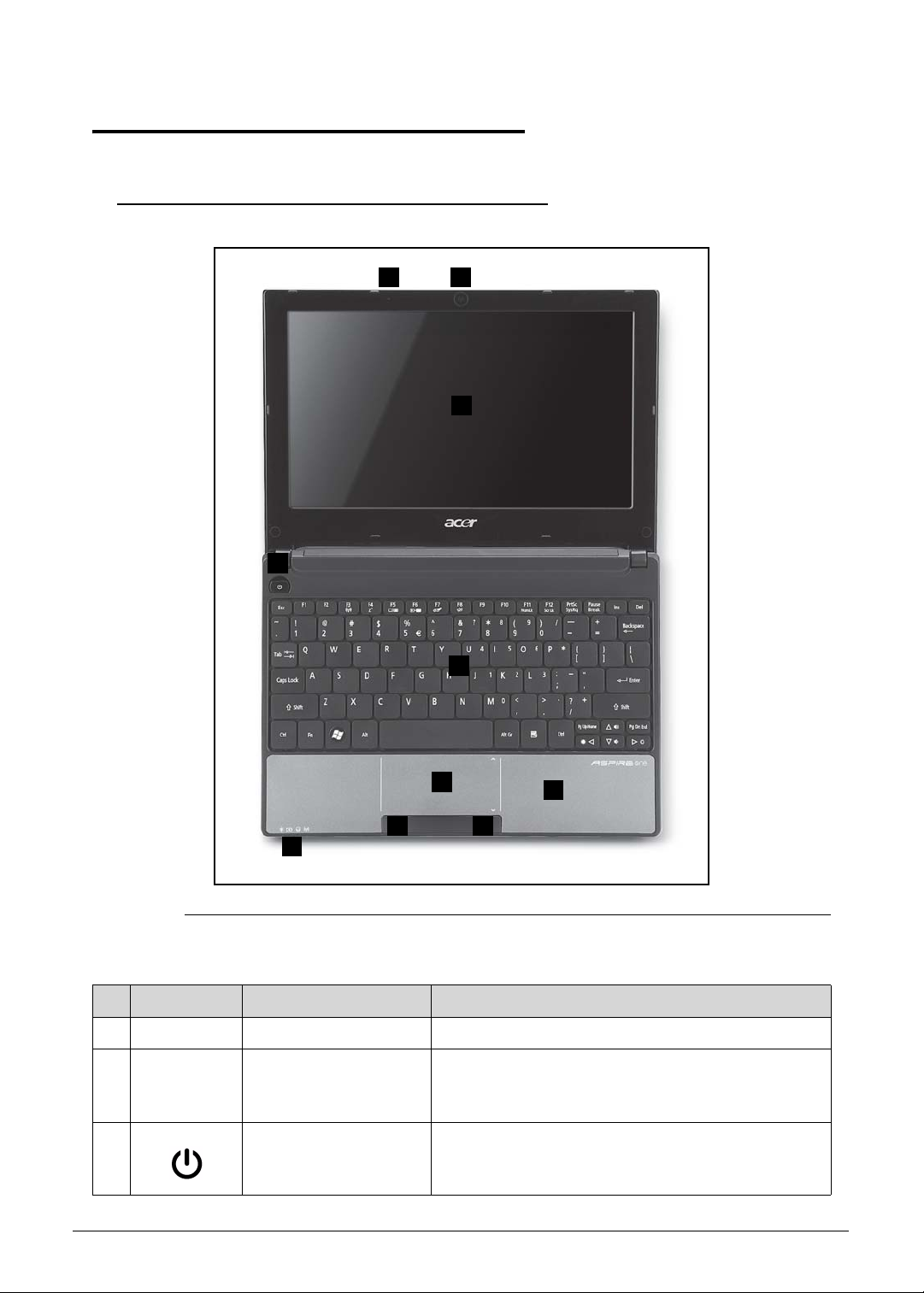
Notebook Tour 0
1 9
2
3
4
5
6
7 7
8
Top View 0
Figure 1-1. Top View
Table 1-1. Top View
# Icon Item Description
1
2 Display screen Also called Liquid-Crystal Display (LCD), displays
3 Power button Turns the computer on and off.
Microphone Internal microphone for sound recording.
computer output (Configuration may vary by
models).
1-10 Hardware Specifications and Configurations
Page 21
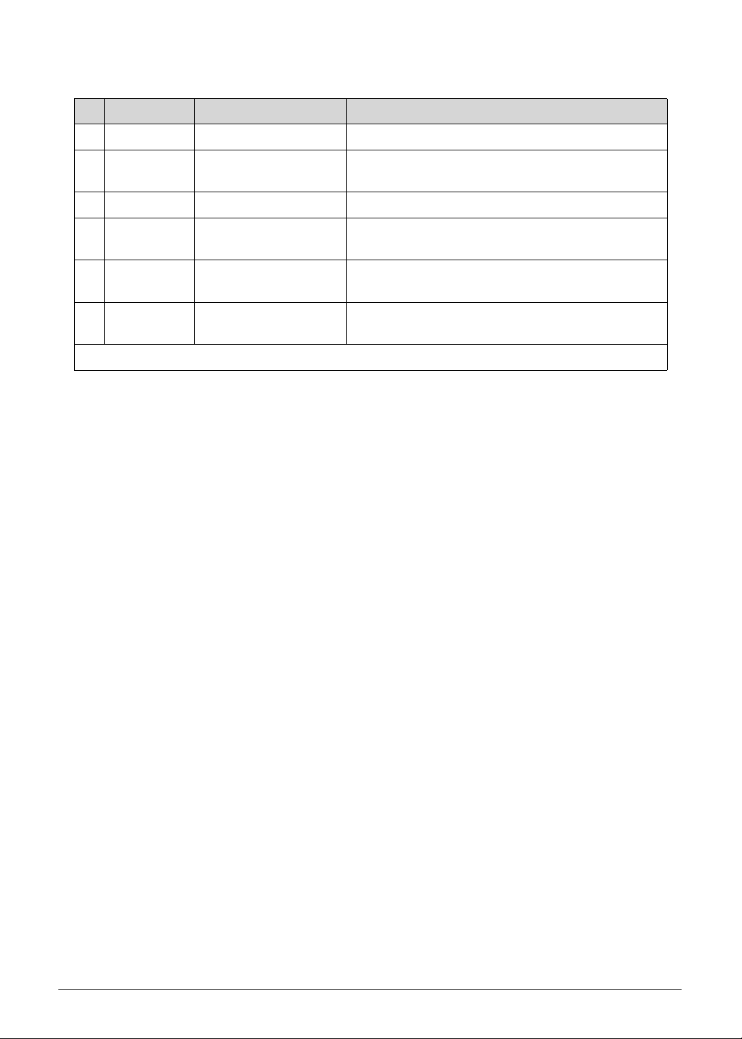
Table 1-1. Top View (Continued)
# Icon Item Description
4 Keyboard For entering data into your computer.
5 Touchpad Touch-sensitive pointing device which functions
like a computer mouse.
6 Status Indicators*
7 Click buttons (left and
right)
The left and right buttons function like the left and
right mouse buttons.
8 Palmrest Microphone Internal microphone for sound
recording.
9 Acer Crystal Eye
webcam
Web camera for video communication (only for
certain models).
* The front panel indicators are visible even when the computer cover is closed.
Hardware Specifications and Configurations 1-11
Page 22
Closed Front View 0
1
Figure 1-2. Front View
Table 1-2. Front View
# Icon Item Description
1 Power indicator Indicates the computer's power status.
Battery indicator Indicates the computer's battery status.
Charging: The light shows amber when the
battery is charging.
Fully charged: The light shows blue when in AC
mode.
HDD indicator Indicates when the hard disk drive is active.
Communication
indicator
Indicates the status of 3G/Wireless LAN
communication
Blue light on:
3G on / Wi-Fi on
3G on / Wi-Fi off
Orange light on:
3G off / Wi-Fi on
Not lit:
3G off / Wi-Fi off
1-12 Hardware Specifications and Configurations
Page 23
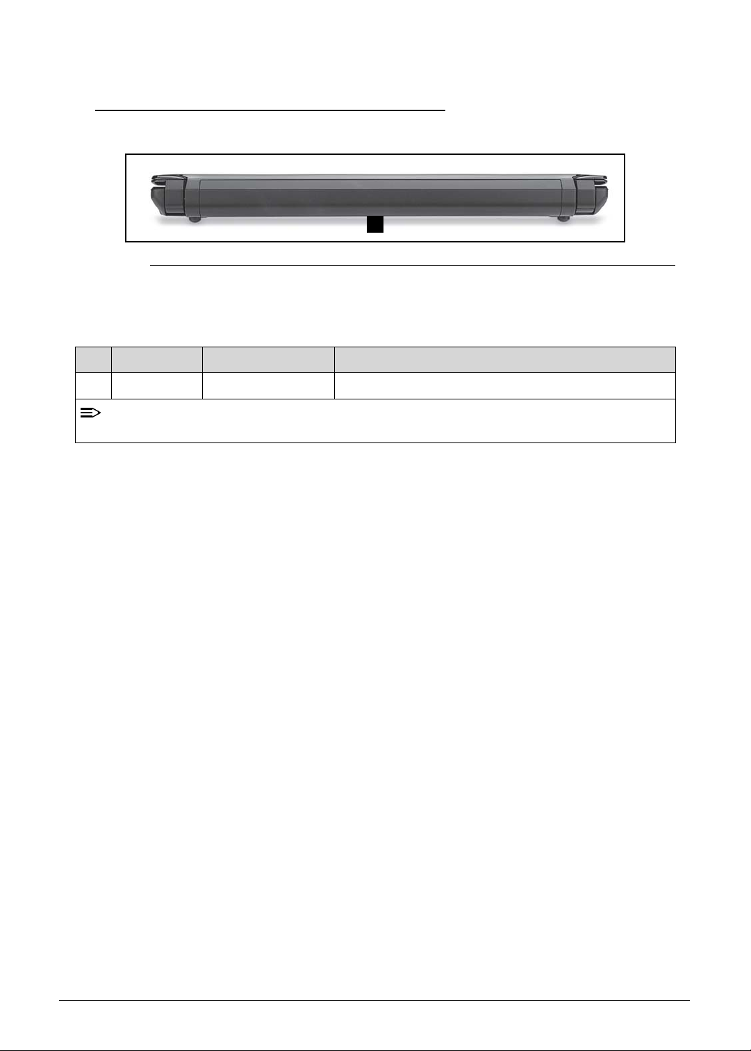
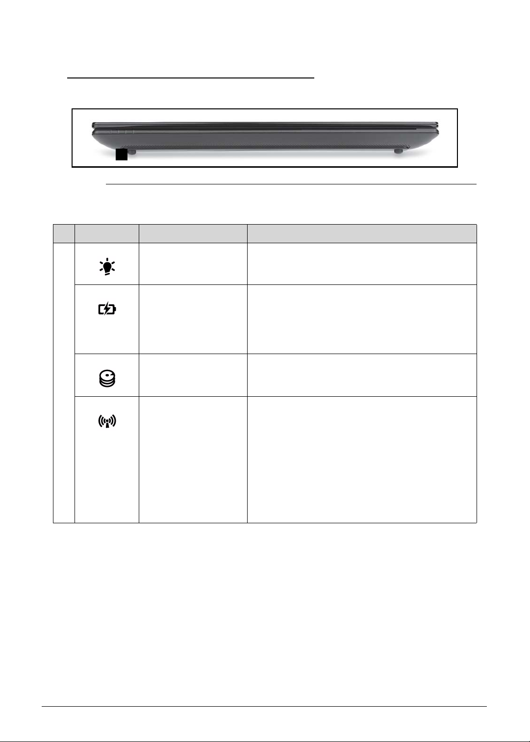
Rear View 0
NOTE:
1
Figure 1-3. Rear View
Table 1-3. Rear View
# Icon Item Description
1 Battery bay Houses the computer’s battery pack.
Your computer may be equipped with a different battery to the one in the picture.
Hardware Specifications and Configurations 1-13
Page 24
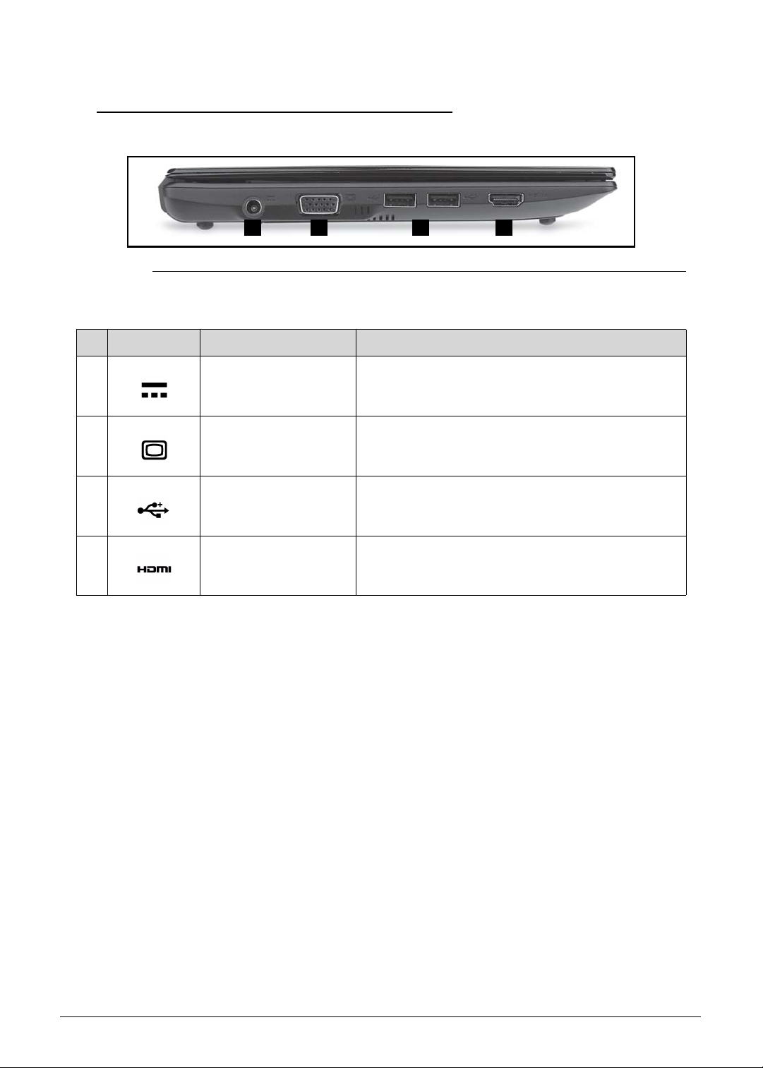
Left View 0
1 2 3 4
Figure 1-4. Left View
Table 1-4. Left View
# Icon Item Description
1 DC-in jack Connects to an AC adapter.
2
3
External display
(VGA) port
Connects to a display device (e.g., external
monitor, LCD projector ).
USB 2.0 ports Connects to USB 2.0 devices (e.g ., USB mouse,
USB camera).
4
HDMI port Supports high-definition digital video connections.
1-14 Hardware Specifications and Configurations
Page 25
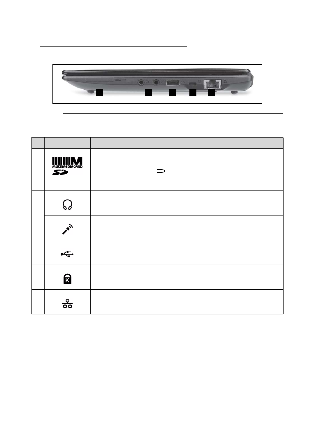
Right View 0
NOTE:
1 2 3 4 5
Figure 1-5. Right View
Table 1-5. Right View
# Icon Item Description
1 2-in-1 card reader Accepts Secure Digital (SD) and
MultiMediaCard (MMC).
Push to remove/install the card. Only one
card can operate at any given time.
2
Headphones/
speaker/ line-out jack
Connects to audio line-out devices (e.g.,
speakers, headphones).
3
Microphone jack Accepts inputs from external microphone s.
USB 2.0 port Connects to USB 2.0 devices (e.g., USB
mouse, USB camera).
4 Kensington lock slot Connects to a Kensington-compatible comp uter
security lock.
5 Ethernet (RJ-45) port Connects to an Ethernet 10/100 based
network.
Hardware Specifications and Configurations 1-15
Page 26
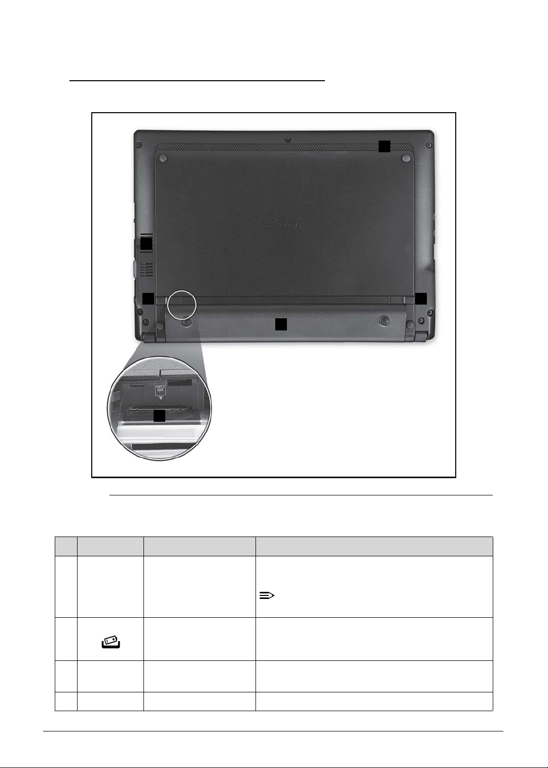
Base View 0
NOTE:
1
2
3
4
5
6
Figure 1-6. Base View
Table 1-6. Base View
# Icon Item Description
1 Ventilation slots and
cooling fan
2 Battery release latch/
lock
3 3G SIM card slot Accepts a 3G SIM card for 3G connectivity (only
4 Battery bay Houses the computer's battery pack.
Enable the computer to stay cool, even after
prolonged use.
Do not cover or obstruct the opening of the fan.
Releases the battery for removal.
for certain models).
1-16 Hardware Specifications and Configurations
Page 27

Table 1-6. Base View (Continued)
# Icon Item Description
5 Battery lock Locks the battery in position.
6 Speaker Emits audio from your computer.
Hardware Specifications and Configurations 1-17
Page 28
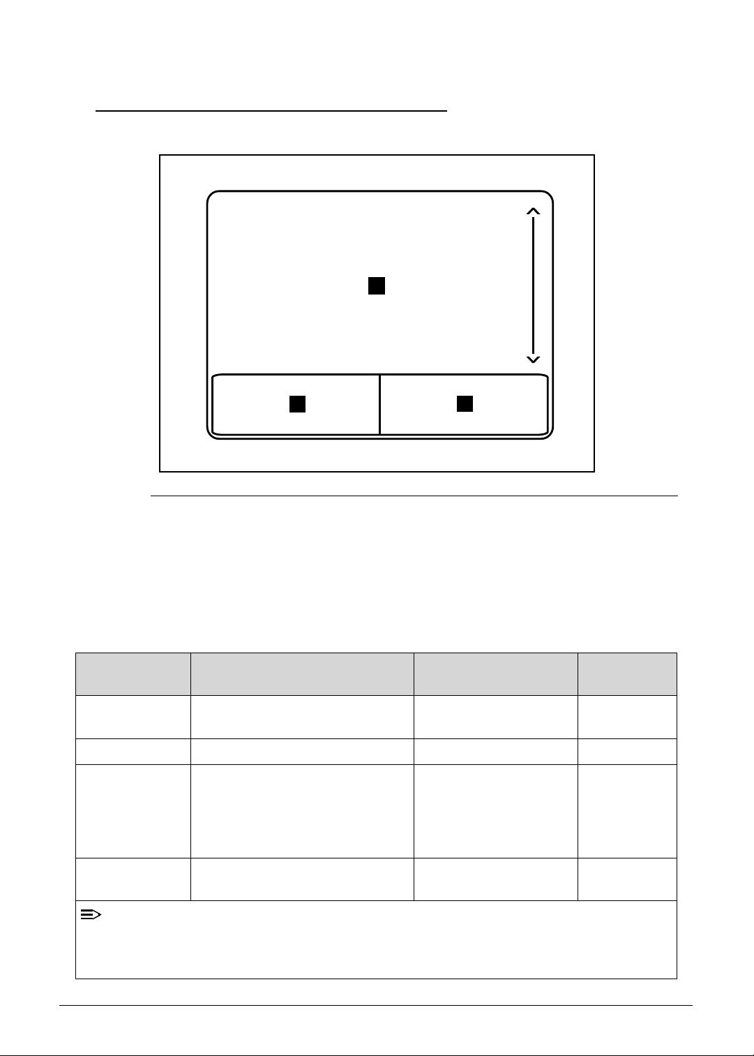
Touchpad Basics 0
NOTE:
1
3
2
Figure 1-7. Touchpad
Move your finger across the Touchpad (1) to move the cursor.
Press the left (2) and right (3) buttons located beneath the Touchpad to perform selection and
execution functions. These two buttons are the equivalent of the left and right buttons on a
mouse. Tapping on the Touchpad is the same as clicking the left button.
Table 1-7. Touchpad
Function Main TouchPad (1) Left Button (2) Right Button
Execute Tap twice (at the same speed as
double-clicking a mouse button).
Select Tap once. Click once.
Drag Tap twice (at the same speed as
double-clicking a mouse button);
rest your finger on the TouchPad
on the second tap and drag the
cursor.
Access context
menu
Quickly click twice.
Click and hold, then use
finger on the Touchpad
to drag the cursor.
Click once.
(3)
When using the TouchPad, keep it - and fingers - dry and clean. The TouchPad is sensitive
to finger movement; hence, the lighter the touch, the better the response. Tapping too hard
will not increase the TouchPad’s responsiveness.
1-18 Hardware Specifications and Configurations
Page 29
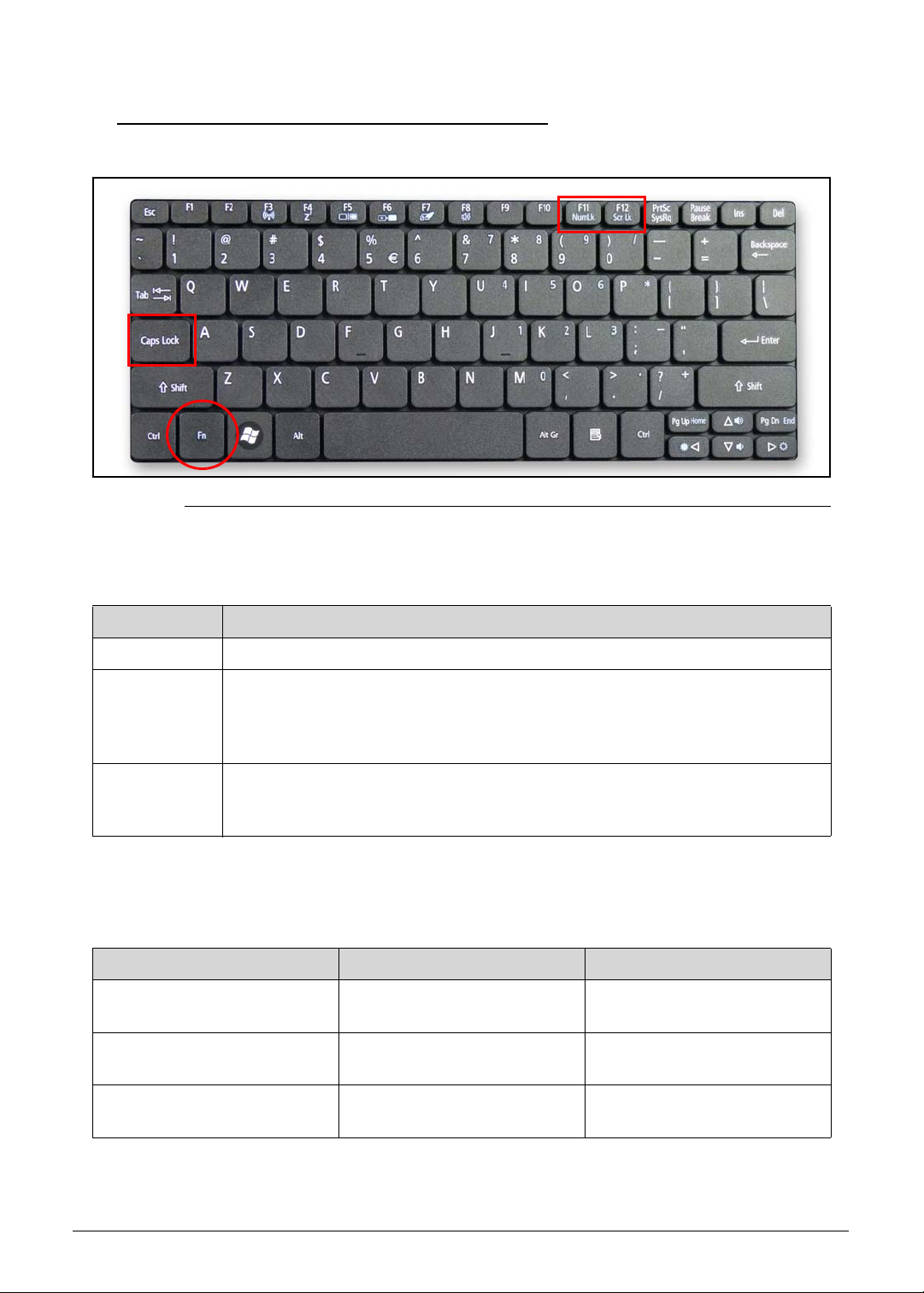
Using the Keyboard 0
Figure 1-8. Keyboard Lock Keys
The keyboard has three lock keys which can be toggled on and off. (Table 1-8)
Table 1-8. Keyboard Lock Keys
Lock key Description
Caps Lock Wh en Caps Lock is on, all alphabetic characters typed are in uppercase.
Num Lock When Num Lock is on, the embedded keypad is in numeric mode. The keys
function as a calculator (complete with the arithmetic operators +, -, *, and /).
Use this mode when doing a lot of numeric data entry. A better solution would
be to connect an external keypad.
Scroll Lock
<Fn> + <F12>
The embedded numeric keypad functions like a desktop numeric keypad. It is indicated by
small characters located on the upper right corner of the key caps. To simplify the keyboard
legend, cursor-control key symbols are not printed on the keys. (Tabl e 1-9)
Table 1-9. Embedded Numeric Keyp ad
Desired access Num Lock on Num Lock off
Number keys on embedded
keypad
Cursor-control keys on
embedded keypad
Main keyboard keys Hold <Fn> while typing letters
When Scroll Lock is on, the screen moves one line up or down when the up o r
down arrow keys are pressed respectively. Scroll Lock does not work with
some applications.
Type numbers in a normal
manner.
Hold <Shift> while using
cursor-control keys.
on embedded keypad.
Hold <Fn> while using
cursor-control keys.
Type the letters in a normal
manner.
Hardware Specifications and Configurations 1-19
Page 30
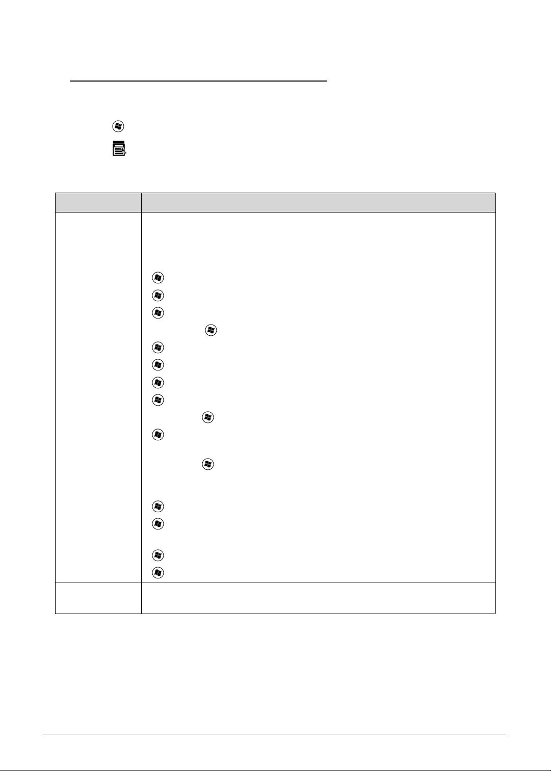
Windows Keys 0
The keyboard has two keys that perform Windows-specific functions.
Windows Logo key
Application key
Table 1-10. Windows Keys
Key Description
Windows Logo
key
Pressed alone, this key has the same ef fect as clicking on the Windows Start
button; it launches the Start menu. It can also be used with other keys to
provide a variety of functions.
Functions supported by Windows XP, Windows Vista, and Windows 7:
< >: Open or close the Start menu
< > + <R>: Open the Run dial og box
< > + <M>: Minimizes all windows
<SHIFT> + < > + M: Undo minimize all windows
< > + <F1>: Show the help window
< > + <E>: Open Windows Explorer
< > + <F>: Search for a file or folder
< > + <D>: Show the desktop
<CTRL> + < > + <F>: Search for computers (if you ar e on a network)
< > + <L>: Lock your computer (if you are connected to a network
domain), or switch users (if you're not connected to a network domain)
<CTRL> + < > + <TAB>: Moves focus from Start menu, to the Quick
Launch toolbar , to the system tray (use RIGHT ARROW or LEFT ARROW to
move focus to items on the Quick Launch toolbar and the system tray)
< > + <TAB>: Cycle through programs on the taskbar
< > + <BREAK>: Display the System Properties dialog box
Functions supported by Windows XP:
< > + <BREAK>: Show the System Properties dialog box
< > + <U>: Open Ease of Access Center
Application key This key has the same effect as clicking the right mouse button; it opens the
application's context menu.
1-20 Hardware Specifications and Configurations
Page 31

Hotkeys 0
The computer employs hotkeys or key combinations to access most of the computer's
controls like screen brightness and volume output.
Figure 1-9. Keyboard Hotkeys
To activate hotkeys, press and hold the <Fn> key before pressing the other key in the hotkey
combination.
Table 1-11. Keyboard Hotkeys
Hot key Icon Function Description
<Fn> + <F3> Communication switch Enables/disables the computer’s
communication devices.
(Communication devices may
vary by configuration.)
<Fn> + <F4> Sleep Puts the computer in Sleep
mode.
<Fn> + <F5> Display toggle Switches display output between
the display screen, external
monitor (if connected) and both.
<Fn> + <F6> Screen blank Turns the display screen
backlight off to save power. Press
any key to return.
<Fn> + <F7> Touchpad toggle Turns the touchpad on and off.
<Fn> + <F8> Speaker toggle Turns the speakers on and off.
Hardware Specifications and Configurations 1-21
Page 32

Table 1-11. Keyboard Hotkeys (Continued)
Hot key Icon Function Description
<Fn> + <F11> Num Lock When Num Lock is on, the
embedded keypad is in numeric
mode. The keys function as a
calculator (complete with the
arithmetic operators +, -, *, and /).
Use this mode when you need to
do a lot of numeric data entry. A
better solution would be to
connect an external keypad.
<Fn> + <F11> only for certain
models.
<Fn> + <F12> Scroll Lock When Scroll Lock is on, the
screen moves one line up or
down when you press the up or
down arrow keys respectively.
Scroll Lock does not work with
some applications.
<Fn> + <
<Fn> + <
<Fn> + <
<Fn> + <
>
>
>
>
Brightness up Increases the screen brightness.
Brightness down Decreases the screen brightness.
Volume up Increases audio volume.
Volume down Decreases audio volume.
1-22 Hardware Specifications and Configurations
Page 33

Using the Communication Key 0
NOTE:
NOTE:
Here you can enable and disable the various wireless connectivity devices on your computer.
Press Fn + F3 to bring up the Launch Manager window panel. (Figure 1-10)
A red toggle indicates the device is off. Click On to enable wireless/Bluetooth connection.
Click Off to disable connection.
Figure 1-10. Launch Manager Dialog
Communication devices may vary by model.
Hardware Specifications and Configurations 1-23
Page 34

System Block Diagram 0
Figure 1-11. System Block Diagram
1-24 Hardware Specifications and Configurations
Page 35

Specification Tables 0
NOTE:
Computer specifications
Item Metric Imperial
Dimensions
Length 258.5mm 10.18”
Width 184.0mm 7.24”
Height
(front to rear)
25.7mm (Wedge panel) rear
Weight (equipped with optical
drive, flash drive, and battery)
Input power
Operating voltage 18.55V ~ 19.95V
Operating current 40W 2.15A (Max)
Temperature
Operating (not writing to
optical disc)
Operating (writing to optical
disc)
Nonoperating -20°C to 60°C -4°F to 140°F
Relative humidity
Operating 10% to 80%
Nonoperating 5% to 80%
11mm(Front)
24.0mm (Slim panel), rear
1086.92g (3 cell)
1199.57g (6 cell)
0°C to 35°C 32°F to 95°F
N/A N/A
0.43” (Front)
0.95” (Slim panel), rear
1.01” (Wedge panel) rear
2.39 lb (3 cell)
2.65 lb (6 cell)
Maximum altitude (unpressurized)
Operating -15m~3,084m -50ft~10,000ft
Nonoperating -15m~12,192m -50ft~40,000ft
Shock
Operating 105 g, 2ms, half-sine
Nonoperating 200 g, 2ms, half-sine
Random vibration
Operating 0.6 g zero-to-peak, 5 Hz to 500 Hz, 0.25 oct/min sweep rate
Nonoperating 1.50 g zero-to-peak, 10 Hz to 500 Hz, 0.25 oct/min sweep rate.
Applicable product safety standards specify thermal limits for plastic surfaces. The computer
operates well within this range of temperatures.
Hardware Specifications and Configurations 1-25
Page 36

System Board Major Chips
Item Specification
Core logic AMD Brazos FT1 9W
Hudson M1 FCH
VGA UMA
LAN 10/100Mbps, Atheros AR8152-BL1A-RL
USB 2.0 Hudson M1 FCH
Super I/O controller N/A
Bluetooth USB type, ver 3.0, BRM 2070, ATH BU12
Wireless 3rd Party WiFi 1x1/2x2 802.11BGN / BG, Atheros HB95, Atheros
HB95BG, Broadcom 4313, Reltek RTL8191SE
PCMCIA N/A
Audio codec Conexant 20584
Card reader ENE UB6252NF A2-110 QFN 32P
3G EM770W-Rev2
Processor
Item Specification
CPU type AMD Brazos FT1 9W
Ontario (C50) 1.0G, 2Core
CPU package BGA 413P
Core Logic L2 Cache Size: 1MB
Chipset Hudson M1 FCH
Processor Specifications
Item CPU Speed
(GHz)
Ontario
(C50)
1 2 2.5 GT/s 40 1MB BGA 413P 0.8750C~
Cores/
Threads
Bus
Speed
(FSB/
DMI/QBI)
Tech
(nm)
Mfg
Cache
Size
Package Voltage
1.3500
1-26 Hardware Specifications and Configurations
Page 37

CPU Fan True Value Table (For Windows mode)
CPU Temperature Fan Speed (RPM) SPL Spec (dBA)
50 4600 26
65 5300 29
75 5800 31
80 6300 34
Throttling 50%: On= 95°C; OFF=85°C
OS shut down at 100°C; H/W shut down at 92°C
CPU Fan True Value Table (For DOS mode)
CPU Temperature Fan Speed (RPM) SPL Spec (dBA)
35 4600 26
40 5300 29
45 5800 31
50 6300 34
Throttling 50%: On= 95°C; OFF=85°C
OS shut down at 100°C; H/W shut down at 92°C
System Memory
Item Specification
Memory controller Built in at CPU
Memory size DDRIII 1333 1G/2G
DIMM socket number 1
Supports memory size per socket 1G/2G
Supports maximum memory size 2G/per DIMM
Supports DIMM type DDRIII
Supports DIMM Speed 1333
Support DIMM voltage 1.5V
Supports DIMM package DDRIII, SO-DIMM, 204 pins
Hardware Specifications and Configurations 1-27
Page 38

Memory Combinations
Slot 1 (MB) Total Memory (MB)
1024 1024
2048 2048
Video Interface
Item Specification
Chipset ATI Mobility Radeon HD 6250
Package FT1 BGA, 413-Ball, 19x19mm
Interface LVDS
Compatibility TBD
Sampling rate 280 Mhz
BIOS
Item Specification
BIOS vendor Insyde
BIOS Version 1.00
BIOS ROM type MX25L1606E, W25Q16BV
BIOS ROM size 2 MB
Features
Insyde code base
Flash ROM 2 MB
Support Acer UI
Support multi-boot
Suspend to RAM (S3)/Disk (S4)
Various hot-keys for system control
Support SMBIOS 2.3 ,PCI2.2.
DMI utility for BIOS serial number configurable/asset tag
Support PXE
Support WinFlash
Wake on LAN from S3
Wake on LAN from S5 in AC mode
System information
HDD password
Refer to Acer BIOS specification.
1-28 Hardware Specifications and Configurations
Page 39

LAN Interface
Item Specification
LAN Chipset Atheros AR8152-BL1A-RL
LAN connector type RJ45
LAN connector location JRJ45 on right side
Features MAC Features
EEE 802.3x compliant flow control support
Interrupt coalescing
Internal transmit and receive FIFO buffers
Descriptor ring management for Tx/Rx
IPv4 and IPv6 support
802.3u support
IEEE 802.1Q VLAN feature
Supports remote wake-up (including AMD Magic packet and
MS Wake-up frame) in both ACPI and APM
Device and Technology Features
Embedded switching regulator
Embedded LDO regulator with PNP transistor embedded
Requires only a single input power supply:3.3V. On-chip
egulators provide all the other required voltages
Supports 25MHz external shared-clock source
Loop back modes for diagnostics
256 byte memory (using eFuse) embedded on chip
Small footprint 40-pin QFN (5x5 mm) package with
dramatically improved thermal and electrical characteristics
over LQFP packaging
Fully Programmable LED functions
PHY Features
Integrated PHY for 10/100 Mbps
IEEE 802.3 Auto-Negotiation support
IEEE 802.3 PHY compliance and compatibility
Supports automatic MDI/MDIX functions
Cable Diagnostic Test (CDT) for open, short cable, cable
length detection, and incorrect or mismatched impedance
Cable length to 180 meters
IEEE 802.3az support
Hardware Specifications and Configurations 1-29
Page 40

Item Specification
LAN Interface (continued)
Host Offloading Features
IP, TCP, and UDP checksum offload capabilities
Transmit TCP segmentation
IPv6 offload
Advanced packet filtering, including promiscuous (unicast
and multicast) transfer mode and multicast frame support
IEEE 802.1Q VLAN support Power Management Features
Supports PM states: L0, L1, L0s
Support wake event generation from all PM states including
D3hot
Wake event signaling by WAKE# signal mechanisms
Compliance with PCI Express power management and ACPI
Wake on LAN support
Built-in intelligence allow sleep and ultra-low power options
that do not require BIOS integration to perform the full
wake-to-sleep-to-wake cycle
Intelligently reduces power based upon cable length
detected
Green Ethernet feature support
Supports Energy Star 5.0
PCIE Features
PCI Express base 1.1 compliant
Supports single, one-lane PCIE connection
Memory and configuration transaction
Interrupt messaging
PCIE baseline and advanced error reporting
Supports max payload size (128 bytes) and read request
size (4096 bytes)
Supports SMBus initialization
Supports PME and error messaging
CLKREQn support
Supports up to 25% over-clocking without requiring BIOS
support - See Note below
Keyboard
Item Specification
Type New Acer flat keyboard
Total number of keypads 84-US/85-UK /88-JA keys
Windows logo key Yes
Internal & external keyboard
Plug USB keyboard to the USB port directly: Yes
work simultaneously
1-30 Hardware Specifications and Configurations
Page 41

Item Specification
Keyboard (continued)
Features
Phantom key auto detect
Overlay numeric keypad
Support independent pgdn/pgup/pgup/home/end keys
Support reverse T cursor keys
Factory configurable different languages by OEM customer
Hard Disk Drive (AVL components)
Item Specification
Vendor & Model
Name
HTS545016B9A
300
MK1665GSX
ST9160314AS
Capacity (GB)
160GB 250GB 320GB 160GB
Bytes per sector 512
512
512
HTS545025B9A
300
MK2565GSX
ST9250315AS
WD2500BPVT-
22ZEST0
512
512
512
4096
HTS545032B9A
300
WD3200BPVT22ZEST0
HTS543232A7A
384
512
4096
512
WD1600BPVT22ZEST0
4096
Data heads 2
1
2
2
2
2
1
Drive Format
Disks 1
1
1
2
2
2
1
Spindle speed
5400
(RPM)
Performance Specifications
Buffer size 8 MB
Interface SATA
Fast data transfer
3.0Gbits/s
rate (Mbits / sec,
max)
3
1
2
2
2
1
1
1
Hardware Specifications and Configurations 1-31
Page 42

Item Specification
Hard Disk Drive (continued)
Media data transfer
rate
(Mbytes/sec max)
DC Power Requirements
Voltage tolerance 5V
Super-Multi Drive (not available with this model)
Item Specification
Vendor & Model name
Performance Specification
Transfer rate (KB/sec)
Buffer Memory
Interface
Applicable disc format
Loading mechanism
Power Requirement
845Mbits/s
1273.3Mbits/s
1175Mbits/s
845Mbits/s
1031.7Mbit/s
1175Mbits/s
108Mbytes/s
845Mbytes/s
108Mbytes/s
994Mbits/s
108Mbytes/s
Input Voltage
BD Drive (not available with this model)
Items Specifications
Vendor & Model
name
Performance
Specification
Transfer rate
(KB/sec)
Buffer Memory
Interface
Applicable disc
format
Loading mechanism
Power Requirement
Input Voltage
1-32 Hardware Specifications and Configurations
Page 43

LED 10.1”
Item Specification
Vendor/Model name AUO/B101AW06 V1 (HW:0A)
AUO/B101AW03 V0 (HW:2A)
AUO/B101EW02 V0
Samsung/LTN101AT01-A01
CMO/N101L6-L0D
CMO/N101L6-L0B
Screen Diagonal (mm) 255.573 mm (10.06”)
Active Area (mm) 222.72mm X125.28mm (8.77” x 4.93”)
Display resolution (pixels) 1024x 600x 3(RGB)
Pixel Pitch (mm) 0.2175 x 0.2088 (0.009” x 0.008”)
Typical White Luminance
2
(cd/m
) also called Brightness
200 cd/m2
Contrast Ratio 300min/400 typ
Response Time (Optical Rise
16 ms / 25 ms (typ/max)
Time/Fall Time) msec
Typical Power Consumption
2.46 W
(watt)
Weight (without inverter) 170 max
Physical Size (mm) 245.5 mm x 147mm x 3.6 max (9.67” x 5.79” x 0.14”)
Electrical Interface 1 channel LVDS
Viewing Angle (degree)
Horizontal (Right) CR = 10
40 (Right) / 40 (Left) / 10 (Upper) / 30 (Lower) min.
(Left)
Vertical (Upper) CR = 10
(Lower)
LCD Inverter (not available with this model)
Item Specification
Vendor & Model name
Brightness conditions
Input voltage (v)
Input current (mA)
Output voltage (V, RMS)
Output current (mA, RMS)
Output voltage frequency
(KHz)
Hardware Specifications and Configurations 1-33
Page 44

Display Supported Resolution (LCD Supported Resolution)
Resolution 16 bits 32 bits Intel NVIDIA ATI
800x600p/60Hz 16:9 V V X X V
1024x768p/60Hz 16:9 V V X X V
1280x600/60Hz 16:9 X X X X X
1280x720/60Hz 16:9 V V X X V
1280x768/60Hz 16:9 X X X X X
1360x768/60Hz 16:9 X X X X X
1366x768/60Hz 16:9 X X X X X
Graphics Controller
Item Specification
VGA Chip UMA
Supports No
Display Supported Resolution (GPU Supported Resolution)
Resolution 16 bits 32 bits Intel NVIDIA ATI
800x600p/60Hz 16:9 X X X X X
1024x768p/60Hz 16:9 X X X X X
1280x600/60Hz 16:9 X X X X X
1280x720/60Hz 16:9 X X X X X
1280x768/60Hz 16:9 X X X X X
1360x768/60Hz 16:9 X X X X X
1366x768/60Hz 16:9 X X X X X
Bluetooth Interface
Item Specifications
Chipset Atheros BU12 Broadcomm 2070
Data throughput TX 1.2Mbits/sec
RX 1.2Mbits/sec
Protocol 3.0+HS 3.0+HS
Interface USB 2.0 USB 2.0
Connector type SM06B-XSRK-ETB SM06B-XSRK-ETB
TX 1.2Mbits/sec
RX 1.2Mbits/sec
Supported protocol 802.15.1 802.15.1
1-34 Hardware Specifications and Configurations
Page 45

Bluetooth Module
Item Specifications
Controller BRM 2070 (T77H114.01)
Features
BT 3.0
Camera
Item Specification
Vendor and Model
Chicony 1.3M CH9665SN (CNF9157)
Suyin 1.3M SY9665SN
Liteon 1.3M LT9665AL (09P2SF119)
Type 1.3M
Mini Card
Item Specification
Number supported 2
Features
1 mini card slot (for WLAN)
1 mini card slot(for 3G)
3G Card
Item Specification
Features
Huawei EM770W Rev02
Audio Codec and Amplifier (amplifier not available)
Item Specification
Audio Controller Conexant 20584
Features
24-bit, 2 pairs of independent DACs and 3 pairs of
independent ADCs
ProCoustic headphone driver delivers 50 mW into 32 ? load
with no pop, eliminating the need for an external amplifier
and DC-blocking capacitors
Integrated 5 V to 3.3 V low-dropout voltage regulator for
improved audio performance, eliminating need for external
regulator or power transistor.
Integrated 3.3 V to 1.8 V low-dropout voltage regulator, used
to power digital blocks
Integrated 2 WRMS (per channel) class-D stereo speaker
amplifier with Spread Spectrum and 10-kV ESD withstand
capability
Hardware Specifications and Configurations 1-35
Page 46

Item Specification
Audio Codec and Amplifier (continued)
Features
Digital Microphone interface with internal MIC boost
supporting 2 digital microphone elements
Works with all digital microphones.
Internal microphone boost
Digital: 0, 12, 24, 36, 48 dB
Analog: 0, 10, 20, 30, 40 dB
Microphone Security Control
Please contact Conexant Sales/FAE for additional
confidential document to disable the bit in micr ophone from
the BIOS.
Exceeds Windows Vista and Windows 7 Desktop and
Notebook Premium Logo Requirements, WLP4.0
D-Flex power management exceeds Intel ECR 15B
requirements, and features Wake-On-PCBeep functionality
Hardware Headphone limiter bit (supports GS Mark
EN50332-2)
Compliant with Intel High Definition Audio Specification Rev.
1.0
Supports both 1.5 V and 3.3 V signaling with the core logic
chipset
Retaskable ports
Configure between Headphone and Line-out or between
Mic and Line-in
Independent sampling rate for DAC and ADC; supports audio
formats ranging from 16-bit, 44.1 kHz to 24-bit, 192 kHz for
DACs, and from 16-bit, 44.1 kHz to 24-bit, 96 kHz for ADCs.
Pop Shield: pops and clicks reduction circuitry, including
class-D speaker outputs
Jack sense detects up to 8 jacks using only two sense pins
Dual Sony Philips Digital Interface (S/PDIF) outputs
Digital Mixer
Simultaneous DAC and SPDIF engines
+3.3 V analog and I/O operation; uses Vaux for power
management modes
1-36 Hardware Specifications and Configurations
Page 47

Item Specification
Audio Codec and Amplifier (continued)
Features (continued)
Audio Director for Headphone and Internal Speakers
Redirection (optional).
Supporting Classic Mode
Vista Multi-Stream
Custom Multi-Stream Mode
Voice Processing Algorithms (optional)
End-to-end Noise Reduction (patent pending)
Multi-band Acoustic Echo Cancellation
Side Noise Rejection Beam Forming
SmartAudio GUI (optional) - advanced audio control
Digital Parametric SmartEQ with Dynamic Range
Compression (DRC)
Enhances the sound quality on low cost speakers
Night Mode
3D Expander
Third-party Logo software support
Andrea
Creative Labs
Dolby
®
Supports 32-bit/64-bit Windows OS and Linux
Available in 48-/56-QFN and in 48-/64-QFP packages
Amplifier N/A
Features N/A
Fortemedia
MaxxAudio
Sonic FocusTM
SRS
®
Hardware Specifications and Configurations 1-37
Page 48

Audio Interface
Item Specification
Audio Controller Conexant 20584
Audio onboard or optional On board
Mono or Ster eo Stereo
Resolution Support 16/24bit PCM
Compatibility HD audio Interface
Sampling rate Sample rate up to 192Khz resolution VSR (Variable Sampling
Rate)
Internal microphone Yes
Internal speaker/quantity Yes/(1W speakers x1)
Wireless Module 802.11b/g/n
Item Specification
Chipset Broadcomm94313 Atheros AR9285(FOXCONN)
Data throughput TX 150Mbps
RX 150Mbps
Protocol 802.11b 802.11g 802.11n 802.11b 802.11g 802.11n
Interface PCI-E PCI-E
Chipset Atheros Ar9285(FOXCONN) Atheros Ar9285(Liteon)
Data throughput TX 150Mbps
RX 150Mbps
Protocol 802.11b 802.11g 802.11n 802.11b 802.11g 802.11n
Interface PCI-E PCI-E
Battery
Item Specification
Vendor & Model name SANYO AL10A SANYO AL10B
Battery Type Li-ion Li-ion
Pack capacity 2200mAh 4400mAh
Number of battery cell 3 6
TX :65Mbps for 20Mhz channel and
150Mbps for 40Mhz channel
RX :65Mbps for 20Mhz channel and
150Mbps for 40Mhz channel
TX 150Mbps
RX 150Mbps
Package configuration 3S1P 3S2P
1-38 Hardware Specifications and Configurations
Page 49

VRAM (not available with this model)
Item Specification
Chipset N/A
Memory size N/A
Interface N/A
USB Port
Item Specification
USB compliance level USB 2.0
Protocol OHCI
Number of USB port(s) 3
Location Two at the left side and one at right side
Output Current 1.0A for each connector
HDMI Port
Item Specification
Compliance level v1.4
Data throughput 3.4 Gbit/s
Number of HDMI port(s) 1
Location JHDMI on left side
AC Adapter
Item Specification
Input rating 40W
Maximum input AC current 1.2A Max at 100Vac input voltage
Inrush current No damage at 240Vac
Efficiency Refer to EPA 2.0
Hardware Specifications and Configurations 1-39
Page 50

System Power Management
Item Specification
Mech. Off (G3) Al devices in the system are turned off completely.
Soft Off (G2/S5) OS initiated shutdown. All devices in the system are turned off
completely.
Working (G0/S0) Individual devices such as the CPU and hard disc may be
power managed in this state.
Suspend to RAM (S3)
CPU set power down
VGA Suspend
PCMCIA Suspend
Audio Power Down
Hard Disk Power Down
CD-ROM Power Down
Super I/O Low Power mode
Save to Disk (S4) Also called Hibernation Mode. System saves all system states
anddata onto the disc prior to power off the whole system.
1-40 Hardware Specifications and Configurations
Page 51

Card Reader
Item Specification
Chipset ENE UB6252
Package 32 Pin QFN
Maximum supported size SD card: SD Memory Card Specification Version 2.0
xD card: Compliant with xD-Picture Card Specification Version 1.2
MMC card: MultiMedia Card Specification Version 4.2
MS Pro: Memory Stick PRO Format Specification Version 1.x
Features
32 Pin QFN
Built-in 250mA Power MOS for memory card
Over Current Protection and Over Temperature Protection
Built-in LDO
Power Saving
Power Down when no memory card is inserted
Power Idle (Selective Suspend)
USB Interface
Compliant with Universal Serial Bus Specification Revision 2.0
Compliant with Universal Serial Bus Mass Storage Class Bulk-Only
Transport Specification Revision 1.0
Support both High-Sp eed (480 Mbps) and Full-Speed (12
Mbps) Data Transfer
Embedded High Speed/Full Speed Transceiver
Clock source: 12MHz crystal
Secure Digital/MultiMedia Card Interface
Compliant with SD Memory Card Specification Version 2.0
Compliant with MultiMedia Card Specification Version 4.2
Support High Spe ed SD 4-bit Data Transfer Mode
Support High Spe ed MMC 8-bit Data Transfer Mode
Support Write Protection Switch
Memory Stick Interface
Compliant with Memory Stick PRO Format S pecification V ersion
1.x
Compliant with Memory Stick PRO-HG Duo Format
Specification Version 1.x
Support 4-bit and 8-bit Parallel Data Transfer Mode
xD- Picture Card Interface
Compliant with xD-Picture Card Specification Version 1.2
(support multi-plane)
Support Hardware ECC (1-bit correction and 2-bits detection)
Generation
Hardware Specifications and Configurations 1-41
Page 52

Item Specification
Card Reader (continued)
Embedded Program memory and Data SRAM
Miscellaneous Function
One Global Traffic LED Pin
ENE Driver
Windows 2000, Windows XP, Windows Vista, Windows 7
Linux
System LED Indicator
Item Specification
Lock N/A
System state Dual color: Blue/Orange
Power on: Blue
Standby: Breeze mode Orange ( 1 sec on/ 3 sec off)
Entering Hibernation: Blinking mode Orange (1 sec on/ 1 sec
off)
Hibernation/Power off: N/A
HDD access state Blue color
Fast blinking when HDD/SSD/Card reader is running or
accessing to data
Wireless state Dual color (Blue/Orange)
3G only: Blue (either BT is on or off)
3G+WiFi: Blue (either BT is on or off)
WiFi only: Orange (either BT is on or off)
Both off: N/A (either BT is on or off)
(WiMax is the same as WiFi behavior)
BT has no LED. So above behavior is unchange d no matter BT
is on or off
Power button backlight Blue color
Power on: Blue
Power off: N/A
Battery state Dual color: Blue/Orange
Fully charged: Blue
Under charging: Orange
Battery low: Breeze mode Orange (1 sec on, 3 sec off)
Battery critical low (less than 3%) or abnormal battery situation:
Blinking mode Orange: (1 sec on, 1 sec off)
Using battery or not connected to AC power: N/A
1-42 Hardware Specifications and Configurations
Page 53

System DMA Specification
Legacy Mode Power Management
DMA0 N/A
DMA1 N/A
DMA2 N/A
DMA3 N/A
DMA4 Direct memory access controller
DMA5 N/A
DMA6 N/A
DMA7 N/A
*ExpressCard controller can use DMA 1, 2, or 5.
System Interrupt Specification
Hardware IRQ System Function
IRQ0 High precision event timer
IRQ1 Standard PS/2 Keyboard
IRQ8 High precision event timer
IRQ12 XXXX PS2 Port TouchPad
IRQ13 Numeric data processor
IRQ81-IRQ190 Microsoft ACPI-compliant system
IRQ16 High Definition Audio Controller
PCI standard PCI-to-PCI bridge
IRQ17 Standard Enhanced PCI to USB Host Controller
IRQ18 Atheros AR8152/8158 PCI-E Fast Ethernet Controller (NDIS 6.20)
Standard OpenHCD USB Host Controller
IRQ19 XXXX Wireless Network Adapter
High Definition Audio Controller
Standard AHCI 1.0 Serial ATA Controller
IRQ(-2) AMD Radeon HD 6250 Graphics
Hardware Specifications and Configurations 1-43
Page 54

System IO Address Map
I/O address (hex) System function (shipping configuration)
000 - 00F DMA controller
000 - CF7 PCI bus
010 - 01F Motherboard resources
020 - 021 Interrupt controller
02E - 02F Motherboard resources
040 - 043 System timer
060 - 060 Standard PS/2 Keyboard
061 - 061 System speaker
062 - 062 Microsoft ACPI-Compliant Embedded Controller
064 - 064 Standard PS/2 Keyboard
066 - 066 Microsoft ACPI-Compliant Embedded Controller
070 - 071 System CMOS/real time clock
072 - 073 Motherboard resources
080 - 080 Motherboard resources
081 - 08F DMA controller
092 - 092 Motherboard resources
0A0 - 0A1 Programmable interrupt controller
0B0 - 0B1 Motherboard resources
0C0 - 0DF DMA controller
0F0 - 0FE Numeric data processor
3B0 - 3BB AMD Radeon HD 6250 Graphics
3C0 - 3DF AMD Radeon HD 6250 Graphics
400 - 4CF Motherboard resources
4D0 - 4D1 Motherboard resources
4D6 - 4D6 Motherboard resources
680 - 6FF Motherboard resources
77A - 77A Motherboard resources
C00 - C01 Motherboard resources
C14 - C14 Motherboard resources
C50 - C52 Motherboard resources
C6C - C6C Motherboard resources
C6F - C6F Motherboard resources
1-44 Hardware Specifications and Configurations
Page 55

I/O address (hex) System function (shipping configuration)
System IO Address Map (continued)
CD0 - CDB Motherboard resources
System I/O Address Specifications
I/O address (hex) System function (shipping configuration)
0D00 - FFFF PCI bus
2000 - 207F Atheros AR8152/8158 PCI-E Fast Ethernet Controller(NDIS 6.20)
2000 - 2FFF PCI standard PCI-to-PCI bridge
3000 - 3FFF PCI standard PCI-to-PCI bridge
4000 - 40FF AMD Radeon HD 6250 Graphics
4100 - 410F Standard AHCI 1.0 Serial ATA Controller
4100 - 410F Standard AHCI 1.0 Serial ATA Controller
4100 - 410F Standard AHCI 1.0 Serial ATA Controller
4100 - 410F Standard AHCI 1.0 Serial ATA Controller
4100 - 410F Standard AHCI 1.0 Serial ATA Controller
Hardware Specifications and Configurations 1-45
Page 56

1-46 Hardware Specifications and Configurations
Page 57

CHAPTER 2
System Utilities
Page 58

BIOS Setup Utility. . . . . . . . . . . . . . . . . . . . . . . . . . . . . . . . . . . . . 2-3
Navigating the BIOS Utility . . . . . . . . . . . . . . . . . . . . . . . . . . .2-3
BIOS . . . . . . . . . . . . . . . . . . . . . . . . . . . . . . . . . . . . . . . . . . . . . . . 2-4
Information. . . . . . . . . . . . . . . . . . . . . . . . . . . . . . . . . . . . . . . .2-4
Main . . . . . . . . . . . . . . . . . . . . . . . . . . . . . . . . . . . . . . . . . . . . .2-6
Security . . . . . . . . . . . . . . . . . . . . . . . . . . . . . . . . . . . . . . . . . . .2-8
Boot. . . . . . . . . . . . . . . . . . . . . . . . . . . . . . . . . . . . . . . . . . . . . .2-13
Exit. . . . . . . . . . . . . . . . . . . . . . . . . . . . . . . . . . . . . . . . . . . . . . .2-14
BIOS Flash Utilities . . . . . . . . . . . . . . . . . . . . . . . . . . . . . . . . . . . . 2-15
DOS Flash Utility. . . . . . . . . . . . . . . . . . . . . . . . . . . . . . . . . . . .2-16
WinFlash Utility . . . . . . . . . . . . . . . . . . . . . . . . . . . . . . . . . . . .2-18
HDD/BIOS Password Utilities . . . . . . . . . . . . . . . . . . . . . . . . . . . . 2-19
Removing HDD Passwords . . . . . . . . . . . . . . . . . . . . . . . . . . . . 2-19
Clearing BIOS Passwords . . . . . . . . . . . . . . . . . . . . . . . . . . . . .2-21
Cleaning BIOS Passwords . . . . . . . . . . . . . . . . . . . . . . . . . . . . . 2-23
Miscellaneous Tools . . . . . . . . . . . . . . . . . . . . . . . . . . . . . . . . . . . 2-24
Using Boot Sequence Selector. . . . . . . . . . . . . . . . . . . . . . . . .2-24
Using DMITools. . . . . . . . . . . . . . . . . . . . . . . . . . . . . . . . . . . . .2-24
Updating MAC Address and SSID/SVID Utility . . . . . . . . . . . .2-26
2-2
Page 59

System Utilities
NOTE:
NOTE:
NOTE:
NOTE:
BIOS Setup Utility 0
This utility is a hardware configuration program built into a computer’s BIOS (Basic
Input/Output System).
The utility is pre-configured and optimized so most users do not need to run it. If configuration
problems occur, the setup utility may need to be run. Refer to Chapter 4, Troubleshooting
when a problem arises.
To activate the utility, press
of screen.
The default parameter of F12 Boot Menu is set to Disabled. To change the boot device
without entering BIOS Setup Utility, set the parameter to Enabled.
To change the boot device without entering the BIOS SETUP, press F12 during POST to
enter the multi-boot menu.
Navigating the BIOS Utility 0
Six menu options are:
Information
Main
Security
Boot
Exit
To navigate through the following:
Menu - use the left and right arrow keys
Item - use the up and down arrow keys
Change parameter value - press F5 or F6.
Exit - Press Esc
Load default settings - press F9. Press F10 to save changes and exit BIOS Setup Utility
F2 during POST (power-on self-test) when prompted at the bottom
Parameter values can be changed if enclosed in square bracket s [ ]. Navigation
keys appear at the bottom of the screen. Read parameter help carefully when
making changes to parameter values. Parameter help is found in the Item
Specific Help area of the screen.
System information is subject to specific mode ls.
System Utilities 2-3
Page 60

BIOS 0
NOTE:
NOTE:
CPU Type:
CPU Speed:
AMD C-50 Processor
1000 MHz
HDD Model Name: Hitachi HTS545016B9A300
HDD Serial Number: 100929PBPB03 E CJT12XL
ATAPI Model Name: None
System BIOS Version: V0.04
VGA BIOS Version: ATI VER012.034.000.000.038701
Serial Number: 123456789
Asset Tag Number:
Product Name: Aspire
Manufacturer Name: Acer
UUID: D6081C0B-EBEE-11DF-A907-1C75083556E1
3.5
The following is a description of the tabs found on the InsydeH20 BIOS Setup Utility screen:
The screens provided are for reference only. Actual values may differ by model.
Information 0
This tab shows a summary of computer hardware information.
Figure 2-1. BIOS Information
Table 2-1 describes the parameters shown in Figure 2-1.
Table 2-1. BIOS Information
Parameter Description
CPU Type CPU (central processing unit) type and speed of system
CPU Speed Speed of the CPU
HDD Model Name Model name of HDD (hard disk drive) installed on primary IDE
HDD Serial Number Serial number of HDD installed on primary IDE master
ATAPI Model Name Model name of Optical device installed in system
System BIOS Version System BIOS version
2-4 System Utilities
master
Page 61

Table 2-1. BIOS Information (Continued)
Parameter Description
VGA BIOS Version VGA (video graphics array) firmware version of system
Serial Number Serial number of unit
Asset Tag Number Asset tag number of system
Product Name Product name of the system
Manufacturer Name Manufacturer of system
UUID Universally Unique Identifier
System Utilities 2-5
Page 62

Main 0
System Time [23:51:34]
System Date [11/12/2010]
Total Memory 1024 MB
Video Memory 256 MB
Quiet Boot <Enabled>
Network Boot <Enable d>
F12 Boot Menu <Disabled>
D2D Recovery <Enabled >
SATA Mode <AHCI Mode>
Item Specific Help
This is the help for the
hour field. Valid range is
from 0 to 23. REDUCE
/INCREASE: F5/F6
3.5
This tab allows the user to set system time and date, enable or disable boot option and
enable or disable recovery.
Figure 2-2. BIOS Main
Table 2-2 describes the parameters shown in Figure 2-2.
.
Table 2-2. BIOS Main
Parameter Description Format/Option
System Time BIOS system time in 24-hour format Format: HH:MM:SS
System Date BIOS system date Format MM/DD/YYYY
Total
Total memory available N/A
Memory
Video
Available memory for video N/A
Memory
Quiet Boot Shows OEM (original equipment manufacturer)
screen during system boot instead of traditional
POST screen
Network
Option to boot system from LAN (local area network) Option: Enabled or
Boot
(hour:minute:second)
(month/day/year)
Option: Enabled or
Disabled
Disabled
2-6 System Utilities
Page 63

Table 2-2. BIOS Main (Continued)
Parameter Description Format/Option
F12 Boot
Menu
D2D
Recovery
Option to use boot menu during POST Option: Enabled or
Disabled
Option to use D2D Recovery function Option: Enabled or
Disabled
SAT A Mode Option to set SATA controller mode Option: AHCI or IDE
System Utilities 2-7
Page 64

Security 0
Supervisor Password Is: Clear
User Password Is: Clear
HDD Password Is: Clear
Set Supervisor Password
Set User Password
Set HDD Password
Power on Password <Disabled>
Item Specific Help
Install or Change the
password and the length
of password must be at
least one word.
3.5
This tab shows parameters that safeguard and pro tect the computer from unauthorized use.
Figure 2-3. BIOS Security
Table 2-3 describes the parameters shown in Figure 2-3.
Table 2-3. BIOS Security
Parameter Description Option
Supervisor Password Is Supervisor password setting
User Password Is User password setting
HDD0 Password Is HDD0 password setting
SATA Port0 Disk Status SATA Port0 Disk Status setting
Set Supervisor Password Option to set supervisor password
Set User Password Option to set user password N/A
Set HDD0 Password Option to set HDD0 password N/A
Clear or Set
Clear or Set
Clear or Set
Clear or Set
N/A
2-8 System Utilities
Page 65

NOTE:
NOTE:
NOTE:
NOTE:
IMPORTANT:
+
CAUTION:
!
Table 2-3. BIOS Security (Continued)
Parameter Description Option
Password on Boot
If Power-on Password authentication is
enabled, the BIOS password can only be
cleared by initiating the Crisis Disk Recovery
procedure. Refer to BIOS Recovery by Crisis
Disk.
Shows if password is required during system boot
When prompted to enter password, three attempts are allowed before system
halts. Resetting BIOS password may require computer be retur ned to dealer.
Password on Boot must be set to Enabled to activate password feature.
Passwords are not case sensitive.
A password must be alphanumeric (A-Z, a-z, 0-9), not longer than 12
characters.
Disabled or
Enabled
Setting a Password 0
Perform the following to set a new supervisor password:
1. Use the and keys to highlight the Set Supervisor Password parameter and press
Enter. The Set Supervisor Password dialog is shown. (Figure 2-4)
To change an existing password, refer to Changing a Password.
Figure 2-4. Setting a Password: Set Supervisor Password
2. Type a new password in the Enter NewPassword field and press Enter.
Use care when typing a password. Characters do not appear on the screen.
3. Retype password in the Confirm NewPassword field and press Enter.
4. If new password and confirm new password strings match, the Setup Notice dialog
screen is shown (Figure 2-5). If it is not, go to step 6.
System Utilities 2-9
Page 66

Figure 2-5. Setting a Password Confirmation Notice
a. Press Enter to return to the BIOS Setup Utility Security menu.
b. The Supervisor Password parameter is shown as Set.
c. Press F10 to save changes and ex it BIOS Setup Utility.
5. If new password and confirm new password strings do not match, the Setup Warning
dialog is shown. (Figure 2-6)
Figure 2-6. Setting a Password: Passwords Do Not Match
a. Press Enter to return to the BIOS Setup Utility Security menu.
b. The Supervisor Password parameter is shown as Clear.
c. To try to set a new password again, repeat step s 1 through 3.
Removing a Password 0
Perform the following:
1. Use the and keys to highlight Set Supervisor Password and press Enter. The
Set Supervisor Password dialog box is shown. (Figure 2-7)
Figure 2-7. Removing a Password: Set Supervisor Password
2-10 System Utilities
Page 67

2. Type current password in Enter CurrentPassword field and press Enter.
3. Press Enter twice
NewPassword fields. Computer will set Supervisor Password parameter to Clear.
4. Press F10 to save changes and exit the BIOS Setup Utility.
without typing anything in Enter NewPassword and Confirm
Changing a Password 0
1. Use the and keys to highlight Set Supervisor Password and press Enter. The
Set Supervisor Password dialog is shown. (Figure 2-8)
Figure 2-8. Changing a Password: Set Supervisor Password
2. Type current password in Enter CurrentPassword field and press Enter.
3. Type new password in Enter NewPassword field and press Enter.
4. Retype new password in Confirm NewPassword field and press Enter.
5. If new password and co nfirm ne w p assword str ings match, The Setup Noti ce dialog is
shown (Figure 2-9). If it is not shown, go to step 6.
Figure 2-9. Changing a Password: Setup Notice
a. Press Enter to return to the BIOS Setup Utility Security menu.
b. The Supervisor Password parameter is shown as Set.
c. Press F10 to save changes and ex it BIOS Setup Utility.
6. If current password and new password strings do not match, the Setup Warning dialog
is shown (Figure 2-10). If it is not shown, go to step 7.
System Utilities 2-11
Page 68

Figure 2-10. Changing a Password: Invalid Password
a. Press Enter to return to the BIOS Setup Utility Security menu.
b. The Supervisor Password parameter is shown as Clear.
c. To try to change the password again, repeat steps 1 through 4.
7. If new password and confirm new password strings do not match, the Setup Warning
dialog is shown (Figure 2-11).
Figure 2-11. Changing a Password: Passwords Do Not Match
a. Press Enter to return to the BIOS Setup Utility Security menu.
b. The Supervisor Password parameter is shown as Clear.
c. To try to change the password again, repeat steps 1 through 4.
2-12 System Utilities
Page 69

Boot 0
Boot priority order:
1. Network Boot: Atheros Boot Agent
2. USB FFD:
3. HDD0:
Item Specific Help
Use <> or <> to select
a device, then press <F5>
to move it down the list, or
<F6> to move it up the list.
Press <Esc> to escape
the menu.
3.5
Hitachi HTS545016B9A300
4. USB HDD:
5. USB CDROM:
6. ATAPI CDROM:
This tab allows changes to the order of boot devices used to load the operating system.
Bootable devices include the:
USB diskette drives
Onboard hard disk drive
DVD drive in the module bay
Use and keys to select a device and press F5 or F6 to change the value.
Figure 2-12. BIOS Boot
System Utilities 2-13
Page 70

Exit 0
Exit Saving Changes
Exit Discarding Changes
Load Setup Defaults
Discard Changes
Item Specific Help
Exit System Setup and
save your changes.
3.5
Save Changes
The Exit tab allows users to save or discard changes and quit the BIOS Setup Utility.
Table 2-4 describes the parameters in Figure 2-13.
Table 2-4. Exit Parameters
Parameter Description
Exit Saving Changes Exit BIOS utility and save setup item changes to system.
Exit Discarding Changes Exit BIOS utility without saving setup item changes to system.
Load Setup Default Load default values for all setup items.
Discard Changes Load previous values of all setup items.
Save Changes Save setup item changes to system.
Figure 2-13. BIOS Exit
2-14 System Utilities
Page 71

BIOS Flash Utilities 0
NOTE:
NOTE:
NOTE:
NOTE:
NOTE:
NOTE:
NOTE:
NOTE:
BIOS Flash memory updates are required for the following conditions:
New versions of system programs
New features or options
Restore a BIOS when it becomes corrupted.
Use the Flash utility to update the system BIOS Flash ROM.
If a Crisis Recovery Disc is not available, create one before BIOS Flash utility is
used. See
Do not install memory related drivers (XMS, EMS, DPMI) when BIOS Flash is
used.
Use AC adaptor power supply when running BIOS Flash utility. If battery pack
does not contain power to finish loading BIOS Flash, do not boot system.
Perform the following to run BIOS Flash update:
1. Prepare a bootable USB HDD.
2. Copy Flash utilities to bootable USB HDD.
3. Boot system from bootable USB HDD.
BIOS Flash utility has auto execution function.
System Utilities 2-15
Page 72

DOS Flash Utility 0
Boot priority order:
1. IDE0: ST960821A
2. IDE 1: MATSHITADVD
3. USB FDD:
Item Specific Help
Use <> or <> to select
a device, then press <F5>
to move it down the list, or
<F6> to move it up the list.
Press <Esc> to escape
the menu.
3.5
4. Network Boot: Realtek Boot Agent
5. USB HDD: xxxx USB
6. USB CDROM:
Perform the following to use the DOS Flash Utility:
1. Press F2 during boot to enter Setup Menu.
2. Select Boot Menu to modify boot priority order.
3. Move USB HDD to position 1 (Figure 2-14). (Refer to Boot menu)
Figure 2-14. Changing BIOS Boot Priority Order
4. Copy BIOS.BAT to USB HDD.
5. Insert USB HDD and reboot computer.
6. Execute BIOS.BAT to update BIOS (Figure 2-15). BIOS flash process begins as shown in
Figure 2-16.
Figure 2-15. Executing BIOS.BAT
2-16 System Utilities
Page 73

Figure 2-16. Erasing FLASH ROM
NOTE:
NOTE:
Aspire One 522
Aspire One 522
V0.04
V0.04
1.4e
Figure 2-17. Updating Flash ROM Blocks
7. BIOS flash is complete when the message, Flash Programming Complete is shown.
System will restart automatically when finished.
If AC power is not connected, the following message is shown (Figure 2-18).
Plug in the AC power to continue.
Figure 2-18. AC Power Warning
System Utilities 2-17
Page 74

WinFlash Utility 0
Perform the following to use the WinFlash Utility:
1. Double click the WinFlash executable.
2. Click OK to begin the update. A progress screen is shown. (Figure 2-19)
Figure 2-19. InsydeFlash
2-18 System Utilities
Page 75

HDD/BIOS Password Utilities 0
CAUTION:
!
If Power-on Password authentication is enabled, the BIOS password can only be
cleared by initiating the Crisis Disk Recovery procedure. See Chapter 5, BIOS
Recovery by Crisis Disk.
Removing HDD Passwords 0
This section provides details about removing an HDD password from the BIOS. If the HDD
password is incorrectly entered three times, an error is generated. (Figure 2-20)
Figure 2-20. Password Error Status
To reset the HDD password, perform the following:
1. Press Enter to continue. The Select Item dialog is shown. (Figure 2-21)
Figure 2-21. Select Item
2. Use the and keys to highlight Enter Unlock Password and press Enter. The
Enter Unlock Password dialog is shown. (Figure 2-22)
Figure 2-22. Enter Unlock Password
System Utilities 2-19
Page 76

NOTE:
NOTE:
A key code is generated for use with unlocking utility. Make note of this code.
3. On a separate, compatible device, boot to DOS.
4. Execute UnlockHD.exe (Figure 2-23) to create a password unlock code. Use the format
<UnlockHD [key code]> with the code noted in the Figure 2-22.
Example: UnlockHD 54591747
The command generates a password which can be used for unlocking the HDD.
Password: 41499389
Figure 2-23. Unlock Password
5. On original device, enter password (Figure 2-23) in Enter Unlock Password dialog
(Figure 2-22).
2-20 System Utilities
Page 77

Clearing BIOS Passwords 0
A
If a BIOS password (Supervisor Password and/or User Password) is set, the BIOS will prompt
for the password at system POST or upon entering the BIOS setup menu. Clear the password
check with the following procedure:
1. Remove HDD, AC adapter and Battery.
2. Remove power from system.
3. Disconnect RTC Battery.
4. Locate the RTC_RST point (A). (Figure 2-24)
Figure 2-24. CMOS Jumper Overview
System Utilities 2-21
Page 78

5. Use an electric conductivity tool to bridge the two points of the jumpers (A). (Figure 2-25)
A
Figure 2-25. CMOS Jumper
Table 5-5. CMOS Jumper
Item Description
CLRP1 Clear CMOS Jumper
6. Plug in AC adapter.
7. Press Power button until BIOS POST is finished
8. Remove conductivity too l from RCT_RST point.
9. Restart the system and press F2 to enter BIOS Utility Setup menu.
10. If no password prompt is shown, BIOS password is cleared.
11. If password prompt is shown, repeat steps 1 through 9.
2-22 System Utilities
Page 79

Cleaning BIOS Passwords 0
D:\Clnpwd>clnpwd
Acer Clean Password Utility V1.00
Press 1 or 2 to clean any password shown as
below
1. User Password
2. Supervisor Password
Clean User Password Successful!
To clean the User or Supervisor passwords, perform the following steps:
1. At the DOS prompt, enter clnpwd.exe.
2. Press 1 or 2 to clean the desired password as shown in Figure 2-26.
Figure 2-26. Clean BIOS Password
3. The on screen message shows function success or failure.
System Utilities 2-23
Page 80

Miscellaneous Tools 0
NOTE:
NOTE:
D:\BOOTSEQd>bs
*** Boot Sequence Selector Version 0.03 ***
Created by Rockwell Chuang 10/01/2005.1.
Usage:
BS [ 1 | 2 | 3 | 4 ]
BS 1: [Floppy] => [HardDisk] => [CD-ROM] => [LAN]
BS 2: [HardDisk] => [CD-ROM] => [LAN] => [Floppy]
BS 3: [CD-ROM] => [HardDisk] => [LAN] => [Floppy]
BS 4: [LAN] => [Floppy] => [HardDisk] => [CD-ROM]
D:\BOOTSEQ>
Using Boot Sequence Selector 0
The Boot Sequence Selector allows the boot order to be changed without accessing the
BIOS. To use th e Boot Sequence Selector, perform the following steps:
1. Boot to DOS.
2. Enter bs <#>, bs.exe followed by a digit from 1 to 4, at the command prompt to select a
boot sequence.
Figure 2-27. Boot Sequence Selector
Enter bs <2> at the command prompt to change the boot se quence to HDD | CD ROM
| LAN | Floppy.
Using DMITools 0
2-24 System Utilities
The DMI (Desktop Management Interface) Tool copies BIOS information to EEPROM. Used
in the DMI pool for hardware management.
When the BIOS shows Verifying DMI pool data, it is checking that the table correlates
with the hardware before sending it to the operating system (Windows, etc.).
To update the DMI Pool, perform the following:
1. Boot to DOS.
2. At the prompt, enter dmitools with one of the following arguments:
/r ==> Read dmi information from memory
/wm ==> Write Manufacturer Name to EEPROM (max. 16 characters)
/wp ==> Write Product Name to EEPROM (max. 16 characters)
Page 81

/ws ==> Write Serial Number to EEPROM (max. 22 characters)
NOTE:
NOTE:
/wu ==> Write UUID to EEPROM (ignore string)
/wa ==> Write Asset Tag to EEPROM (max. 32 characters)
The following examples show the commands and the correspo nding output information:
1. Read DMI Information from Memory
Input:
dmitools /r
Output:
Manufacturer (Type1, Offset04h): Acer
Product Name (Type 1, Offset05h): Aspire One 522
Serial Number (Type1, Offset07h): 01234567890123456789
UUID String (Type1, Offset08h): xxxxxxxx-xxxx-xxxx-xxxx-xxxxxxxxxxxx
2. Write Product Name to EEPROM
Input:
dmitools /wp Aspire One 522
3. Write Serial Number to EEPROM
Input:
dmitools /ws 01234567890123456789
4. Write UUID to EEPROM (Create UUID from Aspire One 522 Series Service Guide)
0
0
0
0
Input:
dmitools /wu
5. Write Asset Tag to EEPROM
Input:
dmitools /wa Acer Asstag
For examples two (2) through five (5), restart the system to write any changes in the data
to the EEPROM
System Utilities 2-25
.
0
0
Page 82

Updating MAC Address and SSID/SVID Utility 0
Current_MAC_address = 00-04-F0-11-11-1A
SubSystem_ID = 05-43-10-25
C:\MEMCFG>memcfg -p mac_id.ini
EEPROM/OTP R/W Utility 1.0.0.37 (Sep 24 2010)
Searching for supported Ethernet adapter...
Bus number: 6, Device number: 0, Slot number: 0
PCI-Ids: Vendor=1969, Device=2062, SubVen=1025, SubSys=0543
determined MEMORY size is 246 Bytes
read out current contents... 100% o.k.
Success.
1. Copy the contents of the memcfg folder to a bootable HDD device.
2. Use a text editor to edit mac_id.ini with the correct MAC address and SSID/SVID.
Figure 2-28. Editing MAC_ID.INI
3. Boot computer to HDD device.
4. Enter memcfg folder.
5. At the DOS prompt, enter memcfg -p mac_id.ini to write to eeprom.
Figure 2-29. Updating MAC Address and SSID/SVID
6. Reboot computer when process has completed.
2-26 System Utilities
Page 83

CHAPTER 3
Machine Maintenance Procedures
Page 84

Introduction . . . . . . . . . . . . . . . . . . . . . . . . . . . . . . . . . . . . . . . . . 3-5
General Information . . . . . . . . . . . . . . . . . . . . . . . . . . . . . . . . . . 3-5
Recommended Equipment . . . . . . . . . . . . . . . . . . . . . . . . . . . . . 3-5
Maintenance Flowchart. . . . . . . . . . . . . . . . . . . . . . . . . . . . . . . . 3-6
Getting Started . . . . . . . . . . . . . . . . . . . . . . . . . . . . . . . . . . . . . . 3-7
Battery Pack Removal. . . . . . . . . . . . . . . . . . . . . . . . . . . . . . . .3-8
Battery Pack Installation . . . . . . . . . . . . . . . . . . . . . . . . . . . . .3-8
Dummy Card Removal . . . . . . . . . . . . . . . . . . . . . . . . . . . . . . .3-9
Dummy Card Installation . . . . . . . . . . . . . . . . . . . . . . . . . . . . .3-9
Keyboard Removal . . . . . . . . . . . . . . . . . . . . . . . . . . . . . . . . . .3-10
Keyboard Installation. . . . . . . . . . . . . . . . . . . . . . . . . . . . . . . .3-11
Lower Cover Door Removal. . . . . . . . . . . . . . . . . . . . . . . . . . .3-12
Lower Cover Door Installation. . . . . . . . . . . . . . . . . . . . . . . . .3-13
HDD (Hard Disk Drive) Module Removal . . . . . . . . . . . . . . . . 3-14
HDD Module Installation . . . . . . . . . . . . . . . . . . . . . . . . . . . . . 3-15
DIMM (Dual In-line Memory Module) Module Removal . . . . 3-17
DIMM Module Installation. . . . . . . . . . . . . . . . . . . . . . . . . . . .3-17
WLAN (Wireless Local Area Network) Module Removal . . . .3-18
WLAN Module Installation . . . . . . . . . . . . . . . . . . . . . . . . . . .3-18
3G Module Removal. . . . . . . . . . . . . . . . . . . . . . . . . . . . . . . . .3-19
3G Module Installation . . . . . . . . . . . . . . . . . . . . . . . . . . . . . .3-19
Upper Cover Removal . . . . . . . . . . . . . . . . . . . . . . . . . . . . . . .3-20
Upper Cover Installation . . . . . . . . . . . . . . . . . . . . . . . . . . . . .3-22
Touchpad Board Removal . . . . . . . . . . . . . . . . . . . . . . . . . . . .3-23
Touchpad Board Installation . . . . . . . . . . . . . . . . . . . . . . . . . .3-24
Function Board Removal . . . . . . . . . . . . . . . . . . . . . . . . . . . . .3-25
Function Board Installation . . . . . . . . . . . . . . . . . . . . . . . . . . .3-26
Bluetooth Module Removal. . . . . . . . . . . . . . . . . . . . . . . . . . .3-27
Bluetooth Module Installation . . . . . . . . . . . . . . . . . . . . . . . .3-27
RTC Battery Removal . . . . . . . . . . . . . . . . . . . . . . . . . . . . . . . .3-28
RTC Battery Installation . . . . . . . . . . . . . . . . . . . . . . . . . . . . . .3-28
Mainboard Removal. . . . . . . . . . . . . . . . . . . . . . . . . . . . . . . . . 3-29
Mainboard Installation . . . . . . . . . . . . . . . . . . . . . . . . . . . . . .3-31
Thermal Module Removal . . . . . . . . . . . . . . . . . . . . . . . . . . . .3-32
Thermal Module Installation . . . . . . . . . . . . . . . . . . . . . . . . . .3-33
DC-IN Cable Removal . . . . . . . . . . . . . . . . . . . . . . . . . . . . . . . .3-35
DC-IN Cable Installation. . . . . . . . . . . . . . . . . . . . . . . . . . . . . .3-35
Speaker Module Removal . . . . . . . . . . . . . . . . . . . . . . . . . . . .3-36
Speaker Module Installation . . . . . . . . . . . . . . . . . . . . . . . . . .3-36
LCD (Liquid Crystal Display) Module Removal . . . . . . . . . . . .3-37
LCD Module Installation . . . . . . . . . . . . . . . . . . . . . . . . . . . . .3-38
LCD Bezel Removal. . . . . . . . . . . . . . . . . . . . . . . . . . . . . . . . . .3-40
LCD Bezel Installation . . . . . . . . . . . . . . . . . . . . . . . . . . . . . . .3-41
3-2
Page 85

CCD (Charge-Coupled Device) Module Removal . . . . . . . . . .3-42
CCD (Charge-Coupled Device) Module Installation . . . . . . . .3-42
LCD Panel Removal. . . . . . . . . . . . . . . . . . . . . . . . . . . . . . . . . .3-43
LCD Panel Installation . . . . . . . . . . . . . . . . . . . . . . . . . . . . . . .3-44
LCD Panel Brackets Removal . . . . . . . . . . . . . . . . . . . . . . . . . .3-45
LCD Panel Brackets Installation . . . . . . . . . . . . . . . . . . . . . . . .3-45
3G and WLAN Antenna Removal . . . . . . . . . . . . . . . . . . . . . .3-46
WLAN and 3G Antenna Installation . . . . . . . . . . . . . . . . . . . .3-46
Microphone Module Removal. . . . . . . . . . . . . . . . . . . . . . . . .3-47
Microphone Module Installation. . . . . . . . . . . . . . . . . . . . . . .3-47
3-3
Page 86

3-4
Page 87

Machine Maintenance Procedures
Introduction 0
This chapter contains general information about the notebook, a list of tools needed to
perform the required maintenance and step by step procedures on how to remove and install
components from the notebook computer.
General Information 0
The product previews seen in the following procedures may not represent the fin al product
color or configuration. Cable paths and positioning may also differ from the actual model.
During the removal and installation of components, make sure all available cable channels
and clips are used and that the cables are installed in the same position.
All prerequisites must be performed prior to performing maintenance.
Recommended Equipment 0
The following tools are required to perform maintenance on the notebook:
Wrist grounding strap and conductive mat
Flat screwdriver
Philips screwdriver
Table 3-1. Main Screw List
Screw Name
M2x3 t=0.04 15
M2x7 8
M3x3 Ni 8
M2x5 7
M2x4 Ni 4
M2x3 4
M2x2.5 4
Quantity
Machine Maintenance Procedures 3-5
Page 88

Maintenance Flowchart 0
Battery
Dummy
Card
Keyboard
Lower
Cover Door
DIMM
Module
Upper
Cover
WLAN
HDD
Module
3G Module
Touchpad
Board
Bluetooth
Module
Function
Board
Mainboard
Thermal
Module
DC-IN
Cable
Speaker
Module
LCD
Module
LCD Bezel
LCD Panel
LCD Panel
Brackets
3G&WLAN
Antennas
Microphone
Module
RTC
Battery
CCD
Module
The flowchart in Figure 3-1 provides a graphic representation of the module removal and installation
sequences. It provides information on what components need to be removed and installed during
servicing.
3-6 Machine Maintenance Procedures
Figure 3-1. Maintenance Flow
Page 89

Getting Started 0
A
Flowchart Figure 3-1 identifies sections illustrating the entire removal and install sequence.
Observe the order of the sequence to avoid damage to any of the hardware components.
Perform the following prior to performing any maintenance procedures:
1. Remove power (A) from the system and peripherals.
2. Remove all cables from system.
Figure 3-2. AC Adapter
3. Place system on a stable work surface.
Machine Maintenance Procedures 3-7
Page 90

Battery Pack Removal 0
IMPORTANT:
+
A
B
C
1. Place computer on flat surface, battery side up. (Figure 3-3)
2. Push battery lock/unlock latch (A) to unlock position.
3. Push and hold battery release latch (B) to release position.
4. Pull battery pack (C) from lower cover
Figure 3-3. Lower Cover Overview with Battery
Follow local regulations for battery (C, Figure 3-3) disposal.
Battery Pack Installation 0
1. Hold latch (B) in release position and install battery (C). (Figure 3-3)
2. Lock battery lock/unlock latch (A).
3-8 Machine Maintenance Procedures
Page 91

Dummy Card Removal 0
A
1. Push dummy card (A) in to release it from spring latch. (Figure 3-4)
2. Remove dummy card (A).
Figure 3-4. Dummy Card
Dummy Card Installation 0
1. Insert dummy card (A). (Figure 3-4)
2. Push card until spring latch locks.
Machine Maintenance Procedures 3-9
Page 92

Keyboard Removal 0
CAUTION:
!
A
B
Prerequisite:
Battery Pack Removal
1. Locate and unlock three (3) latches above keys, F4, F8, and F12. (Figure 3-5)
Figure 3-5. Upper Cover Overview with Keyboard
Keyboard FPC (Flexible Printed Circuit) can be damaged if removed while
mainboard connector is locked. Do not remove keyboard from computer.
2. Place thumb beside power button (A) an d push wh ile lif ting to p edge of keyboard ( B) from
upper cover.
3-10 Machine Maintenance Procedures
Page 93

3. Flip keyboard over to show FPC (A) and mainboard connector (B). (Figure 3-6)
A
B
Figure 3-6. Keyboard and Keyboard FPC
4. Disconnect keyboard FPC (A) from mainboard connector (B).
5. Remove keyboard from upper cover.
Keyboard Installation 0
1. Place keyboard on upper cover. (Figure 3-6)
2. Connect keyboard FPC (A) to mainboard connector (B).
3. Flip keyboard over. (Figure 3-5)
4. Align and secure three (3) latches above keys, F4, F8, and F12.
5. Install battery pack.
Machine Maintenance Procedures 3-11
Page 94

Lower Cover Door Removal 0
A
A
A
A
B
Prerequisite:
Battery Pack Removal
1. Remove four (4) screws (A) lower cover. (Figure 3-7)
Figure 3-7. Upper Cover without Keyboard
2. Use a tool to push through opening (B) to separate door from lower cover.
3. Remove door from lower cover.
3-12 Machine Maintenance Procedures
Page 95

Lower Cover Door Installation 0
1. Insert door flanges (Figure 3-8) into slots on lower cover.
Figure 3-8. Lower Cover Door
2. Secure door to lower cover with four (4) screws (A ). (Figure 3-7)
3. Install battery pack.
ID Size Quantity Image
AM2x7 4
Machine Maintenance Procedures 3-13
Page 96

HDD (Hard Disk Drive) Module Removal 0
A
B
C
D
E
F
E
E
G
Prerequisite:
Lower Cover Door Removal
1. Locate HDD module (A) on lower cover. (Figure 3-9)
Figure 3-9. Lower Cover Overview with Base Door Removed
2. Remove three (3) screws (B) from lower cover. (Figure 3-10)
3. Using mylar tab (F), disconnect module from mainboard connector (G).
4. Lift module out of module bay.
5. Remove four (4) screws (H) from module. (Figure 3-11)
Figure 3-10. HDD Module in Lower Cover
3-14 Machine Maintenance Procedures
Page 97

Figure 3-11. HDD Carrier with Module
H
H
H
H
6. Remove HDD module from carrier.
Figure 3-12. HDD Carrier without Module
HDD Module Installation 0
1. Install module in carrier. (Figure 3-11)
2. Install and secure four (4) screws (H) to module.
3. Place module into bay. (Figure 3-10)
4. Connect module to mainboard connector (G).
Machine Maintenance Procedures 3-15
Page 98

5. Install and secure three (3) screws (E) to lower cover.
6. Install lower cover door.
ID Size Quantity Image
E M2x3 t=0.04 3
H M3x3 Ni 4
3-16 Machine Maintenance Procedures
Page 99

DIMM (Dual In-line Memory Module) Module Removal 0
A
A
B
Prerequisite:
Lower Cover Door Removal
1. Locate module (D) on lower cover. (Figure 3-9)
2. Push module clips (A) outwards. (Figure 3-13)
Figure 3-13. DIMM Modules
3. Pull module out of mainboard connector (B).
DIMM Module Installation 0
1. Connect module to mainboard connector (B) (Figure 3-13).
2. Push down on module until clips (A) lock in place.
3. Install lower cover door.
Machine Maintenance Procedures 3-17
Page 100

WLAN (Wireless Local Area Network) Module Removal 0
NOTE:
NOTE:
C
F
D
E
Prerequisite:
Lower Cover Door Removal
1. Locate module (B) on lower cover. (Figure 3-9)
2. Disconnect main (D) and auxiliary (E) antenna cables from module. (Figure 3-14)
Figure 3-14. WLAN Module with Antenna Cables
Main (black) antenna connector is close to ODD module. Auxiliary (white) antenna
connector is close to battery bay.
3. Remove screw (C) from mainboard.
4. Remove module from mainboard connector (F).
WLAN Module Installation 0
1. Connect module to mainboard connector (F) (Figure 3-14).
2. Install and secure screw (C) to mainboard.
3. Connect main (D) and auxiliary (E) antenna cables to WLAN module connectors.
4. Install lower cover door.
ID Size Quantity Image
C M2x3 t=0.04 1
3-18 Machine Maintenance Procedures
 Loading...