

Page 1

TravelMate 505 series User’s guide
Page 2

Copyright © 1999 Acer Incorporated
All Rights Reserved
Trave lMate 505 Series No tebook Computer Us e r’s Guide
Part No.: 49.43F01.041
Original Issue: October 1999
Changes may be made periodically to the information in this publication without obligation to notify any
person of such re vision or changes. Such cha nges will be incorporated in new editions of this manua l or
supplementary documents and publications. This company makes no representations or warranties, either
expressed or implied, with respect to the contents hereof and specifically disclaims the implied warranties of
merchantability or fitness for a particular purpose.
Record the model number, serial number, purchase date, and place of purchase information in the space
provided below. The serial number and model number are recorded on the label affixed t o your computer.
All correspondence concerning your unit should include the serial number, model number, and purchase
information.
No part of this publication may be reproduced, stored in a retrieval system, or transmitted, in any form or by
any means, electronic, mechanical, photocopy, recording, or otherwise, without the prior written permission
of Acer Incorporated.
TravelMate Notebook Computer
Model Number : 1901-_____ _________________________
Serial N umber:_________________________________ ___
Purchase Date: ___________________________________
Place of P urchase: ___________________ _____________
Page 3

FCC notice vii
FCC modem notice viii
Important safety instructions ix
Laser complian ce statem e n t xi
Battery statement xii
Year 2000 compliance statement xiii
Modem notice xiv
Connecti ng the computer xvi
Getting help and support xviii
Accessing online help xviii
Support i nformation xviii
Care and maintenance xx
Taking care of your computer xx
Taking car e of your AC adapter xx
Taking care of your battery pack xx
Cleaning and servicing xxi
xxii
1 Getting familiar with your computer 1
Features 3
Display 5
Indicators 7
Keyboard 9
Special keys 9
Lock keys 9
Embedded numeric keypad 10
Windows keys 11
The Euro symbol 11
Hotkeys 13
Keyboard ergonomics 15
Touchpad 16
Touchpad ba sics 16
Storage 18
Hard disk 18
Floppy drive 18
CD-ROM drive 18
Ports 20
Front ports 20
Rear ports 21
Universal Serial Bus 21
Righ t po rts 22
PC card slot 22
Fax/data m odem 23
Contents
Page 4

iv
Audio 25
Secu ri ng your computer 26
Security notch 26
Passwords 26
2 Operating on battery power 29
Battery pack 31
Battery pack characteristics 31
Installing and removing the battery pack 32
Charging the battery 32
Charging modes 32
Checking the battery level 33
Using the W indows battery meter 33
Optimizing battery life 33
Battery-low warning 34
Power managem ent 36
Advanced Configuration and Power Interface 36
Power management modes 36
Sleep mode (ACPI) 36
Display standby mode 37
Hard disk st andby mode 37
Standby mode 37
Hibernation mode 38
3 Peripherals and options 41
External m onitor 43
Using simultaneous display 43
Enabling simultaneous display 43
External keyboard 44
External keypad 45
External pointing device 46
External PS/ 2 mo use 46
External serial mouse 46
Printer 47
Audio devi ces 48
PC cards 49
USB devices 50
Miscellaneous options 51
Additional po w e r pa c ks 51
Battery pack 51
AC adapter 51
Cables 51
PS/2 Y-br idge cable 51
Page 5

File tr ansfer cable 52
Key component upgrades 53
Memory upgrade 53
Installing memory 53
Hard disk upgrade 54
4 Moving with your computer 55
Disconnecting from the desktop 57
Moving around 58
Preparing the computer 58
What to bring to short meetings 58
What to bring to long meetings 58
Taking the com puter home 59
Preparing the computer 59
What to bring with you 59
Special consi de r ations 59
Settin g up a hom e office 60
Traveling with the computer 61
Preparing the computer 61
What to bring with you 61
Special consi de r ations 61
Traveling int er na t i o nally wit h th e co m p u t e r 62
Preparing the computer 62
What to bring with you 62
Special consi de r ations 62
v
5 Software 63
Syst em softwar e 65
Sleep Manager 66
Accessing the Sleep Manager 66
Sleep Manager functions 68
Create 68
Remove 70
Minimize 70
Exit 70
Notebook Manager 71
Information viewer 72
POST 73
Boot Sequence 74
Password 75
Setting the Power-On Password 75
Setting the Setup Password 76
Power Managem ent 77
Page 6

vi
Display Device 78
BIOS Utility 79
Navigating the BIO S U til ity 79
System In formatio n 80
Basic Syst em Configuration 81
Startup Configuration 82
Onboard Device Configuration 84
System Security 85
Setting a password 86
Changing a pa ssword 87
Removing a password 87
Password i cons 87
Load Def ault Settings 88
6 Troubleshooting 89
Frequently-asked questions 91
Error messages 95
Troubleshooting tips 97
Using P C -D o ctor 97
Online services 98
Before you call 98
A Specifications 101
Index 107
Page 7

FCC notice
This device has been tested and fou nd to comply with the limits for a
Class B digital device pursuant to Part 15 of the FCC Rul es. These limits
are design ed t o p rov ide r eas ona ble pr ot ec tion a gai nst h ar mful i nterf er enc e
in a residential installation. This device generates, uses, and can radiate
radio frequency energy and, if not installed and used in accordance with
the instr uct ions , ma y ca us e harm ful int er fere nce t o radi o c ommuni cat ions .
However, there is no guarantee that interference will not occur in a
particular installation. If this device does cause harmful interference to
radio or television reception, which can be determi ned by turning the
device off and on, the user is encouraged to try to correct the interference
by one or more of the following measures:
1. Reorient or relocate the receiving antenna
2. Increase the separation between the device and receiver
3. Connect the device int o an outl et on a circuit different from that to
which the receiver is connected
4. Con sult the dealer or an experienced radio/television technici an for
help
Notice: shield cables
All connections to other computing devices must be made using shielded
cables t o ma intain complian ce w ith FCC regulations.
Notice: peripheral devices
Only peripherals (input/output devices, term inals, printe rs, etc.) certified
to comply with the Class B limits may be attached to this equipment.
Operation with non-certified peripherals is likely to result in interference
to radio and TV reception.
Caution
Changes or modifications not expr essly approved by the manufacturer
could void the user’s authority, which is granted by the Federal
Communications Commission, to operate this computer.
Page 8

Use conditions
This part complies with Part 15 of the FCC Rules. Operat ion is su bject to the
following two conditions: (1) this device may not cause harmful interference, and
(2) this device mus t ac cept any interference received, including inte rferenc e th a t
may cause undesired operation.
Notice: Canadian users
This Clas s B digi tal app ar at us meet s al l requi r ement s of the Can adian Inte rf er enceCausing Equipment Regulations.
Remarque à l’intention des utilisateurs canadiens
Cet appar eil nu méri que de la class e B res pecte d to ute s l es exig enc es du Règlem ent
sur le mat ériel brouilleur du Canada.
FCC modem notice
This equi pm ent complies with Part 68 of the FCC Rules. Located on the bottom
side of the modem is a label that contains, among other information, the FCC
Registration Number and Ringer Equ ivalence Number (REN) for this equipment.
Upon request, you must provide this information to your telephone company.
If your telephone equipment causes harm to the telephone net w ork, the telephone
company may discontinue your ser vice temporarily. If possible, they will notify
you in adva nce . But, i f advan ce no ti ce is no t pr ac tical , you wi ll be not i fied a s soo n
as possible. You will also be informed of your right to file a complaint with the
FCC.
Your telephone com pany may make changes in its facilities, equipment,
operat ions, or procedures that could affect the proper functioning of your
equipment. If they do, you will be not ified in advance to give you an opportunity
to maintain uninterrupted telephone service.
If this equipment should fail to operate properly, disconnect the equipment from
the phone line to determ ine if it is causin g the prob lem. If the problem is with the
equipment, discontinue use and contact your dealer or vendor.
Page 9

Important safety instructions
1. Read these instructions carefully. Save these instructions for future reference.
2. Follow all warnings and instructions marked on the product.
3. Unpl ug this product from the wall out let before cleaning. Do not us e liquid
cleaners or aerosol cleaners. Use a damp cloth for cleaning.
4. Do not use this product near water.
5. Do not place this product on an unstable cart, stand, or table. The product
may fall, causing serious damage to the product.
6. Slots and openings in the ca binet and the back or bottom are provided for
ventilation; to ensure reliable operation of the product and to protect it from
overheating, these openings must not be blocked or covered. The openings
should never be blocked by placing the product on a bed, sofa, rug, or other
similar surface. This product should never be placed near or over a radiator
or heat register, or in a built-in installat ion unless proper ventilation is
provided.
7. This product should be oper ated from the type of power indicated on the
marking l abel. If you are no t su re of th e type of po wer avail abl e, con sul t y our
dealer or local power company.
8. Do not allow anything to re st on the power cord. Do not locate this produc t
where persons will walk on the cord.
9. If an extension cord is used with this product, make sure that t he total ampere
rating o f the equipment plugged i nto the extension cord does not exceed the
extensi on cord ampere rating. Also, make sure that the total rating of all
product s plugged into the wall outlet does not exceed the fuse rating.
10. Never push objects of any kind into this product through cabinet slots as they
may touch dangerous voltage points or short out parts tha t could result in a
fire or electric shock. Never spill liquid of any kind on the product.
11. Do not attempt t o service this product yourself, as opening or removing
covers may expose you to dangerous voltage points or other risks. Refer all
servicing to qualified service personnel.
12. Unplug this product from the wall outlet and refer servicing to qualified
service personnel under the following conditi ons:
a. When the power cord or plug is damaged or frayed
b. If liquid has been spilled into the product
c. If the pro duct has been exposed to rain or water
ix
Page 10

x
d. If the product does not operate norm ally when the operating instru ctions
are foll ow ed. Adjust only those controls that are covered by the
operati ng instructions si nce improper adjustment of other contr ols may
result in damage and will often require extensive work by a qualified
technic ian to restore the pr oduct to normal condition.
e. If the pro duct has been dropped or the cabinet has been damaged
f. If the pro duct exhibits a dist inct change in performance, indicating a
need for service.
13. Replace the battery with the same type as the product's battery we
recommend. Use of an other battery may pres ent a risk of fire or explos ion.
Refer battery replacement to a qualified serviceman.
14. W ar nin g! Batte ri es ma y explod e if not h andled pro per ly. Do not disasse mble
or dispose o f t he m in f ire. Kee p t hem awa y f rom c hildr en and dis pos e o f used
batter ies promptly.
15. Use only the proper type of power supply cord set (provided in your
accesso ries box) for this unit. It shoul d be a detachable type: UL l isted/CSA
certified, type SPT-2, rated 7A 125V minimum, VDE approved or its
equivalent. Maximum length is 15 feet (4.6 meters).
Page 11

Laser compliance statement
The CD-R OM dri ve in this comp ute r is a las er pr odu ct. The CD-RO M dr iv e’s c las sifica t ion label (sh ow n below) is loc a ted on the driv e.
CLASS 1 LASER PRODUCT
CAUTION: INVISIBLE LASER RADIATION WHEN OPEN. AVOID EXPOSURE TO BEAM.
APPAREIL A LASER DE CLASSE 1 PRODUIT
LASERATTENTION: RADIATION DU FAISCEAU LASER INVISIBLE EN
CAS D’OUVERTURE. EVITTER TOUTE EXPOSITION AUX RAYONS.
LUOKAN 1 LASERLAITE LASER KLASSE 1
VORSICHT: UNSICHTBARE LASERSTRAHLUNG, WENN ABDECKUNG
GEÖFFNET NICHT DEM STRAHLL AUSSETZEN
PRODUCTO LÁSER DE LA CLASE I
ADVERTENCIA: RADIACIÓN LÁSER INVISIBLE AL SER ABIERTO.
EVITE EXPONERSE A LOS RAYOS.
ADVARSEL: LASERSTRÅLING VEDÅBNING SE IKKE IND I STRÅLEN.
VARO! LAVATTAESSA OLET ALTTINA LASERSÅTEILYLLE.
VARNING: LASERSTRÅLNING NÅR DENNA DEL ÅR ÖPPNAD ÅLÅ TUIJOTA SÅTEESEENSTIRRA EJ IN I STRÅLEN
xi
VARNING: LASERSTRÅLNING NAR DENNA DEL ÅR ÖPPNADSTIRRA EJ
IN I STRÅLEN
ADVARSEL: LASERSTRÅLING NAR DEKSEL ÅPNESSTIRR IKKE INN I
STRÅLEN
Page 12

xii
Battery statement
The following statemen t re fers to the internal lithium-ion battery that power s th e
computer’s clock.
CAUTION
Danger of explosion if bat tery is incorr ectly replaced. Replace only with the same
or equivalent type recommended by the manufacturer. Di scard used batteries according to the manufacturer’s instructions.
ADVARSEL!
Lithiumb at teri - Eks plosi ons fa re v ed fej lag tig hå ndt erin g. Uds ki ftni ng må kun ske
med batteri af samme fabrikat og type . Léver det brugte batteri tilbag e til leverandør en.
ADVARSEL
Eksplosjonsfare ved feilaktig skifte av batteri. Benytt samme batteritype eller en
tilsvare nde typ e anbefa lt av appar atfa brikant en. Bruk te batter ier ka sseres i henhold
til fabrikantens instruksjoner.
VARNING
Explosionsfara vid felaktigt batterib yte. Anvãnd samma batterityp eller en ekvivalent typ som rekommenderas av apparattillverkaren. Kassera anvãnt batteri enligt
fabrik antens instruktion.
VAROITUS
Päristo voi räjähtää, jos se on virheellisesti asennet tu. Vaih da paristo ainoastaan
laitev alm ista ja n s uosit te le maan t yyppii n. Hä vi tä kä yt ett y par is to valm ist aj an ohjei den mukaise sti.
VORSICHT!
Explosionsgefahr bei unsachgemäßen Austausch der Batterie Ersatz nur durch
denselb en oder eine m vom Herst eller emp fohle nem ähnli chen Typ. Ents orgung gebrauchter Batterien nach Angaben des Herstellers.
Page 13

xiii
Year 2000 compliance statement
The Tr avelMate 505 notebook computer carries the "Hardware NSTL Tested Year
2000 Compliant" logo, which cert ifies that this model has been tested by NSTL
using the YMark2000 test, and has been found to meet NSTL's standards for Year
2000 hardware compliance.
For more details, check the Acer Year 2000 Resource Center at (www .acer.com .tw/
service/y2k/index.htm).
Page 14

xiv
Modem no tice
This equ ipment has been appr oved to Council Di vision 98/482/EC - “CTR 21” for
pan-European single terminal connection to the Public Switched Telephone
Network (PSTN). However, due to differences between the indi vidual PSTNs
provided in different countries, the approval does not, of itself, give an
uncondit ional as su rance o f s ucc essfu l o per atio n on e ver y PST N te rmin atio n poi nt .
In the event of problems, you should contact your equipment supplier in the first
instance.
Page 15

This manual describes features of the TravelMate 505 series notebook computers.
The Tra v elMate series of computers incorporate such features as CardBus, 16-bit
stereo audio, internal pointing device, Universal Serial Bus, and all-in-one media
storage.
This manual should answe r mo st of the questions you have abou t the day-to-day
operation of your TravelMate notebook computer.
Use the Just for Starters… instructions that came with your computer to get your
compu te r ru n ning for the fi rst time.
You should also take advan tage of the online help files that are available with
almost al l of the programs shipped with your computer.
We hope you enjoy your TravelMate computer. With proper care, your computer
will prov ide you with years of prod uctive service.
xv
Page 16
xvi
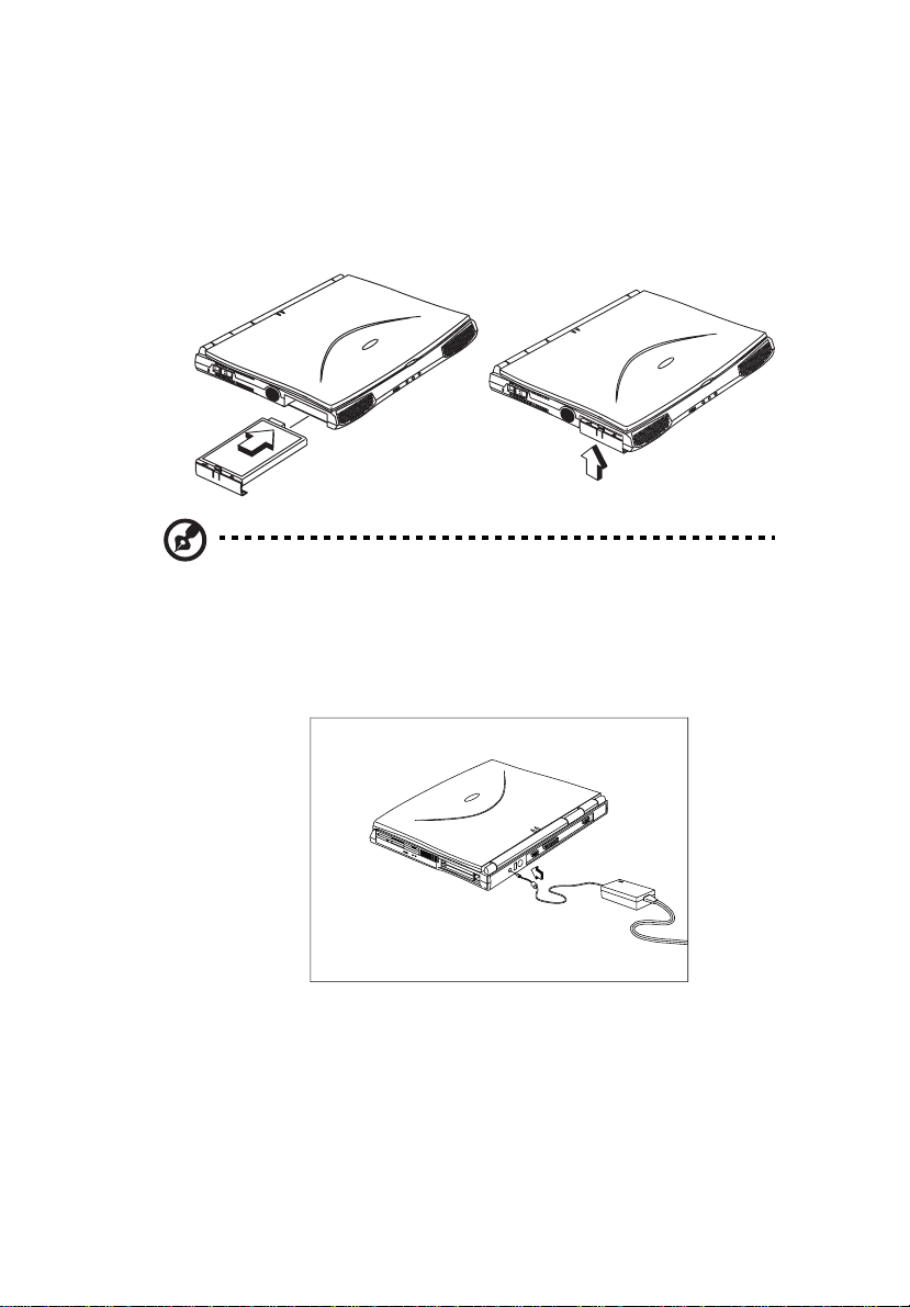
Connec tin g the comp ute r
Connecting the computer is as easy as 1-2-3.
1. Inser t th e ba ttery pack into the batte r y co m p ar tm e n t, then slide the batte ry
compartm ent cover in place.
Note
: When using a battery pack for the first time, fully recharge the battery,
then disconnect the adapter to use up the battery before recharging again.
Perform this action twice to condition the battery pack.
2. Con nect one end of the AC adapter to the DC-in port on the computer’s rear
panel and the other end to a properly grounded power outlet.
3. Slide the display cover latch to the left to open the display. Slide the power
switch towards the rear of the computer then release it to turn on the power.
Page 17

The POST (power-on self-test) routine then executes and Windows begins
loading.
Note
: To turn off the power, slide and hold the power switch for more than
four seconds. If you are using Windows 98, we recommend that you us e the
Shut Down command to turn off the computer. If you turn off the comp uter
and want to turn it on again, wait at least two seconds before powering up.
xvii
Page 18

xviii
Getting help and supp ort
This user’s guide provides clear and concise in formation about the computer, so
read it thoro ugh ly. T o pro vi de y ou wi th help whe n tra vel in g, th e co mput er al so ha s
a comprehensive online help.
Accessing online help
Follow these step s to ac ce ss the onl in e do cumenta tion:
1. Press the Windows logo button or click on the Start button.
2. Se lect Programs.
3. Click on TravelMate Online.
The online help is easy to navigate with hypertext and hypergraphics. Clear
illustrations help describe notebook operation as well.
Support information
Your computer is backed by an Int ernational Traveler’s Warranty (ITW ) that gives
you secur ity an d pe ace of mi nd whe n trav el in g. Our w orld wide net wor k of ser vi ce
centers are the re to give you a helping hand.
An ITW passp ort comes with your computer. This passport contains all you need
to know about the ITW prog ram. A l ist of ava ilabl e, aut hor i zed ser vic e ce nters are
in this handy booklet. Read this passport thoroughly.
Note
: Always hav e your I TW passport on hand, especially when you travel,
to receive the benefits from our support centers. Place your proof-ofpurchase in the flap located inside the front cover of the ITW passport.
If the country you are traveling in does not have an Acer-authorized ITW service
site, you can still get in contact with our offices worldwide.
For techn ical assistance and support in the Unite d States and Canada, you can call
1-800-81 6-2237. You can also contact a local dealer or distributor in the country
you ar e tr av eling in fo r as si stance.
To view support infor m ation, follow thes e steps:
1. Click on Start, Settings, Control Panel.
2. Double-click on System .
Page 19

3. Click on Support Information.
Note
: If you are connected to the Internet and have World Wide Web access,
visit our home page (www.acer.com/
worldwide o ffices, as well as information about our products.
xix
) and get an updated list of our
Page 20

xx
Care and ma in te na nc e
Taking care of your computer
Your computer will serve you well if you take care of it.
• Do not expos e th e compu te r to dir ec t sunl ig ht. Do not pla ce i t near sour ce s of
heat, such as a radiator.
• Do not expose the computer to temperatures below 0ºC (32 ºF) or above 50ºC
(122ºF).
• Do not subje ct the computer to magnetic fields.
• Do not expose the computer to rain or moisture.
• Do not spill water or any liquid on the computer.
• Do not subje ct the computer to heavy shock and vibration.
• Do not expose the computer to dust and dirt.
• Never place objects on top of th e computer to avoid dama ging the computer.
• Never place the computer on uneve n surfaces.
Taking care of your AC adapter
Here are some ways to take care of your AC adapter:
• Do not connect the adapter to any other device.
• Do not step on t he power cord or place heavy objects on top of it. Carefull y
route the pow er cord and any cables away from all potential traf fic.
• When unplugg in g th e powe r c ord , do not pul l o n th e cord i ts el f but p ull on t he
plug.
• The total ampere ratings of the equipment plugged in should not exceed the
ampere rating of the cord if you a re using an extension cord. Also, the total
current rating of all equipment plugged into a single wa ll outlet should not
exceed the fuse rating.
Taking care of your battery pack
Here are some ways to take care of your battery pack:
• Use only batteries of the same kind as replacements. Turn the power off
before removing or replacing bat teries.
• Do not tamper with batteries. Keep them away from children.
Page 21

• Disp ose of used ba tteries ac c or d in g to local regu lations . Re cy c le if at all
possible.
Cleaning and servicing
When cleaning the computer , follow these steps:
1. Power off the computer and remove the battery pack.
2. Di sconnect the AC adapter.
3. Use a soft cloth moistened with wate r. Do not use liquid or aerosol cleaners.
Contact yo ur dealer or see your service technician if any of the following occurs:
• The computer has been dropped or the body has been damaged.
• Liquid has been spilled into the product.
• The computer does not operate normall y.
xxi
Page 22

xxii
Page 23

1 Getting familiar with
your computer
Page 24

This computer combines high-performance, versatility,
power management features and multimedia capabilities
with a unique style and ergonomic design. Work with
unmatched productivity and reliability with your new
power computing partner.
This chapter gives an in-depth "tour" of the computer’s
many features.
Page 25

Features
This comput er was des igned wit h th e use r in mi nd. Here are jus t a few of its many
features:
Performance
• Intel® Celeron™ processor with 128 KB level 2 cache
• 64-bit /128-bit main memory
• Large LCD display and PCI video with 128-bit graphics acceler ation
• Internal CD-ROM drive
• Bui lt -in FDD mo d ule
• High-ca pacity, Enhanced-IDE hard disk
• NiMH battery pack
• Power management system with hibernation power saving modes
Multimedia
• 16-bit h igh-fidelity stereo audio with 3-D sound an d w avetable synthesizer
• Bui lt -in dual speakers
• Ultra-slim, high-speed CD-ROM drive
Connectivity
• High-speed fax/data software modem port
• USB (Universal Serial Bus) port
Human-centric design and ergonomics
• All-in-one design (CD-ROM, FDD, HDD)
• Sleek, smooth and stylish design
• Full-sized keyboard
• Wide and curved palm rest
• Ergonomically-centered touchpad pointing device
Expansion
• CardBus PC card (formerly PCMCIA) slot ( type II/I or type III) with ZV
Page 26

4
(zoomed video) port support
• Upgradeable memory and hard disk
1 Getting familiar with yo ur comp uter
Page 27

Display
The large graphics display offers excellent viewing, display quality and desktop
performa nce grap hic s. The compu te r suppor ts t wo dif f er ent d is pla y conf ig ur ation s
— High Performance Addressing (HP A) or Thin-Film Transistor (TF T).
Video performance
PCI video with 128- bi t graph ic s accel er ation and 2 MB video m emor y boost vide o
performa nce .
Simultaneous display
The computer’s large display and multimedia capabilities are great for giving
presentat io ns. If you pr ef er , you ca n also co nne ct a n exter nal moni tor w hen giving
presentations. This computer supports simultaneous LCD an d CRT display.
Simultaneous display allows you to control the presentation from your computer
and at the same time face your audience. You can also connect other output
displa y devices such as LCD project ion panels for large-audience presentations.
Power management
The power management system incorporates an "automatic LCD dim" feature that
automatically dims the LCD whe n the computer is power ed by a bat tery pack to
conserve battery power. See “Power management” on page 36 for more
information on power management features.
5
Opening and closing the display
To open the display, slide the di splay cover latch to the left and lift up the cover.
Then tilt it to a comfortable viewing position. The computer employs a
microswitch that turns off the dis play (and enters stan dby m ode) to conserve
power when you close the display co ver, and turns it back on when you open the
display cover.
Note
: If an external monitor is connected, the computer turns off the display
(but does not enter standby mode) when you clo s e the display cover.
To close the display cover, fold it dow n gently until the display cover latch cli cks
into place.
Page 28

6
Caution: To avoid damaging the display, do not slam it when you close it.
Also, do not place any object on top of the computer when the display is
closed.
1 Getting familiar with yo ur comp uter
Page 29
Indicators
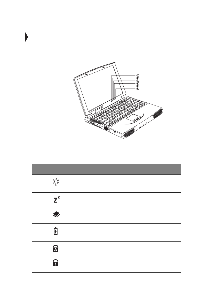
The computer has six easy-to-read status indicator s (LEDs) under the displ ay
screen.
The Power and Standby indicators are visible even when you close the display
cover so you can see the status of the computer while the cover is closed.
7
# Icon Function Description
1 Power Lights when the c o mputer is on.
Blinks when a battery-low condition occurs.
2 Standby Lights when the computer enters Stand by
3Media
Activity
4 Battery
Charge
5 Caps Lock Lights when Caps Lock is activated.
6Num Lock
(Fn-F11)
mode.
Lights when the floppy dr ive, hard disk o r CDROM drive is active.
Lights when the battery is b eing charged.
Lights when Numeric Lock is activated.
Page 30
8
1 Getting familiar with yo ur comp uter
Keyboard
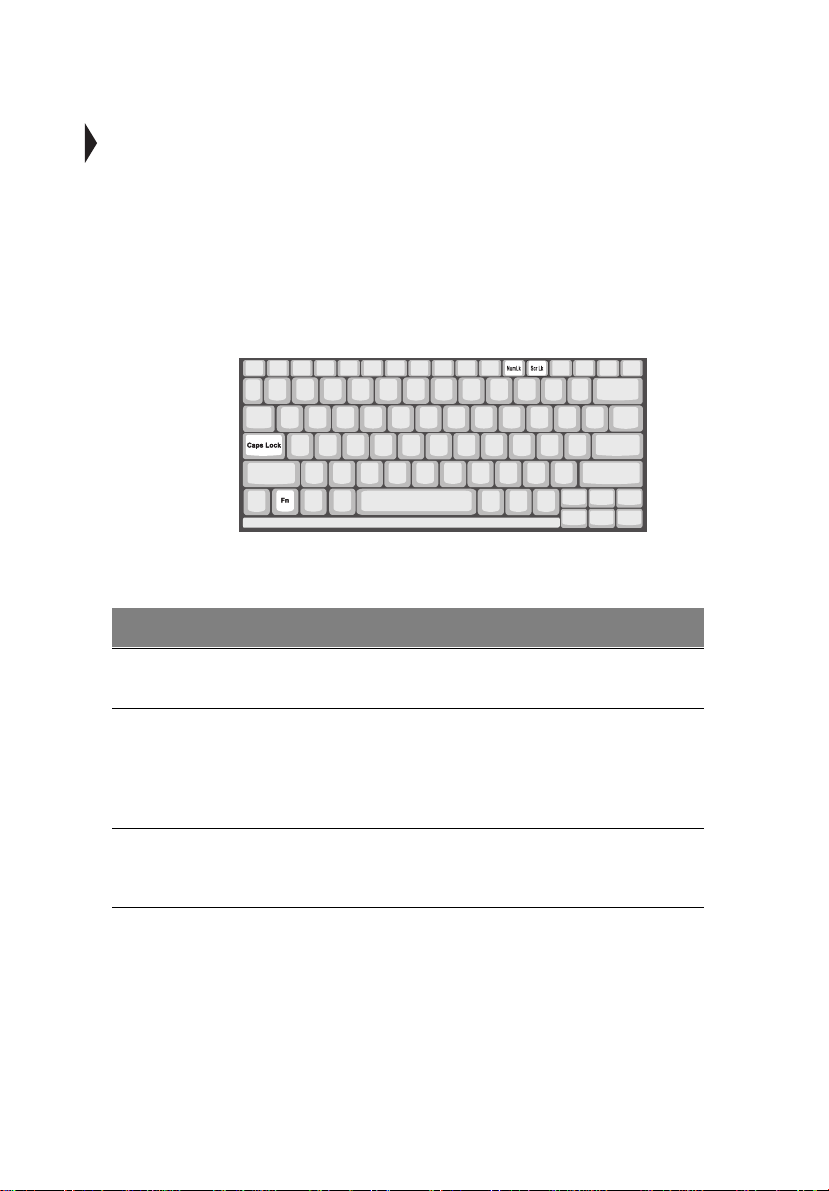
The keyboard has full-sized keys with an embedded keypad, separate cur sor keys,
two Windows keys and twelve function keys.
Spec ial keys
Lock keys
The keyboard has three lock keys which you can toggle on and off.
Lock Key Description
Caps Lock When Caps Lock is on, all alphabetic characters typed are in
Num Lock (FnF11)
Scroll Lock
(Fn-F12)
uppercase.
When Num Lock is on, the embedded keypad is in numeric mode.
The keys function as a calculator (complete with the arithmet ic
operators +, -, *, and /). Use this mode when you need to do a lot of
numeric data entry. A better solut ion would be to connect an
external keypad. See “External keyboar d” on page 44.
When Scroll Lock is on, th e screen moves one line up or down when
you pres s ↑ or ↓ respectively. Scroll Lock does not work with some
applications.
Page 31

Embedded numeric keypad
The embedded numeric keypad funct ions like a desktop numeric keypad. It is
indicated by small characters located on the upper right corner of the keycaps. To
simplif y the keyboard legend, cu rsor-control ke y symbols are not printed on the
keys.
Desired Access Num Lock On Num Lock Off
9
Number keys on
embedded key pad
Cursor-control keys on
embedded key pad
Main keyb oard keys Hold Fn while typing letters on
Note
: If an external keyboard or keypad is connected to the computer, th e
numlock feature automatically shifts from the internal keyboard to the
external keyboard or keypad.
Type numbers in a normal
manner.
Hold Shift while using cursorcontrol keys.
embedded key pad.
Hold Fn while using
cursor-control keys.
Type the letters in a
normal manner.
Page 32

10
1 Getting familiar with yo ur comp uter
Windows keys
The keyboar d has two ke ys that perform Windows-specific functions.
Key Description
Windows logo key Start button. Combinations with this key perform special
functions. Below ar e a few examples:
+ Tab (Activates next Taskbar button)
á
+ E (Explores My Computer)
á
+ F (Finds Document)
á
+ M (Minimizes All)
á
Shift + á + M (Undoes Minimize All)
+ R (Displays Run dialog box)
á
Appl ication ke y
(Fn-Application key)
Opens the application’s cont ext menu (same as right- click).
The Euro symbol
If your key board is in any of the following languages — United StatesInternational, United Kingdom, French, German, Italian, Spanish, Portuguese,
Page 33

Danish, Swiss Ge rman, Swiss French, C zech, Belgian, Norw egian, Hungarian,
Turki sh, Swedish or Finnis h — you can type the Euro symbol on your keyboard
Note
: Important! (for US keyboard users ) : The keyboard type is set when
you first set up W indows. For the Euro symbol to work, the keyboard type
has to be set to United States-International.
To verify the keyboard type:
1. Click on
2. Double-click on
3. Click on th e
Start, Settings, Control Panel
Keyboard
Language
.
tab.
.
4. Verify that the keyboard type used for "En English (United States)" is set t o
United States-International
5. If not, select and click on
International
and click on OK.
.
Propert ies
; then select
United States-
6. Click on OK.
To type the Euro symbo l:
1. Loc ate the Euro symbol on your keyboard.
2. Open a text editor or word processor.
3. Hold
Alt Gr
and press the Euro symbol.
11
Note
software do not support the Euro symbol. Please refer to
(
Alt Gr
:The
www. microsoft.com/typography/faq/faq12.htm
is only used together with the Euro symbol. Some fonts and
)
for more information.
Page 34

12
1 Getting familiar with yo ur comp uter
Hotkeys
The computer employs hotkeys or key combinations to acces s m o st of the
computer’s controls like screen contrast and brightness, volume output and the
BIOS setup utility.
HotKey Icon Function Description
Fn-F1 Hotkey help Displays a list of the hotkeys and their
Fn-F2 Setup Accesses t he notebook configurat ion
Fn-F3 Power Scheme
Toggle
Fn-F4 Sleep Puts the computer in Sleep mode, which
Fn-F5 Display toggle Switches display output between the
Fn-F6 Screen blan k Turns the display screen backlight off to
functions.
utility. See “Notebook Manager” on page
71.
Switches betw een the different Power
Management schemes.
can be def ined via the advanced section of
the Power Management Propertie s in the
Windows Control Panel.
display screen, external monitor (if
connected) and both the display screen and
external monitor.
save powe r. Press any key to re turn.
Page 35
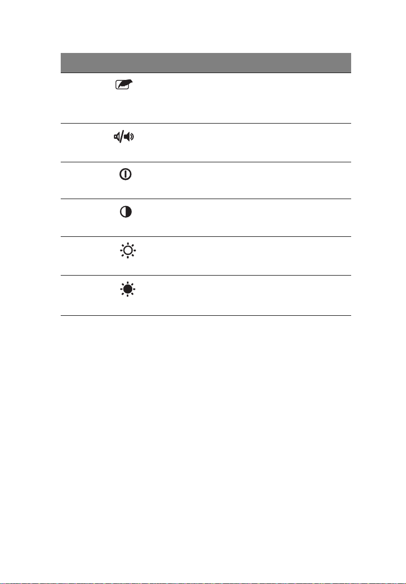
HotKey Icon Function Description
13
Fn-F7 T ouchpad on/
off
Fn-F8 Speaker on/off Turns the speakers on and of f ; mutes the
↑
Fn-
Fn-
Fn-
Fn-
↓
→
←
Contrast up Increases the screen contrast (available
Contrast down Decreases t he s creen contrast (available
Brightness up Increases the scre en br ightness.
Brightness
down
Tur ns the internal touchpad on and off.
When you co nne ct an e xt ernal P S/2 m ouse,
the computer automatically disables the
touchpad.
sound.
only for models with HPA displays).
only for models with HPA displays).
Decreases t he s creen brightness.
Activating hotkeys
When activating hotkeys, pr ess and hold the first key Fn before pressing the other
key in the hotkey combination.
Page 36

14
1 Getting familiar with yo ur comp uter
Keyboard ergonomics
Located be low the keyboard, the wide and curved palm rest is ergonomically
designe d to provide you with a very comf ortable place to rest your hands whil e
you type.
Page 37

Touchpad
The built-in touchpad is a PS/2-com patible pointing device that senses movement
on its surface. This means the cursor responds as you move your finger on the
surfac e of the touchpad. The centr al location on the palm rest pr ovides optimum
comfort and support.
Note
: When you conn ect an external PS/2 mouse, the computer
automatically disables the internal touchpad.
Touchpad basics
The follow ing item s teach you how to use the touchpad:
• Move your finger across the touchpad to move the cursor.
• Press the left and right buttons located on the edge of the touchpad to do
select ion and execution functions. These two butt ons are similar to the left
and right bu ttons on a mouse. T apping on the touchpad produces similar
results.
15
Function Left Button Right Button Tap
Execute Click twice
quickly
Select Click on ce Tap once
Tap twice (at the same speed as
double-clicking the mouse button)
Page 38

16
Function Left Button Right Button Tap
1 Getting familiar with yo ur comp uter
Drag Click and
hold, then
use finger to
drag the
cursor on the
touchpad
Access
context menu
Note: Keep your finger s dry and clean when using the touchpad. Also keep
the touchpad dry and clean. The touchpad is sensitive to finger movements.
Hence, the lighter the touch, the better the response. Tapping too hard will
not increase the touchpad’s responsiveness.
Tap twice (at the same speed as
double-clicking the mouse button)
and hol d finger to the touchpad on
the second tap to drag the cursor
Click once
Page 39

Storage
This comput er supplies you with all-in -one media storage:
• High-cap acity Enhanced-IDE hard disk
• Standard ultra-slim internal 3.5-inch floppy drive
• High-spe ed ultra-slim CD-ROM drive
Hard disk
The hard dis k can be upgraded when you need more storage space. Consult you r
dealer for details.
Floppy drive
The ul tr a- slim internal flop py dr ive reads and writes on standa r d 3.5-inch
diskettes.
Ejecting a floppy disk
Press the floppy disk eject button to eject a floppy disk from the floppy drive.
17
CD-ROM drive
A high-speed CD-ROM drive gives yo u p ortable multime dia acc ess.
Page 40

18
1 Getting familiar with yo ur comp uter
Ejecting the CD-ROM tray
To eject the CD-ROM dri ve tray when the compute r is turned on, press t he C D ROM ej ec t bu tton.
Note: When power is off, you can eject the CD-ROM drive tray usin g the
emergency eject hole (see page 93).
Page 41
Ports
Ports allow you to connect peripheral devices to your computer as you would with
a desktop PC
Note
: See Chapter 3 on how to connect external devices to the computer.
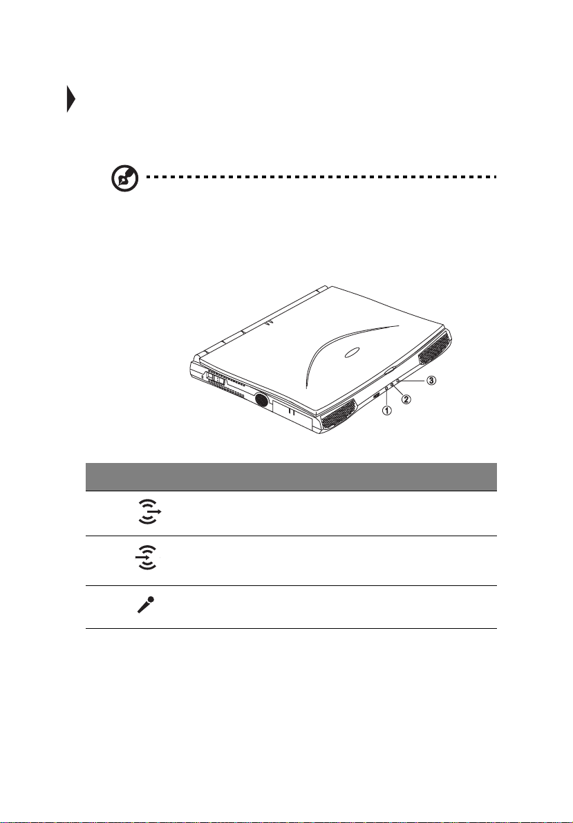
Front ports
The front panel contains ports for external audio connections.
19
# Icon Port Connects to...
1 Speaker-out jack Speake r s or headphones
2 Audio line-in
jack
3 Microphone-in
jack
Audio line-in device with a 3.5mm minijack
(e.g., audio CD player, stereo walkman)
3.5mm minijack condenser microphone
Page 42

20
1 Getting familiar with yo ur comp uter
Rear ports
# Icon Port Connects to...
1 DC-in jack AC adapter and pow er outlet
2 USB port USB devices (e.g., USB mouse)
3 PS/ 2 port PS/2- c om p a t ible devi ce s ( e. g., PS/2
4 Serial port Serial devices (e.g., serial mouse)
5 Parallel port Parallel devices (e.g., parallel pr inter)
6 External monitor
port
keyboard/mouse/keypad)
Display monitor (up to 1024x768
resolution, 64K-colors)
Universal Serial Bus
The Universal Serial Bus (USB) port is a high-speed serial bus which allows you
to connect and daisy-chain USB peripherals without taking up precious system
resources.
Page 43

Right ports
# Icon Port Connects to...
1 PC Card slot 16-bit PC Cards and 32-bit CardBus
21
PC Cards (ZV support)
2 Modem jack Phone line ( only for models with an
internal fax modem)
PC card slot
There is one type II/I or one type III CardBus PC card s lot found on the right panel
of the computer. This slot accepts credit-card-sized cards that enhance the
usability and expandability of the computer.
PC cards (form erl y PCMCI A) ar e add-o n car ds f or po rtabl e co mput ers , givi ng yo u
expansi on possibilities long afforded by desktop PCs. Pop ular type II cards
include flash memory, SRAM, fax/data modem, LAN and SCSI cards. Common
type III cards are 1.8-inch AT A drives and cellular modems. CardBus improves on
the 16-bit PC card technology by expa nding the data path to 32 bits.
ZV (zoomed vi de o) p ort s uppo rt al lo ws yo ur compu te r to su ppo rt har dwar e MP EG
in the form of a ZV PC card.
Note
: Refer to your card’s manual for details on how to insta ll and use the
card and its functions.
Page 44

22
1 Getting familiar with yo ur comp uter
Inserting a card
Insert the card into the s lot and make the proper connections (e.g., network cable),
if necessary. See your ca rd manual for details.
Ejecting a card
Before ejecting a PC card:
• Exit the application using th e card.
• Left-click on the PC card icon on the taskbar and stop the card operation.
Press the slot eject button once to pop it out; then press it again to eject the PC
card.
Fax/data modem
The computer has a built-in fax/data modem (available in select countries)
Caution: This modem port is not compatible with digital phone lines.
Plugging thi s modem into a digital phone line wil l damage the modem.
Page 45

To use the fax/data modem port, connect a phone cable from the modem port to a
telephone jack.
23
Page 46
24
1 Getting familiar with yo ur comp uter
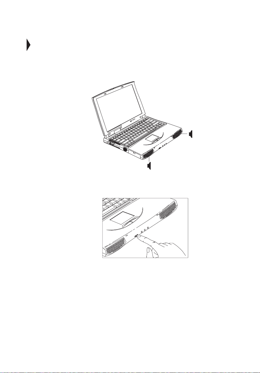
Audio
The standard computer configuration includes 16-bit high-fidelity stereo audio
with fur ther enhancements that include 3D sound for true audio immersion. Front
dual speakers direct sound towards you to further enhance sound output.
Use the volu me cont ro l knob to ad jus t the vol ume l eve l. Turn t he kno b to th e right
to increase the vol um e ; tu rn it to the left to dec r ea se the volum e .
Page 47

Securing your computer
Security features include hardware and softwar e locks — a security notch and a
two-le vel passwo rd scheme .
Security notch
A securit y notch located on the re ar panel of the computer l ets you connect a
Kensingt on-compatible key- based computer security lock.
Wrap a computer security lock cable around an immovable object such as a table
or locked drawer handle. Insert the lock into the notch and turn the key to secure
the lock.
25
Passwords
A two-level password scheme protects your computer from unauthorized access.
When set, no one can access the computer without entering the correct password.
There are two types of passwords you can set:
• Supervis or Pass w ord sec ures your computer against unauthorized entry to
and use of the BIOS Utility.
• User Password secures your computer against unauthorized use.
See “BIOS Utility” on page 79 for details.
Important
need to contact your dealer.
: Do not forget your password! If you forget your password, you
Page 48

26
Setting a password
You can set the passwo rd using:
• Notebook Manager — go to page 75.
• BIOS Utility — go to page 86 .
1 Getting familiar with yo ur comp uter
Page 49

27
Page 50

28
1 Getting familiar with yo ur comp uter
Page 51

2 Operating on
battery
Page 52

The computer operates on AC or battery power. This chapter
contains the information you need to know to operate the
computer on battery power. It also includes information on
how your computer manages and saves power.
Page 53

31
2 Operating on battery power
power
Page 54

32
2 Operating on battery power
Battery pack
The computer uses a battery pack that gives you long use between charges.
Battery pack characteristics
The batte ry pack has the following characteristics:
• Employs current battery te chnology standards
• Battery-low warning
When the battery charge level becomes low, the status indicator of the
computer flashes at regular inte rvals. This tells you that the battery power is
critical l y low ( and yo u sho uld save your work ). You can corre ct thi s si tuat io n
by recharging the battery pack.
Whenever pos si ble, use th e AC adapt er. The battery wil l come in han dy when you
travel o r during a power failure. It is advisable to have an extra fully-charged
battery pack available as back up.
Using a battery pack for the first time
When using a battery pack for the first time, follow these steps:
1. Connect the AC adapter to a power source and to the computer and fully
recharge the battery.
2. Di sconnect the adapter to use up the battery before recharging again.
You only need to do this once or twice with a new battery or with a battery that's
been stor ed w ithout being used for a long time. If the co mp uter is to be stored for
more than two weeks , w e suggest you remove the battery pack. Batter y pow er
from a full y charged battery pack depletes in roughly a day with the computer in
Standby mode, a month in Hibernation m ode or when power is off.
Warning! Do not expose battery packs to temperatures below 0ºC (32ºF) or
above 60ºC (140ºF). This may adversely aff ect the battery pack.
Installing and removing the battery pack
Important! Before removing the battery pack, make sure that you have an
AC adapter connected to the computer; otherwise, turn off the computer.
Page 55
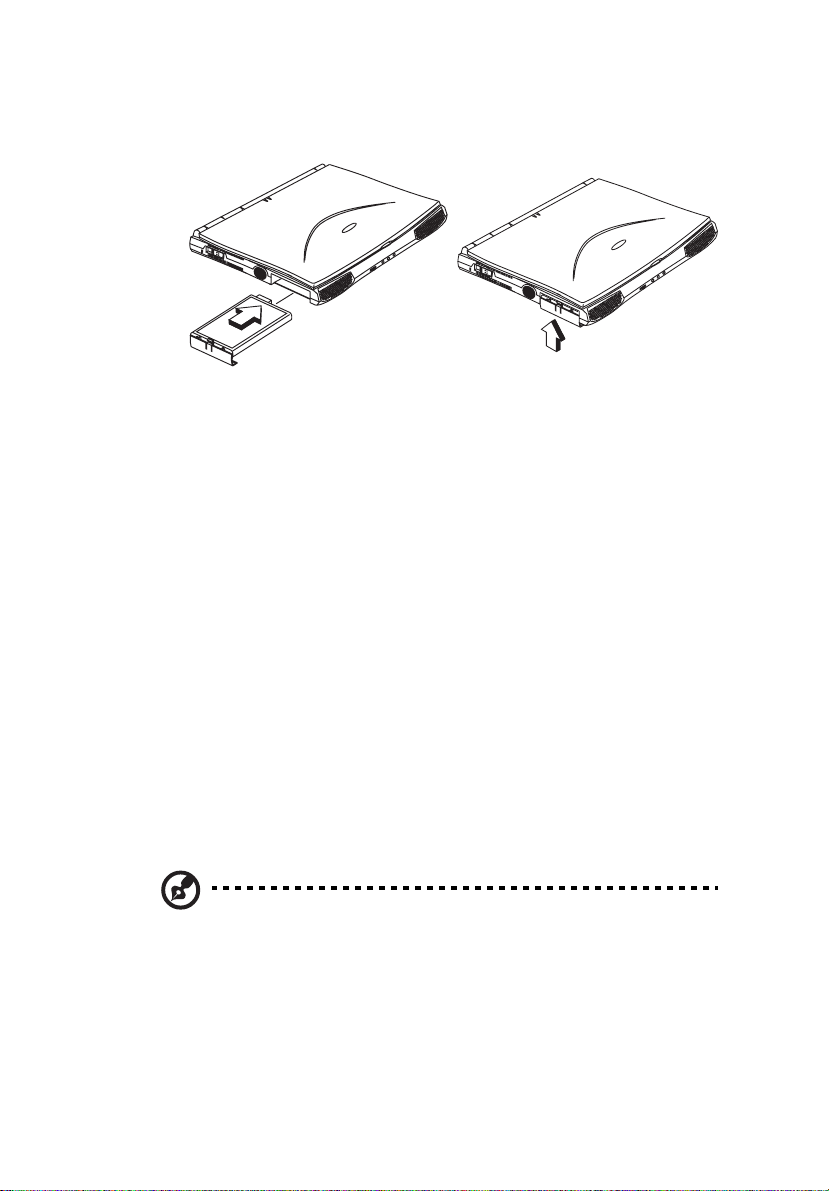
To install a battery pack, slide it into the battery compartment, then latch the
battery compartment cover.
Reverse the procedure to remove the battery pack.
Charging the battery
To charge the battery, slide the battery pack into the battery bay and plug the AC
adapter into the computer and an electrical outlet.
Charging modes
The adapter has three charging modes:
•Rapid mode
The computer uses rapid charging when power is turned off and a powered
AC adapter is connected to it. In rapid mode, a fully depleted battery gets
fully charged in approximately two hours.
•Charge-in-use mode
When the computer is in use with the A C adapter plugged in, the computer
also charges the bat t e ry pa ck if installe d. Thi s m od e wi ll take longe r to ful ly
charge a battery than rapid mode. In charge-in-use m ode, a fully depleted
battery gets fully charged in approximately 4 hours.
33
Note
: We suggest that you charge the b attery pack before r etiring for the day,
letting it charge overnight before tr aveling. This ensures a full y charged
battery for use the next day.
Page 56

34
2 Operating on battery power
Checking the battery lev el
Using the Window s battery meter
The Windows battery meter indicates the present battery level. Simply rest your
cursor on the battery meter (or AC plug) icon on the taskbar to see the present
charge level of your battery.
Optimizing battery life
This section helps you get the most out of battery operation. Optimizing battery
life prolongs the charge/recharge cycle and improves recharge ef ficiency. Follow
these sug gestions to optimiz e and maximize battery power:
• Pur c ha s e an extra ba tt er y pack.
• Use Sleep Manager to reserve har d disk space for the Hibernation function.
See “Sleep Manager” on pa g e 66.
• Use the AC ad apter whenever possible so that the batt ery is reserved for onthe-go co mp uting.
• Keep the battery pack in the computer powered by the AC adapter. The
constant trickle charge maintains the battery level to eliminate the battery
self-d ischarge effect. The charge-in-use function als o charges the batte ry
pack.
• Disable the pa rall el and seri al por ts if no d evi ces ar e c onn ect ed to the se por ts.
You can do this through the Setup Utility. See “Onb oard Device
Configuration” on page 84.
• Eject the PC card from the card slot when it is not in use, since the PC card
draws extra power. See “Ejecting a card” on page 22.
• Store the battery pack in a cool, dry place. The recommended storage
temperature for battery packs ranges from 10 to 30 degrees Celsius. The
higher the storage temperatu re, the faster the battery pack self-discharges.
• The batte ries can be recharged about 400 times when used as directed.
Excessiv e recharging decreases battery life.
• Take care of your battery pack and AC adapter. See “Care and maintenance”
on page xx of th e preface.
Page 57

Battery-low warning
You never have to worry about battery power as long as you are using the AC
adapter. However, when you operate the computer on battery power, pay extra
attention to the power indicator on th e display panel.
The following signal indic ates a battery-low condition:
• The po w e r indicato r fla sh es at regular intervals until ba tt ery power is
depleted.
35
Warning!
is lost when computer power is cut off during Standby mode.
Connect the AC adapter to the comput er as soon as possible. Data
The follow ing tab le shows the recommended course of action to take when you
encounter a battery-low co ndition.
Situation Recommended Action
AC adapter and power
outlet ava ila ble
An extra fully-charged
battery pa ck available
AC adapter or power
outlet not available
1. Connect the AC adapter to the computer.
2. Save all necessary files.
3. Resume work.
Power off the computer if you wish to recharge th e battery
rapidly.
1. Save all necessary files.
2. Exit the applica tio n .
3. Po w e r off t h e computer.
4. Replace the battery pack.
5. Power on the computer and resume work.
1. Save all necessary files.
2. Exit the applica tio n .
3. Po w e r off t h e computer.
or
1. Save all necessary files.
2. Enter Sleep mode (press Fn-F4).
Page 58

36
2 Operating on battery power
Power management
This comput er has a bui lt-in powe r mana gement un it that m onitors system act ivit y .
System activity refers to any activity involv ing one or more of the following
devices : keyboard, mouse, floppy drive, hard disk, peripherals connected to the
serial and parallel ports , and video memory. If no activity is detected for a period
of time (called an inactivity timeout), the computer stops some or all of these
devices in order to conserve energy.
This comput er employs a power management scheme that supports ACPI
(Advanced Configuration and Power Interf ace) which allows for maximum power
conserv ation and maximum perform ance at the same time. Windows handles all
power-saving chores for your computer.
Advanced Configuration and Power Interface
Advanced Configuration and Power Interface (ACPI) is a pow er management
specification jointly developed by Intel, Microsoft, and T oshiba. ACPI enables
Windows to control the amount of power given to each device attached to the
computer. With ACPI, Window s can turn of f peripheral devices when they are not
in use, thereby saving power.
Note: We re commend y ou en able p ower mana gement to pr olon g yo ur ba ttery
life.
Power management modes
Sleep mode (ACPI)
If ACPI i s installed, all power management functions are handled by the Windows
operating system.
Sleep mode may be one of three computer power-saving modes: Standby,
Hibernation or power off.
To enter Sleep mode under ACPI:
• Press the Sleep hotkey
• Allow the id le tim es for de vic es and the co mp uter det er mine d by W indow s 98
to elap se
Fn-F4
Page 59

How to exit Sleep mode depends upon which power -saving mode the computer is
in.
Display standby mode
Screen act ivity is determined by the keyboard, the built-in touchpad, and an
externa l PS/2 pointing device. If these devices are idle for the period specified by
the LCD backli ght Timeout value, the display shuts off until you press a key or
move the touchpad or external mou se.
"Automatic dim" feature
The computer has a unique "automatic dim" power-saving feature. When the
computer is using AC power an d you disconnect the AC adapter from the
computer, it automati cally dims the LCD backlight to save power. If you
reconnect AC power to the computer, it automatically adjusts the LCD backlight to
a bright er level.
Hard disk standby mode
The hard dis k enters standby mode when there are no disk read/write operations
within the period of time determined by the power management system. In this
state, the power supplied to the hard disk is redu ced to a minimum. The hard disk
returns to normal once the computer accesses it.
37
Standby mode
The compu ter consumes very low power in Standby mode. Data remains intact in
the system memory until the battery is drained.
There are four ways to enter Standby mode:
• Pressi ng the Sleep hotkey Fn-F4
• If the waiting time specified by the Standby Tim eout value or the operating
system elapses without any sy stem activity
• Closing t he display cover
• When the com puter is about to enter Hibernation m ode (e.g., during a battery
low condition), but the Hibernation file is inv alid or not present
Note
: If the compu ter does not enter Standby mode after pressing the Sleep
hotkey , i t means the o perati ng sy stem w ill not allow the co mputer t o enter t he
power-saving mode.
Page 60

38
2 Operating on battery power
The follow ing sign als indicate that the computer is in Standby mode:
• The buzzer beeps (when the hotkey is pressed to enter into Standby mode)
• The Standby indicator lights
Warning! Unstored data is lost when you turn off the computer power in
Standby mode or when the battery is drained.
To leave Standby mode and r eturn to normal mode:
• Press any key
• Have the Resume Ti mer set and let it be matched
• Open the display cover
• Experienc e an in co m ing PC card mo d em event
Hibernation mode
In Hibernation mode, all power shuts off (the computer does not consume any
power). The comput er save s all system information onto the hard dis k before it
enters Hibernation mode. Once you turn on the power, the computer restores this
information and resumes right where you left off before entering Hibernation
mode.
Before th e com puter can enter Hibernation mode, the Hiber nation file created by
Sleep Manager must be present and valid. See “Sleep Manager” on page 66.
Then, the re are three ways to enter Hibernation mode:
• Pressing the Sleep hotkey
Fn-F4
• If the waiting time specified by the Hibernation T im e out value elapses
with ou t an y system activity
• Invoked by th e operating system power-saving modes
Note: If the computer beeps but does not enter Hibernation mode after
pressing th e Hiber nati on hotk ey , it mean s the oper ati ng system w ill not all ow
the computer to enter the power-saving mode.
To exit Hibernation mode, press the power swi tch. The computer also resum es
from Hibernation mode if the Resume Timer is set and matched.
Page 61

39
Warning!
computer is in Hi bernation mode.
Do not change any devices (such as add memory) when the
Page 62

40
2 Operating on battery power
Page 63

3 Peripherals and
options
Page 64

Your computer offers excellent expansion
capabilities with its built-in ports and connectors.
This chapter describes how to connect peripherals
and hardware options that help you us e your
computer with ease. When connecting peripherals,
read the manual included with the peripheral for
operating instructions. You can purchase most of
these and other options directly from Acer .
This chapter also includes sections on how to
upgrade key components. Key component
upgradeability helps keep your computer in step
with the latest technology.
Page 65

External monitor
To show graphical effects on a larger display, connect an external monitor to the
CRT port. Read th e m o nitor manu al for additional instructions.
Note
: If an external monitor is not connected, closing the display cover puts
the computer into Standby mode.
Using simultaneous display
43
Your compu ter takes advantage of Windows 98 multi-display capability, allo w ing
you to use your computer for prese ntation purposes. So whate ver is displayed in
your computer will likewise be displayed on the other output display.
To use simultaneous display, you can choose to connect othe r output display
devices to the computer through t he CRT port.
Enabling simultaneous display
To enable and set simul taneous display options, follow these steps:
1. Click on
2. Click on
3. Click on th e
4. Click on
5. Click on
6. Click on OK.
Start, Program
Notebook Manager
Both
Both
Display Device
under the Boot Display Device.
under the Switching Display Device.
Notebook Manager
, then
.
tab.
.
Page 66

44
3 Peripherals and options
External keyboard
This computer has a keyboard with full-sized keys and an embedded keypad. If
you feel mor e comfortable using a des ktop keyboard, you can i nstall a PS/2compatible external keyboard.
To connect an external keyboard, plug the external keyboard into the PS/2
connector.
Page 67

External keypad
You can also use a 17-key numer ic keypad for number-sensitive, data-en try
applica tions. To connect the keypad , plug the keypad c onnector into the PS/2 port.
45
Page 68

46
3 Peripherals and options
External pointing device
This comput er acc ept s e ithe r a PS /2- comp atib le or seri al mous e or si mil ar pointi ng
device.
Note: When using an external mouse, you may choose to disabl e the internal
touchpa d by pressing Fn-F7.
External PS/2 mouse
The built-in touchpad works alt ernately with an external PS/2 mouse which is hotpluggable. To use a PS/2-compatible mouse, simply pl ug it into the PS/2 port.
External serial mouse
If you use a se rial mouse, plug it in to the serial port.
To enable the serial mouse, use the Add New Hardwa re tool in the Windows
Control Panel.
Page 69

Printer
This comput er suppo rts both serial and parallel printers. For a seria l printer, plug
the printer cable into the serial port. For a parallel printer, plug the printer cable
into the p arallel port. See your printer manual for operating instru ctions.
Note
: If the printer does not function, enter Setup and verify that the parallel
port is enab led. See “Onboard Device Configuration” on page 84 for
assistance.
47
Page 70

48
3 Peripherals and options
Audio devices
Audio devices are easy to connect with the audio port s accessible from the front o f
the comput er. Y o u can pl ug an e xter nal mic ro phone i nt o th e micr opho ne- in ja ck or
an audio line-in device into the audio line-in jack. Amp lified speakers or
headphone s connect to the speaker/headphone-out jack.
Page 71

PC cards
The computer has one Car dBu s PC card sl ot that ca n acc ommoda te one ty pe II/ I or
one type III PC card. Please consult your dea ler for PC card options available that
you can purchase for your computer.
49
Page 72

50
3 Peripherals and options
USB devices
The computer has a USB (Universal Serial Bus) port that allows you to connect
peripherals without occupying too many resources. Common USB devices
include the mouse and keyboard.
Most USB devices also inc lude a built-in U SB port connector w hich allows you t o
daisy-c hain other USB devices.
Page 73

Miscellaneous options
Additional power packs
You can order an AC adapt er and sp are batteries.
Battery pack
It is a good practice to have a spare b attery around, especially when you travel.
The NiMH battery, coupl ed w ith the power management features of your
computer, supplies you with more power on-the-go.
AC adapter
The compact AC adapt er charges your battery pac k and supp lies power to your
computer. You can or der a spare AC adapter so you do not need to carry it from
the office to your home or destination.
Cables
PS/2 Y-bridge cable
51
The PS/2 Y-br idge cable allows you to simultaneously connect two PS/2 devices,
a mouse and a keyboard, to your computer.
Note
: The keyboard must be connected to the connector marked keyboard
and the mouse must be connect ed to the connector marked mouse .
Page 74

52
Connect t he singl e c onne ctor end of the Y-b ridge cab le to the co m puter’s PS/2 port
and the double connector ends to the two PS/2 devices.
3 Peripherals and options
File transfer cable
Besides us ing the infrared port, you can also transfer files between computers
using a file transfer cable. Connect the file transfer cable between the parallel
ports of the two co mputers and use your fil e transfer utility to perform the transfer.
Page 75

Key component upgrades
Your computer delivers superior power and performance. However, some us ers
and the applications they use may demand more. This computer allows you to
upgrade key components when you need increased performance.
Note
: Contact your author ized dealer if you decide to per form a key
component upgrade.
Memory upgrade
The noteboo k com p uter comes with eith er 32 MB or 64 MB onboard system
memory wit h one DIMM socket for upgrade use. It supports 32-/64-/128 MB 64bit/128-bit Synchronous Dynamic Random Access Me m ory (SDRAM) soDIMMs
(Small Outline Dual Inline Memory Modules).
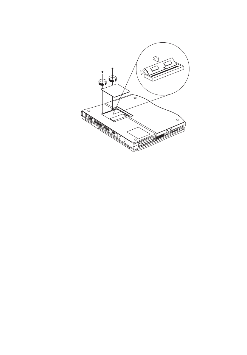
Installing memory
Follow th ese steps to in st al l m em o ry:
1. T urn off the compu ter, unplug the AC adapter (if connected) and remove the
battery pack. Then turn the computer over to access its base.
2. Remove the screws from the memory door; then lift up and remove the
memory door.
3. Insert the memory module diagonally into the slot, then gently press down
until i t clicks into place.
53
Page 76
54
4. Replace the memory door and secu re it with the screws.
The computer automatically detects and reconfigures the total memory size.
3 Peripherals and options
Hard disk upgrade
It is possi bl e to upgr ad e you r ha rd disk wit h a hi gher ca pac it y dri ve whe n you need
more storage space. The computer uses a 9.5mm 2.5-inch Enhanc ed-IDE hard
disk. Please cons ult your dealer if you need to upgrade your hard disk.
Page 77

4 Moving with your
computer
Page 78

This chapter gives you tips and hints on things to
consider when moving around or traveling with
your computer.
Page 79

Disconnecting from the desktop
Follow these steps to disconnect your computer from external accessories:
1. Sa ve your work in progress.
2. Shut down the operating system .
3. T urn off the compu ter.
4. Di sconnect the cord from the AC adapter.
5. Di sconnect the k eyboard, pointing device, printer, e xternal monitor, and other
externa l devices.
6. Di sconnect the Kensingt on lock if you are using one to secure the computer.
57
Page 80

58
4 Moving with your compu ter
Moving around
when you are just moving within sho rt distances, for example, from your office
desk to a meeting room
Preparing the computer
Before movi ng the computer, cl ose and latch the display cover to place it in
Standby mode . You can now safel y ta ke th e compu te r anywher e yo u go wit hi n the
building.
To bring the computer out of Standby mode, open the display.
What to bring to short meetings
A fully char ged ba tt er y runs th e comput er for 2-3 hours unde r most cir cums tance s.
If your meet ing is shorter than th at, you probably do not need to bring anything
with you other than the computer.
What to bring to long meetings
If your meeting will last l onger than 3 hours or if your battery is not fully charged,
you may want to bring the AC adapter wit h you to plug in your computer in the
meeting room.
If the meeting room does not have an electrical outlet, reduce the drain on the
battery by putting the c o m puter in standby m ode. Press Fn-F3 or close the display
cover when eve r you ar e not ac tivel y us in g the co mput er. Then tap any ke y or o pen
the display to resume.
Page 81

Taking t he computer home
when you are moving from your office to your hom e or vice versa
Preparing the computer
After d isconnecting the computer from your desktop, follow these steps to prepare
the computer for the trip home:
1. Remove all media from the drives. Failure to remov e the medi a can damage
the driv e head.
2. Pa ck the computer in a protective case that ca n prevent the computer from
sliding around and cushion it if it should fall.
Caution
: A void packing items next to the top cover of t he computer.
Pressure aga inst the top cover could damage the screen.
What to bring with you
Unless you already have some items at home, bring the following it em s with you:
• AC adapter and power cord
• The printed user’s manual
59
Special considerations
Follow these guidelines to p rotect your computer while traveling to and from
work:
• Mini m iz e the effect of te m p erature ch a n ges by keepi ng the compu te r w ith
you.
• If you need to stop for an extended per iod of tim e and cannot bring the
computer with you, leave the computer in the trunk of the car to avoid
exposing the computer to excessive heat.
• Changes in temperature and humidity ca n cause condensation. Allow the
computer to return to room temperature, and inspect the screen for
condensation before turning on the com p uter. If the temperature change is
greater than 18°F (10°C), allow the computer to come to room temperature
slowly. If possibl e, l eav e the c om puter fo r 30 minu tes i n an e nvi ronm ent wi th
a temperat ure between outside an d room temperature.
Page 82

60
4 Moving with your compu ter
Setting up a home office
If you frequently work on your computer at home, it may be worthwhile to
purchas e a seco nd AC adap ter f or u se at h ome. W i th a second AC adapt er, you can
avoid transporting the extra w eight to and from home.
If you use you r computer at home for significant periods of time, you might also
want to add an external keyboard, monitor, or mouse.
Page 83

Traveling with the computer
when you are moving within a larger distance, for instance, from your office
buildi ng to a client’s off ice building or trav eling locally
Preparing the computer
Prepare the computer as if you were taking it home. Be sure the battery in the
computer is char ged. Airport security may require you to turn on your comp uter
when bringing it into the gate area.
What to bring with you
Bring the follow in g items with yo u:
•AC adapter
• Spare, f ully charged battery packs
• Add itional pr in te r d river files i f yo u pla n to use anothe r printer
Special considerations
61
In addition to the guidelines for taking the com puter home, fol low these guide lines
to protect your computer while traveling:
• Always take the computer as carry-on luggage.
• If possible, have the computer inspected by hand. The computer can safely
pass through security X-ray machines, but never expose the computer to a
metal de te c t o r.
• Avoid exposing floppy disks to hand-held metal detectors.
Page 84

62
4 Moving with your compu ter
Travelin g internationally with the computer
when you are moving from country to cou ntry
Preparing the computer
Prepare the computer as you would normally prepare it for traveling.
What to bring with you
Bring the follow in g items with yo u.
•AC adapter
• Power cords that are appropriate to the country to which you are traveling
• Spare, f ully charged battery packs
• Additional printer driver files if you plan to use another printer
• Proof of purchase, in case you need to show it to customs offi cials
• International Traveler’s Warranty passport
Special considerations
Follow the same sp ecial considerat ions as when traveling with the computer. In
additi on, these tips are useful when traveling internationally.
• When traveling in another country, check that the local AC voltage and the
AC adapte r power cord specif ications are compatible. If not, purchase a
power cord that is compat ible with the local AC voltage (e.g., power rating).
Do not use converter kits sold for appl iances to power the com puter.
• If you ar e using the modem, check if the modem and connector is compatible
with the t e lecom system of the country you are traveli ng in.
Page 85

5 Software
Page 86

This chapter discusses the important system utilities
bundled with your computer.
Page 87

65
5 Software
System software
The computer comes preloaded with the following software:
• Windows operating system
• DMI (Desktop Management Interface)-compliant hardware BIOS utility
• System utilities, drivers and application software
Note: To acc ess W indows so ftware ap pli catio ns, clic k on the S tar t butto n and
select the app li cation folder. Then click on the application ic on to run the
selected application. To learn about the software and utility, make use of the
online help provided by the software.
Page 88

66
5 Software
Sleep Manag er
Most notebook computers fea ture built-in pow er-saving functions. This computer
has two power management modes, Standby and Hibernation.
While Stan dby pu ts your compu te r in to a li ght sleep s ta te, Hib er nat ion shu ts of f all
power aft er sav ing the current state of your computer. The next time you slide the
power switch, the computer resumes from where you left off.
Sleep Manager allows your computer to perform these power-saving functions.
Note: See “Power management” on page 36 to understand how your
computer saves and man ages power.
Sleep Manager is a utility that works with your computer’s BIOS and Windows
APM (Advanced Power Management) to manage the Hibernation operation. This
includes:
• creating the Hibernation file which contains the current state of the computer
• checking if the Hib e rn a tio n file is valid
• saving an d loadi ng the conten ts of t he Hiber na ti on fil e whe n en te ring i nt o and
resuming from Hibernation mode
The Hibernation file resides in a contiguous area on you r hard disk.
Sleep Manager can automatically create, recover, and reallocate space for the
Hibernat ion file. If the system memory size changes or the Hibernation fi le on the
hard disk is corrupted, Sleep Manager reallocates the ha rd disk space for you
automatically.
Accessing the Sleep Manager
There are tw o w ays to bring up the Sleep Manager.
• On the taskbar
The computer automatically loads Sleep Manager every time you start
Windows. Sleep Manager resides in the background and the Sleep Manag er
status icon appears on the taskbar.
Double-click on the Sleep Manager status icon ( ), if enabled, to bring
up the main Sleep Manager program.
Page 89

The Sleep Manager icon may or may not appear on the taskbar. A chec kbox
in the Sleep Manager main screen determines whether to enable or disable the
icon on the taskbar.
This icon show s the current status of the Hibernation feature. The icon
changes t o tell you if the feature is valid or not. Resting yo ur cursor on the
icon also sh o w s the status .
•Start menu
(1) Click on the Start button.
(2) Select Programs.
(3) Select Sleep Manager.
(4) Select t h e Sleep Manager progr am.
Sleep Manager displays the screen below:
67
Item Description
Buttons Click to access the Sleep Manager functions
Current Setting Displays the drive and size of the current reserved space creat ed
by Sleep Manager.
Page 90

68
Item Description
5 Software
On Board
Information
Recommended
Size
Enable indicat or in
the taskbar
Displays t he dif fer ent areas o f sys tem memo ry and their resp ecti ve
sizes. These system resources need to be stored before the
comp uter can enter Hi be r n ation mo d e , so that the co m p uter can
resume successfully.
These resources include:· On Board Memory (DRAM or dynami c
memory), Video RAM (VRAM or video memory), SMRAM
(static memory), and Others.
Displays the minimum size of the contiguous space you need for
the Hibernation featur e. The actual s ize may be a littl e bit more
due to file system alignment.
When this checkbox is checked, the S leep Manager status appears
on the taskbar. Double-cli ck on the Sl eep Manager status icon on
the taskbar to bring up the main program, or s imply rest your
cursor on the icon to displa y the current status.
Sleep Manager functions
Create
Sleep Manag er autom atic al ly fin ds a conti guou s ar ea on your ha rd dis k and cre at es
the Hibernation file in this space. You can also perform this function by clicking
on the
button. When you click on the
Create
button, a dialog box pops up:
Create
Select OK to automatically create the Hibernation file. Sleep Manager displays
the recommend size based on onboar d system information. You can also choose
Advanced>>
to manually set the spac e settings and size. The advanced screen
shown below appears.
Page 91

Sleep Manager automatically checks the system configuration and displays the
recommended size. The drive where the space w ill be created is defined by the
system and will be the first available logical drive wh ich has the requested
contigu ous free disk space on it. The recommended size is the minimu m size
needed to save the current system status.
If the pro g ram cannot find the required space on the hard disk during the space
creation process, it shows a message box to inform the user.
69
Not enough space for allocation
This is an error message that may appear when Sleep Manager is creating the
Hibernation file. There are several different reasons that may cause this error.
One reason is that the size of the free disk space on your hard disk is less than the
required size. For example, if the onboard memory is 32MB and the video
memory is 2MB, the total free disk space required will be around 34MB. If the
total fre e di sk space is less than this , the user has to free up spac e on his hard di sk.
Another possible reason is that the hard disk has enough free space, but this fr ee
space exists as small fragme nts. The free disk space that Sleep Manager requires
needs to be contiguous. To solve this problem, us e tools such as Disk
Defragmenter (Windows) to compact these free disk spaces. Then run Sleep
Manager again to create the file.
One other factor that causes the error is when disk compression utilities are used.
Sleep Manager can work with most compression softwar e. However, Sleep
Manager can onl y cr eate t he spa ce on a host driv e. A host drive st or es orig ina l fi le
information and cannot be compressed. The free space on the host drive is usually
Page 92

70
very smal l, so the com pres si on s oftw are n eed s t o be run again to e nl ar ge th e si ze of
the host (uncompressed) drive for Sleep Manager.
5 Software
Remove
If you want to use or take back the reserved space, click on the
This will disable the Hibernation feature. Instead, the computer will only be able
to enter S t a nd b y m o de .
Remove
button.
Minimize
Minimize Sleep Manager by selecting the
indicator in the taskbar box is checked, Sleep Manager will switch to the
backgrou nd by loca ti ng its el f on the ta sk bar. Yo u can pop up Sl eep Manage r ag ain
by double-clicking on this icon.
Minimize
button. If the Enable
Exit
Exit Sleep Manager by selecting the
disable the capa bility of auto-adjusting the reserved space size. Exiting Sleep
Manager is
recommen ded.
NOT
: Do not deactivate (remove or exit) or uninstall Sleep Manager. Do
Caution
not remove or delete the Hibernation file. Hi ber nation will not work without
Sleep Mana ger and the Hibernation file.
button. Sleep Manager will quit and
Exit
Page 93

Notebook Manager
The computer has a built-in system setup program called Notebook Manager. The
Windows-based Notebook Manager allows you to set passwords, the startup
sequence of the drives and power manag em ent settings. It also shows cu rrent
hardware configurations.
Note
: Certain hotkey functions are disabled when you access Notebook
Manager because those functions are also found in the Notebook Manager.
71
To start the Notebook Manag er, press
1. Click on
2. Se lect the
Notebook M anager consists of si x sections:
• Informat ion Viewer
•POST
• Boot Sequence
• Password
• Power Management (Option displayed on the Windows 98 ACPI setup
screen)
•Display Device
To select a section, click on the tab of the section you want to view.
Start, Programs
Notebook Manager
Note
: Changes made to most settings in the Notebook Manager take effect
the next time th e computer restarts. If you make changes in the Power
Management and Display Device screens, these changes take ef f ect
immediately.
Fn-F2
or follow these steps:
Notebook Manager
, then
application to run the program.
.
Page 94

72
5 Software
Information viewer
Information Viewer summarizes and lists information about the specifi cations and
settings of the different components of your computer.
Note: Items in this table may differ slightly from those on the screen.
Item Description
CPU Brand, type and clock speed of the CPU (Central Processing U nit)
Total Memory Total amount of mai n memory (in megabytes)
Video RAM Total amount of vi deo memory (in megabytes)
Hard Disk Size of hard disk (in megabytes)
CD-ROM or
DVD-ROM
Serial port Resource settings of the serial port
Parallel port Resource settings of the parallel port
Internal Cache Detects presence and total amount of internal cache memory (in
Detects presence of the CD-ROM or DVD-ROM drive
kilobytes)
Page 95

Item Description
External Cache Detects presence and to tal amount of external cache memory (in
kilobytes)
TouchPad Det ects the presence and setting of the internal pointing device
Pointing Device Type(s) of the pointing device(s) detected, internal and external
POST
POST defines how the computer behave s during the power-on self-test routines.
73
This scre en includes the following settings:
• Enable Fast Boot. Select to hide POST star tup mess ages, instead display ing
the Tr avelMate computer logo.
• Enable hot key beep. Select to enable the computer to emit a beep when a
hotkey (or key combination) is pressed.
Page 96

74
5 Software
Boot Sequence
Boot Sequen ce defines the boot sequence to follow when your computer boots up.
This scre en allows you to use Drag and Drop to Change the Order to set the boot
sequence of your computer. Options include:
• Floppy Dri ve. The computer searches for a bootable diskette in the floppy
drive. If no bootable diskette is f ound, the computer boots from the hard disk.
• CD-ROM/DVD-ROM Drive. The computer searches for a bootable CDROM in the CD-ROM or DVD-ROM drive and boots from there. If no
bootabl e CD is present, the computer boots from the hard dis k.
• IDE Hard Drive. The computer boots di rectly from the hard dr ive.
Make your selection and click on
to activate the setting.
Apply
Page 97

Password
Password i s used to set, modify or del ete the password(s) for your computer.
Ther e ar e tw o pa sswords us ed in the system:
• Power-On Password. The Power-On Passw ord prevents unauthorized access
to the computer during system startup and at resume from Standby/
Hibernat ion modes or an elapsed system resume timer.
• Setup Password. The Setup Password prevents unauthorized access to the
computer’s BIOS Utilit y.
75
Setting the Power-On Password
To set the Power-On Password, follow these steps:
1. Click on th e Change Power-On Passwor d button. The following dialog box
displa ys:
2. Click on th e Enable Power-On Passwo rd checkbox.
Page 98

76
5 Software
3. Click in the N ew Password textbox and type in up to seven alphanum eric
characters (A-Z, a-z, 0-9) whi ch you want to be your Power-On Password.
4. Click in the Confirm Password textbox and retype the passw ord.
5. Click on OK to accept the setting.
: To change a password, follow the same steps used to set a password.
Note
To remove a password, follow the same steps used to set a password but
leav e both fields blan k .
Setting the Setup Password
To set the Setup Password, follow these steps:
1. Click on th e Change Setup Password button to display the following dialog
box:
2. Click on th e Enable Setup Password checkbox.
3. Click in the N ew Password textbox and type in up to seven alphanum eric
characters (A-Z, a-z, 0-9) whi ch you want to be your Setup Password.
4. Click in the Confirm Password textbox and retype the passw ord.
5. Click on OK to accept the setting.
: To change a password, follow the same steps used to set a password.
Note
To remove a password, follow the same steps used to set a password but
leav e both fields blan k .
Page 99

Power Management
Power Mana gem ent is used to set various settings related to power manage ment.
Click on the “Advanced” button to access the advanced Power Man agement
Properties options.
77
The Advanced options in Power Management Pr operties enable you to assign a
function to the Lid sw itch, power button, and sleep hotk ey (Fn+F4). The options
availa ble for the Lid switch are: No Action, Stan dby, Hibernate and Shutdown,
while the options available for the hotkey and power butt on are: Standby,
Hibernate and Shutdown.
Page 100

78
5 Software
Display Device
Display Device is used to contr o l various settings related to the display device(s),
such as th e di sp lay brig ht ness/co n trast levels.
The items in this screen include:
• Boot Display Device. Sets the default display device on boot-up.
• Switching display device. Sets the current display device.
Note: Make sure an external monitor is connected before External monitor is
selected.
• Brightn ess for L C D Pa nel. Click and drag to set the LCD scre en brightness
and contrast levels
Note: TFT active-matrix LCDs have fixed and optimized contrast levels.
Click on th e radio button of the des ired item, then click on
setting. To modify the brightness and/or contrast levels, click and hold the slider
control and m ove to the ri ght to in cre as e or move to the le ft to d ecrea se the se ttin g.
You can also click on the item and use the cursor keys to set the desi red level.
Apply
to activate the
 Loading...