

Acer 390 Service Manual

390 Series390 Series
Notebook ComputerNotebook Computer
Service Guide
PART NO.: 49.43A02.001
DOC. NO.: SG234-9710A PRINTED IN TAIWAN

CopyrightCopyright
Copyright 1997 by Acer Incorporated. All rights reserved. No part of this publication may be
reproduced, transmitted, transcribed, stored in a retrieval system, or translated into any language
or computer language, in any form or by any means, electronic, mechanical, magnetic, optical,
chemical, manual or otherwise, without the prior written permission of Acer Incorporated.
DisclaimerDisclaimer
Acer Incorporated makes no representations or warranties, either expressed or implied, with
respect to the contents hereof and specifically disclaims any warranties of merchantability or
fitness for any particular purpose. Any Acer Incorporated software described in this manual is sold
or licensed "as is". Should the programs prove defective following their purchase, the buyer (and
not Acer Incorporated, its distributor, or its dealer) assumes the entire cost of all necessary
servicing, repair, and any incidental or consequential damages resulting from any defect in the
software. Further, Acer Incorporated reserves the right to revise this publication and to make
changes from time to time in the contents hereof without obligation of Acer Incorporated to notify
any person of such revision or changes.
Intel is a registered trademark and Pentium is a trademark of Intel Corporation.
Other brand and product names are trademarks and/or registered trademarks of their respective holders.
ii

About this ManualAbout this Manual
Purpose
This service guide aims to furnish technical information to the service engineers and advanced
users when upgrading, configuring, or repairing the 390 series notebook computer.
Manual Structure
This service guide contains technical information about the 390 series notebook computer. It
consists of three chapters and five appendices.
Chapter 1 System Introduction
This chapter describes the system features and major components. It contains the 390
series notebook computer board layout, block diagrams, cache and memory configurations,
power management and mechanical specifications.
Chapter 2 Major Chips Description
This chapter describes the features and functions of the major chipsets used in the system
board. It also includes chipset block diagrams, pin diagrams, and pin descriptions.
Chapter 3 BIOS Setup Utility
This chapter describes the parameters in the BIOS Utility screens.
Chapter 4 Disassembly and Unit Replacement
This chapter describes how to disassemble the 390 series notebook computer to make
replacements or upgrades.
Appendix A Model Number Definition
This appendix shows the different configuration options for the 390 series notebook
computer.
Appendix B Exploded View Diagram
This appendix illustrates the system board and CPU silk screens.
Appendix C Spare Parts List
This appendix lists the spare parts for the 390 series notebook computer with their part
numbers and other information.
iii

Appendix D Schematics
This appendix contains the schematic diagrams for the system board.
Appendix E BIOS POST Checkpoints
This appendix lists and describes the BIOS POST checkpoints.
Conventions
The following are the conventions used in this manual:
Text entered by user Represents text input by the user.
Screen messages
, , , etc. Represent the actual keys that you have to press on the
Denotes actual messages that appear onscreen.
keyboard.
NOTE
Gives bits and pieces of additional information related to the
current topic.
WARNING
Alerts you to any damage that might result from doing or not
doing specific actions.
CAUTION
Gives precautionary measures to avoid possible hardware or
software problems.
IMPORTANT
Reminds you to do specific actions relevant to the
accomplishment of procedures.
TIP
Tells how to accomplish a procedure with minimum steps
through little shortcuts.
iv

Table of ContentsTable of Contents
Chapter 1 System Introduction
1.1 Overview............................................................................................................. 1-1
1.2 System Board Layout........................................................................................... 1-2
1.2.1 Mainboard............................................................................................. 1-2
1.2.2 CPU Board............................................................................................ 1-4
1.2.3 Audio Board.......................................................................................... 1-5
1.2.4 Battery Board........................................................................................ 1-5
1.2.5 Keyboard/Touchpad Board .................................................................... 1-6
1.3 Jumpers and Connectors..................................................................................... 1-7
1.4 Hardware Configuration and Specification............................................................ 1-9
1.4.1 Memory Address Map ........................................................................... 1-9
1.4.2 Interrupt Channel Map........................................................................... 1-9
1.4.3 DMA Channel Map...............................................................................1-10
1.4.4 I/O Address Map..................................................................................1-10
1.4.5 Processor.............................................................................................1-11
1.4.6 BIOS....................................................................................................1-11
1.4.7 System Memory...................................................................................1-11
1.4.8 Second-Level Cache............................................................................1-12
1.4.9 Video Memory......................................................................................1-13
1.4.10 Video ...................................................................................................1-13
1.4.11 Parallel Port.........................................................................................1-14
1.4.12 Serial Port............................................................................................1-15
1.4.13 Audio ...................................................................................................1-15
1.4.14 PCMCIA...............................................................................................1-15
1.4.15 Touchpad.............................................................................................1-16
1.4.16 Keyboard .............................................................................................1-16
1.4.17 FDD.....................................................................................................1-17
1.4.18 HDD.....................................................................................................1-18
1.4.19 CD-ROM..............................................................................................1-18
1.4.20 Battery.................................................................................................1-19
1.4.21 Charger................................................................................................1-19
1.4.22 DC-DC Converter.................................................................................1-20
1.4.23 DC-AC Inverter ....................................................................................1-21
v

1.4.24 LCD .....................................................................................................1-21
1.4.25 AC Adapter.......................................................................................... 1-22
1.5 Software Configuration and Specification............................................................1-23
1.5.1 BIOS....................................................................................................1-23
1.5.2 Drivers, Applications and Utilities.........................................................1-29
1.6 Block Diagrams ..................................................................................................1-31
1.6.1 System.................................................................................................1-31
1.6.2 Clock ...................................................................................................1-32
1.7 Environmental Requirements..............................................................................1-33
1.8 Mechanical Specifications...................................................................................1-34
Chapter 2 Major Chips Description
2.1 PCI 1250A............................................................................................................2-2
2.1.1 Features.................................................................................................2-2
2.1.2 Block Diagram .......................................................................................2-4
2.1.3 Terminal Functions ................................................................................2-5
2.2 Aladdin IV (M1531/M1533) .................................................................................2-20
2.2.1 M1531..................................................................................................2-20
2.2.2 M1533..................................................................................................2-34
2.3 FDC37C672........................................................................................................2-47
2.3.1 Features...............................................................................................2-47
2.3.2 General Description .............................................................................2-49
2.3.3 Pin Configuration .................................................................................2-50
2.3.4 Pin Descriptions...................................................................................2-52
2.3.5 Description of Multifunction Pins.......................................................... 2-55
2.3.6 Block Diagram .....................................................................................2-56
2.4 65555................................................................................................................. 2-57
2.4.1 Features...............................................................................................2-57
2.4.2 Software Support Features...................................................................2-59
2.4.3 Introduction / Overview........................................................................2-61
2.4.4 Pin Descriptions...................................................................................2-63
2.5 M38813 ..............................................................................................................2-77
vi
2.5.1 Overview .............................................................................................2-77
2.5.2 Description...........................................................................................2-77

2.5.3 Pin Configuration .................................................................................2-78
2.5.4 Pin Descriptions...................................................................................2-79
2.6 YMF715B-S........................................................................................................2-81
2.6.1 Features...............................................................................................2-81
2.6.2 Pin Diagram.........................................................................................2-82
2.6.3 Pin Descriptions...................................................................................2-83
Chapter 3 BIOS Setup Utility
3.1 Basic System Settings ......................................................................................... 3-3
3.2 Startup Configuration........................................................................................... 3-4
3.3 Onboard Devices Configuration........................................................................... 3-6
3.4 System Security................................................................................................... 3-8
3.5 Power Management Settings ............................................................................... 3-9
3.6 Load Default Settings..........................................................................................3-11
Chapter 4 Disassembly and Unit Replacement
4.1 General Information............................................................................................. 4-1
4.1.1 Before You Begin.................................................................................. 4-1
4.1.2 Connector Types................................................................................... 4-3
4.1.3 Disassembly Sequence......................................................................... 4-4
4.2 Installing Memory................................................................................................. 4-6
4.3 Removing the Modem Board ............................................................................... 4-8
4.4 Removing the Hard Disk Drive ............................................................................. 4-9
4.5 Removing the Keyboard .....................................................................................4-10
4.6 Disassembling the Inside Frame Assembly.........................................................4-12
4.6.1 Removing the Heat Sink Assembly ......................................................4-12
4.6.2 Removing the Display..........................................................................4-13
4.6.3 Removing the Internal Drive.................................................................4-14
4.6.4 Replacing the CPU...............................................................................4-15
4.6.5 Detaching the Top Cover .....................................................................4-16
4.6.6 Removing the Mainboard.....................................................................4-17
4.6.7 Disassembling the Mainboard ..............................................................4-19
4.6.8 Disassembling the Top Cover ..............................................................4-20
4.7 Disassembling the Display ..................................................................................4-22
vii

Appendices
Appendix A Model Number Definition
Appendix B Exploded View Diagram
Appendix C Spare Parts List
Appendix D Schematics
Appendix E BIOS POST Checkpoints
viii

List of Figures
1-1 PCB No. 96183-1A Mainboard Layout (Top)........................................................ 1-2
1-2 PCB No. 96183-1A Mainboard Layout (Bottom)................................................... 1-3
1-3 PCB No. 96534-SE CPU Board Layout (Top)....................................................... 1-4
1-4 PCB No. 96534-SE CPU Board Layout (Bottom).................................................. 1-4
1-5 PCB No. 97355-1 Audio Board............................................................................. 1-5
1-6 PCB No. 97348-1 Battery Board .......................................................................... 1-5
1-7 PCB No. 97349-1 Keyboard/Touchpad Board (Top View) .................................... 1-6
1-8 PCB No. 97349-1 Keyboard/Touchpad Board (Bottom View)............................... 1-6
1-9 Jumpers and Connectors (Top View) ................................................................... 1-7
1-10 Jumpers and Connectors (Bottom View) .............................................................. 1-8
1-11 Power Management Block Diagram....................................................................1-24
1-12 System Block Diagram........................................................................................1-31
1-13 Clock Block Diagram ..........................................................................................1-32
2-1 PCI1250 Block Diagram....................................................................................... 2-4
2-2 M1531 Pin Diagram (Top View)..........................................................................2-23
2-3 M1533 Pin Diagram (Top View)..........................................................................2-39
2-4 FDC37C67 (TQFP) Pin Diagram.........................................................................2-50
2-5 FDC37C67 (QFP) Pin Diagram...........................................................................2-51
2-6 FDC37C67 Block Diagram ..................................................................................2-56
2-7 65555 BGA Ball Assignments (Top View) ...........................................................2-64
2-8 65555 BGA Ball Assignments (Bottom View)......................................................2-65
2-9 M38813 Pin Diagram..........................................................................................2-78
2-10 M38813 Block Diagram.......................................................................................2-80
2-11 YMF715 Block Diagram......................................................................................2-82
4-1 Removing the Battery Pack ................................................................................. 4-2
4-2 Using Connectors With Locks.............................................................................. 4-3
4-3 Disassembly Sequence Flowchart........................................................................ 4-5
4-4 Removing the Memory Door................................................................................ 4-6
4-5 Installing and Removing Memory ......................................................................... 4-7
4-6 Removing the Modem Board ............................................................................... 4-8
4-7 Removing the Hard Disk Drive............................................................................. 4-9
4-8 Removing the Display Hinge Covers...................................................................4-10
4-9 Removing the Keyboard .....................................................................................4-10
4-10 Unplugging the Keyboard Connectors.................................................................4-11
ix

4-11 Removing the LED Cover...................................................................................4-12
4-12 Removing the Heat Sink Assembly..................................................................... 4-12
4-13 Unplugging the Display Cable.............................................................................4-13
4-14 Removing the Display Hinge Screws ..................................................................4-13
4-15 Removing the Display Hinge Screws ..................................................................4-14
4-16 Removing the Internal Drive............................................................................... 4-15
4-17 Replacing the CPU .............................................................................................4-15
4-18 Removing Cables ...............................................................................................4-16
4-19 Detaching the Top Cover....................................................................................4-16
4-20 Removing the Bottom Screws .............................................................................4-17
4-21 Removing the Keyboard/Touchpad Board and DC-DC Converter Board Cover... 4-17
4-22 Removing the DC-DC Converter Board ..............................................................4-18
4-23 Removing the Mainboard....................................................................................4-18
4-24 Removing the Charger Board .............................................................................4-19
4-25 Removing the PCMCIA Sockets .........................................................................4-19
4-26 Removing the Hard Disk Drive Heat Sink ...........................................................4-20
4-27 Removing the Audio Board.................................................................................4-20
4-28 Removing the Touchpad and Speakers ..............................................................4-21
4-29 Removing the LCD Bumpers ..............................................................................4-22
4-30 Removing the Display Bezel Screws ...................................................................4-22
4-31 Removing the Display Bezel...............................................................................4-23
4-32 Removing the Inverter Board.............................................................................. 4-23
4-33 Removing the LCD Panel ...................................................................................4-24
x

List of Tables
1-1 CPU Mounting Reference Table........................................................................... 1-5
1-2 SW1 Switch Settings ........................................................................................... 1-8
1-3 Memory Address Map.......................................................................................... 1-9
1-4 Interrupt Channel Map ......................................................................................... 1-9
1-5 DMA Channel Map..............................................................................................1-10
1-6 I/O Address Map.................................................................................................1-10
1-7 Processor Specifications .....................................................................................1-11
1-8 BIOS Specifications............................................................................................1-11
1-9 Memory Configurations .......................................................................................1-12
1-10 Video RAM Configuration....................................................................................1-13
1-11 Video Hardware Specification.............................................................................1-13
1-12 Supported External CRT Resolutions..................................................................1-13
1-13 Supported LCD Resolutions................................................................................1-14
1-14 Parallel Port Configurations ................................................................................1-14
1-15 Serial Port Configurations...................................................................................1-15
1-16 Audio Specifications ...........................................................................................1-15
1-17 PCMCIA Specifications .......................................................................................1-16
1-18 Touchpad Specifications.....................................................................................1-16
1-19 Keyboard Specifications......................................................................................1-16
1-20 Windows 95 Key Descriptions.............................................................................1-17
1-21 FDD Specifications.............................................................................................1-17
1-22 HDD Specifications.............................................................................................1-18
1-23 CD-ROM Specifications......................................................................................1-18
1-24 Battery Specifications .........................................................................................1-19
1-25 Charger Specifications........................................................................................1-20
1-26 DC-DC Converter Specifications .........................................................................1-20
1-27 DC-AC Inverter Specifications ............................................................................1-21
1-28 LCD Specifications .............................................................................................1-21
1-29 AC Adapter Specifications ..................................................................................1-22
1-30 Hotkey Descriptions............................................................................................1-23
1-31 Standby Mode Conditions and Descriptions ........................................................1-25
1-32 Light Green Mode Conditions and Descriptions...................................................1-26
1-33 Hibernation Mode Conditions and Descriptions ...................................................1-27
1-34 Display Standby Mode Conditions and Descriptions............................................1-27
xi

1-35 Hard Disk Standby Mode Conditions and Descriptions........................................1-28
1-36 Location of Drivers in the System Utility CD........................................................1-29
1-37 Location of Applications in the System Utility CD................................................ 1-30
1-38 Environmental Requirements.............................................................................. 1-33
1-39 Mechanical Specifications...................................................................................1-34
2-1 Major Chips List....................................................................................................2-1
2-2 PCI1250 Terminal Functions.................................................................................2-5
2-3 M1531 Signal Descriptions..................................................................................2-24
2-4 M1531 Numerical Pin List................................................................................... 2-28
2-5 M1533 Numerical Pin List................................................................................... 2-40
2-6 FDC37C67 Pin Descriptions ...............................................................................2-52
2-7 FDC37C67 Multifunction Pin Descriptions...........................................................2-55
2-8 65555 Pin Functions...........................................................................................2-66
2-9 M38813M4-XXXHP Functions............................................................................. 2-77
2-10 M38813M4-XXXHP Pin Description ....................................................................2-79
2-11 YMF715 Descriptions.......................................................................................... 2-83
3-1 Basic System Settings Parameters.......................................................................3-3
3-2 Startup Configuration Parameters .........................................................................3-4
3-3 Onboard Devices Configuration Parameters.........................................................3-6
3-4 System Security Parameters.................................................................................3-8
3-5 Power Management Settings Parameters.............................................................3-9
4-1 Guide to Disassembly Sequence ..........................................................................4-4
B-1 Exploded View Diagram List................................................................................B-1
C-1 Spare Parts List...................................................................................................C-1
D-1 Schematics List ...................................................................................................D-1
E-1 POST Checkpoint List.......................................................................................... E-1
xii

C h a p t e r 1C h a p t e r 1
System Introduction
1.1 Overview
This computer combines high-performance, versatility, power management features and
multimedia capabilities with unique style and ergonomic design. This computer was designed with
the user in mind. Here are just a few of its many features:
• Performance
• Intel Pentium® processor with MMX™ technology
• 64-bit main memory and external (L2) cache memory
• Large LCD display and PCI local bus video with graphics acceleration
• Internal CD-ROM drive and external 3.5-inch floppy drive, or internal 3.5-inch floppy drive
• High-capacity, Enhanced-IDE hard disk
• Lithium-Ion or Nickel Metal-Hydride battery pack
• Power management system with light green, standby and hibernation power saving modes
• Multimedia
• 16-bit high-fidelity stereo audio with 3-D sound
• Built-in dual speakers
• Ultra-slim, high-speed CD-ROM drive
• Connectivity
• High-speed fax/data modem port
• Fast infrared wireless communication
• USB (Universal Serial Bus) port
• Human-centric Design and Ergonomics
• Lightweight and slim
• Sleek, smooth and stylish design
• Full-sized keyboard and wide palmrest
• Ergonomically-centered touchpad pointing device
• Expansion
• CardBus PC card (formerly PCMCIA) slots (two type II/I or one type III) with ZV (Zoomed
Video) port support
• Port replicator option for one-step connect/disconnect from peripherals
• User-upgradeable memory and hard disk
System Introduction 1-1

1.2 System Board Layout
1.2.1 Mainboard
Figure 1-1 PCB No. 96183-1A Mainboard Layout (Top)
1-2 Service Guide

Figure 1-2 PCB No. 96183-1A Mainboard Layout (Bottom)
System Introduction 1-3

1.2.2 CPU Board
Figure 1-3 PCB No. 96534-SE CPU Board Layout (Top)
Figure 1-4 PCB No. 96534-SE CPU Board Layout (Bottom)
1-4 Service Guide

The following table is a reference when mounting1 the CPU.
Table 1-1 CPU Mounting Reference Table
Volt. Ext Freq Ratio
CPU Volt Freq R4 R6 R8 R11 R20 R22 R24 R26 RX14 RY1 RX6 RX9 RX11 RX12 UX2 UX3
P55C-133MHz 2.5V 133=66x2 V X V X V X X V V X V X X X X X
P55C-150MHz 2.5V 150=60x2.5 V X V V X X V V V X V X X X X X
P55C-166MHz 2.5V 166=66x2.5 V X V X X X V V V X V X X X X X
TLMK-200MHz 1.8V 200=66x3 X X V X X V V X V X X V V V V V
TLMK-233MHz 1.8V 233=66x3.5 X X V X V V X X V X X V V V V V
TLMK-266MHz 2.0V 266=66x4 X V V X X X V V X V X V V V V V
1.2.3 Audio Board
Figure 1-5 PCB No. 97355-1 Audio Board
1.2.4 Battery Board
Figure 1-6 PCB No. 97348-1 Battery Board
1
V: mount on; X: not mount on
System Introduction 1-5

1.2.5 Keyboard/Touchpad Board
Figure 1-7 PCB No. 97349-1 Keyboard/Touchpad Board (Top View)
Figure 1-8 PCB No. 97349-1 Keyboard/Touchpad Board (Bottom View)
1-6 Service Guide

1.3 Jumpers and Connectors
TOP VIEW
CN1 CN4 CN5 CN8 CN12 CN2 CN3 U1
CN6
CN9
CN16
SW1
CN18
CN19
CN7
CN11
CN10
CN13
CN15
CN14
CN17
CN21
CN20
CN22
GF1
CN1 USB port CN14 Audio board cable connector
CN2 Parallel port CN15 Internal speaker connector (right)
CN3 Serial port CN16 PCMCIA socket connector
CN4 VGA port CN17 FDD/CD-ROM connector
CN5 Port replicator port CN18 Internal keyboard/touchpad connector
CN6 RJ-11 phone jack CN19 HDD connector
CN7 DC-DC connector CN20 CD-ROM connector
CN8 Inverter connector CN21 CPU board connector
CN9 LCD connector CN22 Battery connector
CN10 Charger connector GF1 Golden finger for debug card
CN11 Charger connector SW1 KB/password/logo setting switch
CN12 Fan connector U1 FIR port
CN13 Internal speaker connector (left)
Figure 1-9 Jumpers and Connectors (Top View)
System Introduction 1-7

BOTTOM VIEW
CN24
CN23
DIMM
CN23 Modem connector
CN24 Modem connector
DIMM DIMM sockets
Figure 1-10 Jumpers and Connectors (Bottom View)
The following tables list the switch settings for SW1.
Table 1-2 SW1 Switch Settings
ON OFF
Switch 1 (Logo Screen)
Switch 2 (Password)
Germany U.S. Japanese
Switch 3 (KB Language)
Switch 4 (KB Language)
OEM Acer
Bypass Check
On Off Off
Off Off On
1-8 Service Guide
1.4 Hardware Configuration and Specification
1.4.1 Memory Address Map
Table 1-3 Memory Address Map
Address Range Definition Function
000000 - 09FFFF 640 KB memory Base memory
0A0000 - 0BFFFF 128 KB video RAM Reserved for graphics display buffer
0C0000 - 0CBFFF Video BIOS Video BIOS
0F0000 - 0FFFFF 64 KB system BIOS System BIOS
100000 - top limited Extended memory SIMM memory
FE0000 - FFFFFF 256 KB system ROM Duplicate of code assignment at 0E0000-0FFFFF
1.4.2 Interrupt Channel Map
Table 1-4 Interrupt Channel Map
Priority Interrupt Number Interrupt Source
1
2
3
4
5
6
7
8
9
10
11
12
13
14
15
16
17
18
19
SMI
NMI
IRQ 0
IRQ 1
IRQ 2
IRQ 8
IRQ 9
IRQ 10
IRQ 11
IRQ 12
IRQ 13
IRQ 14
IRQ 15
IRQ 3
IRQ 4
IRQ 5
IRQ 6
IRQ 7
Power management unit
Parity error detected, I/O channel error
Interval timer, counter 0 output
Keyboard
Interrupt from controller 2 (cascade)
Real-time clock /
Cascaded to INT 0AH (IRQ 2) / Audio / PCMCIA
Audio (option) / PCMCIA / Internal modem / Serial
communication port 2 / PCMCIA / USB
Audio (option) / PCMCIA / Internal modem / Serial
communication port 1 / PCMCIA
PS/2 mouse
INT from coprocessor
Hard disk controller / PCMCIA controller
CD-ROM controller / PCMCIA controller
Serial communication port 2 / Internal modem / Audio / PCMCIA
Serial communication port 1 / Internal modem / Audio / PCMCIA
Parallel port (option) / Internal modem / Audio / PCMCIA
Diskette controller
Parallel port (option) / Audio
System Introduction 1-9
1.4.3 DMA Channel Map
Table 1-5 DMA Channel Map
Controller Channel Address Function
1
1
1
1
2
2
2
2
0
1
2
3
4
5
6
7
0087
0083
0081
0082
Cascade
008B
0089
008A
Audio (option) / Audio
Audio (option) / ECP / Audio / FIR
Audio (option) / ECP / FIR
Not support / Audio
1.4.4 I/O Address Map
Table 1-6 I/O Address Map
Address Range Device
000 - 00F
020 - 021
040 - 043
048 - 04B
060 - 06E
070 - 071
080 - 08F
0A0 - 0A1
0C0 - 0DF
1F0 - 1F7
220 - 22F
230 - 23F
240 - 24F
250 - 25F
278 - 27F
2E8 - 2EF
2F8 - 2FF
378, 37A
3BC - 3BE
3B4, 3B5, 3BA
3C0 - 3C5
3C6 - 3C9
3C0 - 3CF
3D0 - 3DF
3E0 - 3E1
3E8 - 3EF
3F0 - 3F7
3F8 - 3FF
CF8 - CFF
DMA controller-1
Interrupt controller-1
Timer 1
Timer 2
Keyboard controller 8742 chip select
Real-time clock and NMI mask
DMA page register
Interrupt controller-2
DMA controller-2
Hard disk select
Audio (option) - default
Audio (option)
Audio (option)
Audio (option)
Parallel port 3
COM 4
COM 2
Parallel port 2
Parallel port 1
Video subsystem
Video subsystem
Video DAC
Enhanced graphics display
Color graphics adapter
PCMCIA controller
COM3
Floppy disk controller
COM 1
PCI configuration register
Diskette
Cascade
Not support
Not support
1-10 Service Guide

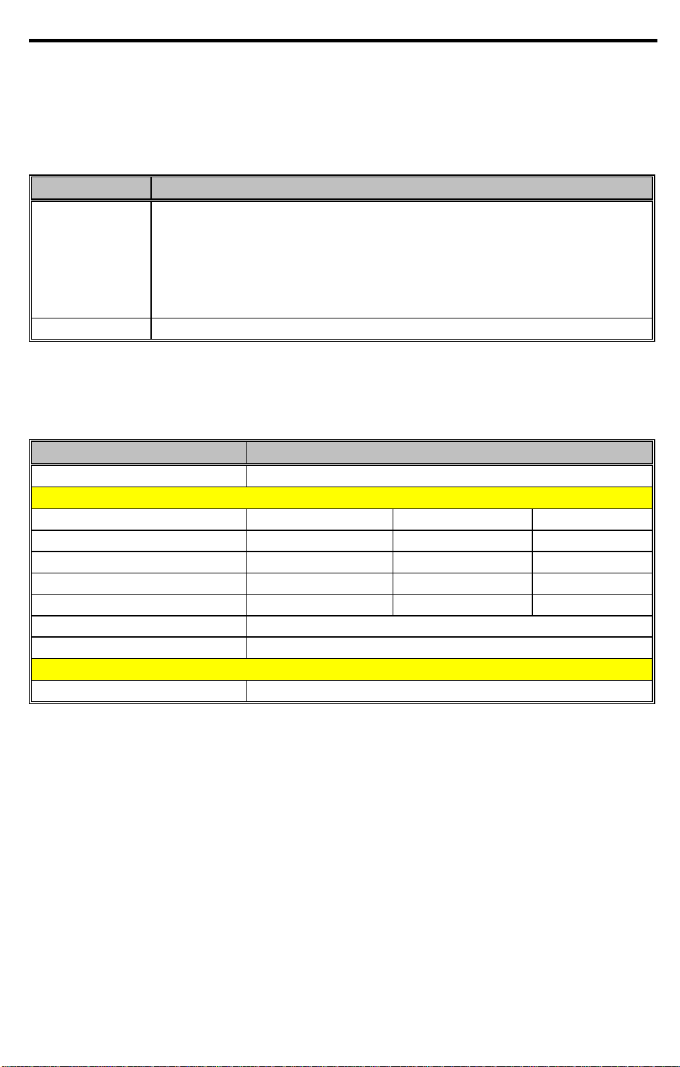
1.4.5 Processor
Table 1-7 Processor Specifications
Item Specification
CPU type P55C-133/150/166
CPU package TCP
Switchable processor speed (Y/N) Yes
Minimum working speed 0MHz
CPU core voltage 2.0V/2.45V/1.8V
CPU I/O voltage 2.5V/3.3V/2.5V
1.4.6 BIOS
Table 1-8 BIOS Specifications
Item Specification
BIOS vendor Acer
BIOS version V3.0
BIOS in flash EPROM (Y/N) Yes
BIOS ROM size 256KB
BIOS package type 32-pin PLCC
Same BIOS for STN color/TFT color (Y/N) Yes
The BIOS can be overwritten/upgradeable using the “AFLASH” utility
(AFLASH.EXE). Please refer to software specification section for details.
1.4.7 System Memory
Memory is upgradeable from 8 to 64 MB, employing 8-/16-/32-/64-MB2 64-bit soDIMMs (Small
Outline Dual Inline Memory Modules). After installing the memory modules, the system
automatically detects and reconfigures the total memory size during the POST routines. The
following lists important memory specifications.
• Memory bus width: 64-bit
• Expansion RAM module type:144-pin, 64-bit, small outline Dual Inline Memory Module
(soDIMM)
• Expansion RAM module size/configuration:
• 8MB (1M*16x4)
2
You can upgrade memory using 32-MB soDIMMs when these become available. Consult your dealer.
System Introduction 1-11

• 16MB (2M*8x8)
• 32MB (4M*16x4)
• 64MB (8M*8x8)
• Expansion RAM module speed/voltage/package: 60ns/3.3v/TSOP EDO
• EDO and fast-page mode DIMMs may be used together in a memory configuration.
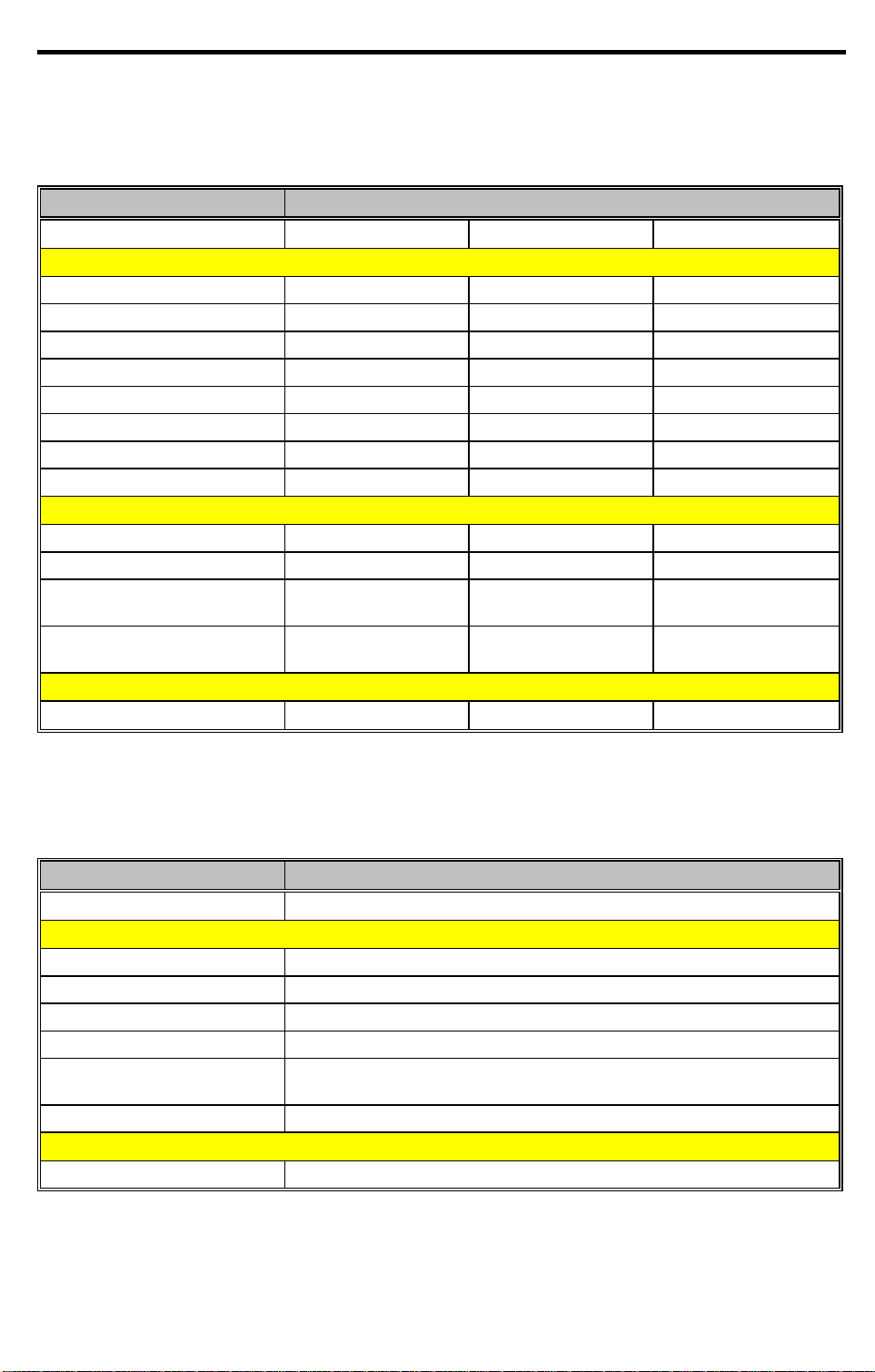
The following table lists all possible memory configurations.
Table 1-9 Memory Configurations
Slot 1 Slot 2 Total Memory
8 MB 0 MB 8 MB
0 MB 8 MB 8 MB
8 MB 8 MB 16 MB
16 MB 0 MB 16 MB
0 MB 16 MB 16 MB
16 MB 8 MB 24 MB
8 MB 16 MB 24 MB
16 MB 16 MB 32 MB
32 MB 0 MB 32 MB
0 MB 32 MB 32 MB
32 MB 8 MB 40 MB
8 MB 32 MB 40 MB
32 MB 16 MB 48 MB
16 MB 32 MB 48 MB
32 MB 32 MB 64 MB
64MB 0MB 64MB
0MB 64MB 64MB
64MB 8MB 72MB
8MB 64MB 72MB
64MB 16MB 80MB
16MB 64MB 80MB
64MB 32MB 96MB
32MB 64MB 96MB
64MB 64MB 128MB
1.4.8 Second-Level Cache
This notebook has 256KB second-level (L2) cache onboard.
1-12 Service Guide

1.4.9 Video Memory
Table 1-10 Video RAM Configuration
Item Specification
DRAM or VRAM DRAM(EDO type)
Fixed or upgradeable Fixed
Memory size/configuration 2MB (256K x 16 x 4pcs)
Memory speed 50ns
Memory voltage 3.3V
Memory package TSOP
1.4.10 Video
Table 1-11 Video Hardware Specification
Item Specification
Video chip C&T65555
Working voltage 3.3V
1.4.10.1 External CRT Resolution Support
Table 1-12 Supported External CRT Resolutions
Resolution x Color on
External CRT
640x480x16 60,75,85 60 Y Y
640x480x256 60,75,85 60 Y Y
640x480x65,536 60,75,85 60 Y Y
640x480x16,777,216 60,75,85 60 Y Y
800x600x16 56,60,75,85 60 Y Y
800x600x256 56,60,75,85 60 Y Y
800x600x65,536 56,60,75,85 60 Y Y
800x600x16,777,216 56,60,75,85 60 Y Y
1024x768x16 60,75,85,86I 60 Y Y
1024x768x256 60,75,85,86I 60 Y Y
1024x768x65536 60,75,85,86I 60 Y Y
1280x1024x16 60,75,86I 60 Y Y
1280x1024x256 60,75,86I 60 Y Y
CRT Refresh Rate Simultaneous on
TFT LCD
CRT only Simultaneous SVGA SVGA
Simultaneous on
STN LCD
System Introduction 1-13

1.4.10.2 LCD Resolution Support
Table 1-13 Supported LCD Resolutions
Resolution x Color on LCD Only TFT LCD (SVGA) DSTN LCD (SVGA)
640x480x16 Y Y
640x480x256 Y Y
640x480x65,536 Y Y
640x480x16,777,216 Y Y
800x600x16 Y Y
800x600x256 Y Y
800x600x65,536 Y Y
800x600x16777216 Y Y
1024x768x16 Y Y
1024x768x256 Y Y
1024x768x65536 Y Y
1280x1024x16 Y Y
1280x1024x256 Y Y
• Maximum resolution (External CRT): 1280x1024
Using software, you can set the LCD to a higher resolution than its physical
resolution, but the image shown on the LCD will pan.
1.4.11 Parallel Port
Table 1-14 Parallel Port Configurations
Item Specification
Number of parallel ports 1
ECP support Yes (set by BIOS setup)
Connector type 25-pin D-type
Location Rear side
Selectable parallel port (by BIOS Setup)
• Parallel 1 (3BCh, IRQ7)
• Parallel 2 (378h, IRQ7)
• Parallel 3 (278h, IRQ5)
• Disable
1-14 Service Guide

1.4.12 Serial Port
Table 1-15 Serial Port Configurations
Item Specification
Number of serial ports 1
16550 UART support Yes
Connector type 9-pin D-type
Location Rear side
Selectable serial port (by BIOS Setup)
• Serial 1 (3F8h, IRQ4)
• Serial 2 (2F8h, IRQ3)
• Disable
1.4.13 Audio
Table 1-16 Audio Specifications
Item Specification
Chipset YMF715
Audio onboard or optional Built-in
Mono or stereo Stereo
Resolution 16-bit
Compatibility SB-16 , Windows Sound System
Mixed sound sources Voice, Synthesizer, Line-in, Microphone, CD
Voice channel 8-/16-bit, mono/stereo
Sampling rate 44.1 kHz
Internal microphone No
Internal speaker / quantity Yes / 2 pcs.
Microphone jack Yes
Headphone jack Yes
1.4.14 PCMCIA
PCMCIA is an acronym for Personal Computer Memory Card International Association. The
PCMCIA committee set out to standardize a way to add credit-card size peripheral devices to a
wide range of personal computers with as little effort as possible.
There are two type II/I or one type III PC Card slots found on the left panel of the notebook. These
slots accept credit-card-sized cards that enhances the usability and expandability of the notebook.
ZV (Zoomed Video) port support allows your system to support hardware MPEG in the form of a
ZV PC card.
System Introduction 1-15

Table 1-17 PCMCIA Specifications
Item Specification
Chipset TI 1250A
Supported card type Type-II / Type-III
Number of slots Two Type-II or one Type-III
Access location Left side
ZV (Zoomed Video) port support Yes
1.4.15 Touchpad
Table 1-18 Touchpad Specifications
Item Specification
Vendor & model name
Power supply voltage (V) 5 ± 10%
Location Palm-rest center
Internal & external pointing device work simultaneously Yes
Support external pointing device hot plug Yes
X/Y position resolution (points/mm) 20
Interface PS/2 (compatible with Microsoft mouse driver)
Synaptics TM3202TPD-226
1.4.16 Keyboard
Table 1-19 Keyboard Specifications
Item Specification
Vendor & model name SMK KAS1901-0161R (English)
Total number of keypads 84/85 keys
Windows 95 keys Yes, (Logo key / Application key):
Internal & external keyboard work simultaneously Yes
1-16 Service Guide
1.4.16.1 Windows 95 Keys
The keyboard has two keys that perform Windows 95-specific functions. See Table 1-26.
Table 1-20 Windows 95 Key Descriptions
Key Description
Windows logo key Start button. Combinations with this key performs special functions, e.g.:
• Windows + Tab Activate next Taskbar button
• Windows + E Explore My Computer
• Windows + F Find Document
• Windows + M Minimize All
• Shift + Windows + M Undo Minimize All
• Windows + R Display Run dialog box
Application key Opens the application’s context menu (same as right-click).
1.4.17 FDD
Table 1-21 FDD Specifications
Item Specification
Vendor & model name Mitsumi D353F2
Floppy Disk Specifications
Media recognition 2DD (720K) 2HD (1.2M, 3-mode) 2HD (1.44M)
Sectors / track 9 15 18
Tracks 80 80 80
Data transfer rate (Kbits/s) 250 300 500 500
Rotational speed (RPM) 300 360 360 300
Read/write heads 2
Encoding method MFM
Power Requirement
Input Voltage (V) +5 ± 10%
System Introduction 1-17
1.4.18 HDD
Table 1-22 HDD Specifications
Item Specification
Vendor & Model Name Hitachi DK225A-21 IBM DTNA22160 IBM DDLA21620
Drive Format
Capacity (MB) 2160 2160 1620
Bytes per sector 512 512 512
Logical heads 16 16 16
Logical sectors 63 63 63
Logical cylinders 4889 4200 3152
Physical read/write heads 6 6 3
Disks 3 3 2
Spindle speed (RPM) 4464 4000 4000
Performance Specifications
Buffer size (KB) 128 96 96
Interface ATA-3(IDE) ATA-2 ATA-2
Data transfer rate
(disk-buffer, Mbytes/s)
Data transfer rate
(host-buffer, Mbytes/s)
DC Power Requirements
Voltage tolerance (V)
5.7 ~ 9.0 5 ~ 7.7 5 ~ 8.3
16.6 /33.3
(max., PIO mode 4)
5 ± 5%
16.6
(max., PIO mode 4)
5 + 5%
16.6
(max., PIO mode 4)
5 ± 5%
1.4.19 CD-ROM
Table 1-23 CD-ROM Specifications
Item Specification
Vendor & Model Name
Performance Specification
Speed (KB/sec) 2100 (14X ave. speed)
Access time (ms) 150 (Typ.)
Buffer memory (KB) 128
Interface Enhanced IDE (ATAPI) compatible
Applicable disc format CD-DA, CD-ROM, CD-ROM XA (except ADPCM), CD-I, Photo CD
Loading mechanism Soft eject (with emergency eject hole)
Power Requirement
Input Voltage (V) 5
1-18 Service Guide
Panasonic KMEUJDA110
(Multisession), Video CD, CD+
 Loading...